Chapter 1 1.1 1.2 1.2.1 1.2.2 1.3 1.4 1.5 1.6 1. 6.1 1.6.2 1.6.3 1.6.3.1 1.6.3.2 1.7 2 2.1 2.2 2.3 2.4 2.5 2.5.1 2.5.2 2.5.3 2.5.4 2.5.5 2.5.6 2.5.7 2.5.8 2.5.9 2.5.10 2.6 2.7 2.8 4246S HAWAIIAN ELECTRIC COMPANY, INC. GEOTHERMAL/INTER-ISLAND TRANSMISSION PROJECT REQUEST FOR PROPOSAL Title EXECUTIVE SUMMARY Letter from the Governor of Hawaii Letter from the President of Hawaiian Electric Company Letter from the President of Maui Electric Company PURPOSE AND GOALS SOLICITATION ROLES AND OBJECTIVES HECO STATE OF HAW AI I HAWAIIAN ELECTRIC COMPANY SYSTEM NATURE OF POWER REQUIREMENTS ORGANIZATION OF THE RFP EVALUATION CRITERIA PRELIMINARY EVALUATION COMPREHENSIVE EVALUATION CRITERIA Technical Proposal Commercial Proposal RFP DEFINITIONS PROPOSAL PREPARATION AND SUBMITTAL INQUIRY ACKNOWLEDGEMENT QUESTIONS AND CLARIFICATIONS SUBMITTAL DATE, LOCATION AND INTENT TO PROPOSE PROPOSERS CONFERENCES PROPOSAL PREPARATION PREPARATION EXHIBITS LANGUAGE/SYSTEM OF UNITS PRICING INFORMATION LIMITING CONDITIONS PROPOSAL COMPLIANCE REPRESENTATIVE SIGNATURES TECHNICAL PROPOSAL COMMERCIAL PROPOSAL MINIMUM INFORMATION REQUIREMENTS INFORMATION CONFIDENTIALITY PROPOSAL FEE 1

Welcome message from author
This document is posted to help you gain knowledge. Please leave a comment to let me know what you think about it! Share it to your friends and learn new things together.
Transcript
Chapter
1 1.1 1.2 1.2.1 1.2.2 1.3 1.4 1.5 1.6 1. 6.1 1.6.2 1.6.3 1.6.3.1 1.6.3.2 1.7
2 2.1 2.2 2.3
2.4 2.5 2.5.1 2.5.2 2.5.3 2.5.4 2.5.5 2.5.6 2.5.7 2.5.8 2.5.9 2.5.10 2.6 2.7 2.8
4246S
HAWAIIAN ELECTRIC COMPANY, INC. GEOTHERMAL/INTER-ISLAND TRANSMISSION PROJECT
REQUEST FOR PROPOSAL
Title
EXECUTIVE SUMMARY
Letter from the Governor of Hawaii Letter from the President of Hawaiian Electric Company Letter from the President of Maui Electric Company
PURPOSE AND GOALS SOLICITATION ROLES AND OBJECTIVES HECO STATE OF HAW AI I HAWAIIAN ELECTRIC COMPANY SYSTEM NATURE OF POWER REQUIREMENTS ORGANIZATION OF THE RFP EVALUATION CRITERIA PRELIMINARY EVALUATION COMPREHENSIVE EVALUATION CRITERIA Technical Proposal Commercial Proposal RFP DEFINITIONS
PROPOSAL PREPARATION AND SUBMITTAL INQUIRY ACKNOWLEDGEMENT QUESTIONS AND CLARIFICATIONS SUBMITTAL DATE, LOCATION AND
INTENT TO PROPOSE PROPOSERS CONFERENCES PROPOSAL PREPARATION PREPARATION EXHIBITS LANGUAGE/SYSTEM OF UNITS PRICING INFORMATION LIMITING CONDITIONS PROPOSAL COMPLIANCE REPRESENTATIVE SIGNATURES TECHNICAL PROPOSAL COMMERCIAL PROPOSAL MINIMUM INFORMATION REQUIREMENTS INFORMATION CONFIDENTIALITY PROPOSAL FEE
1
Chapter
3 3.1 3.1.1 3.1.2 3.1.3 3.1.4 3.1.5 3.1.6 3.2 3.2.1 3.3 3.3.1 3.3.2 3.3.3 3.3.4 3.4 3.4.1 3.4.2 3.4.3 3.4.4 3.4.5 3;4.6 3.4.7 3.5 3.5.1 3.5.2 3.5.3 3.5.4 3.5.5 3.5.6 3.6 3.6.1 3.6.2
3.6.2.1 3.6.2.2 3.6.2.3 3.6.2.4
4246S
HAWAIIAN ELECTRIC COMPANY, INC. GEOTHERMAL/INTER-ISLAND TRANSMISSION PROJECT
REQUEST FOR PROPOSAL
Title
TECHNICAL INFORMATION GENERAL TECHNICAL CONSIDERATIONS SEISMIC DESIGN ACTIVE LAVA FLOW CONSIDERATIONS MATERIALS CRITERIA MATURITY OF TECHNOLOGY DESIGN AND CONSTRUCTION STANDARDS LAND USE GEOTHERMAL RESOURCE TECHNICAL DATA AND INFORMATION REQUESTS GEOTHERMAL ENERGY GATHERING SYSTEM PIPING SYSTEMS SEPARATORS AND SCRUBBERS CONTROL SYSTEM TECHNICAL DATA AND INFORMATION REQUESTS ELECTRIC POWER PRODUCTION FACILITIES POWER CYCLE/HEAT BALANCE CIVIL/STRUCTURAL CONSIDERATIONS TURBINE-GENERATOR CONFIGURATION OTHER MECHANICAL SYSTEMS ELECTRICAL SYSTEM INSTRUMENTATION AND CONTROL SYSTEM TECHNICAL DATA AND INFORMATION REQUESTS AC TRANSMISSION SYSTEM RELIABILITY AND PROTECTION ELECTRICAL REQUIREMENTS STRUCTURAL REQUIREMENTS ATMOSPHERIC CONDITIONS OPERATION AND MAINTENANCE CONSIDERATIONS TECHNICAL DATA AND INFORMATION REQUESTS HVDC TRANSMISSION SYSTEM GENERAL TRANSMISSION PLAN CONVERTER AND CABLE TRANSITION LOCATIONS
AND TRANSMISSION LINE ROUTES Converter Terminals Overhead Transmission Line Routes Submarine Cable Routes Cable Transition Stations
11
Chapter
3.6.3
3.6.3.1 3.6.3.2 3.6.4 3.6.4.1 3.6.4.2 3.6.4.3 3.6.4.4 3.6.4.5 3.6.4.6 3.6.5 3.6.5.1 3.6.5.2 3.6.6 3.6.6.1 3.6.6.2 3.6.6.3 3.6.6.4 3.6.6.5 3.6.7 3.6.7.1 3.6.7.2 3.6.7.3 ;3.6.8 3.6.9 3.6.10 3.6.10.1 3.6.10.2 3.7 3.7.1 3.7.2 3.7.2.1 3.7.2.2 3.7.2.3
3.8
3.9
3.9.1 3.9.2 3.9.3 3.9.4
4246S
HAWAIIAN ELECTRIC COMPANY, INC. GEOTHERMAL/INTER-ISLAND TRANSMISSION PROJECT
REQUEST FOR PROPOSAL
Title
RATINGS AND CAPABILITIES OF CONVERTERS AND LINES
Operating Requirements Emergency Overload Requirements CONVERTER TERMINALS Operating Modes Equipment Data and Information AC and DC Harmonics and Harmonic Filters Reactive Compensation and Voltage Control Insulation Coordination HVDC System Studies and Testing OVERHEAD HVDC TRANSMISSION LINES Structural Design Guidelines Electrical Design Guidelines SUBMARINE CABLE Basic System Criteria Cable Design Parameters Design Constraints Switching, Splicing, Termination and Auxiliaries Manufacturing, Transport and Installation HVDC NEUTRAL GROUNDING SYSTEM Ground Electrodes Sea Electrode Metallic Return HVDC SYSTEM CONTROL AND PROTECTION HVDC COMMUNICATION AND TELECONTROL PROPOSAL REQUIREMENTS Base Proposal Options EXISTING AC SYSTEM CHARACTERISTICS METEOROLOGICAL AND ATMOSPHERIC CONDITIONS ELECTRICAL AND SYSTEM DATA System Operating Parameters System Study Data Existing Equipment Ratings and Operating
Stresses INTERCONNECTION REQUIREMENTS AT
RECEIVING SUBSTATION SYSTEM OPERATION, MONITORING COMMUNICATION
AND MAINTENANCE OVERALL SYSTEM INTEGRATION AND TELECONTROL COMMUNICATION AND TELECONTROL MONITORING AND REVENUE METERING MAINTENANCE PRACTICES AND ORGANIZATION
iii
Chapter
Tables 3.7A
Figures 3.5A 3.58 3.6A 3.68 3.6C 3.6D 3.7A 3.78 3.7C 3.7D 3.7E 3.7F 3.7G 3.7H 3.7I 3.7J 3.7K 3.7L 3.8A
4 4.1 4.2 4.3 4.4 4.4.1 4.5 4.6
5 5.1 5.2 5.2.1 5.2.2 5.2.3 5.3
Tables 5.2A 5.28 5.2C
42465
HAWAIIAN ELECTRIC COMPANY, INC. GEOTHERMAL/INTER-ISLAND TRANSMISSION PROJECT
REQUEST FOR PROPOSAL
Title
Physical Conditions
Geothermal Power Transmission System Possible HVDC Transmission Routes Possible Hawaii HVDC Routes Possible Maui HVDC Routes Possible Oahu HVDC Routes Potential Hawaii to Maui Cable Routes HECO Positive Sequence Impedance Diagram HECO Zero Sequence Impedance Diagram HECO 1994 Peak Load Flow HECO 1994 Minimum load Flow HECO 1994 Average Load Flow HECO 138 kV System HEGO Generator Data HECO Turbine Data HECO Customer Data Hawaii Insulation Areas Maui Insulation Areas Oahu Insulation Areas Preliminary Aniani Single- Line Diagram
RELIABILITY SYSTEM CHARACTERISTICS HECO RELIABILITY ASSUMPTIONS AND CONSIDERATIONS RELIABILITY ASSESSMENT GEOTHERMAL WELLFIELD RELIABILITY PROJECT SYSTEM RELIABILITY REQUIREMENTS REFERENCES FOR CHAPTER 4
POWER DELIVERY AND SCHEDULE CAPACITY ENERGY PEAK LOAD MINIMUM LOAD DAILY AND YEARLY VARIATIONS PROPOSED SCHEDULE
Yearly Morning Peak Demand Yearly Evening Peak Demand Yearly Minimum Demand
iv
Chapter
Figures 5.1A 5.2A 5.2B
6.0 6.1 6.2
7 7.1 7 .1.1 7 .1.2 7 .1.3 7 .1.4 7 .1.5 7 .1.6 7 .1. 7 7.2 7.2.1 7.2.2
7.2.3
7.2.3.1 7.2.3.2 7.2.3.3 7.2.3.4 7.2.3.5 7.2.3.6 7.2.3.7
7.2.4 7.2.4.1 7.2.4.2 7.2.4.3 7.2.4.4 7.2.4.5
7.2.4.6
7.2.4.7 7.2.4.8
4246S
HAWAIIAN ELECTRIC COMPANY, INC. GEOTHERMAL/INTER-ISLAND TRANSMISSION PROJECT
REQUEST FOR PROPOSAL
Title
Capacity Considerations Energy Considerations HECO Daily Load Variations
PERMIT AND ENVIRONMENTAL INFORMATION PERMITS ENVIRONMENTAL INFORMATION
COMMERCIAL INFORMATION FINANCIAL PROJECTIONS AVOIDED COSTS PROJECT SCENARIOS GEOTHERMAL RESOURCE COSTS CAPITAL COSTS OPERATION ND MAINTENANCE COSTS PROPOSED PRICE FOR POWER OPERATIONAL CONSTRAINTS AND EFFECTS ON REVENUE CONTRACTUAL PROVISIONS POWER PURCHASE AGREEMENT GENERAL DESCRIPTION OF TERMS AND CONDITIONS TO
POWER PURCHASE AGREEMENT DESCRIPTION OF THE REQUIRED GUARANTEE
STRUCTURE FOR THE PROJECT Milestone Schedule Right of HECO to Defer or Cancel Security Interests Equipment Guarantees Guarantor Commitments Loss or Reduction of Service Right to Purchase Project (or any Components
thereof) or to Extend Term of the PPA INSURANCE REQUIREMENTS Worker's Compensation and Employer's Liability General Liability Insurance Automobile Liability Insurance Builders All-Risk Insurance All-Risk Property/Comprehensive Boiler and
Machinery Insurance (Upon Completion of Construction)
Business Interruption Insurance (Upon Completion of Construction)
Geothermal Reservoir Insurance Project Liability Errors and Omissions
Insurance or Agreed Upon Alternatives
v
Chapter
7.2.5 7.2.6
7.2.6.1 7.2.6.2 7.3 7.3.1 7.3.2 7.3.2.1 7.3.2.2 7.3.3 7.3.4 7.3.5 7.3.6 7.4 7 .4.1
7.4.2
7.4.3
7.5
Attachments 7.1A 7.1B 7.1C
8 8.1 8.1.3 8.1.4 8.3 8.3.6 8.3.6.2 8.3.6.4 8.3.6.7 8.3.7 8.3.7.2 8.3.8 8.4 8.5 8.7.1 8.7.1.1 8.7.1.6 8.8
4246S
HAWAIIAN ELECTRIC COMPANY, INC. GEOTHERMAL/INTER-ISLAND TRANSMISSION PROJECT
REQUEST FOR PROPOSAh
Title
REQUIREMENTS FOR INDEMNIFICATION DESCRIPTION OF EVENTS OF DEFAULT AND REMEDIES
AVAILABLE DUE TO DEFAULT Events of Default Remedies Available Upon Default INFORMATION ON PROPOSER PROPOSERS LEGAL IDENTITY AND COMPOSITION FINANCIAL REQUIREMENTS Existing Entity New Entity FINANCING PLAN MANAGEMENT STRUCTURE PRIOR EXPERIENCE REGULATORY ISSUES EVALUATION CRITERIA FINANCIAL CONDITION, CAPABILITY TO FINANCE
AND FINANCING PLAN ORGANIZATION CREDENTIALS, AVAILABILITY AND
QUALITY OF PROJECT PERSONNEL RESOURCES AS EVIDENCED IN THE MANAGEMENT PLAN
PERFORMANCE GUARANTEES, INSURANCE AND INDEMNIFICATION REQUIREMENTS
REFERENCES FOR CHAPTER 7
HECO November 25, 1988 Electric Utility System Cost Data ORMAT Energy Systems, Inc. Letter of March 31, 1989 Mid-Pacific Geothermal, Inc. letter of April 3, 1989
TECHNICAL FEASIBILITY OF A MAUl TAP PURPOSE AND GOALS MAUI ELECTRIC COMPANY SYSTEM NATURE OF POWER REQUIREMENTS TECHNICAL INFORMATION HVDC TRANSMISSION SYSTEM Converter Locations Converter Terminals HVDC Neutral Grounding System EXISTING AC SYSTEM CHARACTERISTICS Electric and System Data MECO MAALAEA SUBSTATION RELIABILITY POWER DELIVERY AND SCHEDULE FINANCIAL PROJECTIONS Avoided Costs Potential Price for Power REFERENCES FOR CHAPTER 8
vi
Chapter
Attachment 8.7A
Figures 8.3A 8.3B 8.3C 8.3D 8.3E 8.3F 8.3G 8.3H 8.3I 8.3J
4246S
HAWAIIAN ELECTRIC COMPANY, INC. GEOTHERMAL/INTER-ISLAND TRANSMISSION PROJECT
REQUEST FOR PROPOSAL
Title
MECO August 1, 1988 Electric Utility System Cost Data
Geothermal Power Transmission System (Including Maui Tap) MECO 69 kV Impedance Diagram MECO 1993 Peak Load Flow MECO 1993 Minimum Load Flow MECO 1993 Average Load Flow MECO 69 kV System MECO Generator Data MECO Turbine Data MECO Customer Data Preliminary Maalaea Single Line Diagram
Vll
•
Chapter
Appendix A
A.1
A.2
A.3
A.4
A.5
A.6 A.7
A.S
A.9
A.10 A.11 A.12
Tables A-1 A-2 A-3
A-4
Figures A-1 A-2 A-3 A-4 A-5
A-6 A-7 A-8
A-9
4246S
HAWAIIAN ELECTRIC COMPANY, INC. GEOTHERMAL/INTER-ISLAND TRANSMISSION PROJECT
REQUEST FOR PROPOSAL
Title
GEOTHERMAL RESOURCES OF THE KILAUEA EAST RIFT ZONE
HAWAIIAN ISLANDS- ORIGIN AND ACTIVITY
KILAUEA EAST RIFT ZONE AND ITS GEOTHERMAL RESOURCE POTENTIAL
LEGAL STATUS AND REGULATION OF GEOTHERMAL RESOURCES
AVAILABILITY AND ACCESSIBILITY; PROSPECTIVE AREAS
ELECTRIC GENERATION AND RESOURCE PRODUCTION IN THE KERZ
GEOTHERMAL RESERVOIR POTENTIAL IN THE KERZ GASEOUS AND LIQUID WASTE DISPOSAL FROM
GEOTHERMAL WELLFIELD ACTIVITIES VOLCANIC AND SEISMIC IMPACTS ON WELLFIELD
DEVELOPMENT GEOTHERMAL WELLS AND WELLFIELD CONCEPTS AND
OPTIONS MATURITY OF TECHNOLOGY OPERATIONS AND MAINTENANCE REFERENCES FOR APPENDIX A
Island of Hawaii Volcanic Centers KERZ Deep Geothermal Wells Geothermal Fluid Chemical Composition
Composite Data Noncondensable Gas Composition Composite
Data
Volcanic Centers and Rift Zones Kilauea Volcano and Rift Zones Kilauea East Rift Zone Cross-Section HGP-A Well Temperatures Hypothetical East Rift Zone Geothermal
Reservoir Geothermal Resource Subzones HGP-A Operational Summary Displacements Associated with November 1975
Earthquake Lava Flow Hazard Zones
viii
Chapter
Appendix B
B.1 B.1.1 B.1.1.1 B.1.1.2 B.1.1.3 B.1.1.4 B.l.l.S B.1.1.6 B.1.2
B.1.2.1 B.1.2.2 B.1.2.3 B.1.3
B.1.3.1 B.1.3.2 B.1.3.3 B.2 B.2.1 B.2.1.1 B.2.1.2 B.2.1.3 B.2.1.4 B.2.1.5 B.2.1.6 B.2.1.7 B.2.1.8 B.2.1.9 B.2.2 B.2.2.1 B.2.2.2 B.2.2.3 B.2.2.4 B.3
Appendix C
4246S
HAWAIIAN ELECTRIC COMPANY, INC. GEOTHERMAL/INTER-ISLAND TRANSMISSION PROJECT
REQUEST FOR PROPOSAL
Title
PERMIT/ENVIRONMENTAL INFORMATION FOR THE GEOTHERMAL/INTER-ISLAND TRANSMISSION PROJECT
PERMITS GENERAL INFORMATION DEVELOPER Responsibility/State Assistance Comprehensive Permit System Public Hearings International Waters Environmental Impact Statement Geothermal Resource Subzones PERMITS FOR GEOTHERMAL RESOURCES, ENERGY
GATHERING SYSTEMS, POWER PRODUCTION FACILITIES AND CONVERTER TERMINALS
Federal State County PERMITS FOR INTER-ISLAND ELECTRIC TRANSMISSION
SYSTEM Federal State County ENVIRONMENTAL INFORMATION TERRESTRIAL ENVIRONMENT Soils, Geology, Seismic, Volcanic Meteorology and Air Quality Hydrology/Water Quality Noise Fauna/Flora Archaeological/Cultural Land Use and Zoning Aesthetics/Visual Impact Social/Economic MARINE Bathymetry Marine Biology Physical Oceanography Navigation/Ocean Uses BIBLIOGRAPHY FOR APPENDIX B
REQUEST FOR PROPOSALS: DEVELOPMENT OF A MASTER PLAN, TRANSMISSION LINE ROUTING STUDY, AND ENVIRONMENTAL IMPACT STATEMENT FOR HAWAII'S PROPOSED GEOTHERMAL/INTER-ISLAND CABLE PROJECT
ix
.JOHN WAIHEE GOVERNOR
EXECUTIVE CHAMBERS
HONOLULU
April 28, 1989
IJ!r. Harwood D. Williamson, President Hawaiian Electric Company, Inc. 900 Richards Street Honolulu, Hawaii 96813
Dear Mr. Williamson:
I am pleased to affirm the strong and continuing support of the State of Hawaii for the Hawaii Geothermal/ Interisland Transmission Project, and endorse the joint efforts of the State and Hawaiian Electric Company (HECO) in seeking proposals for the development of our State's geothermal resources. With cooperative assistance from the State and HECO, I am confident that the creative forces of the private sector will provide viable proposals to insure Hawaii and its people a long-term source of electrical power that is generated from our own renewable energy resource base.
I believe that we mutually and realistically recognize the enormous scope of the venture. While the benefits are great, so too are the risks. To the extent necessary and possible, the State of Hawaii will act to facilitate the efforts of the private sector in determining the financial and technical feasibility of this project and in constructing viable proposals.
I have directed those of my Cabinet most directly involved in the development of geothermal resources to lend the assistance that will be needed for private sector interests to meaningfully evaluate the viability of developing geothermal resources in Hawaii. To that end, the State will establish and staff a public documents room; this will be a source of technical and economic information specifically pertinent to this project. In addition, a facility will be available to serve as a permit information and coordination center, a repository of relevant laws, rules, and permitting requirements. In general, these facilities will centrally locate and make easily accessible the documents which we believe will be useful to those preparing responses to the request for proposal to be issued by HECO.
Mr. Harwood D. Williamson April 28, 1989 Page Two
The State can, and will, be helpful in other ways as well. I have recently commissioned the preparation of a master development plan. The objective of this effort is to determine citizen concerns and, with input from the community, format the best means by which to develop several hundred megawatts of geothermal power on Hawaii. Public involvement is crucial to this study, and my goal is to seek the cooperation and support of Hawaii's citizens for this renewable energy project. I will actively work for a coordinated effort with Federal agencies and county governments toward this objective.
Based on the results of this development plan, the State will move to obtain what permits it can for the commercial project, including the preparation of appropriate environmental impact statements, and will work closely with the selected developer to facilitate the acquisition of all other required permits. Recognizing ~he critical nature of issues associated with this venture, my Administration will work cooperatively with all parties involved to help insure its timely progress. If deemed appropriate, I will personally involve myself in addressing issues that may be impeding the advancement of this project.
Finally, I recognize that the State must be receptive to ideas for public financial assistance if such assistance is necessary. The magnitude of the venture · precludes significant direct funding by the State; however, there-may be mechanisms for indirect financial support. My Administration is willing to explore such mechanisms with those prospective developers whose proposals are judged technically viable, but only if we are satisfied the project cannot be accomplished without State support.
We are indeed fortunate to have a natural resource which offers the potential of energy security for Hawaii's people and its economy. I strongly believe the development of geothermal energy is a key to achieving the State's goal of significant reduction in imported oil. To this end, I again pledge my personal support and the support of my Administration.
With kindest regards,·
JOHN WAIHEE
Harwood D. Williamson President and Chief Operating Officer
Hawaiian Electric Company, Inc.· PO Box 2750 ·Honolulu, HI 96840-0001
May 1, 1989
TO: Potential Proposers
SUBJECT: Request for Proposal for Geothermal/Interisland Transmission Project
Hawaiian Electric Company and the State of Hawaii have worked together on a cooperative basis since 1982 to bring about the development of deep water cable transmission technology in the hope that one day the geothermal potential of the Big Island might be utilized to meet a significant portion of the electrical energy needs of the island of Oahu. Research on the deep water cable system is nearly complete and it is time to take the next step and pursue commercial development of the geothermal resource and the cable system.
Although this request for proposal is a Hawaiian Electric Company effort, HECO clearly recognizes that it would most likely not produce any results if it were not for the concurrent support of the State of Hawaii to expedite the acquisition of transmission corridors, streamline the permitting process, prove the extent of the geothermal resource, and complete the final phase of the deep water cable research program.
HECO supports the State's goal of reducing Hawaii's dependence on imported oil and believes that this cooperative effort has the highest potential for making a significant impact on efforts to achieve that goal. We are grateful for the cooperative assistance from the State and look forward to your response .
..
An HEI Company
Maui Electric Company, Ltd. • 210 West Kamehall}eha Avenue • PO Box 398 • Kahului, MaUl, HI 96732-0398 • (808) 871-8461
Arden G. Henderson President
Mr. H. D. Williamson President Hawaiian Electric Company, Inc. P. o. Box 2750 Honolulu, HI 96840-0001
Dear Dan,
April 28, 1989
As President of Maui Electric Company (MECO), I am writing to express keen interest in the possibility of obtaining power from the 500 megawatt Hawaii geothermal/interisland cable project which HECO is now soliciting.
I ask that an additional requirement be included in HECO's request for proposals for an assessment by the proposers as to whether an electrical tap on Maui is technically feasible. We believe the inclusion of our request may provide a benefit to all parties directly interested in HECO's RFP. However, we are· cognizant that without HECO's Power Purchase Agreement ("PPA"), it is unlikely that MECO's purchase of up to 50 megawatts of electricity could alone justify the cost to develop and transmit the Big Island's geothermal energy. Hence, any definitive discussions regarding MECO's purchase of electricity will not be entertained unless and until a PPA has been executed by the successful proposer and HECO. For purposes of determining the technical feasibility of a possible tap, proposers should be required to evaluate and discuss, among other things, whether or not such a tap might cause uncontrollable disturbances to either MECO's or HECO's system if one or the other system were to experience a disruption.
Assuming that the analysis determines technical feasibility, and after HECO successfully negotiates a PPA with the owners or operators of the geothermal project, MECO will be very interested in discussing with the geothermal developers the possibility of purchasing up to 50 megawatts of electricity to be delivered after 1995. We will be pleased to have qualified developers discuss with and propose to HECO, on MECO's behalf, the technical feasibility of providing a tap on Maui.
Please include this letter in the RFP so that interested parties will be aware of MECO's interests.
Sincerely,
An HEI Company
EXECUTIVE SUMMARY
Hawaiian Electric Company, the _electric utility that serves the island of
Oahu and the ci t.y of Honolulu, is interested in purchasing up to 500
megawatts of electricity generated from geothermal resources on the island
of Hawaii and transmitted by a combination of overland transmission and
submarine cable to Oahu. Hawaiian Electric Company wishes to decrease its
dependence on imported oil and strengthen the state's economy. The
presence of recoverable geothermal energy on the island of Hawaii has been
known for some time. The conversion of geothermal energy to electricity is
now a proven, accepted technology. The federal and state research efforts
on the Hawaii Deep Water Cable project have resulted in confidence that a
submarine cable can be designed, fabricated and installed to transmit
electricity from the island of Hawaii to Oahu. Hawaiian Electric Company
has a need for power by 1995. The availability of the geothermal
conversion and cable technologies and Hawaiian Electric's power
requirements have led to this solicitation for power purchase.
This Project is strongly supported by Hawaiian Electric Company and the
state government. Hawaiian Electric Company's support for the Project is
evidenced by the letter from its President. The Governor of the State of
Hawaii has also expressed his interest and support. Letters from these
individuals are attached following this Summary.
THE PROJECT
The Project consists of designing, constructing, installing, financing,
owning, operating and maintaining an enterprise that will generate
electricity from geothermal resources on the island of Hawaii and deliver
at the point of interconnection on Oahu up to 500 megawatts (MW) of
electricity. Hawaiian Electric Company (HECO) will purchase power on Oahu;
it does not seek an ownership or operating interest in the Project.
Organizations that have the technical, managerial and financial expertise
to develop this Project, or cause it to be developed through others, should
respond to this Request for Proposal (RFP).
i 4396S
•
The intent of the RFP is to solicit conunercial interest in this Project.
Since HECO will not own the Project, the RFP is a performance related
specification. The RFP does request technical information on the proposed
design. HECO is not suggesting a price for the Project's power. Proposing
organizations should estimate the cost of their Project design and provide
a pricing proposal.
Qualified organizations are encouraged to submit Proposals even in that
circumstance where it is believed that the acceptability of the offered
price for energy is contingent upon actions or assistance by third parties,
such as the State of Hawaii.
Hawaiian Electric's present peak load of approximately 1100 MW is
anticipated to grow at a moderate growth rate of 2.2 percent/year to about
1600 megawatts in 2005. The HECO system can use 125 MW of baseload power by
1995, more if the power supply is capable of being cycled to more closely
match daily load variations, and up to 500 MW in later years. From HECO's ~
perspective, power needs are dependent upon forecasted load growth, unit
retirements, installed capacity and, ultimately, HECO' s assessment of the
reliability of the power generated by the Project and the degree and timing
of availability of that power.
THE REQUEST FOR PROPOSAL
The next increment of generation required by the Hawaiian Electric system
is about 140 MW in 1995. HECO has to make a decision on this increment by
December 1990 to ensure that generation will be available in 1995. Chapter
5 of the RFP discusses the schedule and the need for power in detail.
The power produced by the Project could potentially represent a large
portion of the electric power supply for Oahu. To protect the interests of
its customers, HECO is very concerned that the Project represent a reliable
supply of electric power. The RFP does not specify reliability indices for
11
4396S
the Project. However, so that HECO can place confidence in the Project,
Chapter 4 requires detailed reliability and availability data which can be
independently confirmed and evaluated by HECO.
Careful attention must be paid to design and construction to ensure the
reliable operation of the Project. Since the successful PROPOSER will be
responsible for the performance of the Project, HECO is not providing
design specifications. Chapter 3 of the RFP does identify those technical
design considerations and conditions which HECO believes will contribute
significantly to a viable Project. It is recognized that only a conceptual
design for the Project will exist at the Proposal stage.
Maui Electric Company, Ltd. is interested in determining the technical
feasibility of a possible SO MW tap. Chapter 8 presents data on the Maui
system to assist in this determination.
The Project would not be possible without the geothermal resource. While
it is believed that the geothermal resources on the island of Hawaii are
extensive, not until development is underway and exploration programs are
completed is there likely to be a high degree of certainty about the
capability of the resource to support the full 500 MW desired from the
Project. As a result, it is expected that PROPOSERS will have questions
about both the nature and extent of the resource and, as importantly,
access to the resource. Included as Appendix A to this RFP is a report,
commissioned by HECO, that describes in summary fashion much of the
available information about the resource. The PROPOSER is invited to
consider that report as well as other information that will be made
available by the State of Hawaii in a public document room established for
the purpose of facilitating ease of access for potential PROPOSERS to
publicly-held information.
This project will be a major undertaking in the state of Hawaii. It is
assumed that a variety of impacts will occur, many of which will require
the approval of various local, state and federal agencies. Thus, a summary
of environmental information is presented in Appendix B to assist in
iii 4396S
preparing the Proposal. Appendix B also includes a summary of the permits
and regulations that likely will affect the Project. The timely
acquisition of permits and approvals will be a central consideration in
HECO's evaluation of the Proposals.
To facilitate the permitting process, the State of Hawaii has already
conducted a very significant number of studies addressing the impacts of
geothermal development on the island of Hawaii. As noted in the letter of
the Governor of Hawaii, the State has also recently undertaken the drafting
of a master plan and a programmatic Environmental Impact Statement for the
development of 500 MW of geothermal power on the island of Hawaii.
A Project of this magnitude requires a very carefully written contract for
the protection of all parties, including the power customers on Oahu.
While a sample power purchase agreement is not presented in the RFP, the
major items of concern to HECO are discussed in Chapter 7. Chapter 7 also
requests specific information on the economic feasibility of the Project
and on the financing plan_proposed.
The Project is only as viable as the strength and integrity of the
developing organization. Some very specific details of the proposing ~
organization are requested in Chapter 7. Among other things, the
successful PROPOSER must be a U.S. entity, although it can have foreign
ownership, and the
financial backing.
PROPOSER, or its owners, must also have very solid
HECO also requires a detailed understanding of the
organizational structure of the entity or entities proposing to undertake
this Project and requires the presentation of the management structure and
personnel who will be responsible for the execution of this Project and its
long-term operation.
THE PROPOSAL AND EVALUATION PROCESS
The schedule for evaluation and selection of a Proposal is set forth in the
RFP. There is a conference open to all PROPOSERS on June 5, 1989. All
those who intend to submit a Proposal are requested to so notify HECO by
iv 4396S
June 15, 1989. Identification of team members and a firm statement of an
intent to propose are required by August 1, 1989. There will be separate,
private meetings with the PROPOSERS beginning on September 5, 1989.
Technical Proposals are .due on November 1, 1989, and Commercial Proposals
on December 1, 1989. HECO will qualitatively evaluate the Proposals and
establish a short list.
HECO will then conduct a more detailed evaluation of the short listed
Proposals. These evaluations will lead to negotiations with one or more
PROPOSERS. It is planned to have one or more power purchase agreements
negotiated for signature by October 1, 1990, with the intent of reaching a
decision by December 31, 1990.
It is recognized that PROPOSERS will likely not have reached agreement on
rights to sufficient geothermal resources by the time Proposals are
submitted. PROPOSERS selected for the short list, however, will be
expected to begin or continue negotiations for the resource so that
agreements are in place by October 1, 1990. In this regard, the major
existing geothermal leaseholders have expressed their willingness to
cooperate with PROPOSERS on this Project. Hawaiian Electric will not sign
a power purchase agreement that does not contain rights to sufficient
geothermal resources for full development of the Project.
Hawaiian Electric Company urges those organizations which have the
requisite technical, managerial, and financial expertise to propose on this
Project. The Project promises to be one of the more interesting and
demanding electric power projects of this century, with significant
exposure around the world for the organization which develops this Project.
v 4396S
CHAPTER 1: PURPOSE AND GOALS
1.1 SOLICITATION
The Hawaiian Electric Company, Inc. (HECO) is requesting Proposals
from qualified organizations to deliver for sale to HECO up to 500
megawatts (MW) of electricity generated from geothermal resources
on the island of Hawaii and transmitted to HECO's system on Oahu.
These organizations should submit Proposals to finance, design,
construct, install, own, operate and maintain the geothermal
resource development,
transmission project
Request for Proposal
electric power generation and inter island
in the state of Hawaii solicited by this
( RFP) .
The successful PROPOSER to this solici ta"tion (the DEVELOPER) wi 11
develop or cause to be developed the geothermal resources on the
island of Hawaii, convert or have converted those resources to
electricity and transmit or have transmitted to Oahu by means of
an overland and submarine interisland cable transmission system up
to 500 MW of ~lectr ici ty for purchase by HECO. This integrated
geothermal resource development, electric power generation and
interisland transmission system is hereinafter referred to as the
Project. It is desired that delivery of geothermally generated
electricity from the Project commence early in calendar year 1995.
All qualified organizations are strongly encouraged to submit a
Proposal. A qualified organization is one that, alone or in
conjunction with other participants, has the technical, managerial
and financial expertise to develop the project and who has, or
parent or other guarantor has, the financial strength necessary to
assure HECO of the successful completion and continuing operation
of the Project.
1-1
00844C-1869600-Dl
The desired schedule for the RFP is as follows:
Issue request for Proposals Open PROPOSERS conference Return Inquiry Acknowledgment form (Exhibit 2.1A) PROPOSERS return Intent to Propose form
(Exhibit 2.3A) and identify team makeup and structure
Meetings with intended PROPOSERS Technical Proposals due Commercial Proposals due Complete preliminary evaluation and prepare
short list Complete evaluation and negotiation of draft
contract with selected PROPOSER(s) Decision target date
5/1/89 6/5/89
6/15/89
8/1/89 9/5/89
11/1/89 12/1/89
2/1/90
10/1/90 12/31/90
The meeting with intended PROPOSERS in September 1989 will be
mandatory for those who intend to respond.
be in Honolulu, Hawaii.
All 1989 meetings will
HECO intends to develop a short list of PROPOSERS upon completion
of the preliminary evaluation of responses to this RFP. Selection
for this list will be based on HECO's evaluation of the responses
and such factors as it believes appropriate to best meet HECO's
needs.- To make a final determination, HECO intends to conduct
detailed discussions with each of the PROPOSERS on the short list.
It is anticipated that negotiations of the provisions of a power
purchase agreement ( PPA) will be undertaken with selected
PROPOSER(s} on the short list and a final decision made in
December, 1990.
HECO intends to execute a PPA with the successful PROPOSER
(DEVELOPER}. This PPA will obligate the DEVELOPER to sell and
HECO to buy AC electrical energy at a designated point of
interconnection on the island of Oahu. HECO does not intend to
own any portion of the Project and this solicitation should not be
interpreted as a solicitation by HECO for any ownership interest
in the Project.
1-2
00844C-1869600-Dl
"~'"'
,.
lin
HECO will not pay for any of the costs incurred by PROPOSERS
relating to this solicitation.
The information contained in this RFP is drawn from a variety of
sources and represents the best efforts of HECO to present
information useful to potential PROPOSERS in preparing Proposals
in response to the RFP. However, HECO makes no warranty with
respect to the information contained herein, and the information
contained herein should not be be construed as representations of
HECO with respect to the legal, economic or business circumstances
of HECO, actions of the State of Hawaii, or other conditions or
circumstances affecting the geothermal development, electricity
rates or service or similar matters.
1.2 ROLES AND OBJECTIVES
1. 2.1 HECO
The objective of this RFP is to execute a satisfactory PPA between
HECO and the successful PROPOSER to supply on a long-term basis at
an agreed upon cost per kilowatt hour up to 500 MW (net) (or any
agreed upon increment thereof) of geothermally-generated
electrical energy. This electricity would be transmitted from the
island of Hawaii to a point of interconnection with HECO's system
on Oahu via an overland and undersea transmission system. This is
shown in diagrammatic form on Figure 3.5B. A subsidiary goal is
evaluating the technical feasibility of a tap on Maui.
1.2.2 STATE OF HAWAII
Increased energy self-sufficiency is a specific State objective
expressed in the Hawaii State Plan (Chapter 226, HRS). In order
to achieve this objective one of the policies stated in the Hawaii
State Plan is to, " ... promote the use of renewable energy sources"
(Section 226-18 HRS). Further, one of the priority guidelines in
1-3
00844C-1869600-Dl
the Hawaii State Plan is " ... commercialization of renewable energy
resources" (HRS 226-1013[f]).
In Hawaii, the term renewable energy resources is almost
synonymous with indigenous energy resources. Geothermal may be
the only indigenous resource available in
Hawaii, whose conversion to base-load
commercially viable in the near future.
large quantities
electricity may
in
be
The State of Hawaii
indigenous resources
is increasingly interested
to help meet its energy
in renewable,
needs. The
Government of Hawaii, both the Administration and the Legislature,
have expressed support for policies designed to shift electricity
generation toward geothermal energy as a source to supplement
existing oil-based electric power generation.
In support of the State's goal to have indigenous energy resources
developed in order to achieve greater independence from imported
petroleum, the State of Hawaii has stated that it will assist the
DEVELOPER in obtaining the necessary permits and preparing the
necessary environmental impact assessments and/or statements for
the Project. Please see Governor Waihee' s letter to H. D.
Williamson (attached following the· Executive Summary).
The State has already completed extensive environmental reviews
for the cable system (August, 1987) and for the geothermal
development (March, 1989). The State has continued this process
by issuing on March 10, 1989, a Request for Proposal for the
..
"Development of a Master Plan, Transmission Line Routing Study, ~.
and Environmental Impact Statement for Hawaii's Proposed
Geothermal/Inter-Island Cable Project," included here as Appendix
C. The master plan and transmission study should be completed in
early 1990. It is anticipated that an EIS will be initiated and
completed as soon as practicable after enough elements of the
master plan and transmission routing report are available. The
1-4
00844C-1869600-Dl ...
EIS will be prepared around a logical but theoretical development
scenario. When applications for permits are made, it is
anticipated that one or more EIS supplements analyzing actual
development scenarios will likely have to be performed by, and at
the expense of, the Project DEVELOPER.
1.3 HAWAIIAN ELECTRIC COMPANY SYSTEM
HECO is a regulated public utility company that is a wholly owned
subsidiary of Hawaiian Electric Industries, Inc. (HEI), a publicly
held corporation. Located on the island of Oahu, HECO is
responsible for providing electrical service to a population of
approximately 830,000 residents, a visitor industry that hosts
approximately six million people a year, and several military
installations.
The HECO system is presently comprised of 16 oi~-fired generating
units located at three sites Honolulu, Waiau and Kahe.
Non-firm energy is also purchased by HECO from various small,
independent power producers. Firm capacity, currently provided
entirely by HECO, totals 1,277 MW, which is expected to increase
to 1,608 MW by the end of 1992 when two cogeneration facilities
are expected to be in service. At that time the generation mix of
the HECO system is expected to be 1,174 MW (73.0 percent) base
load, 332 MW (20.7 percent) cycling and 102 MW (6.3 percent)
peaking.
HECO recorded a peak demand of 1, 068 MW in December, 1988 and
produced a total of 6,793,308,000 kilowatt-hours in 1988.
Purchased power for the same period was 102,949,600 kilowatt
hours. System load factors range from 73 percent to 80 percent on
a weekly basis.
1-5
00844C-1869600-Dl
The type of firm capacity that HECO believes is most desirable for
its projected capacity requirements after 1992 has the following
characteristics:
• Dispatchability
The generation should be capable of following typical demand
fluctuations on a daily basis.
• Cycling Capability
To complement the committed projected generation mix of base
load, cycling and peaking units, the ideal generation unit
should be capable of cycling off-line on a daily basis.
• Spinning Reserve
As an isolated utility, HECO places an emphasis on three
second quick load pick-up, i.e., the amount of load that a
unit can pick up and sustain within three seconds of a major
system frequency excursion.
• Reliability and Availability
HECO generating units exhibit reliability levels considerably
better than comparable units nation-wide. The typical system
annual equivalent forced outage rate ranges from two percent
to just under four percent. The low forced outage rates
reflect HECO's ability to perform efficient and effective
maintenance and repair work.
Typical HECO unit equivalent availability rates range from 91
percent to 94 percent, which allows this isolated utility to
maintain a relatively low reserve margin.
1-6
00844C-1869600-Dl
It would be highly desirable that future generation additions
achieve similar reliability and availability levels.
• Sustained Operation Through Frequency Deviation
Due to the relatively small size of the HECO system,
frequency fluctuations of up to ±0 .1 Hz caused by normal
transmission switching and cycling units on- and off-line
occasionally occur.
• Self-Starting Facilities
Major generation facilities must be capabl~ of restart in the
event of a system blackout due to natural or man-made
disaster and/or loss of normal start-up facilities.
• Facilities for Continued Operation
Major generation facilities must also have sufficient on-site
equipment and supplies to maintain continued operation in the
event of disruption of supply deliveries for up to one week
at the plant and up to one month for the island. Examples
would be: chemicals necessary for operation, chemical
storage facilities, water treatment and storage facilities,
and auxiliary fuels.
1.4 NATURE OF POWER REQUIREMENTS
With the improved economic climate of the mid-1980's, HECO has
seen a corresponding increase in peak load. While the growth rate
has not returned to the levels seen before the oil crisis of the
1970's, growth is strong and is expected to continue at a moderate
2.2 percent rate.
1-7
00844C-1869600-Dl
The geothermally generated electricity sought by this RFP may not
exhibit all of the ideal firm capacity traits described in Section
1. 3. If the Project's proposed firm capacity additions cannot
meet these requirements, the value of such capacity to HECO in the
operation of its system would be lessened since additional
measures would need to be implemented by HECO to compensate for
any deficiencies.
''"
Based on current forecasts of load, and presuming that geothermal ~
capacity will not be able to provide significant cycling or quick
load pick-up capabilities, it is estimated that geothermal
capacity could be purchased by HECO in phased amounts beginning in
1995 with about 125 MW and incre_asing thereafter to the
approximately 500 MW being sought by the RFP.
A more detailed description of HECO's projected needs is found in
Section 5.1.
1.5 ORGANIZATION OF THE RFP
This RFP is organized into eight chapters and three appendices.
Chapter 1 explains the overall intent of the RFP with respect to
the involvement of the State of Hawaii in this solicitation and
the interest of HECO in purchasing up to 500 MW of geothermally
generated electrical energy.
Chapter 2 sets forth specific instructions to assist in the
preparation of a Proposal. The resultant Proposals should contain
sufficient information and of a comparable nature so that HECO may
evaluate all Proposals fairly and on a common basis.
Chapter 3 describes the types of technical information requested
of the PROPOSER. This information may be based on conceptual, not ~
final, designs. The intent of requesting the information,
1-8
00844C-1869600-Dl
however, is to allow HECO to determine with some confidence that
the reliability and availability values proffered by the PROPOSER
are attainable with the design and assumptions made in the
Proposal.
Chapter 4 presents the reliability requirements for the Project
and identifies the related information to be provided by the
PROPOSER which will allow HECO to assess the projected level of
reliability of the electricity supply to be offered. Both HECO
and the State desire that the Project evidence a high degree of
reliability because a significant portion of the Oahu electric
load will be supplied by the Project.
Chapter 5 sets forth a schedule for HECO' s ability to purchase
power from the Project based on presently available information.
This chapter also requests certain schedule related information to
assure HECO that the PROPOSER'S plans are integrated with HECO's
requirements for power.
Chapter 6 indicates the permitting, regulatory and environmental
framework within which the Project will exist.
Chapter 7 contains three separate sections. The first discusses
the financial framework for the Project. The second describes
those major provisions that HECO will seek to include in the PPA.
The last section requests some very specific legal and financial
information to assist HECO in determining that the PROPOSER is
capable of fulfilling the Proposal commitments.
Chapter 8 describes MECO's system and its request to determine if
a "tap" for up to 50 MW on Maui from the Project's transmission
system is technically feasible. MECO will not entertain any
proposal for a power purchase agreement until and unless a PPA
with HECO has been executed. HECO will have first right to
purchase all power produced by the Project.
1-9
00844C-1869600-Dl
Appendix A provides summary information on the geothermal resource
to facilitate the initial screening effort for prospective
PROPOSERS. It comprises a summary of public information. No
representation is made that this information is complete,
all-inclusive or accurate.
Appendix B presents a summary of publicly available permitting and
environmental information. HECO does not represent that this
summary is complete, accurate or all-inclusive and the PROPOSER
should consider this summary as provided for information only.
Appendix C is the State's Request for Proposal for the preparation
of a master plan and a programmatic Environmental Impact
Statement.
1.6 EVALUATION CRITERIA
1.6.1 PRELIMINARY EVALUATION
All Proposals received will be evaluated. The first phase of the ~
evaluation will consider the overall technical and commercial ~
merits of the Proposals with respect to each other. Those which
in HECO's judgment have a high probability of being eligible for
the PPA negotiation phase will be included on a short list. HECO
will request additional information from the PROPOSERS as
necessary to make the Proposals comparable and/or request
additional information where HECO is unclear of the intent of a
PROPOSER.
In the event that a Proposal is not included on the short list, a
notice will be sent to the PROPOSER.
1-10
00844C-1869600-Dl
1.6.2 COMPREHENSIVE EVALUATION
If a Proposal is included on the short list it will be subject to
a comprehensive evaluation. This will include a substantive
evaluation of the technical and commercial Proposals.
The technical Proposal evaluation will be conducted to determine
the relative technical merits of the Proposals. Both the
capabilities of the Project design as proposed and the technical
expertise of the PROPOSER will be considered. The evaluation
factors are described in Section 1. 6. 3. The technical Proposal
evaluation will conclude in a determination of the relative
ability of the PROPOSER to undertake and complete a geothermal
resources/interisland transmission project of the size and
complexity sought by this RFP.
The commercial Proposal evaluation will be conducted to determine
the management performance potential and the economic and
financial feasibility of the proposed Project. Both the merits of
the Project as described by the PROPOSER and the managerial
expertise and financial strength of the PROPOSER will be
considered. The evaluation factors are described in Section
1.6.3. The
determination
commercial Proposal evaluation will conclude in a
of the relative attractiveness to HECO of the
commercial offers.
HECO will ask questions of the PROPOSERS as necessary during the
course of the above evaluations.
HECO may select one or more of the Proposals evaluated during this
phase for detailed negotiations leading toward a PPA. These
negotiations may overlap the final portion of the comprehensive
evaluation. If a short-listed Proposal is eliminated, the
PROPOSER will be notified.
1-11
00844C-1869600-Dl
HECO's objective is to enter into a PPA with a single PROPOSER.
1.6.3 CRITERIA
The following is offered as a guide to HECO's evaluation factors.
1.6.3.1 Technical Proposal
The evaluation factors are as follows:
a. Project Performance
1. Dispatchability.
The ability of the generating resource to be integrated
into the dispatch system of HECO. This includes the
ability of the generating resource to follow load
fluctuations on a continuous basis.
2. Cycling Capability.
3.
The ability of the generating resource to load follow to
any rlegree, and to be capable of being turned down on a
daily basis.
Spinning Reserve and Operational Flexibility.
The ability of the generating resource to provide in
three seconds and sustain indefinitely a sudden increase
in load. Also, the ability of the resource to provide
voltage and frequency support during abnormal condi
tions, including transient disturbances which could
disrupt system stability.
1-12
00844C-1869600-Dl
4. Reliability and Availability.
The ability of the generating resource to deliver firm
power on a regular basis which will maintain reliability
levels equal to or better than conventional alternatives
available to HECO.
5. Self-Starting Facilities.
The ability of the generating resource to restart
independently and provide maximum capability in the
event of a system black-out. Restoration time to
maximum capability is an important factor.
b. Project Design
The technical adequacy of the design represented by the:
1. Geothermal resource development
2. Energy gathering system
3. Power production facilities
4. AC collection system
5. Overhead DC transmission
6. Submarine transmission
7. Converter terminals
1.6.3.2 Commercial Proposal
The evaluation factors are as follows:
1. Power delivered on a schedule to meet HECO's needs,
including reasonableness of PROPOSER'S permit schedule.
2. Relative environmental and social impact.
1-13
00844C-1869600-Dl
3. Adequacy and completeness of the financing plan,
including financial condition of the proposed funding
sources.
4. Degree of priority placed on Project by PROPOSER 1 S
management and ability of the proposed management
structure to undertake and manage a project of this size
and complexity, including experience with other large
power projects.
5. Price for the power offered for sale to HECO.
1.7 RFP DEFINITIONS
DEVELOPER, where used, refers to the successful PROPOSER, i.e.
that PROPOSER with whom HECO executes a PPA. Information required
of the DEVELOPER is described in the RFP. Additional information
may be required of the DEVELOPER subsequent to the Proposal.
First phase of power refers to the approximately 125 MW increment
(or such other increment selected by the PROPOSER) to be available
in 1995.
GRS refers to the Geothermal Resource Subzone ( s), the land use
designation for geothermal development.
B.l.l.6.
See Appendix B, Section
HECO is the Hawaiian Electric Company, Inc., the electric utility
on the island of Oahu. HECO will be provided the first option to
purchase all of the geothermally generated power. HECO is a
wholly owned subsidiary of Hawaiian Electric Industries, Inc.
HELCO is the Hawaii Electric Light Company, Inc., the electric
utility on the island of Hawaii. HELCO is a wholly owned
subsidiary of HECO.
1-14
00844C-l869600-Dl
Ill'
KERZ refers to the Kilauea East Rift Zone on Hawaii, an area
presently designated for geothermal development.
MECO is the Maui Electric Company, Ltd., the electric utility on
the island of Maui. MECO is a wholly owned subsidiary of HECO.
PPA refers to the Power Purchase Agreement executed by HECO and
the DEVELOPER.
Project refers to the generation of electricity from geothermal
resources in the KERZ on the island of Hawaii and transmitted to
the point of interconnection on the island of Oahu and sale to
HECO.
Project Team refers to those organizations or parties responsible
for proposing and accomplishing all phases of the Project. The
Project Team includes the legal entity responsible for the Project
(i.e., the PROPOSER), the subcontractors, technology licensors,
and host-site offerors that are identified in the Proposal. The
Project Team also includes those guarantors of Project completion,
lenders of funds to conduct the Project, and, if appropriate,
insurers of the Project. Where a legal entity has been or will be
created to conduct the Project, the participating organizations or
parties (partners, joint venture members, etc.) are also
considered to be Project Team members.
PROPOSER refers to the organization responding to this RFP. All
information requested of the PROPOSER in this RFP should be
presented in the PROPOSAL.
Proposal refers to the technical and commercial Proposals prepared
in response to this RFP.
1-15
00844C-1869600-Dl
CHAPTER 2: PROPOSAL PREPARATION AND SUBMITTAL
2 .1 INQUIRY ACKNOWLEDGEMENT
All entities receiving a copy of this Request for Proposal (RFP)
are requested to complete the Inquiry Acknowledgement Form,
Exhibit 2.1A, and return it by June 15, 1989. HECO intends to
accept Proposals only from entities capable of developing the
entire project either directly or through contractors. It is
expected that some PROPOSERS will, in fact, be a consortium, joint
venture, special purpose corporation, or other entity organized
specifically for the purpose of proposing on and developing this
Project. Thus, on the inquiry form it is sufficient to indicate
that the response will be submitted as a part of the Proposal of a
larger organization.
2.2 QUESTIONS AND CLARIFICATIONS
All questions and clarifications concerning this RFP (whether
technical or otherwise) shall be directed in writing to John F.
Richardson, Jr. of HECO. HECO will issue addenda to the RFP or
provide separateiy such additional or clarifying information as
HECO deems necessary to all PROPOSERS.
It shall be the responsibility of the PROPOSER's to advise HECO by
October 2, 1989 for the technical Proposal and November 1, 1989,
for the financial Proposal of conflicting requirements or
omissions of information which require clarification. Those
questions not resolved by addenda to the RFP shall be specifically
identified in the Proposal together with statements of the basis
upon which the Proposal is made as affected by each unresolved
question. Addenda to the RFP, if issued, will be furnished only
to those companies or groups of companies which indicate in
2-1
008440-1869600-Dl
writing, in accordance with Section 2.1, their intent to respond
to the RFP.
All requests by regular mail should be addressed to:
Mr. John F. Richardson, Jr. Geothermal/Interisland Transmission Project Hawaiian Electric Company P.O. Box 2750 Honolulu, Hawaii 96840-0001
If sent by overnight mail or courier the address is:
Mr. John F. Richardson, Jr. Geothermal/Interisland Transmission Project Hawaiian Electric Company 820 Ward Avenue Honolulu, Hawaii 96814
Mr. Richardson's telephone number is 808 - 543-4420.
2.3 SUBMITTAL DATE, LOCATION AND INTENT TO PROPOSE
All PROPOSERS intending to submit a Proposal are requested to so
notify HECO in writing by 4:00 p.m. Hawaiian time on August 1,
1989. This intent to propose should be evidenced on an Intent to
Propose ·form, Exhibit 2. 3A. Only one Intent to Propose form is
required for each Proposal to be made. The Intent to Propose form
should be submitted by the legal entity designated as the PROPOSER
to the addressee shown below.
Proposals are to be prepared in two volumes, a technical volume
and a commercial volume. These materials are to be prepared in
accordance with Section 2.5, Proposal Preparation.
The technical Proposal is due by 4:00 p.m. Hawaiian time on
November 1, 1989.
2-2
008440-1869600-Dl
The commercial Proposal is due by 4:00 p.m. Hawaiian time on
December 1, 1989.
All envelopes containing Intent to Propose forms and Proposals are
to be marked "CONFIDENTIAL - TO BE OPENED BY ADDRESSEE ONLY" and
"GEOTHERMAL/INTERISLAND TRANSMISSION PROJECT" and submit ted to:
Overnight mail or courier:
Regular mail:
Mr. John F. Richardson, Jr. Hawaiian Electric Company 820 Ward Avenue Honolulu, Hawaii 96814
Mr. John F. Richardson, Jr. Hawaiian Electric Company P.O. Box 2750 Honolulu, Hawaii 96840-0001
2.4 PROPOSERS CONFERENCES
An open PROPOSERS Conference will be held at 8:0Q a.m. on June 5,
1989, in Hawaiian Electric Company's second floor auditorium at
900 Richards Street, Honolulu, Hawaii.
The purpose of this conference is to answer questions from
prospective PROPOSERS about the requirements of this solicitation.
Questions should be submitted in writing at least 10 days in
advance of the conference. Prospective PROPOSERS are requested to
indicate to Mr. Richardson whether they will be attending this
conference. Attendance is not mandatory. Copies of the questions
and answers will be provided to those who indicate their intent to
submit a Proposal on the Inquiry Acknowledgement form.
There will be a second conference beginning on September 5, 1989.
This conference will be by invitation only to those who have
identified their intent to propose by August 1, 1989. The format
for this conference will be separate, private meetings with each
2-3
00844D-1869600-Dl
intended PROPOSER to allow HECO and the PROPOSER to discuss the
Proposal to be submitted. No minutes of such meetings will be
made public. These meetings will also be in Hawaiian Electric
Company's offices in Honolulu.
HECO does not intend to organize or conduct a visit for PROPOSERS
to the potential geothermal resource development site(s) or to the
potential transmission routes. Any organizations that wish to
visit the Kilauea East Rift Zone (KERZ) on Hawaii or any of the
tentative transmission routes must make their own arrangements.
2.5 PROPOSAL PREPARATION
Proposals are to be prepared in two v6lumes, a technical volume
and a commercial volume. These materials are to be prepared in
accordance with the following instructions. Each Proposal volume
should be organized as shown in Sections 2.5.9 and 2.5.10.
Eight (8) copies of the complete Proposal package shall be
prepared and submit ted. Proposals which are not prepared and
submitted in accordance with these instructions may be considered
noncompliant.
2.5.1 PREPARATION
Each Proposal shall be carefully prepared using the exhibits
provided. Entries on the exhibits shall be typed, using black •
ribbon, or legibly written in black ink.
Pages of all except preprinted material should be numbered. The
PROPOSER shall assemble in loose-leaf binders or otherwise bind
each copy of the Proposal submitted.
2-4
008440-1869600-01
HECO does not wish to receive large quantities of catalogs,
marketing material or other "boiler plate". All information
should be specifically relevant to this Project.
2.5.2 EXHIBITS
The exhibits are to be included as a part of each Proposal. Some
of the exhibits are forms to fill out, others are questions with
responses or requests for documents, to be
PROPOSER should list on the exhibits all
space provided for
attached. Each
exceptions or conflicts between its Proposal and the RFP. If more
space is required for this listing, additional pages may be added.
The PROPOSER shall ·assemble all drawings, data, and other
information necessary to thoroughly describe an exhibit with the
exhibit. If the Proposal deviates from the items described in
the exhibits, the PROPOSER should describe in detail each
deviation in the Proposal submitted. PROPOSER is advised to
submit additional information if the PROPOSER believes that the
RFP text contains or implies questions in addition to the exhibits
or that such additional information would enhance the Proposal.
2.5.3 LANGUAGE/SYSTEM OF UNITS
Proposals must be written and submitted in English with all
technical information, calculations, engineering data and
financial data expressed in United States units of measure and
currency. It is the responsibility of the PROPOSER to make the
necessary translations or conversions and to assure the accuracy
of such work, stating clearly the basis for the exchange rates
applied to the financial information. Supplementary, preprinted
material may be in metric units but must be written in English.
2.5.4 PRICING INFORMATION
Prices and costs shall be quoted in U.S. dollars.
2-5
008440-1869600-Dl
2.5.5 LIMITING CONDITIONS
HECO, prior to or concurrent with the execution of a PPA, reserves
the right to:
a. Reject any or all Proposals solely at its discretion.
b. Reject any Proposal which is not complete, not
responsive to this RFP or contains irregularities; or ,.,
waive irregularities in any Proposal that is submitted.
c. Reject any Proposal not received on or before the due
date specified.
d. Accept other than the Proposal which offers the lowest
price for power.
e. Obtain clarification from PROPOSERS concerning
f.
·proposals.
Conduct negotiations
PROPOSERS.
2.5.6 PROPOSAL COMPLIANCE
with one or more selected
The Proposal should be in compliance with the RFP requirements
insofar as possible. All deviations from, or exceptions to, the
RFP requirements should be clearly delineated in the Proposal.
The fact that there are deviations will not necessarily rule
against the particular item or PROPOSER.
2.5.7 REPRESENTATIVE
PROPOSER shall include the name, title, address
number of its representative on the appropriate
2-6
008440-1869600-Dl
and telephone
Exhibit 2.5A.
2.5.8 SIGNATURES
Each PROPOSER shall sign the appropriate Exhibit 2. SA with its
usual signature and shall give its full business address.
Proposals by a corporation shall be signed in the official
corporate name of the corporation, followed by the signature and
designation of the president, secretary, or other person
authorized to legally bind the corporation. The name of each
person signing should also be typed or printed below each
signature.
A Proposal by a person who affixes to his/her signature the word
"president," "secretary," "agent," or other designation without
disclosing his/her principal will be rejected. Satisfactory
evidence of the authority of the officer signing on behalf of the
corporation shall be furnished. Proposing corporations shall
designate the state in which they are incorporated and the address
of their principal office.
The name of the PROPOSER stated on the Proposal shall be the exact
legal name of the entity.
2.5.9 TECHNICAL PROPOSAL
The technical volume shall be organized in the following order:
Exhibit 2.5A
Exhibit 2.7A, if appropriate
Exhibits of Chapters 3, 4 and 8 (as marked on the exhibit)
Any additional information prepared specifically for this
Project
Supplemental preprinted material of any kind that PROPOSER
wishes to submit
2-7
008440-1869600-Dl
2.5.10 COMMERCIAL PROPOSAL
The commercial volume shall be organized in the following order:
Exhibit 2.5A
Exhibit 2.7A, if appropriate
Exhibits of Chapters 5, 6, 7 and 8 (as marked on the
exhibit)
Any additional information prepared specifically for this
Project
Supplemental preprinted material of any kind that PROPOSER
wishes to submit
2. 6 · MINIMUM INFORMATION REQUIREMENTS
HECO's intent is to fully and fairly evaluate the Proposals. In
part, this will be achieved by seeking comparable information and
to that end several standardized forms and series of questions are
provided to elicit from the PROPOSERS specific quantitative or
qualitative information. This information must be provided as
part of a "Base Proposal". If this information is not provided,
the Proposal may be rejected as non-responsive. PROPOSERS may
submit additional information as long as the requested information
is submitted in the Proposal and the other information is clearly
marked as "ADDITIONAL".
2.7 INFORMATION CONFIDENTIALITY
HECO intends to maintain the proposal process and the Proposal
documents confidential and, therefore, will limit access to those
directly involved in the evaluation process.
PROPOSERS submitting information that they consider confidential
or proprietary should clearly and specifically identify such
information. This should be done by segregating it, placing bars
2-8
00844D-1869600-Dl
in the margin, or otherwise providing a notation as to what
portion of the material is to be treated confidential, and placing
the following notation on the bottom of the Proposal page that
contains confidential information. "This page contains
confidential or proprietary information."
effort to maintain such confidentiality.
HECO will make every
PROPOSERS are asked to
refrain from indiscriminate requests for such confidentiality.
The Proposal should also contain Exhibit 2. 7A, if appropriate.
2.8 PROPOSAL FEE
Th~ Technical Proposal must be accompanied by a non-refundable fee
of $2,500. The check should be made out to Hawaiian Electric
Company, Inc.
2-9
008440-1869600-Dl
CHAPTER 3: TECHNICAL INFORMATION
HECO will not be the owner or operator of the Project. Thus, this
RFP is performance related, rather than a set of detailed
equipment specifications. In an effort to impose minimum
constraints and provide maximum flexibility for the PROPOSER'S
design, development, manufacturing, construction and operations,
the technical information included in this chapter is limited to
the following:
•
•
Conceptual description of the components of the
geothermal resource production, electric power genera
tion and AC and DC transmission systems,
Requirements for successful integration
geothermal power into the HECO networks,
of the
• Environmental conditions which may impact the PROPOSER'S
design philosophy, and
• Standard practices, local, state, and national, which
should be considered in the development of the Proposal.
A series of questions and requests for data are included in the
RFP and it is anticipated that the responses will reveal how the
PROPOSER intends to meet the goals and requirements of the RFP,
including integra ted technical elements, financial details, and
performance guarantees. These responses will be critical to the
evaluation process, and the information provided in the responses
may become part of the PPA between HECO and the successful
PROPOSER.
The purpose of the questions and responses sought in this Chapter
is to provide HECO with confidence that the reliability
3-1
00844E-1869600-Dl
projections set forth in Chapter 4 are supported by competent
design, engineering and construction practices.
It is recognized that a significant amount of information is
requested in the RFP. However, it is HECO's judgment that the
information requested would necessarily be developed in the course
of preparing and costing a Proposal for a project of this
magnitude. It is recognized that the PROPOSER will not have
completed a final design and that information provided in the
Proposal will be based on a conceptual approach to the work. As a
result, this requested information will not have to be certified
or guaranteed by the PROPOSER. However, HECO expects that the
final design for the first phase of power incorporated into the
PPA will closely resemble the design proposed since HECO will make
a selection based, in part, upon its evaluation that such a
design, when constructed, will result in the delivery of
electricity at the evaluated reliability.
3.1 GENERAL TECHNICAL CONSIDERATIONS
This section presents general technical considerations which are
common to all elements of the Project.
3.1.1 SEISMIC DESIGN
The island of Hawaii is located in Seismic Zone 3, as defined in
the Uniform Building Code (UBC). The Project facilities on Hawaii
must be designed to withstand seismic shocks corresponding to
intensity VII and higher on the Modified Mercalli scale. Project
facilities on Maui and Oahu should meet the UBC, as appropriate.
The governing design code will be the UBC, which should be
confirmed in the Proposal. The PROPOSER'S design criteria should
reflect a well-defined seismic risk assessment, which should be
presented in the Proposal. This assessment should include an
3-2
00844E-1869600-Dl
explanation of how the proposed design is in conformance with the
criteria.
3.1.2 ACTIVE LAVA FLOW CONSIDERATIONS
The Geothermal Resource Subzones ( GRS) on Hawaii are located on
previous surface lava flows (latest 1955) and are adjacent to land
with currently active lava flows to the sea. The Proposal should
discuss the measures which would be taken to protect the Project
from lava flows and present design features which could mitigate
the effects of lava flows on the facilities. The selection of
facility locations should be based on a volcanic risk assessment,
which should be presented in the Proposal.
3.1.3 MATERIALS CRITERIA
The geothermal steam and fluids contain elements which are
erosive, such as silica, and corrosive, such as
Representative brine/steam chemistry from the Hawaii Geothermal
Project - Abbott (HGP-A), an operating 3 MW unit, is given in
Appendix A, Section A.5. In addition, the general environment of
the Project area is corrosive as a result of proximity to the
Pacific Ocean and location in an actively venting volcanic area.
Consequently, care must be exercised in selecting facility
materials. Since material performance directly affects
reliability, HECO is specifically concerned with major facility
material selections.
The following general recommendations should be considered when
selecting materials. The PROPOSER should carefully evaluate these
recommendations and explain in detail in the Proposal agreement
with, deviation from, or additions to these recommendations.
• When specifying copper or copper-based alloys, nickel or
nickel-based alloys, or silver, substitutes or adequate
3-3
00844E-1869600-Dl
coatings should be used. These materials can give poor
performance when exposed to sulfur-bearing compounds
such as hydrogen sulfide.
• Metal plating such as chromium, cadmium or nickel should
not be considered for any components.
• Generally, fiberglass reinforced plastics perform well
if design conditions permit their use. All above ground
fiberglass applications require suitable ultraviolet
light absorbers in the outer surface.
• Elastomeric compounds proposed for any components of the
facility must be selected to give both chemical exposure
•
•
and adequate elastic or sealing properties. EPDM Y-267
and Vi ton generally meet most requirements for a
geothermal facility. Neoprene and hypalon may also be
considered. Use of natural rubber is not recommended.
Exterior coating systems for equipment, vessels and
piping should be designed to provide optimum
performance. Such a system should consider near-white
blast cleaning, inorganic zinc primer, epoxy interme
diate coat and polyurethane finish.
Immersion lining systems should be selected to meet the
specific process environment. Generally, for tempera-
tures less than 200°F,
epoxy, epoxy-phenolic,
be used.
materials such as coal tar epoxy,
vinylesters or epoxymastics can
3-4
00844E-1869600-Dl
..,
.,"'
3.1.4 MATURITY OF TECHNOLOGY
The process and equipment selected for the Project facilities must
reflect commercially proven technology available from reputable
manufacturers and operating in a similar configuration and
capacity. It is recognized that this is a long-term project and
technology may well advance before completion of all phases. HECO
does not intend to preclude the DEVELOPER from introducing future
improvements, but will reserve the right to evaluate and verify
the necessity for and maturity of such technology with the
DEVELOPER at the appropriate time. The first increment of power
due in 1995, however, should be based on currently proven,
commercially available technology and equipment.
3.1.5 DESIGN AND CONSTRUCTION STANDARDS
The Proposal should include sufficient information to determine
that the Project will be designed and constructed to utility
quality standards. Utility standards generally dictate a·
conservative design. Such a project generally features some
redundancy in components critical to plant operation, or specifies
equipment with operating margins, or utilizes design margins, e.g.
selecting structural steel sized to accommodate future unplanned
piping or equipment loads. The minimum requirements of prevailing
construction and safety codes shall be met.
3 . 1. 6 LAND USE
Design and construction activities of the Project are controlled,
in part, by the regulations governing development in GRS. (See
Appendix B, Section B.l.l.6 for a discussion of development
possibilities outside the GRS.) These activities are monitored
and controlled by the Hawaii State Board of Land and Natural
Resources and by the County of Hawaii. The PROPOSER must identify
the permits that the PROPOSER considers are required to undertake
3-5
00844E-1869600-Dl
the activities proposed. The PROPOSER should provide a detailed
explanation as to how and when those permits will be obtained.
This subject is further discussed in Section 6.1.
The PROPOSER
requirements
Project.
should
that may
include a description of the
be imposed upon or associated
land
with
use
the
It is recognized that at the Proposal stage the PROPOSER may not
have legal rights to the necessary land or geothermal resources.
However, the PROPOSER should seek to describe the present fe~ and
lease ownership interests and indicate how those rights necessary
for the Project would be obtained. This subject is further
discussed in Section 7.1.3.
3.2 GEOTHERMAL RESOURCE
Considerable information has been collected over the years on the
geothermal potential of the KERZ. The only operating geothermal
plant in the state, the 3 MW HGP-A, is located there. It is also
the location of a proposed 25 MW commercial geothermal power
project. A significant amount of information is available in the
public document room. A summary of the information has been
prepared to assist PROPOSERS in their initial investigations, and
has been included in this RFP as Appendix A.
It is anticipated that the DEVELOPER will utilize the geothermal
resource with modern wellfield and reservoir management
technologies found appropriate in the KERZ. It is likely that the
largest cost element within the Project will be the drilling and
operation of the three categories of geothermal wells: produc
tion, injection and other. It is anticipated that production
wells will be clustered on selected locations and directionally
drilled to their completion targets to minimize wellpads, roads
and other wellfield surface facilities in this active volcanic
3-6
00844E-1869600-Dl
area. Injection wells will dispose of spent fluids and may
maintain reservoir pressure. Deep core holes, exploration wells,
observation and monitoring holes would constitute the third well
category. A group of original wells must be completed to serve
each increment of new generation capacity. A group of replacement
(additional or make-up) wells will be required to maintain
adequate and reliable wellfield support of each generating unit.
3.2.1 TECHNICAL DATA AND INFORMATION REQUESTS
PROPOSER should:
• Provide a map showing the Project area, proposed exploratory
well locations and development plan.
• Summarize its geothermal resource development experience.
• Identify and summarize the qualifications of its geothermal
drilling team (engineer, reservoir engineer, geologist,
on-site drilling supervisor).
• Present its anticipated drilling program and unit cost
estimate for a KERZ geothermal production well, within the
context of a multiwell development program.
• State its assumptions with regard to yield per productive
well and expected dry hole incidence.
• Describe the wellbore evaluation program and criteria for
production casing depth selection.
• Describe and cost estimate the intended flow test program for
a newly completed KERZ production well.
3-7
00844E-1869600-Dl
• Identify and summarize the qualifications of the well testing
team.
• Describe the geothermal waste fluid disposal options intended
for evaluation or use.
• Describe the basis on which a load following (daily cycled)
energy supply would be provided. Describe what percent
reduction from normal daytime production is estimated to be
attainable. Describe an alternate option if considered to be
more appropriate.
• Describe the reliability intended for the geothermal well
fields proposed. Detail the excess steam producing capacity
planned to achieve the reliability targeted.
3.3 GEOTHERMAL ENERGY GATHERING SYSTEM
Certain features are desirable in the design, construction and
operation of the energy gathering system to promote its
reliability and longevity. If the Proposal deviates from these
features, explanations for each deviation should be clearly
stated. The scope of the energy gathering system extends from the
production wells to the clean steam or other working fluid
provided to the power production facility. Equipment provided for
separating steam and liquid resources, scrubbing the steam and
controlling the process should be included in this system.
The PROPOSER should provide a schematic and a map of meaningful
scale depicting the geothermal field, well pads, and energy
gathering system. It should be clearly indicated whether the
PROPOSER is designing one gathering system serving all the
geothermal power production facilities or separate gathering
systems for each power facility. If the gathering systems are
3-8
00844E-1869600-Dl
,,.
independent, the degree of interconnection, if any, should be
shown.
The PROPOSER should describe the overall design and operating
philosophy for the energy gathering system. This specifically
should address proposed noise and H2 S abatement controls and
methods and should describe how the brine/steam flow( s) will be
managed in the event of a turbine trip.
Sections 3.3 and 3.4 are written on the assumption that the
PROPOSER will use
cycle. However,
a conventional geothermal steam turbine power
the PROPOSER may choose to use an alternate
cycle, such as binary. If an alternate system is selected, the
PROPOSER should supply information equivalent to that requested.
3.3.1 PIPING SYSTEMS
All piping systems should conform to the current edition of the
Arner ican National Standard Code for Pressure· Piping. Currently,
the code with jurisdiction is ANSI 831.1 (Hawaii Administrative
Regulations, Title 12, Subtitle 8, Chapter 225).
The piping system design should provide for continuous drainage
and removal of condensibles from the steam piping. The PROPOSER
should describe the consideration given to access for operation,
inspection and maintenance of the piping system.
Maximum steam and liquid velocity criteria should be provided.
The criteria should be in accordance with acceptable utility
industry standards.
The PROPOSER should demonstrate that piping will be supported and
anchored to prevent excessive movement and to limit the effect of
reactions on the equipment served, taking into account the
expansion and flexibility required to maintain pipe stress within
3-9
00844E-1869600-Dl
acceptable limits and to preclude failure in the event of
earthquake or an accident which could rupture other lines attached
to the equipment.
3.3.2 SEPARATORS AND SCRUBBERS
These vessels should be designed in accordance with the ASME
Boiler and Pressure Vessel Code, Section VIII.
The locations, expected performance and rationale for the
selection of the separators and scrubbers should be provided.
3.3.3 CONTROL SYSTEM
The PROPOSER should describe, in general terms, the proposed
control system. A distributed control system with independent
microprocessors in the energy gathering system is considered to
provide the greatest operating flexibility and reliability.
Departure from this concept should be supported in detail.
3.3.4 TECHNICAL DATA AND INFORMATION REQUESTS
Since the process and physical configuration of this Project are
not specified, the data requested is general in nature and is
intended primarily as a guide to demonstrate the type of
information HECO considers necessary for a full and fair
"'
evaluation of the Proposal. The PROPOSER is advised to furnish •
all data and information requested to the fullest extent possible.
a. Drawings
• Maps or schematics of the area showing access
roads, well pads, pipelines and power production
facilities
• General layout drawings
3-10
00844E-1869600-Dl
b. Criteria
• Applicable
sufficient)
piping code
• Steam and liquid velocities
• Materials of construction
(reference
• Volcanic and seismic risk assessments
only is
c. Equipment Descriptions (configuration, quantities,
operating characteristics, primary materials of
construction)
• Pumps - wellhead or downhole
• Wellhead equipment
• Steam/brine separation and scrubbing equipment
• Steam separation/cleanup equipment
• Piping
• Process valves
• Control valves
• Control system
3.4 ELECTRIC POWER PRODUCTION FACILITIES
It is anticipated that the Project will be constructed in phases,
keyed to geothermal development, including proof of resources, and
HECO's power requirements (c.f. Section 5.1). The exact
definition of the equipment interface between the energy gathering
system and the electric power production facilities may be
adjusted to suit the process or the needs of the proposing
organization.
The PROPOSER should provide a map or schematic at a meaningful
scale of the proposed development area, locating the electric
power production facilities and depicting the timing of their
development.
3-ll
00844E~l869600-Dl
The PROPOSER should provide typical plot plans for all facilities
required for the first phase of electric power production. The ""
PROPOSER should also provide conceptual facility layouts, plan and
elevation, showing the major equipment and component for this
first phase.
The PROPOSER should describe and explain the design criteria/
philosophy for the electric power production facilities and
discuss the rationale for selecting the particular power cycle and
major equipment. This philosophy should include off-normal as
well as normal operation. For example, what happens to the steam ~,
when the plant trips or is shut down for maintenance? Will silica
be a problem in the steam and/or waste water? If yes, how will it
be handled? Will wet cooling towers be used? What is the backup
equipment criteria for major plant equipment, i.e. 100 percent
standby, three 50 percent units? How much performance margin is
provided in each major piece of equipment?
It is acknowledged that many different plant cycles and equipment
configurations may be utilized for this Project. The intent is
not to limit creative Proposals, but to guide the PROPOSER in
designing a reliable electric power production facility.
3.4.1 POWER CYCLE/HEAT BALANCE
The PROPOSER should fully describe the planned power cycle for the
first phase of power as defined in Section 5.3, whether ~
conventional steam cycle, binary, or combination thereof. If a
flash unit is to be used, it should be identified as single or
double flash.
A process flow diagram should be presented for the steam
production portion of the facility. This should include
pressures, temperatures, enthalpies and mass flow rates at major
points in the process.
3-12
00844E-l869600-Dl !J!'·,
A heat balance should be presented for the turbine and related
auxiliaries portion of the facility. This should include all
major flow paths and equipment, with mass flow rates, pressures,
temperatures and enthalpies at major points in the cycle.
3.4.2 CIVIL/STRUCTURAL CONSIDERATIONS
All engineering and design should comply with the Uniform Building
Code, current edition, all Hawaii state and local codes and
regulations and applicable industry codes and specifications.
Structures should be designed for Seismic Zone 3.
All steel structures, including embedded steel, should be
protected from corrosion related to the location and nature of the
facilities.
Concrete should be designed for both strength and durab~lity, with
proper attention to minimizing corrosion of the reinforcement.
Cooling tower concrete basins should be protected against
corrosive conditions, both chemical and biological in origin.
All structures should be designed to withstand the applicable
loads, including static, dynamic, hydrostatic, seismic and wind
loads.
3.4.3 TURBINE-GENERATOR CONFIGURATION
The turbine-generator(s) selected should be designed, constructed
and installed to utility quality standards. The unit(s) should be
suitable for continuous operation at maximum capability. Normal
operation will be base loaded, but the unit(s) should be capable
of operating under automatic load dispatch with other units of an
interconnected system.
3-13
00844E-1869600-Dl
Because proper selection of materials will directly and
dramatically affect plant reliability, HECO will evaluate material
selections. The following is a list of material recommendations
or design features which should be considered.
• Copper bearing materials should not be used in areas
exposed to geothermal steam.
• Aluminum bearing stainless steel materials should not be
used in areas exposed to geothermal steam.
• Impingement shields or moisture collecting devices
should be provided for each turbine stage to protect the
turbine casings from moisture erosion.
• Moisture should be removed continuously from all turbine
stages through stainless steel orifices.
• Close contacting steam joint surfaces subject to erosion
and corrosion damage should be stainless steel or have
stainless steel inserts or inlays to permit easy
replacement or repair.
• Moisture erosion protection should be provided on
turbine blades in all rotating stages where excessive
blade erosion could occur.
• Rotating blades and root fasteners should be rugged with
a low stress level to reduce the possibility of stress ,,,.
corrosion cracking.
• Rotors should be solid (integral wheel) construction and
shrunk-on parts, such as couplings and thrust collars,
should be avoided.
3-14
00844E-1869600-Dl
• Overpressure relief diaphragms containing copper bearing
materials should be avoided.
• All stainless steel components, which are to be welded
or fabricated by welding, should be Type L (low carbon)
grade.
3.4.4 OTHER MECHANICAL SYSTEMS
The Proposal should include descriptions of major systems or items
of equipment, including configuration, quantities, operating
characteristics and materials of construction. During the
Proposal review process, the systems and equipment will be
analyzed for appropriateness, redundancy, capacity and materials
of construction.
Following is a list of equipment or systems which could be
incorporated into this Project. Inclusion on this list is not
meant to imply that this particular equipment or system must be
present in the PROPOSER • S design, but to indicate the types of
equipment which should be discussed in the Proposal.
• Steam condenser, direct contact or surface
• Vacuum ejectors/vacuum pumps/compressors
• Cooling tower
• Various pumps such as condensate, cooling water and
reinjection
• Heat exchangers
• Valves
• Brine collection/concentration/separation equipment
• Flash vessels
• Waste water disposal system
• Solids handling equipment
• Chemical feed equipment
3-15
00844E-1869600-Dl
• •
H2 S abatement system
Steam bypass system
3.4.5 ELECTRICAL SYSTEM
The design of the power production facilities electrical system
should meet the requirements of the current revision of the
National Electric Code and the National Electrical Safety Code.
Unit single line diagrams showing major equipment ratings should
be provided. Generator and major transformer electrical data
should be furnished. The protective relaying philosophy should be
described.
Corrosion due to steam/brine constituents or atmospheric
conditions will likely result in rapid deterioration of copper,
copper alloys, cadmium plating and silver. All copper and copper
alloy wiring, tubing and parts should be tinned or covered with a ·~
protective coating which is effective against corrosive compounds,
including hydrogen sulfide, ammonia and salt contamination.
Copper and bronze parts of all relays and instruments should be
plated with zinc chromate, tin alloy, gold, platinum or equally
effective materials.
All outdoor mounted electric equipment enclosures should be rated NEMA 4X. p.
Electronic cabinets to be located indoors should be sealed
construction (NEMA 12). Those requiring forced air ventilation
should be furnished with potassium permanganate type H2 S filters
at each air intake point.
Electrical switchgear located outside of clean rooms should be
oil-filled or vapor sealed against the geothermal atmosphere.
3-16
00844E-1869600-Dl
3.4.6 INSTRUMENTATION AND CONTROL SYSTEM
All instrumentation and control applications should conform to
applicable sections of the current revision of the ASME Code for
Pressure Piping, National Electric Code and Instrument Society of
America (ISA) recommended practices.
Design of the proposed control system should accomplish the
following objectives.
• Maintain the facility in a safe condition at all times.
• Mitigate the effects of abnormal process conditions,
load upsets and equipment malfunctions on facility
operations.
• Reduce the number of forced outages and spurious trips.
• Minimize the effects of corrosion and scaling through
proper equipment and material selection, equipment
location and environmental control.
A central control room is suggested, either for each electric
production facility or the facilities collectively. A
computer-based distributed control system with programmable
controllers would seem to offer the greatest flexibility and
reliability. To minimize the effects of corrosion on sensitive
control equipment, the control room design should consider
redundant air conditioning units.
Consideration should be given to the effects of corrosion and
scaling
Bronze
on
and
instrument selection,
other copper bearing
installation and
alloys should
operation.
be avoided.
Diaphragm seals should be considered where appropriate to prevent
3-17
00844E-1869600-Dl
sensing line plugging and to isolate instruments from severe
process conditions.
3.4.7 TECHNICAL DATA AND INFORMATION REQUESTS
Since the process and physical configuration of this Project are
not specified, the data requested is general in nature and is
intended primarily as a guide to demonstrate the type of
information HECO considers necessary for a full and fair
evaluation of the Proposal. The PROPOSER is advised to furnish
all data and information requested to the fullest extent possible.
a. Drawings
• Map or schematic of the area showing the proposed
location of the electric power production
facilities (reference to a similar map in Section
3.3.4 is acceptable).
• Plot plan
• General arrangements, plan and elevation
• Steam production process diagram
• Preliminary heat balance for the turbine-related
systems at design capability
• Preliminary heat balance for the turbine related
systems at maximum capability
b. Criteria
• Applicable
sufficient)
piping
• Design criteria
code
• Steam and liquid velocities
• Materials of construction
(reference
• Volcanic and seismic risk assessments
3-18
00844E-1869600-Dl
only is
c. Equipment Descriptions (configuration, quantities,
operating characteristics, primary materials of
construction)
• Turbine generator
• Steam condenser
• Cooling tower
• Steam scrubbing/demisting equipment
• Flash vessels
• Vacuum ejectors/vacuum pumps/compressors
• Pumps
• Heat exchangers
• Tanks/vessels
• Piping
• Valves
• Waste water disposal system
• Solids handling equipment
• Chemical feed equipment
• H2 S abatement system
• Plant control system
• Control valves
• Transformers
• Switchgear
• Uninterruptible power system
• Miscellaneous electrical equipment (cable, cable
tray, conduit, etc.)
• Fire protection equipment
3.5 AC TRANSMISSION SYSTEM
The geothermal power transmission system is shown in block diagram
form on Figure 3. 5A. A simplified route map for the system is
shown on Figure 3. 5B. These represent the base system
configuration for the Proposal.
3-19
00844E-1869600-Dl
The AC transmission system includes the collection system for the
AC generator output from the various electric power production
facilities in the geothermal resource area and, possibly, an
interconnecting line on Oahu between the output of the Waimanalo
converter and the Aniani Substation. The AC collection system
includes equipment and facilities in addition to the AC
transmission lines, and thus this section contains information on
that equipment as well as the transmission lines. However, for
guidance regarding a possible short AC line (1/4 to 3 miles) on
Oahu, the PROPOSER should use only the paragraphs of this section
which apply to AC lines. A description and details of the
connection to the Aniani Substation are in Section 3.8.
The AC collection system consists of facilities connecting the
generator step-up transformers to the Puna converter terminal.
These facilities may include circuit breakers, switches,
substation buswork, and transmission lines.
The PROPOSER should provide a map or schematic of meaningful scale
depicting the AC collection system planned for the KERZ. The
PROPOSER should also provide a single line diagram for the
collection system. It is recognized that the Project may be built
in phases and that plans for the later additions are preliminary
and may be subject to modification at a later date.
The PROPOSER should describe the overall design philosophy for the
AC transmission system, including materials of construction, con
sideration of the adverse physical environment in which the system
will operate, conductor configuration and the resultant effects on
the reliability and flexibility of the system.
The DEVELOPER will be responsible for route selection, permitting,
soil borings, surveying, design, material and labor for
structures, conductors, foundations, equipment, and grounding for
the complete AC collection system on the island of Hawaii, and the
3-20
00844E-1869600-Dl
AC transmission segment
should be independent
franchise rights.
on
of
Oahu,
the
if any. Routes and corridors
local utility's facilities and
3.5.1 RELIABILITY AND PROTECTION
The AC collection system should be designed with consideration
given to system reliability. This reliability may be obtained by
multiple circuits of transmission lines, and high reliability
substation arrangements and protection schemes.
Transmission line systems may employ double circuit structures, or
higher reliability obtained by multiple single circuit lines
located so as to minimize the possibility of a single incident
affecting more than one circuit.
Substations should be designed with high reliability arrangements
such. as breaker and a half, double breaker, or ring bus
arrangements. Protection schemes should complement the high
reliability arrangment by including provisions for second
contingency conditions such as stuck breakers, or bus faults,
while retaining the ability of the collection system to transmit
all or a part of the Project power.
In addition to physical considerations, the AC collection system
should incorporate into its design sectionalizing capability which
will allow faulted line sections or generators to be isolated and
reduce the impact of a single component failure. This may require
a single or double loop transmission system with breakers at each
generation site. The PROPOSER should discuss the design and how
it relates to HECO's reliability criteria.
3-21
00844E-1869600-Dl
3.5.2 ELECTRICAL REQUIREMENTS
The PROPOSER should consider the following in design of the AC
transmission system:
a. Clearances to ground, other conductors, buildings, and
other structures should be in accordance with the latest
published version of the National Electrical Safety
Code, ANSI C2 (NESC) in effect at the time of Proposal
and with the State of Hawaii General Order No. 6, Rules
for the Construction of Overhead Electric Lines. For
each condition, the more stringent of the two codes
should apply.
b. Conductor rating (ampacity) should consider the effects
of operation on economics, strength, fittings, and other
current and non-current carrying parts.
c. Insulation coordination studies should be performed
including the effect of insulator swings, lightning and
switching surge performance on the operational
reliablity of the line. The Keraunic level for Hawaii
is in Section 3.7.1, Table 3.7A.
d. The effects of airborne contamination on insulator
selection (see Section 3.7.2.3).
e. The levels of electric and magnetic field strength on
and at the edge of the right of way. The State of
Hawaii has no regulated levels of field strength. The
NESC 5 rnA rule should be observed as a minimum.
f. Conductor size and spacing to avoid degradation of
television or radio reception in the vicinity of the
line. Audible noise should be below the level to cause
3-22
00844E-1869600-Dl
~
annoyance to people in the vicinity of the line and
should meet local regulations.
3.5.3 STRUCTURAL REQUIREMENTS
The AC transmission system should be designed to withstand, with
an adequate factor of safety, the wind loads anticipated. Design
bases for AC systems in Hawaii are:
- NESC light loading district
- NESC extreme wind load of 145 fps
- Maximum wind speed of 88 fps.
- Seismic Zone 3
Wood poles, steel poles, lattice structures and concrete poles are
used by HECO as appropriate for the local aesthetic, environmental
and economic requirements, and topography of the route. HECO
selects loading criteria and over load factors as appropriate to
the · exposure of · the lines, reliability requirements and
construction materials.
3.5.4 ATMOSPHERIC CONDITIONS
Atmospheric conditions are presented in Section 3.7.1.
3.5.5 OPERATION AND MAINTENANCE CONSIDERATIONS
The output of the individual geothermal facilities will be
collected and delivered to the converter (rectifier) terminal
located in the Puna District on the island of Hawaii. Design of
the AC collection system should provide for normal operation and
maintenance so that the reliability of the system will be
maintained over its life, and so that maintenance may be performed
on the components of the system without adversely affecting the
reliability and continuity of power delivery to HECO.
3-23
00844E-1869600-Dl
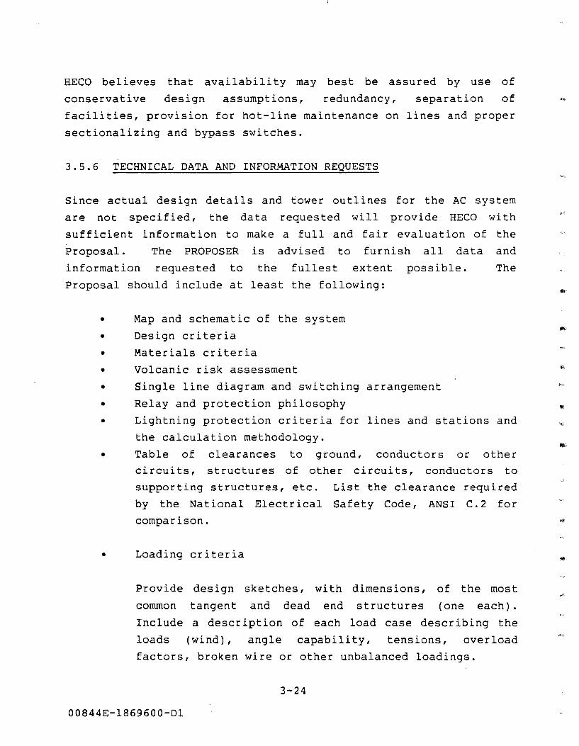
HECO believes that availability may best be assured by use of
conservative design assumptions, redundancy, separation of -
facilities, provision for hot-line maintenance on lines and proper
sectionalizing and bypass switches.
3.5.6 TECHNICAL DATA AND INFORMATION REQUESTS
Since actual design details and tower outlines for the AC system
are not specified, the data requested will provide HECO with
sufficient information to make a full and fair evaluation of the
Proposal. The PROPOSER is advised to furnish all data and
information requested to the fullest extent possible. The
Proposal should include at least the following:
• Map and schematic of the system
• Design criteria
• Materials criteria
• Volcanic risk assessment
• •
Single line diagram and switching arrangement
Relay and protection philosophy
• Lightning protection criteria for lines and stations and
the calculation methodology.
• Table of clearances to ground, conductors or other
circuits, structures of other circuits, conductors to
supporting structures, etc. List the clearance required
by the National Electrical Safety Code, ANSI C. 2 for
comparison.
• Loading criteria
Provide design sketches, with dimensions, of the most
common tangent and dead end structures (one each).
Include a description of each load case describing the
loads (wind), angle capability, tensions, overload
factors, broken wire or other unbalanced loadings.
3-24
00844E-1869600-Dl
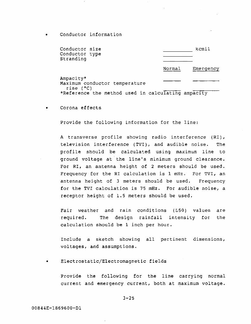
• Conductor information
Conductor size Conductor type Stranding
Ampacity* Maximum conductor temperature
rise (°C)
kcmil
Normal Emergency
*Reference the method used in calculating ampacity
• Corona effects
Provide the following information for the line:
A transverse profile showing radio interference (RI),
television interference (TVI), and audible noise. The
profile should be calculated using maximum line to
ground voltage at ·the line's minimum ground clearance.
For RI, an antenna height of 2 meters should be used.
Frequency for the RI calculation is 1 mHz. For TVI, an
antenna height of 3 meters should be used. Frequency
for the TVI calculation is 75 mHz. For audible noise, a
receptor height of 1.5 meters should be used.
Fair weather and rain conditions (150) values are
required. The design rainfall intensity for the
calculation should be 1 inch per hour.
Include a sketch showing all pertinent dimensions,
voltages, and assumptions.
• Electrostatic/Electromagnetic fields
Provide the following for the line carrying normal
current and emergency current, both at maximum voltage.
3-25
00844E-1869600-Dl
List all assumptions, dimensions and other constants
used in the calculations.
Maximum electric field on the R/W ( kV/m)
Maximum electric field at the edge of the R/W (kV/m)
Maximum magnetic field on the R/W (mG)
Maximum magnetic field at the edge of the R/W (mG)
3.6 HVDC TRANSMISSION SYSTEM
Normal Emergency
The (AC) electric power generated from the geothermal resource is
to be converted to direct current and transmitted to Oahu via high
voltage direct current (HVDC) transmission lines. The basic
transmission plan will utilize a combination of overhead lines and
submarine cables, with. a possible intermediate tap at Maui. The
DEVELOPER may design and construct the transmission system in a
configuration different than that described in the following
paragraphs. This is acceptable as long as the final result meets
the reliability requirements for electric power as outlined in
Section 4. For bid evaluation purposes, however, the PROPOSER
should base costs, component designs and construction principles
on the ratings, routes,
presented in the RFP.
they are identified
converter sites and system configuration
Where specific options are to be quoted,
as such. The PROPOSER may propose
alternatives to the above, provided the requested information is
supplied and the additional information is clearly identified as • 11 Additional 11
•
3-26
00844E-1869600-Dl
3.6.1 GENERAL TRANSMISSION PLAN
The geothermal power transmission system is shown in block diagram
form on Figure 3. 5A. A simplified route map for the system is
shown on Figure 3.5B. These represent the base system
configuration for the Proposal.
The AC collection system between the various geothermal power
production facilities is an overhead transmission system as
described in Section 3. 5. The AC collection system will connect
to a HVDC converter
Figure 3.6C).
terminal in or near the KERZ (see
The HVDC power from the converter terminal (rectifier) may cross
the island of Hawaii via an overhead HVDC line. Two possible
corridors for the overhead line on Hawaii are shown on
Figure 3.6A. The PROPOSER may use either route on Hawaii in
developing the line design and associated costs.
The PROPOSER is also requested to present and cost an option which
would utilize a submarine route around the island of Hawaii along
the eastern shore to the northern tip of the island. This option
is also shown on Figure 3.6A. It will be exercised at the sole
discretion of HECO.
The transmission system will cross the Alenuihaha Channel between
Hawaii and Maui and either cross Maui overhead and exit near Ahihi
or touch down at a point on the southern coast of Maui for
re-pressurizing, if necessary, and continue on to Oahu.
The HVDC transmission system then will traverse the Auau Channel
between Molokai and Lanai and cross the Kaiwi Channel before
terminating on Oahu near Waimanalo where a HVDC converter terminal
(inverter) will be located. It will then connect to the
3-27
00844E-1869600-Dl
HECO 138 kV system at the Aniani Substation, about three miles
from Waimanalo.
3.6.2 CONVERTER AND CABLE TRANSITION LOCATIONS AND TRANSMISSION
LINE ROUTES
The location of equipment and transmission line routes generally
described in Section 3.6.1 are neither fixed nor final. They are
shown on Figures 3.6A, B and C in specific locations for Proposal
purposes only. Mileages between terminations and converter
terminals are approximate. Exact sites and terminal points are
the responsibility of the DEVELOPER.
3.6.2.1 Converter Terminals
The Puna converter terminal (PCT) in the basic system is
tentatively located in the KERZ near the center of the geothermal
resource subzones (GRS). It is identified as PCT on Figure 3.6A.
The exact location of the converter terminal is up to the
DEVELOPER, however, the site shown on Figure 3.6A should be used
in the Proposal as the starting point for the overhead line
options. For the submarine option around the island of Hawaii,
the converter terminal would likely be moved to the east end of
the GRS for practical and economic reasons. This location is also
shown on Figure 3.6A. Photographs of these areas are available in
the public document room for review.
On Oahu, the submarine cables will most likely come ashore at -
Bellows Air Force Base (AFB) near Waimanalo (see Figure 3.6C). A ~
substation site owned by HECO near the corner of Kakaina Street
and Kakaina Place would be the receiving point for the geothermal -,
power on Oahu. The Aniani Substation site is located nearly
midway between the 138 kV substations of Koolau and Pukele and
close to an existing 46 kV right-of-way. The converter terminal
could be located anywhere in the area around Aniani, possibly
3-28
00844E-1869600-Dl
including a possible site on the northern end of Bellows AFB,
which is no longer an active flying facility.
3.6.2.2 Overhead Transmission Line Routes
There are three segments of the HVDC transmission system which may
involve overhead transmission lines. The length and exact routing
are variables depending on the final location of the converter
terminals and transition stations. The base system includes:
• A line from the Puna converter terminal to the north end
of Hawaii in the North Kohala District where an exit
transition station would be located, a distance of
approximately 131 miles.
• A line from a landing transition station on the south
shore of Maui, possibly near Huakina Bay, to an exit
transition station south of Maalaea, perhaps near Ahihi
Bay, a distance of approximately 20 miles.
At the PROPOSER'S option there may be a third overhead segment:
• A line on Oahu from a converter terminal near the shore
to Aniani Substation, a distance of about three miles.
The line from Puna to North Kohala could take at least two
different routes, the shortest being up through the saddle betw.een
Mauna Loa and Mauna Kea at altitudes above 6000 feet. An
alternate route is along the northeastern shore on the slopes of
the Hamakua coast. Both routes are shown on Figure 3.6A and the
PROPOSER may use either in costing the base Proposal.
The overhead HVDC line on Maui could run parallel to the southern
coastline, probably below the Piilani Highway, but above the Kings
Trail (See Figure 3.6B).
3-29
00844E-1869600-Dl
3.6.2.3 Submarine Cable Routes
The first segment of submarine cable would cross the Alenuihaha
Channel between Hawaii and Maui", a distance of about 42 miles at a
maximum depth of nearly 7200 feet. Considerable bathymetric data
has been gathered on this portion of the submarine cable route,
and is available for review in the public document room (see
Appendix B, Section B.2.2.1 and Figure 3.6D).
Depending on the type of oil-filled cable proposed, pressurized or
non-pressurized, a landing on Maui may not be necessary for
technical reasons. Note, however, that the base system requires
the PROPOSER to cost out in-and-out terminations on Maui. If ....
necessary, a converter terminal could be located near the south
shore and the HVDC cables brought in and taken out at the same
site.
The second segment of submarine cable would follow the Alalakeiki,
Auau, and Kalohi channels between Maui, Kahoolawe and Lanai past
Molokai, crossing the Kaiwi Channel to Oahu. The landing on Oahu,
as mentioned earlier, would likely be in the vicinity of Waimanalo
on the windward or eastern shore of Oahu. This submarine cable
length is about 96 miles, with a maximum depth less than 2400
feet.
3.6.2.4 Cable Transition Stations
Transition stations will be necessary wherever the electric power
transmission changes from overhead line to submarine cable or vice
versa. Depending on the exact overhead route taken for the base
system, the line could exit the island of Hawaii somewhere on the
North Kohala shore, possibly near Muhakona Harbor. A transition
station would, therefore, be necessary on Hawaii before the
submarine crossing to Maui. For the option of a submarine cable
around Hawaii, a transition and pressurizing station in and out
3-30
00844E-1869600-Dl
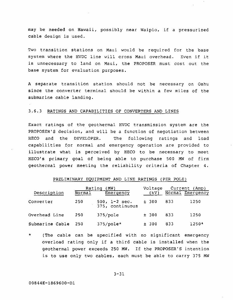
may be needed on Hawaii, possibly near Waipio, if a pressurized
cable design is used.
Two transition stations on Maui would be required for the base
system where the HVDC line will cross Maui overhead. Even if it
is unnecessary to land on Maui, the PROPOSER must cost out the
base system for evaluation purposes.
A separate transition station should not be necessary on Oahu
since the converter terminal should be within a few miles of the
submarine cable landing.
3.6.3 RATINGS AND CAPABILITIES OF CONVERTERS AND LINES
Exact ratings of the geothermal HVDC transmission system are the
PROPOSER'S decision, and will be a function of negotiation between
HECO and the DEVELOPER. The following ratings and load
capabilities for normal and emergency operation are provided to
illustrate what is perceived by HECO to be necessary to meet
HECO' s primary goal of being able to purchase 500 MW of firm
geothermal power meeting the reliability criteria of Chapter 4.
PRELIMINARY EQUIPMENT AND LINE RATINGS (PER POLE)
Rating (MW) Description Normal Emergency
Voltage (kV)
Converter 250 500, 1-2 sec. ± 300 375, continuous
Overhead Line 250 375/pole ± 300
Submarine Cable 250 375/pole* ± 300
Current (Amp) Normal Emergency
833 1250
833 1250
833 1250*
* (The cable can be specified with no significant emergency
overload rating only if a third cable is installed when the
geothermal power exceeds 250 MW. If the PROPOSER'S intention
is to use only two cables, each must be able to carry 375 MW
3-31
00844E-1869600-Dl
continuously. See Section 3. 6. 6. 4 for a discussion of the
required switching capability.)
It should be emphasized that the use of 125, 250 and 375 MW for
intermediate power levels and a transmission voltage of ± 300 kV
are illustrative only and should not be regarded as fixed or final
values even for the response to the RFP. The Proposal schedule
(Exhibit 5.3A) for reaching 500 MW of capability by 2005 for all
production and delivery elements is the responsibility of the
PROPOSER.
3.6.3.1 Operating Requirements
While specific HVDC voltage and power ratings have been mentioned
in this description of the HVDC transmission system, it is
incumbent on the DEVELOPER to select the actual system voltage and
power transfer capabilities. The ratings proposed in this
specification should be used in responding to the RFP. However,
options may be included for other levels which in the PROPOSER'S
opinion may improve reliability, operating flexibility, or
economics.
For the Project, power is defined as the AC power measured at
Aniani Substation on HECO's 138 kV system.
Voltage for the Project is defined as the AC voltage measured at
Aniani Substation on the HECO system.
When a power or voltage rating is a requirement, the power and
voltage rating will be considered in compliance when they exist:
• over the complete range of ambient or atmospheric
conditions described;
3-32
00844E-1869600-Dl
. ..
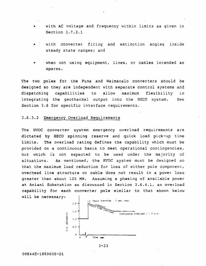
• with AC voltage and frequency within limits as given in
Section 3.7.2.1
• with converter firing and extinction angles inside
steady state ranges; and
• when not using equipment, lines, or cables intended as
spares.
The two poles for the Puna and Waimanalo converters should be
designed so they are independent with separate control systems and
dispatching capabilities to allow maximum flexibility in
integrating the geothermal output into the HECO system. See
Section 3.8 for specific interface requirements.
3.6.3.2 Emergency Overload Requirements
The HVDC converter system
dictated by HECO spinning
emergency overload requirements are
reserve and quick load pick-up time
limits. The overload rating defines the capability which must be
provided on a
but which fs
situations.
continuous basis to meet operational contingencies,
not expected to be used under the majority of
As mentioned, the HVDC system must be designed so
that the maximum load reduction for loss of either pole component,
overhead line structure or cable does not result in a power loss
greater than about 125 MW. Assuming a phasing of available power
at Aniani Substation as discussed in Section 3.6.4.1, an overload
capability for each converter pole similar to that shown below
will be necessary:
2.0 I r Fault Override 1 sec. min.
l.S "' '- Continuous overload ~ L.5 p.u. ;;: :;: l.O ., <.:
"' ::;:
;:, 0.5
;:..
0 Time-
3-33
00844E-l869600-Dl
The PROPOSER should define and quantify the overload capability of
all major components in the HVDC transmission system including,
but not limited to, the following:
• Puna converter terminal
• Overhead transmission lines
• Submarine transmission cables
• Cable terminations
• Waimanalo converter terminal
See Section 3.8 for specific interface requirements.
3.6.4 CONVERTER TERMINALS
The following are general comments concerning the configuration
and operating modes of the HVDC system:
The Puna and Waimanalo converters should be full bipoles with two,
six-pulse bridges connected in series on each pole, which will
make it easier to schedule installation of the DC system to match
the development of the geothermal resource.
The Puna converter will operate as a rectifier and the Oahu
converter as an inverter. Under these configurations power
transfer will always be from Hawaii to Oahu (500 MW).
3.6.4.1 Operating Modes
Possible operating modes for the HVDC system include:
Balanced Bipolar
Unbalanced Bipolar
Monopolar Sea Return
00844E-1869600-Dl
3-34
One possibility for the sequence of construction, operating modes
and approximate MW and voltage ratings for the Hawaii and Oahu
converters is as follows:
Phase I 125 MW, + 150 kV, monopolar
Phase II 250 MW, ± 150 kV, bipolar
Phase III - 375 MW, + 300 kV, -150 kV bipolar
Phase IV 500 MW, ± 300 kV, bipolar
While the DEVELOPER has some flexibility in scheduling the
geothermal power development, the above sequence is primarily
driven by HECO's spinning reserve and reliability requirements as
discussed in Chapter 4 and power requirements, as outlined in
Section 5.1. The schedule submitted on Exhibit 5.3A should
include the converter configuration.
3.6.4.2 Equipment Data and Information
The details of equipment design and final ratings are the
responsibility of the DEVELOPER subject to HECO evaluation as
deemed necessary to meet the HECO power requirements and
reliability as set forth in this RFP. For the converter terminal,
the PROPOSER should supply design data and information according
to the following list for evaluation purposes:
• DC system one-line diagram
• Converter terminal layout drawings
• Converter terminal plan and elevation drawings
• Converter transformers
• AC filters
• AC reactive supply
• Valve hall layout
• Valve design details and single line diagram to the
thyristor level
3-35
00844E-1869600-Dl
• Valve control system (effect of cable)
• Valve cooling system
• All surge arresters, AC and DC
• Smoothing reactors
• DC filters
• Neutral bus arrangement
• Neutral grounding system
In addition, the PROPOSER should submit sufficient information to
verify that the proposed converter terminal designs meet the power
transfer and voltage requirements set forth in this RFP. This
information includes:
• For each converter terminal:
•
Transformer impedance
Rated no-load voltage, Udon
Nominal firing angle
Nominal extincition angle
Converter equation
Steady-state range of firing angles
Steady-state range of extinction angles
Maximum no-load voltage (Udo maximum)
Minimum no-load voltage ( udo minimum) and related
system operation condition
Maximum pole-to-neutral voltage
Maximum pole-to-ground DC voltage
Minimum pole-to-neutral DC voltage and related
system operating condition
Transformer load tap changer percent range and
number of steps
Illustrative examples of system power transfer
condition, associated system voltage profiles and
converter terminal conditions. Those system operating
configurations, operating modes and system power level
3-36
00844E-1869600-Dl

dispatches which dictate load tap changer ranges and/or
converter angle operating ranges shall be included.
• Converter terminal and DC
capabilities and associated
system reduced voltage
DC current capabilities.
• Information on the voltage ranges which may be expected
at the converter terminals during minimum current
operation.
3.6.4.3 AC and DC Harmonics and Harmonic Filters
The design and performance of both AC and DC harmonic filters is
the responsibility of the DEVELOPER. The general criteria set
forth herein are estimates of minimum levels which should be met
in order to assure HECO that there will be no harmonics introduced
either into the AC systems at converter terminals or from coupling
into AC circuits or other electrical facilities along the route of
the HVDC transmission system.
a. AC Harmonic Filters
The DEVELOPER shall furnish AC harmonic filters, segregated
with one set of filters per converter pole bus. The AC
filters shall perform properly when taking into account the
combined effects of:
• Harmonic current generation from the converters and
static compensators (if used) at the converter terminal,
• Induced 60 Hz effects from any parallel AC lines,
• Electrical and environmental conditions as described in
Section 3.7.
3-37
00844E-1869600-Dl
Because of the impact on the HECO AC system of harmonic generation
by the converter, the DEVELOPER will be required to minimize the
effect by proper design of the AC filters. The PROPOSER should
provide sufficient information from study results modeling both
the HECO AC system and the proposed HVDC transmission system to
demonstrate that the PROPOSER has a thorough understanding of all
factors which contribute to harmonic interference.
The PROPOSER should include discussions of the following areas in
the Proposal:
• Definition of normal and contingency ratings
• Assumptions for harmonic generation
• Imbalance considerations
• Simulation or equations used in calculating generated AC
harmonic currents
• Filter detuning
• Effect of loss of one filter on the calculation
The estimated AC harmonic performance criteria are as follows:
Individual Distortion Total Distortion Telephone Interference Factor Ieq (mA-RMS)
b. DC Harmonic Filters
Normal Operation
1.0 percent 2.0 percent
35 400
Contingency Operation
1.5 percent 3.0 percent
50 400
The PROPOSER should adopt a comprehensive system-level design
approach to determine the final DC harmonic filter
requirements for all of the HVDC system converter terminals.
The primary design criterion shall be based on limiting
interference to voice-frequency communication circuits which
may be located adjacent to the DC transmission line.
3-38
00844E-1869600-Dl
..,,
..,,
Design of the DC harmonic filters shall take into account the
combined effects of:
• All modes of operation for all possible DC system
operating configurations.
• Induced 60 Hz effects from any parallel AC lines. The
effects on harmonic generation or propagation of any
special equipment included in the Proposal to deal with
this issue shall also be considered, such as 60 Hz
filters or specific control strategies.
• The electrical and environmental conditions described in
Section 3.7.
The PROPOSER should provide sufficient information from study
results to demonstrate that the PROPOSER has a proper
understanding of all factors and has performed the studies
necessary to support the proposed design of the DC harmonic
filters for the Project's converter terminals. The PROPOSER is
solely responsible for determining the DC system operating
configurations which establish the worst-case conditions for
design of the DC filters.
To allow proper evaluation of the DC filter designs and their
performance, the PROPOSER will also provide the following
information in the Proposal:
• Description of DC filter performance
• Evaluation method (Calculation of equivalent disturbing
current, Iq)
• DC system modeling
• Harmonic generation assumptions
• Filter detuning assumptions
• Calculation results in tabular form
3-39
00844E-1869600-Dl
The DC filter designs, when the system is in bipolar operation,
should result in ·an Iq equal to or less than 200 rnA rms anywhere
along the DC transmission line. When in monopolar operation, the
system is not required to meet this value, however, the PROPOSER
should calculate and present the results for monopolar operation
of the system.
3.6.4.4 Reactive Compensation and Voltage Control
The DEVELOPER shall furnish all necessary reactive compensation
and voltage control equipment for the Waimanalo converter terminal
based on requirements of this RFP. The subject equipment may
include any combination of AC harmonic filters, shunt capacitors,
shunt reactors, static var compensators and/or synchronous
condensers. The PROPOSER is not restricted to this list.
The reactive compensation equipment should also include all
necessary circuit breakers, switches, isolators, protection and ""
measurement/control devices.
The reactive compensation equipment should be an optimal
combination of components and controls that will satisfy the
reactive needs of the DC converters and the HECO AC system while
considering installed costs, filter requirements, and the power
delivered to the HECO system.
a. Steady State Reactive Requirements of the HECO AC System
The reactive requirements of the HECO system are a function
of the AC load level and operating conditions and the level
of HVDC system power transfer. For the purposes of the
response to the RFP, the PROPOSER should assume that by 2005
the HECO system will require an additional VAR supply of 310
MVAR at a nominal voltage of 138 kV, which corresponds to the
MVAR capability of a 500 MW conventional power source
3-40
00844E-1869600-Dl
operating at 85% leading power factor. While the final AC
system design may require the 310 MVAR to be split into
smaller banks and located at other substations on the HECO
system, the PROPOSER should assume the AC system VARS will be
located at the Waimanalo Converter Terminal and installed by
the DEVELOPER.
A voltage support study of the 138 kV system will be
performed by HECO. The results will be available to the
DEVELOPER for final design purposes.
b. Reactive Demand of the Converter Terminals
The DEVELOPER is responsible for providing at a minimum
sufficient reactive supply to compensate the converters
reactive requirements to unity power factor across the total
power output range of the converter terminal. The PROPOSER
should state the minimum power level (monopolar) in the
Proposal design and discuss how it ~as determined.
c. Steady State and Transient Voltage Control
The reactive compensation system elements should be used for
steady-state AC voltage control. An automatic AC voltage
control function should be provided which will receive
operator unit input settings which will maintain voltage
between the limits shown in Section 3.7.2.1.
The DEVELOPER should provide automatic controls for switching
and/or otherwise controlling the reactive compensation so as
to maintain the steady-state voltage at the Aniani Substation
138 kV bus within an adjustable bandwidth.
Normally, the voltage will be maintained within the range
1.01 per unit (p.u.) to 1.04 p.u. through automatic control.
3-41
00844E-1869600-Dl
This should be achievable, for example, by operator selection
of 1.01 p.u. as the lower limit and by selecting an
appropriate bandwidth.
To minimize voltage flicker, the transient change in the
fundamental frequency component of voltage on the Aniani
Substation 138 kV bus should not exceed 1 percent (.01 p.u.)
for more than 1-1/2 cycles when a shunt capacitor, harmonic
filter bank or shunt reactor bank is switched.
The above requirement should apply at all relevant DC system
power transfer levels and the normal short-circuit capacity
level as defined in Section 3.7.2.2. This requirement should
also be satisfied when any one of the HECO 138 kV lines
terminating at Aniani Substation is out of service.
The MVAR rating of all swi tchable capacitor banks and AC
harmonic filter banks should be limited, as required, to be
consistent with voltage drop requirements as stated. The
PROPOSER should specify the appropriate switching equipment.
All circuit breakers or load break switches used for
switching capacitors and filters should be capable of
disconnection or energization of any bank, with the other
banks energized without restriction. There should be no
limitation on the energization of any shunt bank by reason of
temperature, frequency, or AC bus voltage within the range •
applicable for valve group operation.
3-42
00844E-1869600-Dl
d. PROPOSER Requirements
The PROPOSER should describe his complete philosophy on
reactive compensation and voltage
discussion on the following subjects:
control including
• Reactive compensation and voltage control studies
• Load flow studies
• Dynamic simulation studies
• Reactive compensation system design
• One-line diagram of reactive compensation scheme with
all equipment identified
• Calculation of reactive requirements
• Reactive absorption requirements, if any, and equipment
or control strategy used to satisfy requirements
• How steady-state voltage will be achieved
• Minimizing voltage flicker when switching
• Availability and contingency philosophy
3.6.4.5 Insulation Coordination
The insulation coordination of a HVDC converter terminal is
critical to the reliability and cost of the terminal, more so than
in an AC substation. The PROPOSER is expected to complete a
preliminary insulation coordination study for the AC swi tchyard
(including the AC side of the inverter transformer), the thyristor
valves and the DC switchyard. The study should result in
determination, on a preliminary basis, of insulation withstand
values for all voltage levels, surge arrester protective levels,
protective margins, arrester ratings, arrester dimensioning, and
energy discharge requirements.
The study can utilize digital computers or a combination of
digital and analog simulators if desired. Basic assumptions used
in the study should be discussed and included in the Proposal.
3-43
00844E-1869600-Dl
The AC and DC system events which produce overvol tage deemed
critical by the PROPOSER and on which his insulation coordination
is based should be discussed and a rationale included for
evaluation purposes. System events which should be considered in
the determination of the critical events should include, but are
not limited to, the following:
• HECO AC system faults
• Load rejection
• Converter terminal AC faults
• Valve hall faults
• DC switchyard faults
• • • •
Control malfunctions
DC line faults
Switching surges
Lightning surges
• Dynamic overvoltages
A summary of the results of the insulation coordination should be
included with the Proposal, preferably in tabular form.
3.6.4.6 HVDC System Studies and Testing
The DEVELOPER shall perform, during the detailed design phase,
steady-state studies of the DC system in sufficient detail to
ensure that all of the requirements for system
voltage set forth in this RFP have been met.
must be approved by HECO before release
manufacture. A description of these tests and
performed should be included in the Proposal.
power transfer and
The study results
of equipment for
where they will be
The PROPOSER shall
also describe in the Proposal a series of verification tests which
will be performed after the above design tests are completed. The
facilities to be used for the verification tests should also be
described in full detail. The verification tests should include,
but not be limited to, the following areas:
3-44
00844E-1869600-Dl
Steady state control performance
Transient control performance
Stability
Insulation coordination
Harmonic filters
Reactive compensation
3.6.5 OVERHEAD HVDC TRANSMISSION LINES
This RFP has identified two line segments using HVDC overhead
transmission in the base plan. The first is across Hawaii and the
second across the southern end of Maui. The PROPOSER is requested
to treat these overhead line segments in the base system as
required, regardless of whether the preferred approach is the same
as the base system or not. Modifications to the base system may
be included as options.
The PROPOSER is free to design the overhead line structure and
conductor configuration as desired, as long as th~y are in
compliance with the NESC and State of Hawaii General Order No. 6.
To be consistent with HECO system requirements presented in
Section 3.6.3, each pole conductor of the overhead line sections
must be capable of carrying 375 MW in the event of the loss of the
conductor for the other pole. For the base proposal, the
assumptions presented in Sections 3.6.3 and 3.6.4.1 should be
followed by the PROPOSER in designing and dimensioning the HVDC
overhead line sections.
3.6.5.1 Structural Design Guidelines
The HVDC transmission structures for the ± 300 kV line can be wood
pole, steel pole, lattice self-supporting or guyed lattice. The
bipole line could use two monopole structures or a single bipole
structure. The decision as to which of these structure types or
configurations is used is a function of economics, reliability,
3-45
00844E-1869600-Dl
•
and schedule requirements, which the PROPOSER should consider in
responding to this RFP. Meteorological and atmospheric data for
Oahu, Hawaii and Maui is given in Section 3.7.1 and can be used
for preliminary criteria for both structural and electrical design
as needed.
• The structural design should utilize loading criteria
for the state of Hawaii and in particular the islands of
•
Hawaii and Maui. The information below is presented for ~
reference only:
NESC light loading district NESC extreme wind load of 145 fps Maximum wind speed of 88 fps Seismic Zone 3
Preliminary sketches showing conceptual structural
aspects of the major tower types should be included with
the Proposal. These sketches should include all
pertinent dimensions, such as tower height, width at
base, crossarm width, shield wire height above crossarm,
crossarm height above ground and loading capability.
• Design criteria used in developing the tower types and
dimensions and foundations should be stated in the
Proposal.
• Some data on soils along the preliminary routes is
available in the public document room. The DEVELOPER
must obtain actual data through soil borings and land
surveys for final design purposes.
3.6.5.2 Electrical Design Guidelines
The electrical design aspects of the HVDC ± 300 kV overhead
transmission line include conductor selection, insulator
3-46
00844E-1869600-Dl
selection, clearances, shielding, grounding, corona, field effects
and free ion movement. With the exception of ion drift there is
little, if any, difference between AC and DC transmission lines in
terms of design criteria, either structurally or electrically.
Conductor selection should include consideration of the HVDC
conductor thermal limits based on ambient air temperature and
corona level. Requirements on overload capability are detailed in
Section 3. 6. 4. 3 and ambient temperature ranges are presented in
Section 3.7.1. If the overhead line route selected by the
PROPOSER is through the saddle between Mauna Loa and Mauna Kea on
the island of Hawaii, consideration should be given to the high
altitudes (above 6000 feet) and their effect on corona start
voltage.
Insulator selection, both number per pole an·d contour should be
carefully analyzed by the PROPOSER. Salt contamination is severe
in some locations where overhead lines could be routed. The
experience with AC in those same areas has required not only fog
type insulator units with higher leakage than conventional units,
but sometimes more units per string. The PROPOSER should consider
all reasonable possibilities for improving insulator performance
over routine design, including the use of vee string
configuration, special DC ceramic insulators and polymer
non-ceramic units. The PROPOSER must provide complete details on
the insulator selection process and tests to be performed by the
DEVELOPER to verify insulator selection and performance.
Clearance, shielding and grounding design are essential elements
to consider in order to obtain adequate lightning performance and
to meet NESC and State of Hawaii requirements for safety. The
PROPOSER should include with the Proposal all design criteria and
calculations involving comparisons to NESC and State requirements,
including predicted outage rates per 100 miles per year for the
transmission line design proposed.
3-47
00844E-1869600-Dl
Corona effects are related to conductor size, span length, and
clearances to grounded objects. The PROPOSER should include in
his response a discussion of the levels of corona and its direct
effects on radio noise, television interference and audible noise
expected with his design. A discussion of the calculation methods
and assumptions utilized should be included. Data should be given
at nominal voltage and at ten percent above nominal voltage.
Electric and magnetic field effects under and near HVDC
transmission lines are essentially the same as produced under AC
lines except for the lack of a time varying electromagnetic field.
Thus, electric fields under or near DC lines cannot produce
current flow in objects under or near the lines. The PROPOSER
should provide electric and magnetic field profiles for the
proposed line design under the line and to the edge of the
right-of-way. Any interaction effect from other electric power
lines on the same right-of-way should be included in the results.
Free ion movement in the vicinity of HVDC lines is not known to
create a hazard to human or animal health, however, the PROPOSER
should include a discussion of the subject as a function of his
HVDC line design.
3.6.6 SUBMARINE CABLE
Submarine cables have been researched and the results are
documented and part of the data available to the PROPOSER.
The research program covered the following subjects in detail:
Cable Design Criteria
Route Identification
At-sea Route Surveys
Bathymetric Surveys
Environmental Survey
00844E-1869600-Dl
Cable Design Parametric
Economics
Manufacturing and Transport
Cable Laying and Retrieval
Vessels
3-48
Studies
•·
Sediment, Wave Motion
and Ocean Current
Measurements
Laboratory Test Protocol
At-sea Test Protocol
The cable research results are summarized below. HECO does not
represent that this information is a complete summarization of all
existing documents. The summary is provided only for the
PROPOSER'S information.
• Based on presently available information, there appear
to be cable designs which satisfy the defined system
requirements and en vi ronmen tal conditions which affect
deployment, retrieval and repair of a commercial cable
for this Project.
• Technical feasibility appears achievable by the
application of existing state-of-the-art design for
conventional self-contained submarine cables,· either
pressurized or non-pressurized.
• Extensive surveys of the sea environment have been
conducted to determine the details of the bottom on one
cable route, velocities of the currents in the
Alenuihaha Channel from the surface to the bottom, wind
velocities and wave heights. A procedure for testing a
candidate cable was developed, incorporating both CIGRE
tests and tests reflecting the specific conditions found
on this cable route. As a result of these tests, the
reports summarized have concluded that it is feasible to
design, manufacture, and install a cable that can
withstand the mechanical loads resulting from installa
tion and operation for a thirty years life under the
environmental conditions examined. The reports
describing the tests, test procedures and results are
listed among the references for this RFP. A report on
3-49
00844E-1869600-Dl
•
at-sea test results with a surrogate cable is expected
to be available by March, 1990.
• Cable designs using aluminum conductors are available
that accommodate reasonable ranges of external and
internal mechanical stresses and fulfill the Project's
electrical requirements.
• The technical data and information available permits
assessment of reliability, manufacturing feasibility,
design requirements for installation and recovery
vessels, design of cable handling equipment, costs and
fabrication schedule.
Selection of the cable type or types is the PROPOSER'S
responsibility. The PROPOSER should describe fully the philosophy
and rationale involved in the cable selection process. In
addition, each of the cable mechanical and electrical design
parameters described briefly in the following section should be
included in the Proposal. A more· detailed treatment of these
parameters may be found in the cable design parametric study for
the Hawaii Deep Water Cable research program, Call No. 119 of the
Bibliography. The PROPOSER should -indicate how it will be
demonstrated that the proposed cable design(s) can withstand the
mechanical and electrical loads defined in the Laboratory Test
Protocol, Call No. 118 of the Bibliography.
3.6.6.1 Basic System Criteria
For the purposes of this RFP, the following system criteria should
be considered for the base Proposal.
Transmission configuration
00844E-1869600-Dl
3-50
Monopolar to full bipole (See Sections 3.6.3 and 3.6.4.1)
Number of cables
Cable voltage rating
Load capability (per cable)
Overvoltage (transient)
Overvoltage (steady state)
Polarity reversal
Two or three (one spare)
Final ± 300 kV DC
Two cables 375 MW each or if three cables 250 MW each
PROPOSER responsibility
PROPOSER responsibility
PROPOSER responsibility
There are a number of physical and topographical design criteria,
some of which are specified as part of the base bid and others
which are the PROPOSER'S responsibility. These are:
Minimum spacing between
cables
Number of cable splices
and termination
Continuous length of cable
Maximum water depth
. PROPOSER Responsiblity
PROPOSER Respansiblity
42 miles and 96 miles
7200 ft
Possible cable routes for this RFP, including the option around
Hawaii, are described in Section 3.6.2.4. Bathymetric studies
have been completed for the route from Hawaii to Maui across the
Alenuihaha Channel and between Maui (Ahihi) and Oahu. These
studies are available for review in the public document room.
Depths for the Alenuihaha Channel from Hawaii to Maui are shown in
Figure 3.6F.
The optional cable route around the island of Hawaii to Kohala has
not been studied in detail, nor has the area around La Perouse Bay
on the Maui southwest shore. The latter appears to have two
potential problems; first, the sea bottom may be both rough and
unstable, and the cable may require burial to avoid damage, and
second, the area is part of the Ahihi-Kinau Natural Area Reserve,
which extends out some distance from the shore.
3-51
00844E-1869600-Dl
Surface and subsurface conditions which affect cable performance
and ratings are external parameters which should be considered and
quantified for verification purposes. These include the maximum
surface water temperature, the seabed ambient temperature, the
seabed thermal resistivity, the depth of sedimentation coverage,
the seabed profile, and the subsurface currents.
Information on these parameters may be found in the Bibliography.
They should be considered when calculating the average conductor
resistance for evaluating the cable losses at rated current and
for conducting the necessary hydraulic analyses for design
purposes. The loss calculation result should be provided in
average loss per unit length (kW/ft).
3.6.6.2 Cable Design Parameters
The cable design parameters listed below ar.e for reference only
and are not all-inclusive. The PROPOSER should describe the cable
or cables intended for use in the base Proposal using cable
lengths and designs which reflect the basic system criteria in
Section 3.6.6.1, and provide values for each of the cable design
parameters listed.
Basic cable design parameters to describe the cable system
proposed include:
• Cable type or types
• Conductor material
• Conductor design
• Conductor size in sq. mm and cir. mils.
• Oil duct size (if needed)
3-52
00844E-1869600-Dl
• Major insulation materials
• Dielectric fluid
• Sheath materials
• Armor design
• Maximum allowable electrical stress
• Maximum allowable temperature of conductor
• Maximum allowable temperature different-ial between
conductor and ambient for three sea locations using the
given ambient temperatures for reference and Proposal
purposes only:
Sea location · Ambient oc op.
Deep (>2000 ft) 3 37
Intermediate (200 - 2000 ft)
Near Shore (100 - 200 ft)
14
25
57
77
The PROPOSER should provide a detailed description of the cable
type or types based on the elements of the cable construction
identified in the following list. A cross-sectional graphic
presentation of the cable should be included, with each element
identified and element thickness specified.
Conductor Sheath
Conductor shield Jacket tapes
Insulation Bedding, binding and serving
Insulation shield Armor
3-53
00844E-1869600-Dl
Core protection Corrosion protection
3.6.6.3 Design Constraints
There are thermal, electrical, and mechanical constraints inherent
in the selection of submarine cable which must be carefully
considered at the design stage, particularly if there is any
deviation from accepted practice. Both electrical and mechanical
design safety factors should be discussed and tabulated in the
Proposal. The PROPOSER should discuss each of the constraints
listed below and describe how, in the proposed design or designs,
each has been accommodated:
a. Thermal constraints
• Maximum allowable conductor temperature
• Maximum allowable temperature differential
b. Electrical constraints
• DC voltage stress
• Transient overvoltage
• Steady state overvoltage
• Polarity reversal
• Polarity reversal followed by overvoltage
• Impulse strength
c. Mechanical constraints
• Water pressure at depths expected to be encountered
in this project
• Crushing load during installation
• Thermal cycling effects on sheath integrity
3-54
00844E-1869600-Dl
• Deployment and retrieval tensions
• Distribution of pulling tensions
• Maximum allowable pulling tensions
• Maximum allowable cable elongation during
installation and retrieval
• Minimum cable bending diameter
d. Miscellaneous constraints
• Hydraulic pressure (pressurized cables only)
• Cable length
• Sea bottom profile
• Slope
3.6.6.4 Switching, Splicing, Termination and Auxiliaries
The PROPOSER shou·ld include a detailed description of splicing
techniques and termination design to be used, particularly if
different types of cable are to be spliced anywhere on the route.
A conceptual layout of the submarine cable route should be
included in the Proposal showing splice locations, termination
stations, pressurizing stations, sectionalizing stations and
switches for rapid transfer to the spare cable in case of a cable
fault.
Switching
If the overload capability and reliability required for the
submarine cable when at the maximum capacity of 500 MW is met by
use of three cables, the DEVELOPER must include means of quickly
switching out a faulty cable to minimize time at reduced power.
The PROPOSER should show a single line diagram of the switching
scheme, the type of switches to be used, and an estimate of the
time required to isolate a faulted cable and restore full power.
3-55
00844E-1869600-Dl
•
A rationale for switching scheme, including configuration for the
three cables should be provided.
3.6.6.5 Manufacturing, Transport and Installation
Although the projected diameter of the cable is not unusual, the
length and depth of the route may pose significant challenges in
transport and installation. It appears that the manufacturing
capability without splices, and the shipping length with minimum
splices, may be critical elements in accomplishing the successful
installation and operation of the cable. The PROPOSER should
present a complete description of the following:
• Manufacturing capability including maximum cable length
and feet/month possible by the proposed manufacturing
facilities.
• Location of the cable manufacturing facilities .
• Shipping capability; i.e., length of cable on storage
turntable, and number of splices per shipping length.
• Cable installation plan including transport, identifi
cation of transport and installation vessels, and
proposed schedule for cable installation.
• Cable retrieval and repair procedure.
3.6.7 HVDC NEUTRAL GROUNDING SYSTEM
The HVDC transmission system will require neutral grounding at
Puna and Waimanalo, and possibly at Maui. The ground return
system can be designed in several ways: as an embedded ground
electrode; as a sea electrode, either on shore or a short distance
off shore; or as a dedicated metallic conductor on the pole line
3-56
00844E-1869600-Dl
•
....
structure for overhead lines and using a separate cable for
submarine sections.
For a three cable system, the ground return system for the Puna
and Waimanalo converters must be capable of carrying 833-1250
amperes continuously since the system will likely operate in the
monopolar configuration in the initial phase. In the third phase
(See Section 3.6.4.1), the system may operate in an unbalanced
bipolar mode, again resulting in significant current in the
neutral. In a balanced bipolar system, the maximum normal neutral
current is only one or two percent of the pole current or 10 to 25
amperes. The neutral will only carry full load current during
temporary monopolar operating conditions.
The PROPOSER should consider all types of ground return designs
and decide which should be employed at each converter for the base
Proposal. The following information may be used for guidance;
however, the DEV~LOPER is responsible for obtaining detailed local
data for ground return design.
3.6.7.1 Ground Electrodes
Ground electrodes are most efficient and cost effective when the
earth resistivity in the vicinity of the converter is 150
ohm-meters or less. The earth resistivity on Oahu near Waimanalo
is estimated to be about that level, although no measurements have
been taken recently. The PROPOSER must consider interference
effects on nearby electrical facilities and pipelines if a ground
electrode is planned, and discuss proposed mitigating measures and
procedures. A layout of any proposed ground electrode, with
dimensions, should be included in the Proposal, bearing in mind
that the ground electrode should be at least 2.5-3.0 miles from
the converter terminal.
3-57
00844E-1869600-Dl
The earth resistivity of the KERZ is very high, above 2000 to
3000 ohm-meters. This high resistivity probably means that a
ground electrode cannot be used because of severe cost penalties
and interference problems.
3.6.7.2 Sea Electrode
An alternative to the ground electrode is the sea electrode, if
access to the sea is available within a reasonable distance from
the converter. A sea electrode can be constructed either at the
shoreline or a short distance ~ff-shore. The converter is likely
to be only a short distance from the sea for each location for the
Project. There may be a problem at Waimanalo in obtaining
sufficient separation between the converter and the sea electrode
to avoid interference. If the PROPOSER selects a sea electrode
for this application, a conceptual design sketch and layout should
be included with the Proposal. While a sea electrode may have
some distinct advantages over a ground electrode, precautions may
need to be taken to prote.ct fish and sea life in the area and to
avoid siting the facility near a public beach or recreational area
for safety and aesthetic reasons.
3.6.7.3 Metallic Return
A metallic return involves adding a fourth cable to the HVDC
submarine segments of the transmission line and a third conductor
to the overhead portions. It also means starting initially with "'
two cables rather than the one which would be possible with either
a ground or sea electrode system. The cost of using a metallic
return may be too high to compete with the other options; however,
this decision is the PROPOSER'S choice and responsibility.
3-58
00844E-1869600-Dl
3.6.8 HVDC SYSTEM CONTROL AND PROTECTION
The operation, control and protection of the HVDC system is the
responsibility of the DEVELOPER. However, to ensure that the HVDC
system will operate properly with HECO's system, HECO desires that
the HVDC system control and protection be designed with the
following primary considerations.
• The control and protection system should be flexible to
allow adjustments and modifications to control and
protection strategies as both DC and AC system operating
needs change.
• Control and protection strategies should be secure, with
minimum false operations. Schemes to protect equipment
should be fail-safe, and should rely only on locally
measured quantities. Remote signals may be used to
improve selectivity and sensitivity
actions and recovery from faults, but
required to complete or initiate
equipment.
of protective
should not be
protection of
• Control and protection strategies should be consistent
among all converter terminals, wherever possible.
• The control and protection system should be as simple as
possible, while meeting all functional requirements.
• All equipment should be self-protected within each
converter terminal.
The PROPOSER must explain the hierarchy of the control system
proposed and relate it to the overall system operation identified
in the Proposal, consistent with HECO reliability requirements.
3-59
00844E-186~600-Dl
The PROPOSER should identify all HVDC control system communication
requirements and list those which will have to be integrated into
the HECO communication and dispatch network and those which will
be only used in the DEVELOPER'S system.
In addition, for evaluation purposes, the PROPOSER should discuss
the following features of the control system proposed:
a.
• available control modes
• automatic or manually controlled equipment, such as
filters and capacitor banks
• polarity reversal
• converter transformer tap changers
• coordination between terminals
• command orders between terminals
• special contingency control, such as runback schemes
• subsynchronous resonance (torsional interaction)
AC-Side Protection
The DEVELOPER shall provide adequate protection for all
converter terminal equipment, and shall ensure that
protection is properly coordinated with HECO's protection
scheme at Aniani Substation.
Protective actions that result in tripping a converter pole
AC-side circuit breaker must be coordinated with a scheme to
also separate that converter pole from the DC system with
minimum disruption to the power flow in case other terminals
are added to the DC system.
The Proposal should fully describe the AC-side protection.
3-60
00844E-1869600-Dl
b. DC-Side Protection
Protective systems must be able to distinguish between
transmission line and converter faults, and must quickly
isolate faults in such a way that the least amount of power
being transmitted by the DC system is interrupted.
The PROPOSER should fully describe the DC-side protection
systems. Converter protection, line protection and auxiliary
protection systems shall all be described for each
anticipated DC system operating configuration and mode, both
with communication systems in service and out of service.
3.6.9 HVDC TRANSMISSION COMMUNICATION AND TELECONTROL
The DEVELOPER will provide and operate a communication system
which will transmit the telecontrol information required for safe
and reliable operation of the HVDC system. This commun.i,.cation
system can be either microwave or fiberoptic submarine and
overhead cable.
The PROPOSER should describe the communication and telecontrol
system in detail for evaluation purposes, including, but not
limited to, the following:
• Functional diagram of the control and communication
system between terminals
• Block diagram of the telecontrol system illustrating
segregation of bipole, pole and valve level functions
• Telecontrol signal
• Telecontrol system design
3-61
00844E-1869600-Dl
• Signal security and redundancy
• Equipment and configuration
3.6.10 PROPOSAL REQUIREMENTS
3.6.10.1 Base Proposal
The base HVDC transmission system includes these components and
locations:
• A converter station in the Puna area of Hawaii.
• An overhead ± 300 kV bipolar line from the Puna
converter terminal to the North Kohala area, either
through the saddle between Mauna Loa and Mauna Kea or
along the Hamakua Coast (131 miles).
• A ± 300 kV submarine cable from Hawaii to Maui
(42 miles).
• A± 300 kV overhead line across Maui (20 miles).
• A± 300 kV submarine cable from Maui to Oahu (96 miles).
• A 500 MW converter terminal on Oahu near Waimanalo.
• Depending on PROPOSER'S choice of location of the
converter terminals on Hawaii and Oahu, there could be
short sections of ± 300 kV underground cable or overhead
line between the shore and the converter terminal or a
double circuit 138 kV line between the output of the
Oahu converter terminal and the Aniani Substation.
3-62
00844E-1869600-0l
3.6.10.2 Options
At the discretion of the PROPOSER, one or more of the following
options may be included in the Proposal. A response to the base
Proposal must be supplied before including an option.
• Replace the overhead line across Hawaii with a submarine
cable exiting Hawaii near Honolulu Landing on the
eastern shore, southeast of Hilo. The cable can either
go directly to Maui or land near Waipio Bay for
re-pressurizing or switching purposes, and then cross
the Alenuihaha Channel to Maui.
• The PROPOSER can exclude the landing on Maui or land and
exit at the same site if there are technical reasons for
a landing. The latter approach would, of course, allow
a tap on Maui at some future date.
3.7 EXISTING AC SYSTEM CHARACTERISTICS
This section contains information on the HECO system that the
PROPOSER may use as necessary for Project conceptual design and in
modeling the utility/Project combined system for control system
analysis.
Complete electric data is included only for Oahu (HECO), since
neither the power production facility AC collector system feeding
the Puna converter nor the HVDC system from the converter will be
interconnected with the Hawaii Electric Light Company network as
part of this Project. Transmission line design and insulation
practices are included for all islands since it is assumed the
PROPOSER will use HECO principles and practices in the design and
costing of the AC transmission system.
3-63
00844E-1869600-Dl
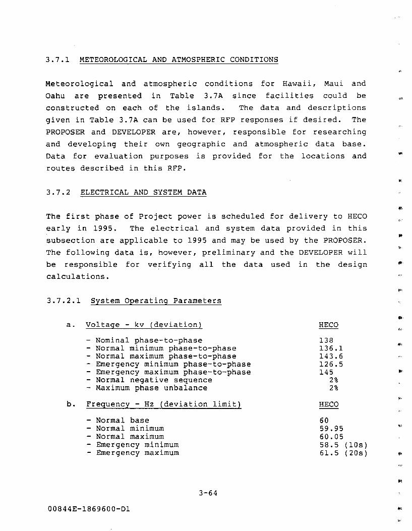
3.7.1 METEOROLOGICAL AND ATMOSPHERIC CONDITIONS
Meteorological and atmospheric conditions
Oahu are presented in Table 3.7A since
for Hawaii,
facilities
Maui and
could be
constructed on each of the islands. The data and descriptions
given in Table 3.7A can be used for RFP responses if desired. The
PROPOSER and DEVELOPER are, however, responsible for researching
and developing their own geographic and atmospheric data base.
Data for evaluation purposes is provided for the locations and
routes described in this RFP.
3.7.2 ELECTRICAL AND SYSTEM DATA
The first phase of Project power is scheduled for delivery to HECO
early in 1995. The electrical and system data provided in this
subsection are applicable to 1995 and may be used by the PROPOSER.
The following data is, however, preliminary and the DEVELOPER will
be responsible for verifying all the data used in the design
calculations.
3.7.2.1 System Operating Parameters
a. Voltage - kv (deviation)
- Nominal phase-to-phase - Normal minimum phase-to-phase - Normal maximum phase-to-phase - Emergency minimum phase-to-phase - Emergency maximum phase-to-phase - Normal negative sequence - Maximum phase unbalance
b. Frequency - Hz (deviation limit)
- Normal base - Normal minimum - Normal maximum - Emergency minimum - Emergency maximum
3-64
00844E-1869600-Dl
HECO
138 136.1 143.6 126.5 145
2% 2%
HECO
60 59.95 60.05 58.5 (lOs) 61.5 (20s)
IIi'
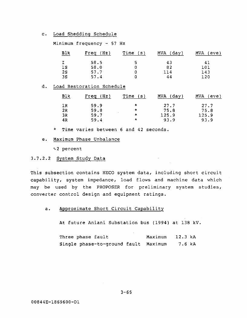
c. Load Shedding Schedule
Minimum frequency - 57 Hz
Blk Freg (Hz) Time ( s ) MVA (day) MVA (eve)
I 58.5 5 43 41 lS 58.0 0 82 101 2S 57.7 0 114 143 3S 57.4 0 44 120
d. Load Restoration Schedule
Blk Freg (Hz~ Time ( s ) MVA (day) MVA (eve)
lR 59.9 * 27.7 27.7 2R 59.8 * 75.8 75.8 3R 59.7 * 125.9 125.9 4R 59.4 * 93.9 93.9
* Time varies between 6 and 42 seconds.
e. Maximum Phase Unbalance
"-2 percent
3.7.2.2 System Study Data
This subsection contains HECO system data, including short circuit
capability, system impedance, load flows and machine data which
may be used by the PROPOSER for preliminary system studies,
converter control design and equipment ratings.
a. Approximate Short Circuit Capability
At future Aniani Substation bus (1994) at 138 kV.
Three phase fault Maximum
Single phase-to-ground fault Maximum
3-65
00844E-1869600-Dl
12.3 kA
7.6 kA
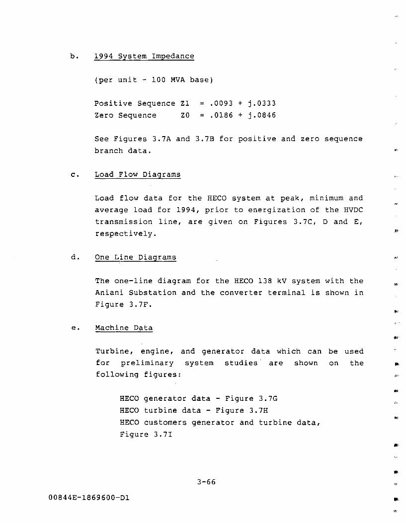
b. 1994 System Impedance
(per unit - 100 MVA base)
Positive Sequence Zl = .0093 + j.0333
Zero Sequence ZO = .0186 + j.0846
See Figures 3.7A and 3.7B for positive and zero sequence
branch data.
c. Load Flow Diagrams
d.
Load flow data for the HECO system at peak, minimum and
average load for 1994, prior to energization of the HVDC
transmission line, are given on Figures 3.7C, D and E,
respectively.
One Line Diagrams
The one-line diagram for the HECO 138 kV system with the
Aniani Substation and the converter terminal is shown in
Figure 3.7F.
e. Machine Data
Turbine, engine,
for preliminary
following figures:
and generator data which can be used
system studies are shown on the
HECO generator data - Figure 3.7G
HECO turbine data- Figure 3.7H
HECO customers generator and turbine data,
Figure 3.7I
3-66
00844E-1869600-Dl
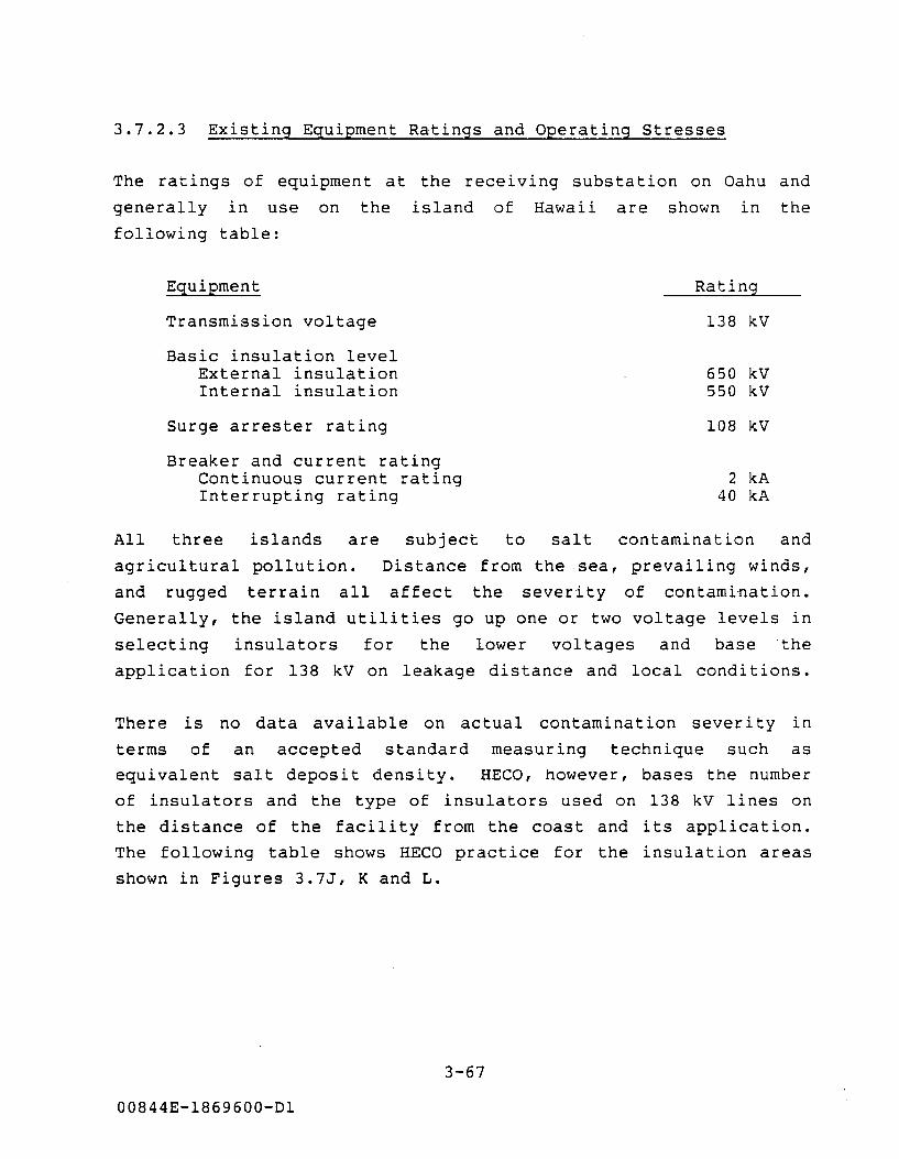
3.7.2.3 Existing Equipment Ratings and Operating Stresses
The ratings of equipment at the receiving substation on Oahu and
generally in use on the island of Hawaii are shown in the
following table:
Equipment
Transmission voltage
Basic insulation level External insulation Internal insulation
Surge arrester rating
Breaker and current rating Continuous current rating Interrupting rating
Rating
138 kV
650 kV 550 kV
108 kV
2 kA 40 kA
All three islands are subject to salt contamination and
agricultural pollution.
and rugged terrain all
Distance from the sea, prevailing winds,
affect the severity of contamination.
Generally, the island utilities go up one or two voltage levels in
selecting insulators for the lower voltages and base the
application for 138 kV on leakage distance and local conditions.
There is no data available on actual contamination severity in
terms of an accepted standard measuring technique such as
equivalent salt deposit density. HECO, however, bases the number
of insulators and the type of insulators used on 138 kV lines on
the distance of the facility from the coast and its application.
The following table shows HECO practice for the insulation areas
shown in Figures 3.7J, K and L.
3-67
00844E-1869600-Dl
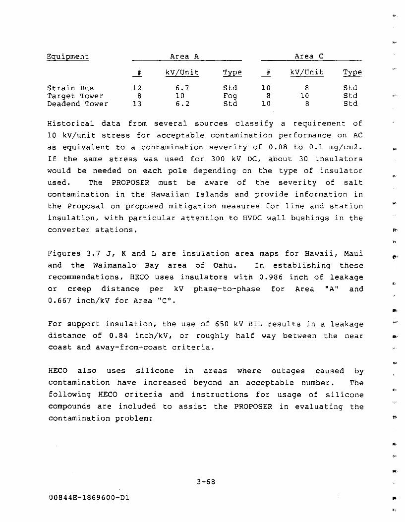
Equipment
Strain Bus Target Tower Deadend Tower
#
12 8
13
Area A
kV/Unit ~
6.7 Std 10 Fog 6.2 Std
Area C
# kV/Unit ~
10 8 Std 8 10 Std
10 8 Std
Historical data from several sources classify a requirement of
10 kV/unit stress for acceptable contamination performance on AC
as equivalent to a contamination severity of 0.08 to 0.1 mg/cm2.
If the same stress was used for 300 kV DC, about 30 insulators
would be needed on each pole depending· on the type of insulator
used. The PROPOSER must be aware of the severity of salt
contamination in the Hawaiian Islands and provide information in
the Proposal on proposed mitigation measures for line and station
insulation, with particular attention to HVDC wall bushings in the
converter stations.
Figures 3.7 J, K and L are insulation area maps for Hawaii, Maui
and the Waimanalo Bay area of Oahu. In establishing these
recommendations, HECO uses insulators with 0.986 inch of leakage
or creep distance per kV phase-to-phase for Area "A" and
0.667 inch/kV for Area "C".
For support insulation, the use of 650 kV BIL results in a leakage
distance of 0. 84 inch/kV, or roughly half way between the near
coast and away-from-coast criteria.
HECO also uses silicone in areas where outages caused by
contamination have increased beyond an acceptable number. The
following HECO criteria and instructions for usage of silicone
compounds are included to assist the PROPOSER in evaluating the
contamination problem:
3-68
00844E-1869600-Dl
'*""-
• Silicone compound is applied by hand, preferably, or brush if
necessary in such a manner that the coating has a minimum
thickness of 1/16 inch.
• Due to the relatively short length of time this silicone
compound coating has been in use, there is no reliable
information on the length of time for which it is effective.
This is determined from field experience at each location.
• The following procedures for determining replacement and/or
frequency necessary for replacement of silicone compound are
used:
a. Record all initial installations of compound as to date,
location and circuit voltage.
b. Make periodic inspections for indications of flashover
or arcing of insulators coated with compound.
c. Do not replace compound merely because it appears dirty;
an inherent property of this coating is that it traps
and insulates contaminants.
d. Replace compound only when a visual examination shows
definite evidence of arcing to insulator base or pin, or
flashover across the insulator or bushing.
e. Replace compound only on insulators or bushings in the
immediate area, or if an overhead line, on structures
immediately adjacent to failure.
f. In case of flashover, determine exactly where flashover
occurred and record location and circuit voltage.
3-69
00844E-1869600-Dl
g. Record all replacements of compound as to date, location
and circuit voltage.
3.8 INTERCONNECTION REQUIREMENTS AT RECEIVING SUBSTATION
The location for the inverter on Oahu is not fixed and is the
responsibility of the DEVELOPER. However, the receiving
substation has been tentatively located at an undeveloped site
called Aniani. This 3. 6 acre site is about three miles inland ""
from the shoreline along Waimanalo Bay. Depending on the exact
location of the cable landing and the site of the converter
station, the 138 kV lines to Ani ani Substation could be 1/4 to
three miles long. It is possible that the 300 kV HVDC cable could
be brought ashore and taken inland underground to a converter
station near Aniani Substation.
interconnection would be very short .
In this case the 138 kV
. A preliminary sketch of the Aniani Substation is shown in Figure •
3.8A. Revenue metering for the power received by HECO will be at
Aniani Substation and the DEVELOPER will be responsible for the
interconnecting AC lines.
HECO' s requirements for the Waimanalo converter terminal are as
follows:
• The AC voltage at the Waimanalo converter terminal shall
be 138 kV when the converter terminal is operating as
the lowest voltage inverter in the bipolar mode.
• The nominal power rating of the Waimanalo conveter
terminal shall be 500 MW when the converter terminal is
operating as an inverter in the bipolar mode.
• To account for contingencies, the continuous overload
rating of the Waimanalo converter terminal shall be
3-70
00844E-1869600-Dl
375 MW when the converter terminal is operating as an
inverter in the monopolar mode.
3. 9 SYSTEM OPERATION, MONITORING COMMUNICATION AND MAINTENANCE
The integration of a HVDC link into an AC system, even as a link
between two strong systems (high short circuit ratios) or between
a large generation source and a strong system, must be very
carefully studied and analyzed. This Project adds a measure of
complication to that process in that the degree of cycling
capability in the geothermal generation source is unknown, and
thus the amount of control of the HVDC power level and AC voltage
is also unknown. The HECO AC system is also relatively small in
comparison to the complete Project HVDC MW capacity (equivalent
short circuit ratio is six at peak load and about 2.5 at minimum
load), which reduces the controllability of the HVDC system during
AC fault conditions. The HVDC system by itself is normally very
flexible and highly controllable in that control of power
magnitude, VAR consumption (voltage}, frequency and power
modulation can all be built into the HVDC control. Furthermore,
the DC system can be monitored and operated remotely at either the
bipole or pole level. The PROPOSER should clearly identify the
amount and phasing of electric generation that is proposed and
clearly identify how this is related to the overall Project
control scheme.
3.9.1 OVERALL SYSTEM INTEGRATION AND TELECONTROL
Block diagrams and an explanation for the integration strategy for
coordination of the geothermal resource electric generation, the
HVDC transmission, and HECO dispatching and load requirements
should be included in the Proposal. Complete control diagrams for
the HVDC system should be shown in the responses to Section 3.6.8,
along with other details of the converter terminal control
functions.
3-71
00844E-1869600-Dl
The Proposal should describe how and to what degree it is intended
to vary the output of the geothermal generation to meet the HECO
daily load variations as described in Section 5. The PROPOSER
should assume that HECO will regard the Project as a base load
source, with control of the Project output the responsibility of
the DEVELOPER. HECO will transmit verbal orders for power changes
as dictated by HECO system requirements. The DEVELOPER will
operate and dispatch the geothermal units. If the PROPOSER
includes a geothermal well, energy gathering system, and power
production facility design which allows significant cycling, the
HVDC and generation control scheme should include a tie to HECO's
control center in Honolulu which permits HECO to dispatch that
cycling power to the extent allowable.
3.9.2 COMMUNICATION AND TELECONTROL
HECO, MECO, and Hawaii Electric Light Company (HELCO) each own and
operate an island-wide communications network, within their own
service territory, consisting of private-carrier microwave, mobile
radio, and land lines. HECO has an active fiber optic network;
HELCO is in the process of installing a fiber optic system. A
HECO Inter-Island Communications System (ICS) is proposed to be in
operation by the end of 1989, and will provide voice and data
communication channels via microwave interconnecting all three
island utili ties. The HELCO terminus for the ICS will be near
Huehue Ranch in the North Kona district, and the MECO terminus at
Kahului. Communications coverage of the Puna district is via
mobile radio only at this time. A microwave link between HELCO's
Kanoelehua Power Plant in Hilo to the Ormat geothermal plant in
Puna is scheduled to be operational by the end of 1990. All the
utilities also lease telephone circuits for special applications
and backup.
HECO and HELCO may provide channels on the ICS and the analog
microwave system, respectively, to the DEVELOPER for communica-
3-72
00844E-1869600-Dl
lllil'
tions, telemetering and control needs if they are used to provide
HECO load requirement information to and from the HVDC system,
provided that 1) the DEVELOPER'S telecontrol scheme is compatible
with the HECO and HELCO systems, 2) sufficient channels are
available on the ICS and HELCO' s analog microwave system and
3) the DEVELOPER provides the interface between the ICS and
DEVELOPER'S control center, all at DEVELOPER'S cost. The
DEVELOPER must still supply an independent communication and
telecontrol scheme as described in Section 3. 6. 9 for control of
the HVDC system. The Proposal should describe in detail any
proposed use of the HECO, MECO and HELCO communications
facilities.
3.9.3 MONITORING AND REVENUE METERING
Since the DEVELOPER will operate and dispatch the geothermal
electric production facilities and control the HVDC transmission
system, provision for monitoring of the DEVELOPER'S power, voltage
and current measurements by HECO is not mandatory. For purposes
of evaluation, the PROPOSER should include a block diagram and
description of the internal monitoring and telecontrol system
between the HVDC system, the AC collection system and the electric
power production facilities.
Revenue metering of the power purchased by HECO will be
accomplished at the point of interconnection at HECO' s Aniani
Substation, shown on Figure 3.6E. For billing purposes, electric
energy output of the DEVELOPER'S facilities at the point of
interconnection shall be measured in KW and KWH on a time of use
basis. Reactive power flow will be measured in KVAR and KVARH.
Metering equipment shall be of two percent (2%) accuracy and
calibrated and tested periodically according to HECO standards.
3-73
00844E-1869600-Dl
3.9.4 MAINTENANCE PRACTICES AND ORGANIZATION
The DEVELOPER, will be responsible for the operating practices,
maintenance organization and procedures adopted to operate and
maintain the system in order to obtain the reliability and
availability standards set forth in the PPA. The PROPOSER should
follow recognized standards, rules, and guidelines for design,
construction, and rating of all electrical and mechanical
equipment. Furthermore, it is expected that the operating and
maintenance practices adopted will closely follow those in common
use by HECO for their facilities. For evaluation purposes, the
PROPOSER is requested to provide a detailed description of the
proposed operating organization with a complete Organization Table
as it is perceived at the time of response to this RFP.
3.10 BIBLIOGRAPHY
The following Bibliography is taken from the Hawaii Deep Water ""'
Cable Program, Phase II-D, Task 5, Section 2.
3-74
00844E-1869600-Dl
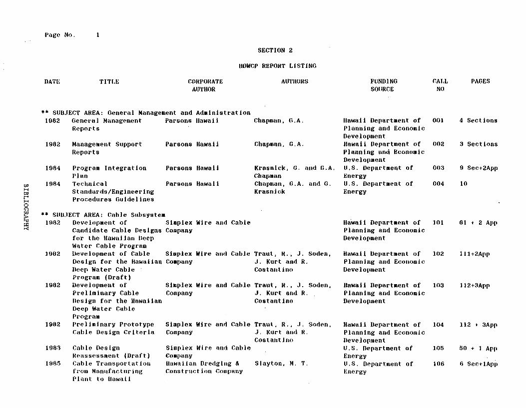
Page No. 1
DATE TITLE COIU'OHATE AUTHOR
SECTION 2
IIOWCP REPORT LISTING
AliTIIOHS
** SUBJECT AREA: General Management and Administration 1982 General Management Parsons Hawaii Chapman, G.A.
1982
1984
1984
l~eports
Management Support lteports
Program Integration Plan Technical Standards/Engineering Procedures Guidelines
Parsons Hawaii
Parsons Hawaii
Parsons Hawaii
Chapman, G.A.
Krasnick, G. and G.A. Chapman Chapman, G.A. and G. Krasni(:k
** SliUJECT AREA: Cable Subsystem 1982 Development of Simplex Wire and Cable
Candidate Cable Designs Company for the Uawaiian Uecp Water Cable Program
1902 Development of Cable Simplex Wire and Cable Traut, H., J. Soden, Design for the Hawaiian Company J. Kurt and R. Ueep Water Cable Costantino Program (Draft)
1982 Development of Simplex Wire and Cable Traut, R., J. Soden, Preliminary Cable Company J. Kurt and R. Uesign for the Hawaiian Costantino Deep Water Cable Program
1982 Preliminary Prototype Simplex Wire and Cable Traut, R., J. Soden,
1983
1985
Cable Design Criteria Company J. Kurt and R.
Cable Design He~ssessment (Draft) Cable Transportation from Man11facturine Plant to llawati
Simplex Wire and Cable Company Hawaiian Dredging & Construction Company
Costantino
Slayton, M. T.
II await
FLINDINB SOURCE
Department of Planning and Economic Development Hawaii Department of Planning and Economic Development u.s. Department of Energy u.s. Department of Energy
CALL NO
001
002
003
004
lla·wai 1 Department of 101 Planning and Economic Development
llawaii Department of 102 Planning and Economic Development
llawaii Department of 103 Planning and Economic Development
Hawaii Department of 104 Planning and Economic Development li.S. Department of 105 Energy U.S. Department of 106 Energy
PAGES
4 Sections
3 Sections
9 Sec+2App
10
61 + 2 App
111+2App
112+3App
112 + 3App
50 + 1 App
6 Sec+1App
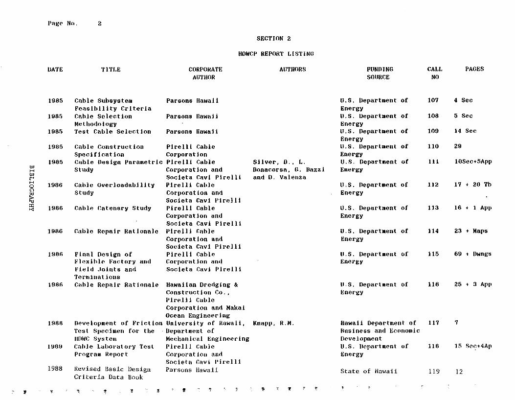
Pnge No. 2
SECTION 2
HOWCP REPORT LISTING
DATE TITLE CORPORATE AUTHORS FUNDING CAJ,L PAGES AUTHOR SOURCE NO
1985 Cable Subsystem Parsons !lawai i u.s. Uepartment of 107 4 Sec Feasibility Criteria Energy
1965 Cable Selection Parsons llawaii u.s. Department of 108 5 Sec Methodology Energy
198f) Test Cable Selection Parsons llawaii u.s. Department of 109 14 Sec Energy
1985 Cable Construction Pi relli Cable u.s. Department of 110 29 SpecHt cat ion Corporation Energy
1985 Cable Design Parametric Pi relll Cable Silver, 0 .. L. u.s. Department of 111 10Sec+5App tD study Corporation and Donacorsn, G. Dazzi Energy H tD Societa Cavi Pirelli and 0. Valenza t"' H 1906 Cable Over 1 oadabi 11 ty Pirelli Cahlc u.s. Uepartment of 112 17 20 Tb 0 + C) Study Corporation and Energy ~ Societa Cavi Pirelli ~ 1986 Cable Catenary Study Pirelli Cable u.s. Department of 113 16 + 1 App
Corporation and Energy Societa Cavi Pirelli
1906 Cable Repair Rationale Pirell i Cable u.s. Department of 114 23 + Maps Corporation and Energy Societa Cavi Pi rclli
1986 Final Design of Pirelli Cable u.s. Department of 115 69 + Dwngs Flexihlc Io'aetory and Cm·porat ion and Energy Field ,Joints and Societa Cavi Pirelli Terminations
1986 Cuble Repair Rationale Hawaiian Dredging & u.s. Department of 116 25 + 3 App Construction Co .. Energy Pirell 1 Cublo Corporation and Makai Ocean Engineering
1988 Development of Fr lctlon University of Hawaii, Knapp, R.M. llawaii Department of 117 7 Test Specimen for the · Department of Business and Economic IIDWC Syste111 Mechanical Engineering Development
1989 CahJe Laboratory Test PirelJ i Cable u.s. Llepartment of 118 15 Set.;-t4Ap Program Report Corporation and Energy
Societa Ccwi l'irell.i 1988 Revised Basic Design Parsons Hawaii State of Hawaii 119 12
Criteria Data Book
' 1 f " , !: tf ' :t
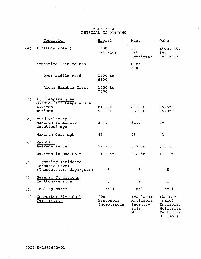
TABLE 3. 7A PHYSICAL CONDITIONS
Condition
(a) Altitude (feet)
tentative line routes
Over saddle road
Along Hamakua Coast
(b) Air Temperatures Outdoor air temperature maximum minimum
{c) Wind Velocity Maximum (1 minute duration) mph
Maximum Gust mph
(d) Rainfall Average Annual
Maximum in One Hour
(e) Lightning Incidence Keraunic Level (Thunderstorm days/year)
(f) Seismic Conditions Earthquake Zone
(g) Cooling Water
(h) Converter Site Soil Description
00844E-1869600-Dl
Hawaii
1100 (at Puna)
1100 to 6500
1000 to 2000
81.3°F 55.0°F
34.9
45
22 in
1.8 in
8
3
Well
(Puna) Histosols Inceptisols
Maui
30 (at Maalaea)
0 to 3000
83.1°F 55.0°F
32.9
45
3.7 in
0.6 in
8
2
Well
(Maalaea) Mollisols Incepti-sols, Misc.
Oahu
about 100 (at Aniani)
85.6°F 55.0°F
29
41
3.6 in
1.3 in
8
1
Well
(Waima-nalo)
Entisols, Mollisols Vertisols Ultisols
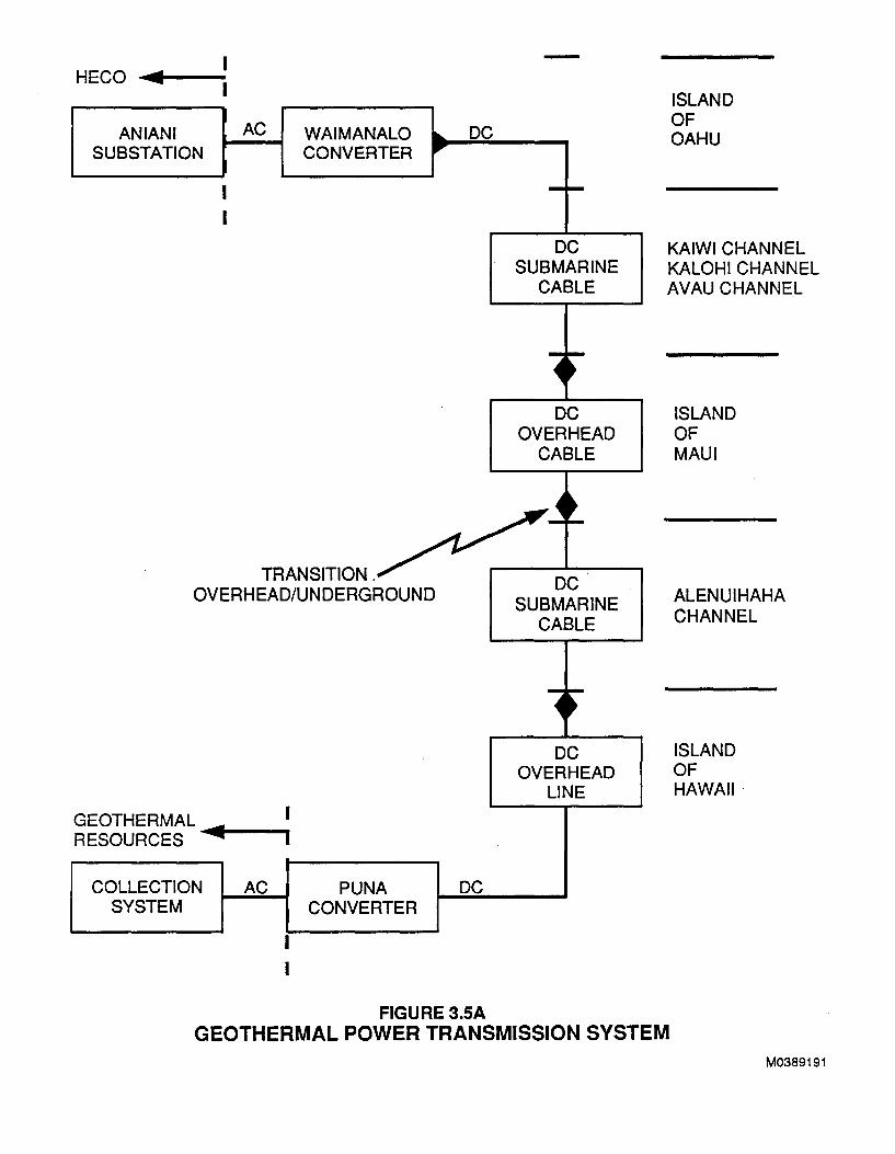
HECO ...,..,... __ _
AN IAN I SUBSTATION
AC WAIMANALO CONVERTER
TRANSITION . OVERHEAD/UNDERGROUND
GEOTHERMAL .... RESOURCES ~-~
COLLECTION SYSTEM
AC PUNA CONVERTER
DC
DC
FIGURE 3.5A
DC SUBMARINE
CABLE
DC OVERHEAD
CABLE
DC SUBMARINE
CABLE
DC OVERHEAD
LINE
ISLAND OF OAHU
KAIWI CHANNEL KALOHI CHANNEL AVAU CHANNEL
ISLAND OF MAUl
ALENUIHAHA CHANNEL
ISLAND OF HAWAII·
GEOTHERMAL POWER TRANSMISSION SYSTEM M0389191
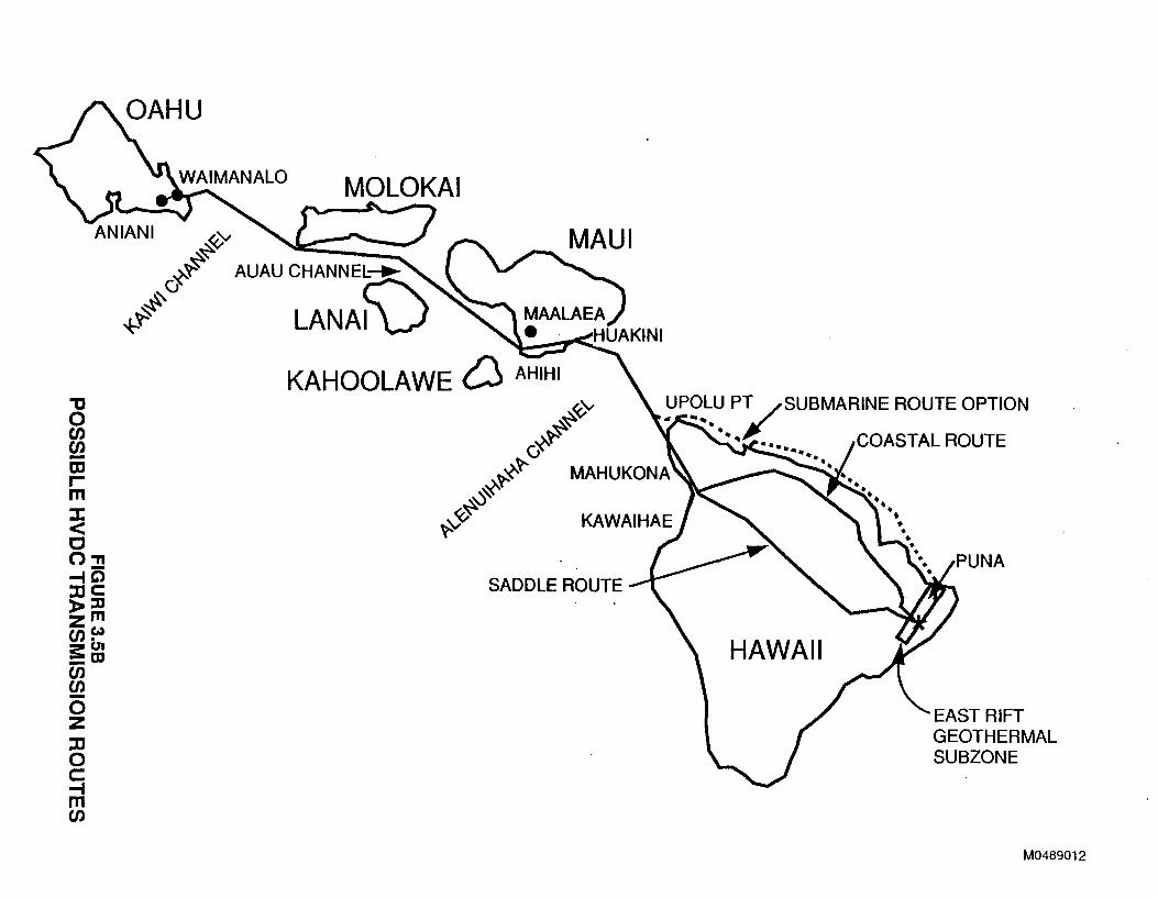
"'0 0 en en -Dl r m ::r: < c o, -IQ :DC )>:0 zm en~ !5:01 _m en ~ 0 z :D 0 c -1 m en
~ ~ Y:-.t AUAU CHANNEl:f\)~
~CJ
+~~ LANAI
KAHOOLAWE D AHIHI
fv'v ~~
~~ (j
~-<-~ MAHUKONA ~~
<v~ ~
SADDLE ROUTE
HAWAII
EAST RIFT GEOTHERMAL SUBZONE
M0489012
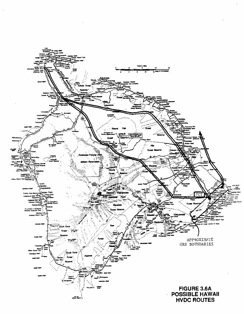
--
---- ...... ------ ----
.. .. 10 11 ScBin KiiOIIIIIIIl
FIGURE 3.6A POSSIBLE HAWAII
HVDC ROUTES
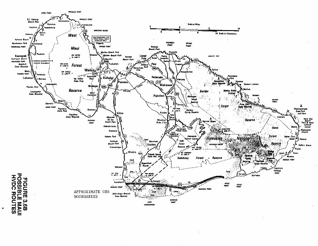
•
Honot.ow11 Part.
HCWO«lM'A I'OiNT
Kaanapali K.4imapalt Beach .......UOOI'GIIfT
Wohiiuh Sttrt Warsidt
"'0 ::1:0'11 <cnCcnG> 0-C JJOJ::D 0 rm cmw -tS::m ml>m cnc -
IJI'GI roiNT N.WUii POINT
---(--
I
/I / I I I
' I r-'
I I
HEW POINT
I'WitU«IM EL VII fl
Maui WC.UIU
A 4 tWft
WJ NffQtf £L U50 Fl •
Reserve
APPROXIMATE GRS BOUNDARIES
li
CAP£ HAAI4AIANUIA
I
PAUWBA /'OINT
IAN.UM POINT
0
0
Scllo in Milos
li 10
I 10 Selle in Kilometen
DPANA I'IJINT
......,AM I'CIIIIf
I ·~I Fpr••'
Forest . •. . ,-, " ...... \ \ --\ "" ,_ .... -
----
' ·'
,\r
ICAIL/0 POINT
ICAIAHU I'OINT
A
H•n• Str s .. ch Ptrk a H1n1
Cultur~l Cen111
Wantnalut Church
Hamo•
Gr1111
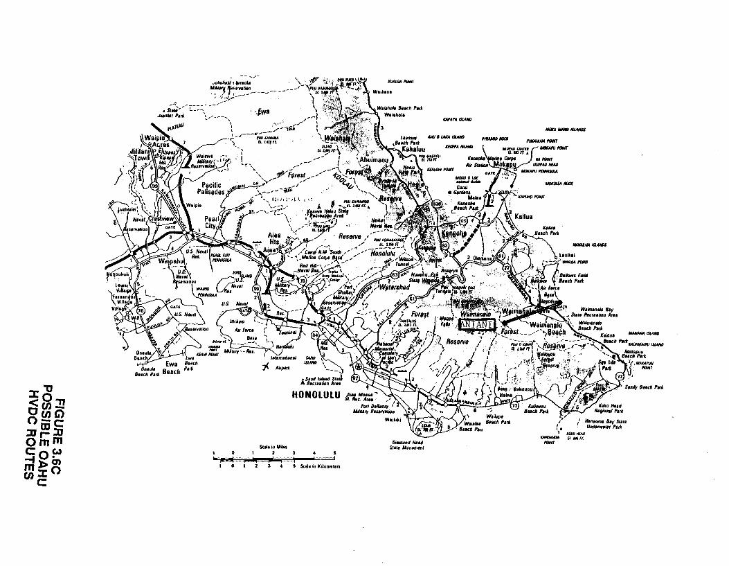
0
FIGU
RE
3.6C
PO
SS
IBLE
OA
HU
H
VO
C R
OU
TES
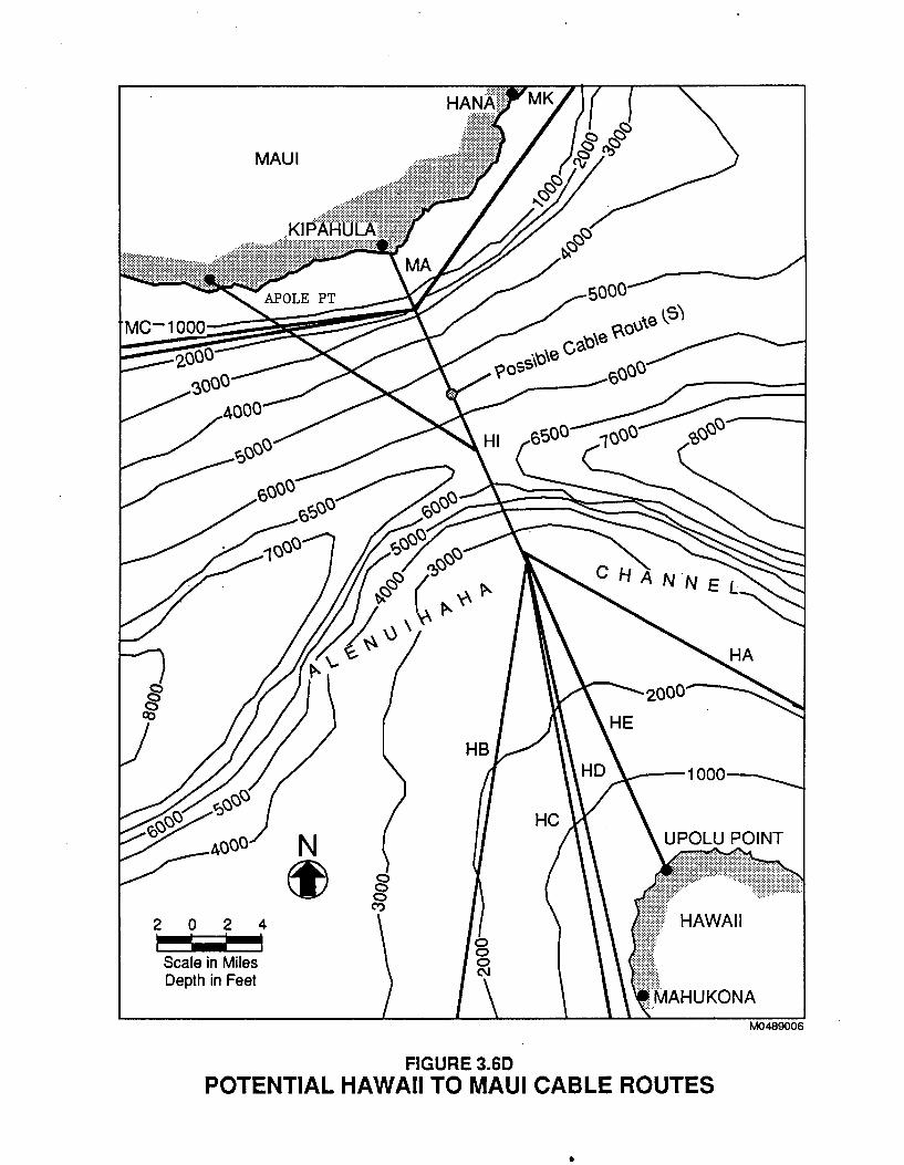
MAUl
2 0 2 4
Scale in Miles Depth in Feet
N ~
FIGURE 3.60 POTENTIAL HAWAII TO MAUl CABLE ROUTES
•
1\,10489006
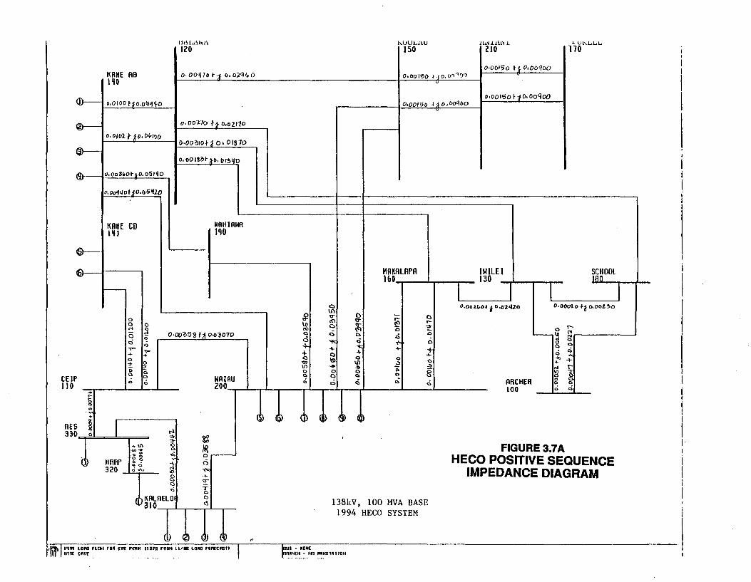
CEJP 110 . ...
g -~ ...
RES ~ 330 6
l
lli\Li>hf\ IZO
1-_;___:__,~___;:::._-1 0 ·00 ~I 0 t 1 0 I 0 IS 10
O, 00 ~~~~ A-D• 0 13'10
r
HRRP 320
0 () 0 .... :l 0 0 ci 0 .,- ;-.... ... 0
~ "* 0 0 0
.; 0
0
-...ltl ..... ~~ o':' oo .;.....,
t-1 ~ -:)-0 0
~ ;t "' c C> () .;
t:
WAHIAWA Jqo
~r-6
"""' .... ~ T 0
t)KALAELO c 310 ~
() (~ (~ (~ ,'E'J) Tt-t'ft LDf'D n~ raA rn PmK Uina rnDH lVIII Lola FOA£CR!ifl I '1fJ I IAiE (A!iE
. - ...... .
1\.UULi\U 150
J\1~111.1~1
ZIO L Ui\.C.LC. no
v
I WILE I ·...,...-...L-,r----r- 130
I ~~~DOL
I
138kV, 100 MVA BASE 1994 HECO SYSTEM
o.oou.o1 t o,oz-Jlo
ARCHER 100
o. ooCll o 1-~ o.ooZ.!>o
FIGURE3.7A HECO POSITIVE SEQUENCE
IMPEDANCE DIAGRAM
I
I I I
i
I I
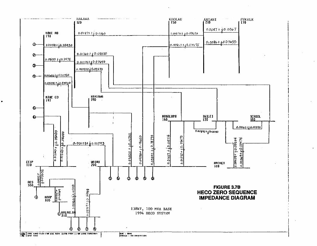
•
®--
KRHE AB 1~0
a. 0553 J-10.1'11~ ®---- 11
o.o5130 1-.io:z:~o;z.o u '
KRHE CO 1~1
0 0 ~ 0
c) -+
~ C) cS
()
g ID ()
~ .....,. + 0 3" r-1 0 lci
HALAWA 120
o. 011110 t :l o. 0&010
o.oJTJOH0.07G.qo u
o. OID'IOt.i0.05l.10 .
IIRHIAWA Jqo
WAIRU
KOOLAU ISO
AN IAN I 210
o.oon f- fO.o3itJ7
.PUKELE 170
CEIP J 10 . 200~~~~~--~~r-~--~----~----~--------
I 0 T
+a- ... <$> ....... <> :r. ....... ti ~.--HRRP
oe!; ·-~= g.;
6 320 <S""' .., IS)
'~ ,. ... 0 0 t-0 <>
t-
<)KALAELO "' 0
310 c
,H\ )t~:~ft LORD rLDf raR rn: PEAt( (llll rnaH l I/IB LORD FOAEtrGrt I (l!r ' I A 'F. [AS£
138kV, 100 MVA BASE 1994 HECO SYSTEM
laUS - NONE f.'AA~CH - tn ruma nn mu
FIGURE3.7B HECO ZERO SEQUENCE IMPEDANCE DIAGRAM
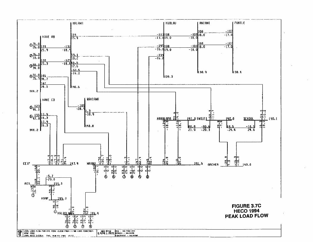
r------- -------- -~ ·----- -- ·--·----·--------·· -· -·----- --·----- --------~-----·-- ----·- ------·-------------------------·· ---------
tlRLRHR
11'1 15.1!
~~21~53'1~_0 ________ -1~3~'• ., -18. (
~ 130
~2S.3 314.0
i1h-llt. o Ito& "'35. '} 3~. 7
1102 20.3
11411.2
KAHE CO
~ 114 .I
-12' 10.2 -18 b. fl
• 12.1J -53.5 11!.2
1'10.&
-1 0~
WRHIAWA
.r.l'l&!llC! ~16.3
-28.< 1.3 ~-~18~.~q-----~
1141!. 2
~ H.3
0'1
HO.B
(\J IJ'C\J .. . ~
-or- ~ ~ ~~~ CEir -- 1'13. q I I I 1--<ITl HAIRIJ I !!;-~0
:;j-; ~-IN 1111
I -5.7
I
AES ~~ 1-20.0 144.3
11)0) ul~ :r
7~ -.o
dr HARP 1'14.3
o-
CPCXI It)- 0 O:J
()KRLREI_~i ~~ 1qqq C":C:i'O!'JCO
1 0 '0 fill' ,.;1';::N l!:ru o-.- ~-( D G~ (D ~D
tl lCJ'N LORD Flr:.t fDA UE PDU< U22B F""ROH 11/IB tOAD FD~CRSrl lASE CA5£ l~'J't HHD S'fST£H FU~ FEB OJ 1'11'1 I'I:Sl
..... 0
"'-: ~ . ~ ~ 0 011) ~N ~~ ITl -- -<I'-I I I 1- ~N
00 00 00 00 c 0 00
00 ~~ :!Jln -ui c 0 00 N DN
C> ~~ 0 Q} (~ ~~
KOOLRU
-II 108 -13. llll. 0
-PI~ lOB -lb. lt '3. 0
-lljll
-lb.2
139.3
.co
HRKAI APA ~ ~ ':tOO .cr-
C\. • - • - OCI ~CD I ....t I .....t
I I
CD 0
~~ ~0 -N
ANI ANI rUK[lE
I lOB -I 01 -toe t8.o -17.0
-18.C
108 -107 -10 18.0
-18.0 -17.0
136. Q 138 .•
::rr-- ON
~- Cl'.; 141 0 IIHLEI ~ I' lifO 0 SIIW.WCHO~Olr--:=Ull~l'-1 qo,l I ~J .o.....;:,a:=-UI +-""'-' I CflO
lao.A -AO. ~~ II.S -IR.SI ~~ 21. g -20. 3 ~-2~ • ....,_ .. ::-------±2!!-Aq _-¥.~ ..
Jlll b ARCHER
-
OCI CYlO
~~ Ollll N • If- I I 1140.0
FIGURE 3.7C HECO 1994
PEAK LOAD FLOW

•
r-~-------·---- ---··---- ---------···--- -- ~- .. ~------------------ ··- ·----------------~---------------------------- --- ----------·------
KAIIE AIJ
~'!5.'1 -~5. P_-"-'0.'-:'3----'-'-1<-'-."JJ f
~ H.2
@~ -0.3 2. 7
.fl\_35. 0 .,~ 'l "' 2. 7 O.b
:'1} 7 -1.7
IIJ 3. I
KRHE CO
IIALRHA
30.5 -£>.7
'l.4
1'12. 'l
-3'1
MAHIAWA
~ o.s -0.1 0. I F_~q~.~~------,
It\ (1, 0 -· .S 10" 0. 0 -2.2
# -2.2 1~2.&
11.!3.1
a .0 ~ err-- Cll.O ~N
HAIRU ~ NN ;1 ..
0 !II • 1ni Ill-I IN I
lfNIO rue N
cnr :tru; ru~ - l '13.] 0
~~ I
-3.1 :l:t' Jo·\111 a AES ~.._:
t u u: r.: ..0
I I
HARP 1'13.3 o-
''
lliiJfi LDRO FLrn ron "lN LmO tlfllll FRO" 11/81 LORD FDREtASTI lASE [R5E JIJ9t HErD SlSTEtl FRJ .. FEB 03 l'IICJ lit: Sl
..ro 00 c 0 00" OlD C:: 0 c 0
~~ 00 c 0 ~- ION C: (T1 rl iii ....
0 co I
~~ a~ (D ~~ (~ @
UW. l'l'ltD l t:5 -'fDllAii£ IK¥1 ~ L~..!l RANCH - ~/HVHA
QUtPHftn - tiMIRVRA
KOOLAU
-30.1J3b.6 S.IJ -0.7
-'16.13&. 6 O.IJ-0. 7
-ll5. 0.
lll2.1J
HAKAI APR d;(Tl
~":' I
..£;\()
g:D'
CID
~.,; ,. ~f I
1\0
LP
ANI ANI
3b .a -36.E-0.7
0. E
3b. B -36. o. 7
O.E
Jll2 ...
a :1
142 .. 5 JHILEI ~
bq, I -2'1 •. J 7.Q -7.1
"' 1/)
I
rUK[LE
-3.6_
-3&.7 0.<)
1.!2.3
a"' - . 142 2 Sr.HOOI ~"? lq2.2
u-
-5, ljl 0 Ul
a.; •• " lT) ... .....
I -21.3 2 •. 3
'---
Ul
u: ... a • (T)
IDO 11J2 8 ARCHER ..... 'fj' 1'!2.2
FIGURE 3.70 HECO 1994
MINIMUM LOAD FLOW
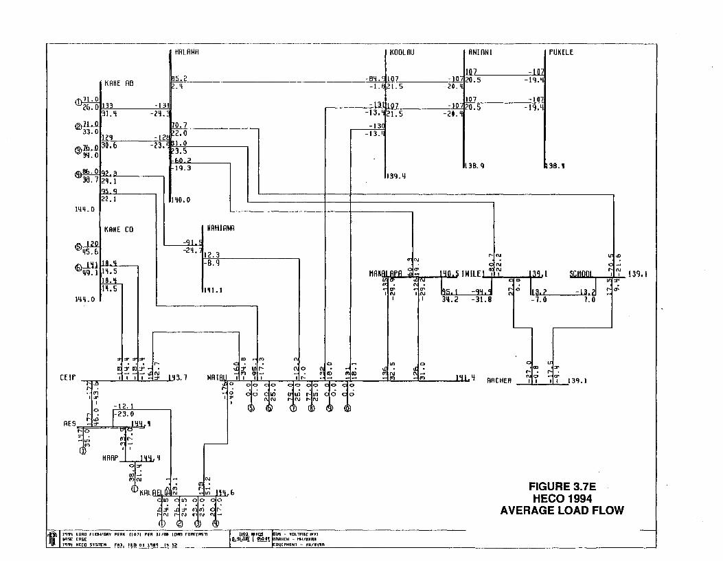
r------·-----------·----·---------·-----·--------·------------------------------------------------,
KAHE AB
'"'8&. 0 q' .3 IY36. 7 2q.1
gs_q 22 .I
Jljll. 0
KRHE CO
HAL AHA
~_5. 2
~0. 7 -12E P2, 0
- '3 I. 0 ' • ?3.5
&0 .. 2 1\1.3
1'10.0
MRHIRWA
-<JI . ~
-Z'I. l-'-1~2,_,. 3;-----------, -s,q
Jljll. 0
":t' :t' :t' II) ~co C\ ... 0 -~ . _:i: :1' Ill r- ('10 ~cO WAIAl -~ 1'1 II'- lr: ~~ I I I --!(~~ :!::;; N l 'I:!. 1 CEtr I I I 1- :I'
~~ 00 < 00 00 < 0 00 0
00 ~ If) !! IS) ,... If) (; 0 00 1:1' 1\ N t-1\1 t-N I
~!} ~~ (i) ~~ (~ ~b
~~ I :t'
I -12. I
0
E~ ,-23. 0 AES Jljlj '
ul"':
~ ~~ -
HARP 1'1'1.'1 o::r ..
''
IIIIJ'I't LORD FLBVDRY PERK uo11 PER Jl/81 lDfll rDRHR!ill lASE CASE lii:J'ft HE[O 51STEH FU. FEB 0:1 lqiCJ ltt· S2
UMU. "'leD '!:S - ~OLTAiit lUI ~ L!'-iO I\ hRN<H - Kl/HVAR
DU( PHENl - t111/N'IRR
KOOLAU
-8'1.~107 -1.821.5
-131[07 -]3. 21.5
-130 -13.4
13<1.1J
<J-:N
HAKAI APR ~ o-::: 0' ~ "! I g; ~~
I I
Ill 0
~~ ~~
AN! ANI
107 -10 20.5
-2o.q
107 -10 20.5
-20.'1
138. q
t-N
ON
-lQ
-I 07 - t<},ll
I 4 0 .. 5 I H ILE"-1-r~' u.~--:=:r.::--11~ 3 q I
lqs, 1 -qlf J ~ ~ s. ? 311.2 -31.8 -7.0
0 • al
I '11 'I ....
ARCHER ~'f
f'UK[U:
38 .•
tr::r
~a: I I 13'1.1
FIGURE 3.7E HECO 1994
AVERAGE LOAD FLOW
-
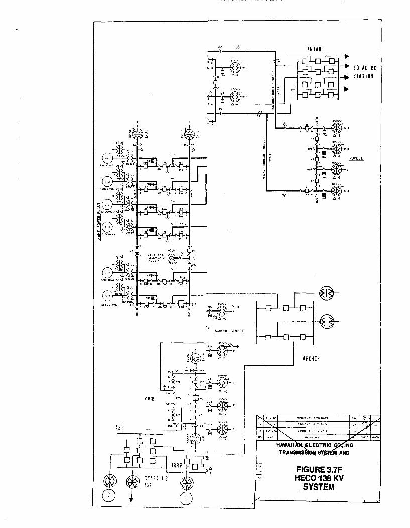
SCHOOL STREET
, . . . " . 0 • 0 ' ~ N . • •
_...._ __ ~ ~ 80000
LIOOO~~· ···2 <54 6-(
ous"c"t~• 148x 152 6-( :fe eoooo PUKELE
ous·~~~ 147~ 151 A-<
R !'A 80000
H?."!t-~· i 153 A-<
FIGURE 3 7F HECO ·138. KV
SYSTEM
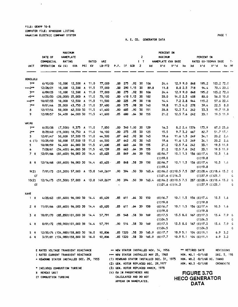
FILE: GENPP 16·8 COMPUTER FILE: XPHEGENR LISTING HAWAIIAN ELECTRIC COMPANY SYSTEM
UNIT
DATE OF MAXIMUM
NAMEPLATE COMMERCIAL RATING OPERATION KW (4) KVA
RATED WR2 PSI KV LB·FT2
H. E. CO. GENERATOR DATA
2 I T
P.F. IF SCR 2
PERCENT ON MAXIMUM
NAMEPLATE KVA BASE Xd X'd X''d Xo
PAGE 1
PERCENT ON RATED KV·100MVA BASE T-
Xd X'd X''d Xo MF
---- --- ---- -- ----HONOLULU
1** +++2**
3** +5**
++6** .,..... 8 9
WAIAU
6/10/20 10,000 12,500 A 11.0 12/28/21 10,000 12,500 A 11.5 6/09/25 10,000 12,500 A 11.0 4/20/30 (20,000) 25,000 A 11.D
10/07/33 10,000 12,500 A 11.5 9/01/44 35,000 43,750 .5 11.0
12/17/54 50,000 62,500 30 11.5 12/09/57 54,400 64,000 30 11.5
1** 6/20/38 (7,500) 9,375 A 11.0 2** 8/29/40 (15,000) 18,750 A 11.0 3 12/01/47 50,000 57,500 15 11.0 4 (1) 10/25/50 50,000 57,500 15 11.0 5 10/09/59 54,400 64,000 30 11.5 6 7/28/61 (54,400) 64,000 30 11.5 7 R 12/01/66 (81,600) 96,000 30 14.4
77,000 77,000 77,000 70,100 11,500 37,400 41,600 41,600
7,850 16,100 44,500 44,500 41,600 40,139 65,625
.80 275 .92 30 106
.80 290 1.15 30 89.8
.80 275 .92 30 106
.80 410 1.13 30 102
.80 225 .99 30 118
.80 575 .98 30 140
.80 685 .90 30 151
.85 680 .64 30 155
.80 340 1.00 30 129
.80 273 .93 30 125
.87 642 .92 30 143
.87 642 .92 30 143
.85 660 .64 30 155
.85 663 .64 30 155
.85 849 .64 30 150
8 R 12/16/68 (81,600) 96,000 30 14.4 65,625 · .85 848 .58 30 150
24.4 11.8 24.4 20.0 14.4 19.8 20.8 21.2
16.3 15.5 19.6 19.6 21.2 21.2
(E)16.7 (1)19.0 CE)16. 7 (1)19.0
12.9 9.0 848 8.8 2.5 718
12.9 9.0 848 14.0 2.5 408 7.2 2.8 944
11.3 4.0 278 12.3 7.4 242 12.5 7.6 242
195.2 94.4
195.2 80.0
115.2 39.4 33.3 33.1
8.2 2.4 1376 173.9 9.7 3.2 667 82.7
11.6 1.5 249 34.1 11.6 1.5 249 34.1 12.5 7.6 242 33.1 12.5 7.6 242 33.1 10.1 1.5 156 (E)17.4
(1)19.8 10.1 1.5 156 CE)17.4
(1)19.8
103.2 72.0 70.4 20.0
103.2 72.0 56.0 10.0 57.6 22.4 22.5 8.0 19.7 11.8 19.5 11.9
87.5 25.6 51.7 17.1 20.2 2.6 20.2 2.6 19.5 11.9 19.5 11.9 10.5 1.6
10.5 1.6
9(3) 7/01/73 (51,300) 57,000 A 13.8 149,261* .90 394 .SO 30 163.4 (E)16.2 (E)10.5 7.5 287 (E)28.4 CE)18.4 13.2 G CT (1)21.6 (1)14.3 (1)37.9 (1)25.1 G
10(2) 12/14/73 (51,300) 57,000 A 13.8 149,261* CT
.90 394 .SO 30 163.4 CE)16.2 CE)10.5 7.5 287 (E)28.4 (E)18.4 13.2 G (1)21.6 (1)14.3 (1)37.9 (1)25.1 G
KAHE 1 R 4/20/63 (81,600) 96,000 30 14.4 65,620
2 R 11/01/64 (81,600) 96,000 30 14.4 65,620
3 R 10/01/70 (85,850)101,000 30 14.4 57,791
4 R 8/01/72 (90,900)101,000 30 14.4 57,791
5 R 6 R
12/30/74 (134,980)158,800 30 16.0 3/31/81 (134,980)158,800 30 16.0
92,806 92,806
.85 611 .64 30 150
.85 611 .64 30 150
.85 548 .58 30 169
.90 514 .58 30 169
(E)16.7 (1)19.0 (E)16.7 (1)19.0 (E)17 .5 ( 1)24.5 CE)17 .5 (I )24.5
.85 1320 .58 30 165.9 (E)17.7
.85 1320 .58 30 165.9 CEJ17.7
10.1 1.5 156 (E)17.4 (1)19.8
10.1 1.5 156 (E)17.4 (1)19.8
13.5 8.0 167 (E)17.3 (I )24.3
13.5 8.0 167 (E)17.3 (I )24.3
10.9 5.1 104 CE)11.1 10.9 5.1 104 CE)11.1
10.5 1.6
10.5 1.6
13.4 7.9 G G
13.4 7.9 G G
6.9 3.2 6.9 3.2
E RATED VOLTAGE TRANSIENT REACTANCE I RATED CURRENT TRANSIENT REACTANCE
++ NEW STATOR INSTALLED NOV. 14, 1956 +++ NEW STATOR INSTALLED MAY 25, 1960
** RETIRED DATE REVISIONS HON. N0.1 ·8/1/68 DEC. 5, 198
+ REWOUND STATOR INSTALLED DEC. 29, 1955
* INCLUDES COMBUSTION TURBINE R REHEAT UNIT CT COMBUSTION TURBINE
(1) REWOUND STATOR INSTALLED DEC. 31, 1975 (2) GEN. ROTOR REPLACED DEC. 29,1977
HON. N0.2 ·8/1/68 XC. TANNO HON. N0.3 ·8/1/68 CRONKHITE
(3) GEN. ROTOR REPLACED MARCH, 1978 (4) KW IN PARENTHESES ARE
CALCULATED AND DO NOT . APPEAR ON NAMEPLATES.
FIGURE 3.7G HECO GENERATOR
DATA
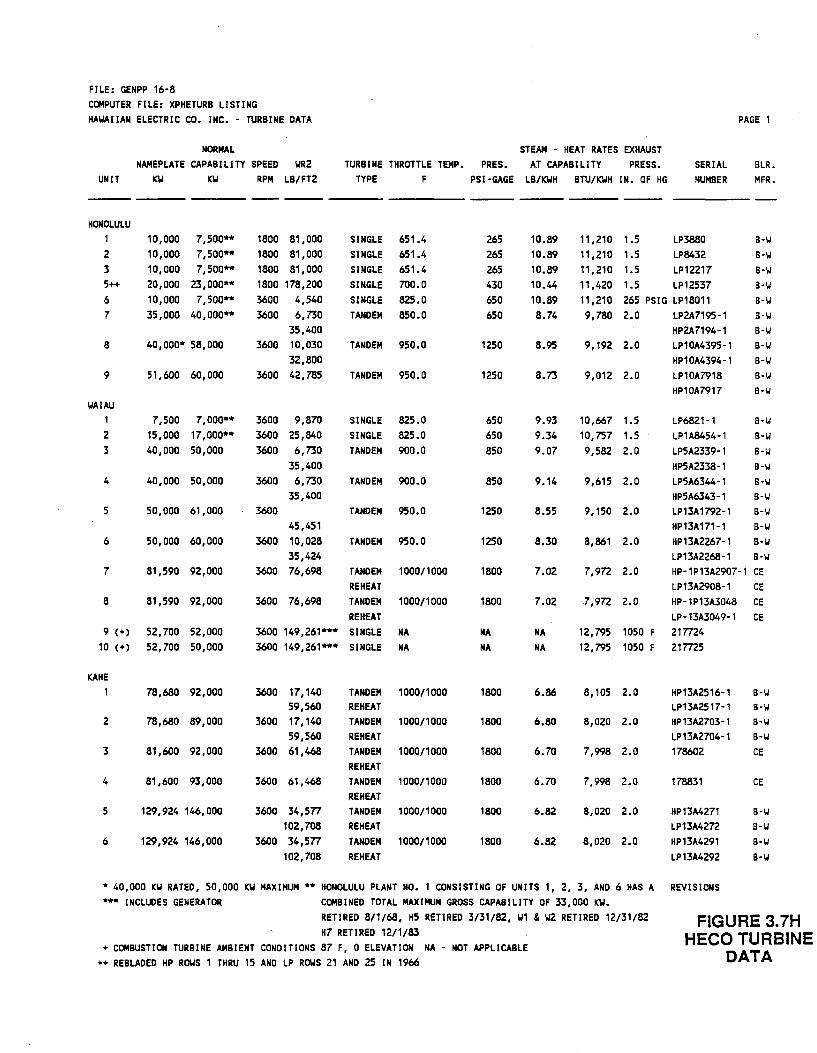
FILE: GENPP 16·8 COMPUTER FILE: XPHETURB LISTING HAWAIIAN ELECTRIC CO. INC. • TURBINE DATA
NORMAL NAMEPLATE CAPABILITY SPEED WR2
UNIT KW KW RPM LB/FT2
STEAM • HEAT RATES EXHAUST TURBINE THROTTLE TEMP. PRES. AJ CAPABILITY PRESS.
TYPE F PSI-GAGE LB/KWH BTU/KWH IN. OF HG SERIAL NUMBER
PAGE 1
BLR. MFR.
--- ---- ---- -- --- ---- ------ --- --- ----HONOLULU
1 10,000 7,500** 2 10,000 7,500** 3 10,000 7,500** 5++ 20,000 23,000** 6 10,000 7,500** 7 35,000 40,000**
8
9
WAIAU 1
2
3
4
5
6
7
8
40,000* 58,000
51,600 60,000
7,500 7,000** 15,000 17,000** 40,000 50,000
40,000 50,000
50,000 61,000
50,000 60,000
81,590 92,000
81,590 92,000
9 (+) 52,700 52,000 10 (+) 52,700 50,000
KAHE 1
2
3
4
5
6
78,680 92,000
78,680 89,000
81,600 92,000
81,600 93,000
129,924 146,000
129,924 146,000
1800 81,000 1800 81,000 1800 81,000 1800 178,200 3600 4,540 3600 6,730
35,400 3600 10,030
32,800 3600 42,785
3600 9,870 3600 25,840 3600 6,730
35,400 3600 6,730
35,400 3600
45,451 3600 10,028
35,424 3600 76,698
3600 76,698
SINGLE SINGLE SINGLE SINGLE SINGLE TANDEM
651.4 651.4 651.4 700.0 825.0 850.0
TANDEM 950.0
TANDEM 950.0
SINGLE SINGLE TANDEM
TANDEM
TANDEM
TANDEM
825.0 825.0 900.0
900.0
950.0
950.0
TANDEM 1000/1000 REHEAT TANDEM 1000/1000 REHEAT
3600 149,261*** SINGLE NA 3600 149,261*** SINGLE NA
3600 17,140 59,560
3600 17,140 59,560
3600 61,468
3600 61,468
3600 34,577 102,708
3600 34,577 102,708
TANDEM 1000/1000 REHEAT TANDEM 1000/1000 REHEAT TANDEM 1000/1000 REHEAT TANDEM 1000/1000 REHEAT TANDEM 1000/1000 REHEAT TANDEM 1000/1000 REHEAT
265 265 265 430 650 650
1250
1250
650 650 850
850
1250
1250
1800
1800
NA NA
1800
1800
1800
1800
1800
1800
10.89 10.89 10.89 10.44 10.89 8.74
8.95
8.73
9.93 9.34 9.07
9.14
8.55
8.30
7.02
7.02
NA NA
6.86
6.80
6.70
6.70
6.82
6.82
11,210 1.5 11,210 1.5
LP3880 LP8432
11,210 1.5 LP12217
B-11 B-11 B·W B-11 B-11 B-11 B·W B-11 B-11 B-11
11,420 1.5 LP12537 11,210 265 PSIG LP18011 9,780 2.0 LP2A7195·1
9,192 2.0
9,012 2.0
10,667 1.5 10,757 1.5 9,582 2.0
9,615 2.0
9,150 2.0
8,861 2.0
7,972 2.0
.7,972 2.0
HP2A7194·1 LP10A4395·1 HP10A4394·1 LP10A7918 HP10A7917 B·W
LP6821·1 LP1A8454·1 LP5A2339-1 HP5A2338·1 LP5A6344·1 HP5A6343·1 LP13A1792-1 HP13A171-1 HP13A2267·1
B-11 B-11 B-W B-11 B-11 B-11 B-W B·W B-11
LP13A2268·1 B·W HP·1P13A2907·1 CE LP13A2908·1 CE HP·1P13A3048 CE LP·13A3049·1 CE
12,795 1050 F 217724 12,795 1050 F 217725
8,105 2.0
8,020 2.0
7,998 2.0
7,998 2.0
8,020 2.0
8,020 2.0
HP13A2516-1 LP13A2517-1 HP13A2703·1 LP 13A2704 -1 178602
178831
HP13A4271 LP13A4272 HP13A4291 LP13A4292
B-11 B-W B·W B-11 CE
CE
B-11 B-11 B-11 B-11
* 40,000 KW RATED, 50,000 Kll MAXIMUM** HONOLULU PLANT NO. 1 CONSISTING OF UNITS 1, 2, 3, AND 6 HAS A REVISIONS *** INCLUDES GENERATOR COMBINED TOTAL MAXIMUM GROSS CAPABILITY OF 33,000 KW.
RETIRED 8/1/68, H5 RETIRED 3/31/82, 111 & 112 RETIRED 12/31/82 H7 RETIRED 12/1/83
+COMBUSTION TURBINE AMBIENT CONDITIONS 87 F, 0 ELEVATION NA - NOT APPLICABLE ++ REBLADED HP ROWS 1 THRU 15 AND LP ROWS 21 AND 25 IN 1966
FIGURE 3.7H HECO TURBINE
DATA
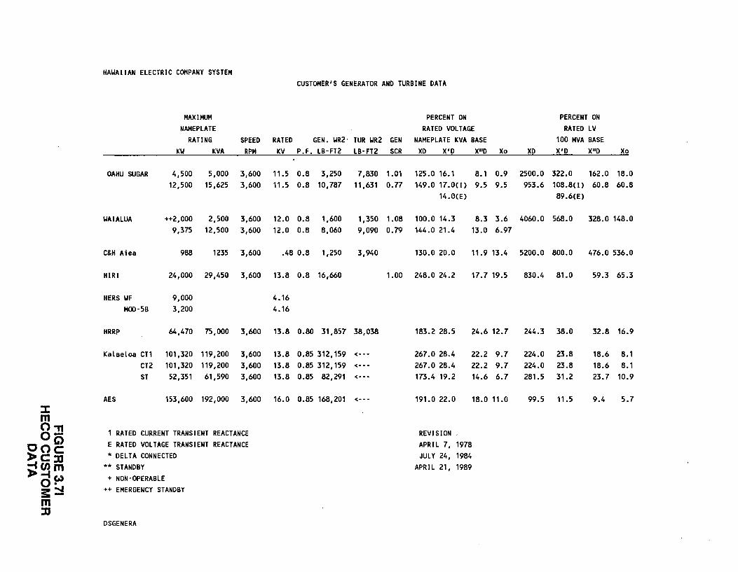
HAWAIIAN ELECTRIC COMPANY SYSTEM CUSTOMER'S GENERATOR AND TURBINE DATA
MAXIMUM PERCENT ON PERCENT ON NAMEPLATE RATED VOLTAGE RATED LV
RATING SPEED RATED GEN. WR2· TUR WR2 GEN NAMEPLATE KVA BASE 100 MVA BASE KW KVA RPM KV P.F. LB-FT2 LB-FT2 SCR XD X'D X"D Xo XD X'D X"D Xo
OAHU SUGAR 4,500 5,000 3,600 11.5 0.8 3,250 7,830 1.01 125.0 16.1 8.1 0.9 2500.0 322.0 162.0 18.0 12,500 15,625 3,600 11.5 0.8 10,787 11,631 0.77 149.0 17.0(1) 9.5 9.5 953.6 108.8(1) 60.8 60.8
14.0(E) 89.6(E)
WAIALUA ++2,000 2,500 3,600 12.0 0.8 1,600 1,350 1.08 100.0 14.3 8.3 3.6 4060.0 568.0 328.0 148.0 9,375 12,500 3,600 12.0 0.8 8,060 9,090 0.79 144.0 21.4 13.0 6.97
C&H Aiea 988 1235 3,600 .48 0.8 1,250 3,940 130.0 20.0 11.9 13.4 5200.0 800.0 476.0 536.0
HIRI 24,000 29,450 3,600 13.8 0.8 16,660 1.00 248.0 24.2 17.7 19.5 830.4 81.0 59.3 65.3
HERS WF 9,000 4.16 M00-5B 3,200 4.16
HRRP 64,470 75,000 3,600 13.8 0.80 31,857 38,038 183.2 28.5 24.6 12.7 244.3 38.0 32.8 16.9
Kalaeloa CT1 101,320 119,200 3,600 13.8 0.85 312,159 <--- 267.0 28.4 22.2 9.7 224.0 23.8 18.6 8.1 CT2 101,320 119,200 3,600 13.8 0.85 312,159 <--- 267.0 28.4 22.2 9.7 224.0 23.8 18.6 8.1 ST 52,351 61,590 3,600 13.8 0.85 82,291 <--- 173.4 19.2 14.6 6.7 281.5 31.2 23.7 10.9
AES 153,600 192,000 3,600 16.0 0.85 168,201 <--- 191.0 22.0 18.0 11.0 99.5 11.5 9.4 5.7 :::c m o.,
1 RATED CURRENT TRANSIENT REACTANCE REVISION 0(5 coc E RATED VOLTAGE TRANSIENT REACTANCE APRIL 7, 1978
l>c:a *DELTA CONNECTED JULY 24, 1984
)!(J)m ** STANDBY APRIL 21, 1989 -lw + NON-OPERABLE 0· s::::! ++ EMERGENCY STANDBY
m :D
DSGENERA
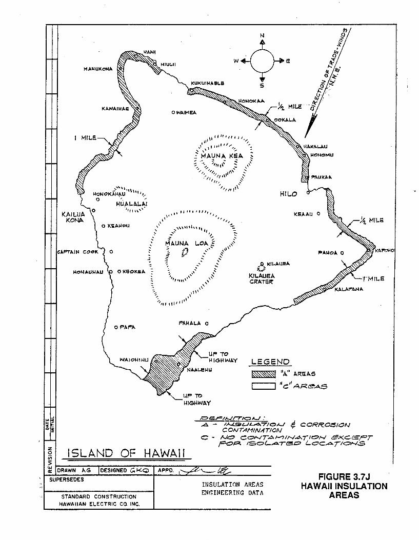
I Mll.S.
.... ' '''''' 1-lONOKrH~U 11111,.-
0 '. ~
HUAL.A.L.AI ·,," \\,~·
OWAIMEA
.... ::. \,,, , ,, ;. ,,, ,,, , I I I, '
,,'
.. , .. \~ ,,
N
Kll.AUEA CRA7E~
HILO
KEAAU 0
0 PAt",._ PI>.HALA 0
~ ISLAND OF HAWAII
LEGEND
~ 11A" b.REAS
''c'' AP.eAs
/::::>CJ=IJ..Jr710AJ: ..A - IA./.St .. n . ..1'4.-TIOAJ l/. CORROSION
CONTA/'1/NATION C - NO Cc:»--TAI-?INA/.IOf-.1 C:><.CEFT
poP. ISOl-.;Cr../(!!!0 LOC.;Cr..T!ON.S
> ~--------~--------------~--------~~--~~------------~ DRAWN A.G DESIGNED G.KQ APPD. i
SUPERSEDES
STANDARD CONSTRUCTION HAWAIIAN ELECTRIC CO INC.
INSULATION AREAS ENGINEERING DATA
FIGURE 3.7J HAWAIIINSULATJON
AREAS
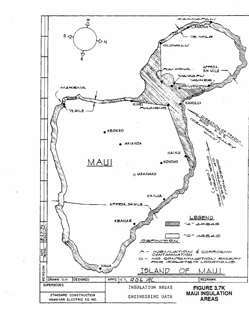
s N
e I(!;;OKE!O
e WAIAI<OA
HAIKU
AI"P~OX.. 8/4 MILE
MAUl eKOKOMO .
o MAKAWAO
APr-R'Ol<..3/4 MILE!.
LEGEND
A- /~SL./~"7/0.!--J c!/. CORP..O..:SION CONI AM/NATION
C:: - ~0 C0"'-./"7.4"-"'fii-J~"7'10~ EEXC.E..;=-r P'O~ t.e.c:u .. -.::o.-r-e;.r=:::; i-OC-6.-riO /-../.!!!!:;.
SUPERSEDES INSULATION /\REAS FIGURE 3.7K MAUl INSULATION
AREAS STANDARD CONSTRUCTION
HAWAIIAN ELECTRIC CO INC. ENGINEERING DATA
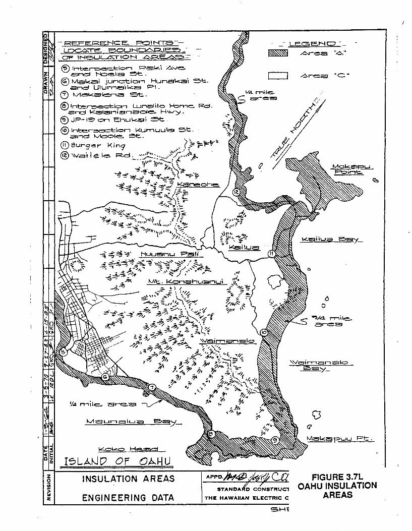
SV31:1V NOil.V1nSNI nHVO
1L"£ 3~:~n~1:1
·~d
0 Q
!HS
tfl.tfO E)NI~33NIE)N3
Stf3~tf NOIJ.tf1nSNI
n H'Y'o d 0 c::J N¥"1 c;I
:II
~ ii'i 5 z
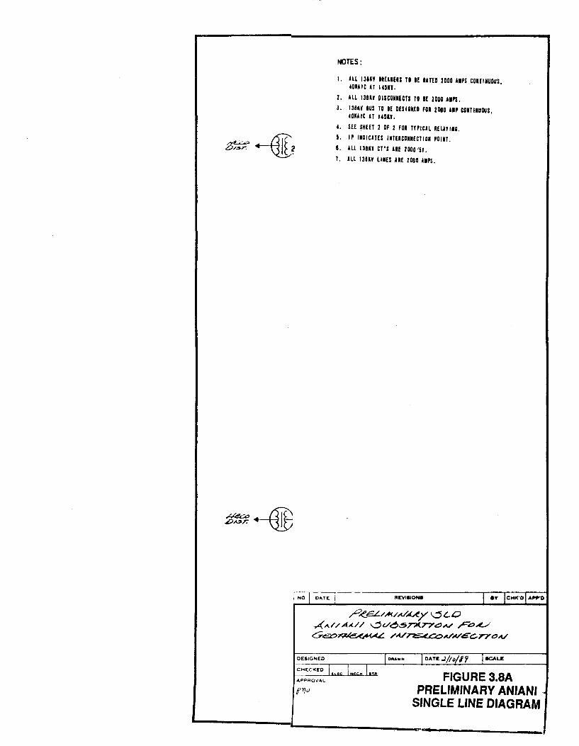
NOTES:
I. All 13UY IIEU£1S TD If llTEO 2000 AlPS COITIMUOUS, ~OlA IC AT 14m.
2. ALL IJU¥ 0 ISCOIIfCTI TO If 2000 JII'S.
3. IJUY IUS TO If OfSI811£0 fOI 2000 liP COITIIUOUS, ~ou tc AT um.
~. SfE SHEET 2 OF 2 fOI TYPICAL RfiJYIIG.
5. IP IIDICATES INTERCOIIECTIOI POIIT.
8. All 138U CT'S ARE 2000l5f.
1. ALL 138U LilES UE 2000 AlPS.
_P,ee:L./.M/.V~y ~(..0 ~A//AA..// ....:>v~.STJI(T7~A./ r~~ Ue::c>~ /A./~Co..VN'cC.TYOA/
DESIGNED I 0"AWH
CHEC><e:D l .u:. Lu....l.u.u APPROVAL
I DATI: ..2/lt>/i'i J.a.u:
FIGURE 3.8A PRELIMINARY ANIANI
SINGLE LINE DIAGRAM
CHAPTER 4: RELIABILITY
The HECO system serves the island of Oahu. Because of its
isolation, there are no interties between the HECO system and any
other electric power system. This unique situation requires
reliability factors and operating practices not ordinarily found
in more conventional interconnected electric systems.
4.1 SYSTEM CHARACTERISTICS
The island environment requires HECO to operate its system with
sufficient spinning reserve so that the inadvertent loss of the
most heavily loaded unit will not result in the loss of power to
any customer. The units on spinning reserve must react quickly
and restore the system frequency to at least 58.5 Hz upon loss of
the most heavily loaded unit. The amount of spinning reserve with
quick response time (that which can be achieved in three ( 3)
seconds) is defined as "quick load pick-up" by HECO.
The maximum sized unit currently on the HECO system has a normal
top load of 142 MW. This is the maximum amount of spinning
reserve HECO intentionally has synchronized to the system.
The variation in load during a 24 hour period requires that
cycling units be taken
presently 9:00 pm to 7:00
off-line during the off-peak hours,
am. The HECO Load Dispatcher directs
this operation. Further, base-loaded units are designed to have
the capability of reducing load to about one-half of rated
capacity. It would be highly desirable that the Project be
capable of meeting similar operating requirements.
4-1
00844F-1869600-Dl
4.2 HECO RELIABILITY
The island environment demands a high reliability from existing
HECO generating units. Typically, the annual forced outage rate
for all generating units ranges from a low of two percent to a
high of four percent. The equivalent availability factor runs
between 90 percent and 92 percent.
The average service availability index (ASAI) is a measure of the
reliability of the HECO distribution system. The ASAI is defined
as the average number of customers (#) on the HECO system times
the period hours (PH) minus the customer hours lost (CHL) divided
by the average number of customers times the period hours.
Mathematically, the ASAI is expressed as follows:
ASAI = (#) x (PH) - (CHL) ( #) X (PH)
From 1984 to 1988, the annual ASAI on the HECO distribution system
has ranged from a low of 99.951 percent to a high of 99.983
percent.
4.3 ASSUMPTIONS AND CONSIDERATIONS
It is anticipated that the DEVELOPER will install capacity in
increments of between 25 MW and 50 MW. Ideally, the Project
capacity will be brought on-line to match HECO's needs. Such a
schedule is likely to enhance and optimize the value of the
Project's capacity.
It is suggested that the size of the largest geothermal generating
unit not exceed about 125 MW. This is smaller than the HECO
largest unit of 142 MW. However, such an increment will ensure
that HECO spinning reserve and quick load pickup will be adequate
4-2
00844F-1869600-Dl
Jlil!i
-
to cover the loss of the largest Project generating unit or loss
of one component of the HVDC transmission system.
The reliability of the power delivered to HECO will be measured at
the point of interconnection to the HECO grid (see Section 3.8).
4.4 RELIABILITY ASSESSMENT
For the purpose of calculating reliability, the Project is defined
as all components involved in the generation and delivery of
electrical power to the point(s) of interconnection. This
includes, but is not limited to, the geothermal wells, the
wellf ield ( s) , turbine genera tors, switchgear, substation ( s) ,
overhead transmission lines, submarine cables, and converter
terminals. The higher the Project reliability, the more valuable
this capacity will be to the HECO system.
The following indices of the Project reliability and availability
must b~ provided in the Proposal:
a. Forced Outage Rate (FOR)
b. Equivalent Forced Outage Rate (EFOR)
c. Availability Factor (AF)
d. Equivalent Availability Factor (EAF)
HECO will use the Electric Power Research Insitute UNIRAM
availability assessment methodology to evaluate the reliability of
the proposed design. Information on UNIRAM can be found in
Reference 1.
The above indices shall be defined and calculated in accordance
with ANSI/IEEE Standard 762 (Reference 3). The equations and
4-3
00844F-1869600-Dl
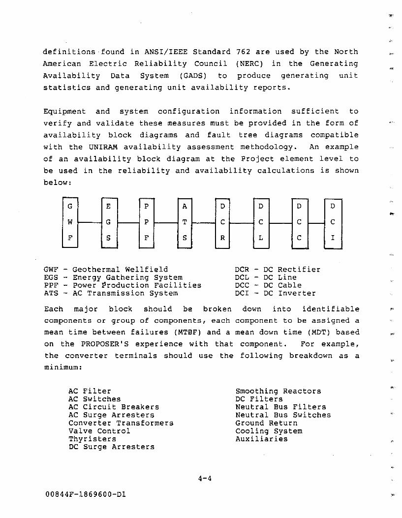
definitions found in ANSI/IEEE Standard 762 are used by the North
American Electric Reliability Council (NERC) in the Generating
Availability Data System (GADS) to produce generating unit
statistics and generating unit availability reports.
Equipment and system configuration information sufficient to
verify and validate these measures must be provided in the form of
availability block diagrams and fault tree diagrams compatible
with the UNIRAM availability assessment methodology. An example
of an availability block diagram at the Project element level to
be used in the reliability and availability calculations is shown
below:
G E p
w .,__-~G p
F s F
GWF - Geothermal Wellfield EGS - Energy Gathering System PPF - Power Production Facilities ATS - AC Transmission System
D D
c .,___-1 c
R L
OCR - DC Rectifier DCL - DC Line DCC - DC Cable DCI - DC Inverter
Each major block should be broken down into identifiable
components or group of components, each component to be assigned a
mean time between failures (MTBF) and a mean down time (MDT) based
on the PROPOSER'S experience with that component. For example,
the converter terminals should use the following breakdown as a
minimum:
AC Filter AC Switches AC Circuit Breakers AC Surge Arresters Converter Transformers Valve Control Thyristers DC Surge Arresters
00844F-1869600-Dl
4-4
Smoothing Reactors DC Filters Neutral Bus Filters Neutral Bus Switches Ground Return Cooling System Auxiliaries
This information should be submitted in the form of input data
files to the UNIRAM version 2.0 program on a hard copy and either
3.5-inch (720 KB or 1.44 MB) or 5.25-inch (360 KB) floppy disks
formatted for the IBM Personal Computer.
It is expected that equipment MTBF and MDT statistics for all
components used in support of the Proposal will correspond to
utility records available in the NERC GADS and other sources such
as PROPOSER experience, International Conference on Large High
Voltage Electric Systems (CIGRE) reports, and the Edison Electric
Ins.titute (EEI) reports. Any statistics used in support of the
Proposal that are significantly different from those in GADS (see
Reference 2), or other published sources, should
verifiable evidence. In addition, values for
hours and rolling maintenance should also
be accompanied by
scheduled outage
be supported by
verifiable evidence for purposes of evaluating availability
factors and equivalent availability factors.
4.4.1 GEOTHERMAL WELLF!ELD RELIABILITY
Geothermal wellfields in the KERZ probably represent the least
known factor in the information available for this Project. An
adequate data experience matrix for an assessment of reliability
of KERZ geothermal wells will likely come only out of KERZ
multiple well production history. At inception, wellfield
reliability can be addressed by selecting a energy producing
capacity in excess of the connected electrical generating
capacity. The magnitude of excess energy producing capacity
should be based on PROPOSER'S integration of estimated well
deliverability, well cost, actual electrical generation require
ments and power pricing mechanisms. PROPOSER should, however,
include corrosion/erosion effects on wellfield equipment in the
reliability calculations. PROPOSER should also include in the
reliability evaluation the potential impacts of lava flows and
earthquakes on the wells.
4-5
00844F-1869600-Dl
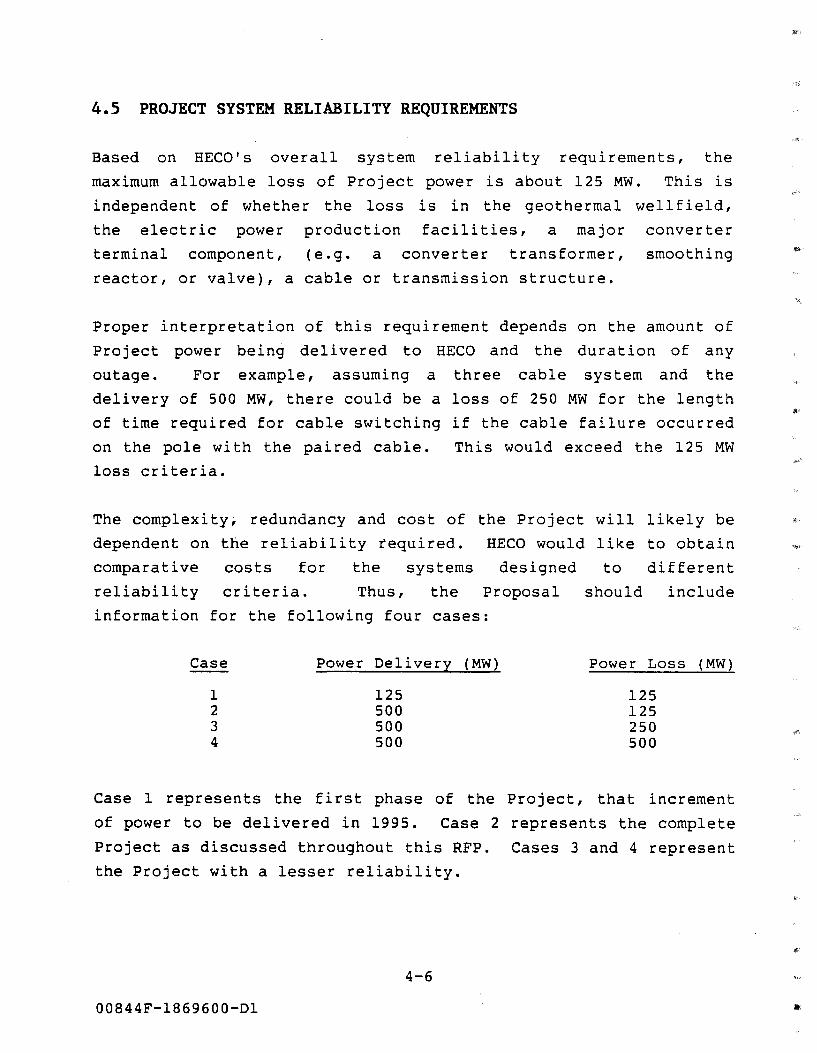
4.5 PROJECT SYSTEM RELIABILITY REQUIREMENTS
Based on HECO's overall system reliability requirements, the
maximum allowable loss of Project power is about 125 MW. This is
independent of whether the loss is in the geothermal wellfield,
the electric power production facilities, a major converter
terminal component, (e.g. a converter transformer, smoothing
reactor, or valve), a cable or transmission structure.
Proper interpretation of this requirement depends on the amount of
Project power being delivered to HECO and the duration of any
outage. For example, assuming a three cable system and the
delivery of 500 MW, there could be a loss of 250 MW for the length
of time required for cable switching if the cable failure occurred
on the pole with the paired cable. This would exceed the 125 MW
loss criteria.
The complexity; redundancy and cost of the Project will likely be
dependent on the reliability required. HECO would like to obtain
comparative costs for the systems designed to different
reliability criteria. Thus, the Proposal should include
information for the following four cases:
Case Power Delivery (MW) Power Loss (MW)
1 125 125 2 500 125 3 500 250 4 500 500
Case 1 represents the first phase of the Project, that increment
of power to be delivered in 1995. Case 2 represents the complete
Project as discussed throughout this RFP. Cases 3 and 4 represent
the Project with a lesser reliability.
4-6
00844F-1869600-Dl
Information on the calculated costs and reliability for the four
cases should be presented on Exhibit 4. SA. The project design
will very likely be different for the four cases. Exhibit 4. 5B
requests a descriptive comparison of the four designs. Costs for
Cases 1 and 2 are requested in Section 7.1, Exhibits 7.1A, B and
C. The equivalent exhibits should be provided for Cases 3 and 4
as Exhibit 4.5C and 4.5D, respectively.
Proposer should also submit the reliability data to be used in the
UNIRAM assessment methodology that support the above analysis.
4.6 REFERENCES FOR CHAPTER 4
1.
2.
Electric Power Research Institute. User's Guide for the
UNIRAM Availability Assessment Methodology: Version 2.0.
EPRI Report AP-5897-CCM.
Reference 1 is available from Research Reports Center, Box
50490, Palo Alto, California 94303, (415) 965-4081. Required
software is available by contacting Larry Coit, Electric
Power Research Insitute, P.O. Box 10412, Palo Alto, CA 94303,
(415) 855-8972. Please refer to the Hawaii Geothermal/
Interisland Transmission Project when contacting EPRI.
North American Electric Reliability Council.
Availability Reports, various years.
Generating
Reference 2
Reliability
08540-6601.
is available from the North American Electric
Council, 101 College Road East, Princeton, NJ
Telephone 609-452-8060.
A listing of all system/component cause codes within each
major equipment group can be found in Appendix B of the NERC
GADS Data Reporting Instructions.
4-7
00844F-1869600-Dl
3. American National Standards Insitute. IEEE Standard Defini-
tions for Use In Reporting Electric Generating Unit Reliabil
ity, Availability, and Productivity (1987). ANSI/IEEE
Standard 762.
4-8
00844F-1869600-Dl
CHAPTER 5: POWER DELIVERY AND SCHEDULE
The delivery of Project power to HECO will be determined by its
need ~or power and the rate of development of the geothermal
resource. This Chapter describes HECO's forecasted power
requirements and the scheduling information to be included in the
Proposal.
The Project can provide HECO with both capacity and energy. HECO
will require additional baseload and cyclable capacity after 1994.
The amount of baseload capacity that HECO could accept is
determined by the minimum load on the system and that portion of
this minimum load reserved for generation on Oahu. The amount of
deliverable capacity in excess of this minimum is dependent upon
the DEVELOPER's ability to cycle the Project. Depending on the
time of day, HECO could agree to accept up to the full 500 MW
Project capacity.
HECO will accept the energy represented by the PPA capacity. The
amount of additional energy that HECO could absorb depends on the
system load. The PROPOSER has the option of varying the Project's
design and development to maximize the sale of capacity and energy
to HECO.
5.1 CAPACITY
HECO's present (spring, 1989) system capacity is 1277 MW. The
system's peak load is growing by about 2. 2
Purchases from Independent Power Producers
accommodate this growth through 1994. HECO has
percent per year.
are expected to
to begin planning
additional capacity by the end of 1990 to accommodate the
post-1994 growth. Hence the timing for this RFP.
5-l
00844G-1869600-Dl
HECO' s capacity requirements beyond 1994 are dependent on the
amount of installed generation, load growth, unit retirement and
level of acceptable risk. Risk, as defined by HECO, is a
probabilistic index which indicates the probability of having
insufficient capacity to meet the peak demand for the day. HECO
uses a minimum acceptable risk index of 4.5 years per day, which
may be restated as having insufficient capacity to meet the peak
demand for one day out of every 4.5 years.
The estimated capacity requirements are shown on Figure 5.1A as a
step function based on 25 MW increments of generatin addition.
This estimate has been prepared for only the ten year period of
1995 to 2005, during which HECO plans to add approximately 500 MW.
Superimposed on the HECO capacity requirements is a hypothetical
Project power supply capability curve, shown as a smooth curve for
clarity although it most likely would be a step function. As can
be seen, this hypothetical uniform development of the Project
results in an excess of Project capacity in the years up to 2001,
after which a shortfall exists until the full 500 MW capability is
on line.
The PROPOSER has other options. Referring to Figure 5. 2A, the
Project could install 230 MW of baseload capacity by 1995. With
respect to baseload capacity demand after 1995, the Project could
then add baseload capacity only if HECO experiences an increase in
minimum load beyond that which is currently anticipated. However,
if any portion of the Project power can be cycled, additional
cycling capacity (beyond additional baseload) can be added up to
the full 500 MW Project development. The reliability of delivery
must be consistent with HECO's maximum loss of generation criteria
of about 125 MW, see Chapter 4.
5-2
00844t-1869600-Dl
''"
5.2 ENERGY
Forecasted peak and minimum HECO annual loads are shown on Figure
5.2A. The beginning point for PPA negotiations for power delivery
will be the curves presented in this section.
5.2.1 PEAK LOAD
Peak loads for HECO are expected to increase from the present
level of 1080 MW to about 1660 MW in 2008, assuming a steady
growth rate of 2. 2% per year. There should be no constraint on
sale of Project power at peak load levels, as can be seen in
Figure 5.2A.
The PROPOSER may assume that any amount of Project power in excess
of the level absored by HECO at minimum load (see Section 5.2.2)
will be purchased by HECO as peaking power when such power is
delivered during on-peak periods. On-peak hours are presently
·7:00 am to 9:00 pm.
5.2.2 MINIMUM LOAD
Minimum load growth on Oahu is estimated to continue at a rate of
1.6% per year. This is shown on Figure 5.2A, along with another
curve that is offset by 230 MW. This 230 MW is HECO's judgment as
to the minimum generation that must be maintained on Oahu,
accounting for contractual commitments and HECO's generation
needed to stabilize the system. This assumes that HECO's reheat
units will be modified to maximize their cycling capability by
1995.
This lower curve of Figure 5.2A represents the amount of Project
power that HECO could absorb during minimum load conditions. It
could be considered the potential baseload for the Project. Also
shown on Figure 5.2A is the same hypothetical Project power supply
5-3
00844G-1869600-Dl
capability used on Figure 5.1A. As can be seen, HECO could absorb
more than the hypothetical Project capability from the initiation
of power delivery through the year 2000. In fact, at minimum load
HECO could absorb approximately 230 MW in 1995, rising to about
250 MW in the year 2000. HECO cannot absorb all the potentially
available Project power at minimum load from approximately the
year 2001 through the year 2020.
The PROPOSER should strongly consider and describe methods of
reducing Project power flow to HECO during light load periods and
other possible situations when HECO will require less power than
would be available from the Project. Refer to Section 7.1.2 for
further discussion on this subject.
5.2.3 DAILY AND YEARLY VARIATIONS
The previous RFP sections present only the instantaneous peak and
minimum demand on the systems. The amount of power that can be .,,
cycled is determined by the daily and yearly variations. Figure
5.2B presents HECO daily variations for four conditions, February
and August weekdays and weekends. Information on HECO yearly
variations can be determined from Tables 5.2A, B and c.
5.3 PROPOSED SCHEDULE
Sections 5.1 and 5.2 present HECO's best assessment of its
capability to accept power from the Project using the assumptions ~
for Project development stated and HECO • s present forecast for
load growth, new generation units on order, unit retirement
schedule and modification of reheat units for cycling duty. The
PROPOSER should consider this information in the preparation of
the Proposal. However, if the information with its assumptions
adversely affects or influences the economic feasibility of the
Project (c. f. Section 7 .1. 6), the PROPOSER should identify the
problems and propose an alternate schedule. The PROPOSER is
S-4
00844G-1869600-Dl
strongly urged to use HECO's capacity and energy requirements
shown on Figures 5.1A and 5.2A if at all possible.
Several times throughout the RFP reference is made to a first
phase of Project power of about 125 MW. This is only an
assumption for purposes of describing the
PROPOSER is free to select a different value.
first phase. The
The PROPOSER should
complete Exhibit 5.3A for whatever power delivery schedule is used
in the Proposal, for the first phase and the complete Project.
These values of Exhibit 5. 3A should also be used for all other
Proposal submittals.
HECO requires schedule-related information to validate commitments
made by the PROPOSER. This should be in the form of a milestone
or summary schedule. HECO is not specifying the exact form this
schedule should take, as it will vary with PROPOSER'S scheduling
software computer program and the exact mix of Project equipment
proposed. However, the timeline should include, as a minimum, the
information on the sample Exhibit 5.3B included in the RFP. One
Exhibit 5.3B should be included for the first phase of power shown
on PROPOSER'S Exhibit 5.3A, and one for the complete Project. The
amount of detail shown on the Project exhibit can be less than
that shown for the first phase exhibit.
This milestone schedule should include all steps necessary to
obtain access to and permission to use the geothermal resource,
acquire the necessary surface rights and rights of way and secure
permits for the major elements of the project. Specification
preparation, procurement, fabrication and installation should be
specifically included for at least the major items, as shown on
the sample Exhibit 5. 3B. PROPOSERS may include more i terns, if
desired. Major civil and structural construction activities
should also be shown, as well as testing and start-up.
5-5
00844G-l869600-Dl
The PROPOSER is encouraged to present a qualitative/quantitive
defense of PROPOSER'S Exhibits 5.3B on Exhibit 5.3C.
5-6
00844G-1869600-Dl
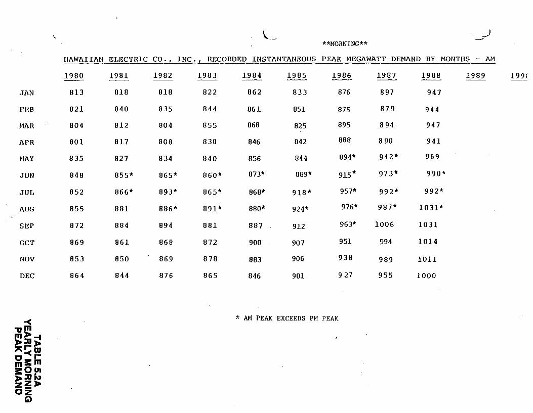
JAN
FEB
MJ\R
APR
HAY
JUN
JUL
AUG
SEP
OCT
NOV
DEC
-< -a£! ~:u~ "!<m c,r mo::am a:Ocn ,..:uN zZ,.. cz
Q
\. \,. ___ _) --**MORNING**
111\WAI IAN ~~LEC'l'HlC CO. , INC •• , HECOHDED INS'l'ANTANEOUS PEAK HEGAWATT DEMAND BY MONTHS - 1\M
1900 1901 1902 1903 1904 1985 1906 1987 1988 1989 199( -- --813 0.18 018 822 862 833 876 897 947
821 040 835 844 06.1 851 875 879 944
004 812 804 055 068 825 895 8 94 947
801 Bl7 BOB 038 B46 842 B8B 8 90 941
835 B27 B34 840 B56 B44 B94* 942* 969
B4B 055* 865* 060* 073* BB9* 915* 973* 990*
852 066* 893* 065* B6B* 910* 957* 992* 992*
B55 801 806* 091* 8BO* 924* 976* 9B7* 1031*
B72 884 894 081 887 912 963* 1006 1031
B69 861 860 872 900 907 951 994 1014
853 850 869 870 883 906 938 989 lOll
864 844 876 865 846 901 9 27 955 1000
* Mf PEAK EXCEEDS PM PEAK
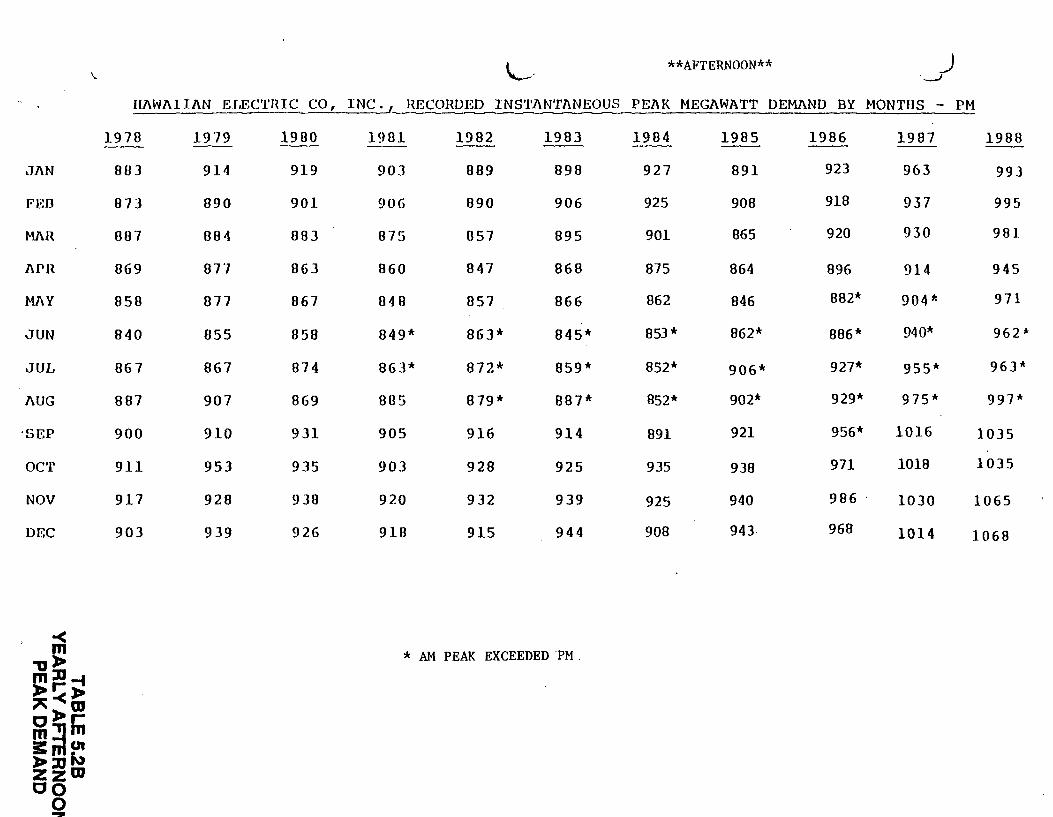
Jl\N
FED
M.l\H
1\PH
Ml\Y
JUN
JUL
1\UG
·SEP
oc·r
NOV
DEC
~ "0,. ~i!-t "-<~ o,.r m::!Jm s:;nc.n ,.:u~ zzm co
0 z
\. "--· **AFTERNOON** _) ._.J
111\Wl\I Il\N JU,EC'l'HIC CO, IN<~ RECORDED INS'l'l\NTJ\NEOUS PEAK MEGAWATT DEMJ\ND BY MONTHS - PM
1978 1979 1980 1901 1982 1983 1984 1985 1986 1987 1980
863 914 919 903 889 898 927 891 923 963 993
873 890 901 906 890 906 925 908 918 937 995
087 804 883 875 057 895 901 865 920 930 981
069 077 863 860 847 868 875 864 896 914 945
858 877 867 848 857 866 862 846 802* 904* 971
840 055 858 849* 863* 845* 853* 862* 886* 940* 962*
867 867 874 863* 872* 859* 852* 906* 927* 955* 963*
887 907 869 805 879* 887* 852* 902* 929* 975* 997*
900 910 931 905 916 914 891 921 956* 1016 1035
911 953 935 903 928 925 935 938 971 1018 1035
917 928 938 920 932 939 925 940 986 1030 1065
903 939 926 918 915 944 908 943 968 1014 1068
* AM PEAK EXCEEDED ·pM .
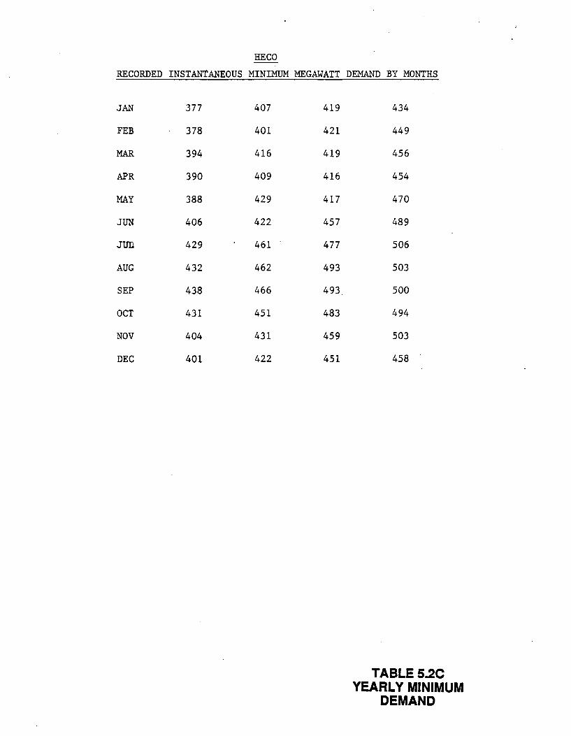
HECO
RECORDED INSTANTANEOUS MINIMUM MEGAWATT DEMAND BY MONTHS
JAN 377
FEB 378
MAR 394
APR 390
MAY 388
JUN 406
JUD 429
AUG 432
SEP 438
OCT 431
NOV 404
DEC 401
407 419
401 421
416 419
409 416
429 417
422 457
461 477
462 493
466 493
451 483
431 459
422 451
434
449
456
454
470
489
506
503
500
494
503
458
TABLE 5.2C YEARLY MINIMUM
DEMAND
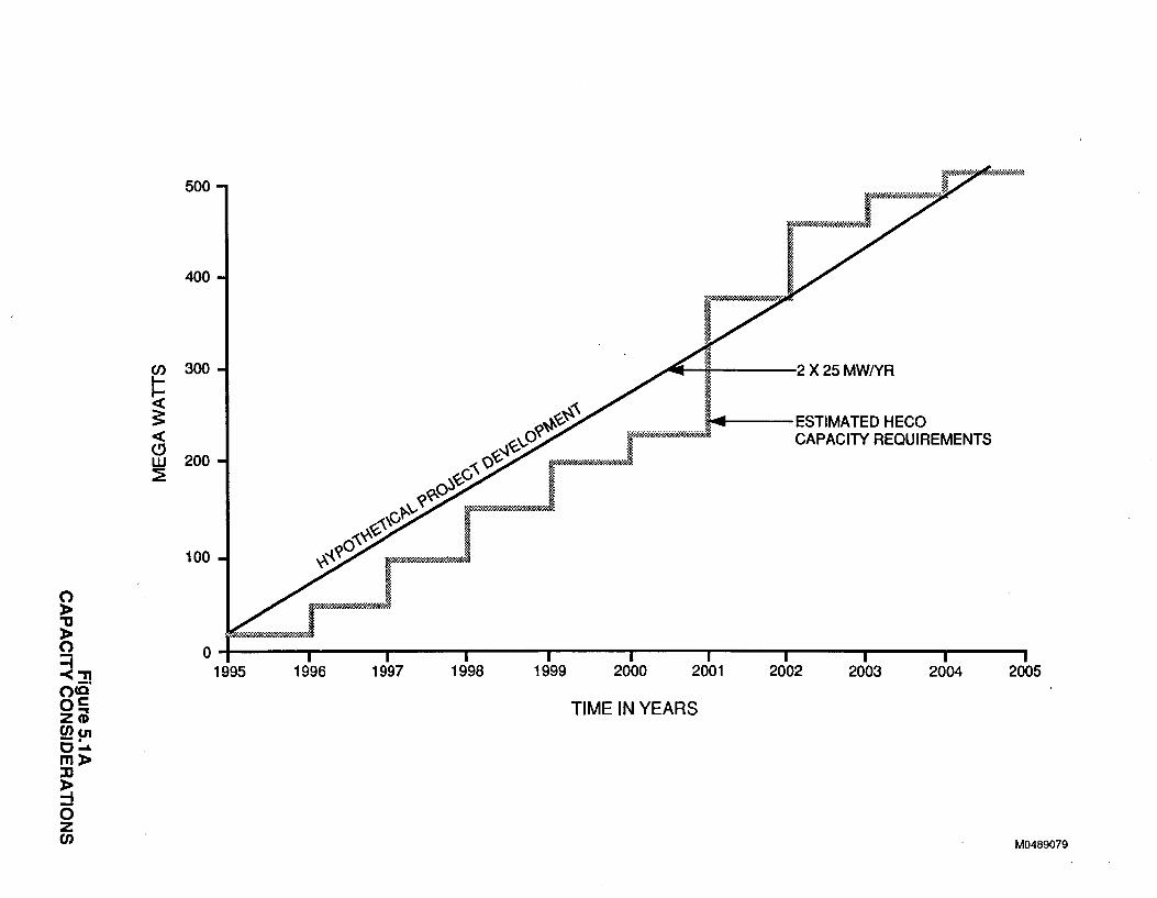
500
400
en 300
~ ~~~~-------2X25MWNR
~,<(,~'\ ~~-... -----ESTIMATED HECO <( C) w ::E
~<(,'vO~~~·-~;»;;;<w-<=»m;;>.w.:-.<cl CAPACITY REQUIREMENTS
'1-'-'?~d»~JG~, J • ~\G .
100 ~··
200
0~ I I 1995 1996 1997 1998
I 1999
I I 2000 2001
TIME IN YEARS
I 2002
I 2003
I 2004
I 2005
M0489079
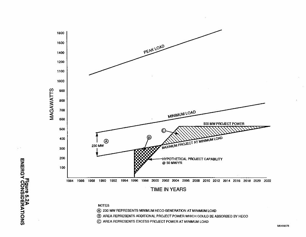
(/)
~ 3: < (!} < ~
m z m :0 G)
-<"'I o-oca z~ en CD -m C· mllol :ol>
~ 0 z en
1800
1600
1400
1200
1100
1000
900
800
700
600
500
400
300
200
100
HYPOTHETICAL PROJECT CAPABILITY @ 50MW/YR
1984 1986 1988 1990 1992 1994 1996 1998 2000 2002 2004 2006 2008 2010 2012 2014 2016 2018 2020 2022
TIME IN YEARS
NOTES
@ 230 MW REPRESENTS MINIMUM HECO GENERATION AT MINIMUM LOAD
@ AREA REPRESENTS ADDITIONAL PROJECT POWER WHICH COULD BE ABSORBED BY HECO
@ AREA REPRESENTS EXCESS PROJECT POWER AT MINIMUM LOAD M048907B
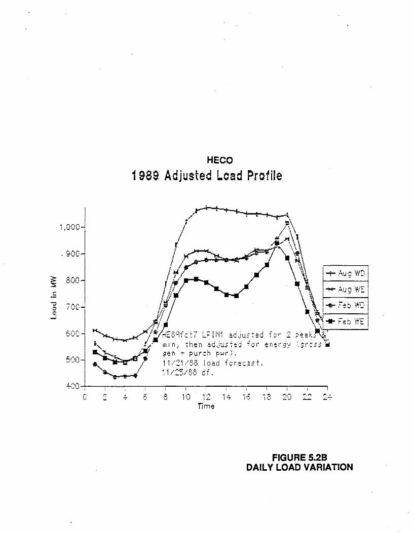
1,000
- 900
:::
HECO
1 989 Adjusted Lead Profile
c 10 1 ·;o 14 1..' 1..:..
Tim~
~
-+- .A.1J ·: W'D i v 1
16 ~~ 21CI ,.,....., ,..., .. l ·:_~ - ..::..-:--
FIGURE 5.28 DAILY LOAD VARIATION
CHAPTER 6: PERMIT AND ENVIRONMENTAL INFORMATION
The State of Hawaii Department of Business and Economic
Development has prepared a summary of available permit and
environmental information that they believe is applicable to this
Project. This is included in the RFP as Appendix B.
6.1 PERMITS
The Proposal shall identify all state, federal and local permits
required or which may be required in order to successfully
complete all stages of the Project. The Proposal shall also
provide estimates of the time required to obtain each permit and
shall state the basis for such estimates. The PROPOSER should
account for the public hearing requirements when developing the
permitting timeline. The Proposal shall also discuss the effect
of the timing of the permit process on the ability of .the
DEVELOPER to deliver power from the Project in a timely fashion,
consistent with the requirements for power described elsewhere in
this RFP. Each major "milestone" in the state and federal
permitting process should be included in the Exhibits 5. 3B (See
Section 5.3).
Appendix B.l is a summary, prepared by the State of Hawaii, which
sets forth the State's current understanding of the permitting
regimes likely to apply to the Project. This summary is intended
as guidance and is not intended to relieve the PROPOSER of the
responsibility to conduct an independent analysis of the
permitting regime applicable to the Project. Although this
summary is as thorough as possible to provide maximum assistance
to the PROPOSER, HECO makes no representations that Appendix B is
a complete list of necessary permits, and makes no warranty with
respect to legal issues arising under the laws and regulations
discussed therein.
6-1
00844H-1869600-Dl
The Governor of Hawaii has offered the State's assistance in
obtaining permits. See Governor Waihee's letter to H.D.
Williamson (attached following the Executive Summary). This offer
by the State does not relieve the PROPOSER from identifying the
permit requirements and schedule in the Proposal.
6. 2 ENVIRONMENTAL INFORMATION
Available environmental information will be assembled in the
public document room for review by interested Proposers.
The PROPOSER should indicate in the Proposal whether any
environmental, cultural or socioeconomic issues materially affect
the planning of essential aspects of the Project. The Proposal
should include a plan, with a schedule, for fully analyzing and
addressing these issues.
Appendix B.2 is a summary, prepared by the State of Hawaii, of the
available environmental information.
6-2
00844H-1869600-Dl
CHAPTER 7: COMMERCIAL INFORMATION
.7.1 FINANCIAL PROJECTIONS
This section describes the financial projections requested of the
PROPOSER. These projections will be a major factor in HECO' s
evaluation of the Proposal. For purposes of this section,
financial projections include both the PROPOSER'S pricing
proposals to HECO and the Project costs used to determine the
Project's financial feasibility.
All recipients of this RFP who posses the technical, managerial
and financial expertise to develop this Project are strongly urged
to submit a Proposal. HECO is interested in receiving a wide
variety of approaches to this Project development. To this end,
HECO will evaluate each Proposal received. Projected costs of the
Project's power are just one factor in the evaluation, albeit a
major one.
7.1.1 AVOIDED COSTS
Power purchase agreements entered into by HECO have been based on
some form of avoided cost. Avoided costs typically have two
components, a capacity payment and an energy payment, occasionally
varying with the time of day and season of the year. HECO' s
latest avoided cost filing was in late 1988. It is included here
as Attachment 7.1A.
HECO does not intend that the current avoided cost formula will
dictate the pricing formula for this Project. The pricing terms
of any PPA entered into for this Project will be based on a power
cost formula developed specifically for this Project, taking into
account its unique character. This Project represents a much
larger block of power than HECO has considered in the past. It
7-1
00844I-1869600-Dl
also has very unique character is tics compared to those power
sources available to HECO now or in the near-term future. State
policy considerations may affect the cost formula. (See Governor
Waihee' s letter attached following the Executive Summary.) The
costs to HECO of alternative sources of power, however, will
affect HECO's evaluation of the Proposals submitted in response to
this RFP.
The following sections ask for detailed cost information so that
HECO may fully evaluate the Proposals and to provide a starting
point for the financial portion of the negotiations that will lead •
to a PPA.
7.1.2 PROJECT SCENARIOS
From HECO's standpoint, the ideal power source is as desc~ibed in
Section 1.3. It should be highly reliable and fully dispatchable,
i.e., available in the quantities and only in the quantities that
HECO requires at any moment. Both qualities may increase the
effective cost of the Project's power, but may also increase the •
value of that power to HECO.
HECO strongly invites PROPOSERS to investigate and propose means
for maximizing reliability and dispatchability. For example, if
the PROPOSER can find a load leveling use of geothermal resources,
it could increase the DEVELOPER'S revenue and may increase
dispatchabili ty and reliability of the power made available to
HECO. If such a load leveling use involves the sale of power,
such power sales shall be only to HECO.
PROPOSERS are asked to present in some detail all scenarios that
they may have developed in preparing their Proposal. Letters or
memoranda or documentation of a similar nature should be presented
to support the validity of the scenario. Because such
documentation may be highly confidential, the PROPOSER may choose
7-2
00844!-1869600-Dl
'"
to provide information at the Proposal stage which does not
identify the party or parties to such actual or anticipated
agreements (c. f. Section 2. 7) • However, HECO will require all
pertinent information be available as a basis for negotiation.
In the financial analyses requested in the following sections,
PROPOSERS should present as a base case the Project costs for a
stand-alone Project. Additional exhibits should then be used to
show the costs to HECO from a Project developed under an
alternative scenario. PROPOSER is strongly urged to present all
scenarios developed in the course of preparing the Proposal. A
scenario that may not in PROPOSER'S eyes be the most
cost-effective may have facets that may make it more valuable to
HECO than the PROPOSER may realize. (The State of Hawaii may also
have an interest in such alternate scenarios).
7.1.3 GEOTHERMAL RESOURCE COSTS
The financial exhibits which follow request capital costs and
operating and maintenance expenses for the geothermal wellfields.
As discussed in Section 3.1.6, HECO anticipates that PROPOSERS may
not have access to the geothermal resources prior to submittal of
the Proposal. HECO does not intend to consider in the evaluation
the ownership or lease related costs so as to evaluate all
Proposals on an equivalent basis and thereby maintain a
competitive environment for this Project.
to preclude any PROPOSER from HECO, however, does not wish
reaching accommodations with
leaseholder or surface owner.
any major geothermal mineral
If the PROPOSER has secured options
or letters of intent for sufficient geothermal resources, that
should be identified. HECO also does not require that a Proposal
include an exclusive right to an individual geothermal mining
lease. The same lease interest could be represented in many
different Proposals.
7-3
00844I-1869600-Dl
HECO plans to normalize the geothermal costs between Proposals.
There are spaces on both the capital and operations and
maintenance exhibits for geothermal ownership or lease related
costs. These should be completed if possible. HECO has available
to it extensive geothermal exploration and production cost
information. This information will be used to evaluate any
information provided in the Proposal.
Proposals should include drilling and maintenance costs,
regardless of whether PROPOSER has an ownership or lease resource
position.
PROPOSERS must begin negotiations to obtain access to sufficient
geothermal resources if they are selected to the short list. HECO
will not sign a PPA unless the DEVELOPER has obtained access to
the geothermal resource. HECO may cooperate in efforts to obtain
geothermal resource rights, as appropriate. The State also has a
. very high interest in the utilization of the State-issued ~
geothermal leases for the Project.
Attachments 7 .lB and 7 .lC are letters from existing geothermal
leaseholders. They contain information which HECO believes may be
of interest to PROPOSERS in preparing responses to the RFP. This
material has been included in the RFP solely for purposes of
information. HECO in no way endorses or warrants the information
contained in these materials, nor should the inclusion of these
materials in the RFP be construed as a request by HECO that the
statements by third parties contained in these materials be taken
into consideration in the preparation of a response to the RFP.
7.1.4 CAPITAL COSTS
The estimated capital cost of the
development of the complete system:
Project is to be based on
wells, energy gathering and waste
geothermal wells, injection
disposal systems, power
7-4
00844I-1869600-Dl
4246S
REQUEST FOR PROPOSAL
FOR THE
GEOTHERMAL/INTER-ISLAND TRANSMISSION PROJECT
ISSUED BY HAWAIIAN ELECTRIC COMPANY, INC.
HONOLULU, HAWAII MAY 1989
production facilities, overland transmission lines, submarine
cables, converter terminals and any other equipment and facilities
that may be required. The PROPOSER is requested to present
capital costs as a function of time. The PROPOSER should use
Exhibit 7.1A to present this information.
This exhibit is a condensation of the National Association of
Regulatory Utility Commissioners (NARUC) code of accounts. (This
code of accounts is essentially identical to the Federal Energy
Regulatory Commission code of accounts.) The format of Exhibit
7 .lA is being used so that HECO may compare Project costs with
other data available to HECO.
A separate Exhibit 7.1A should be provided for the first phase of
the Project as well as for the complete Project. The first phase
is defined as that increment of power which will be available by
December 1995. There will likely be an overlap between the first
phase and later phases, and HECO desires to clearly understand the
PROPOSER'S plans for the first phase. An Exhibi~ 7.1A should be
provided for the base Proposal (stand-alone Project) and also for
each individual scenario considered by the PROPOSER.
Exhibit 7.1A is based on an escalation rate of five percent/year,
compounded. PROPOSERS may include additional Exhibits if they
believe that this escalation rate is inappropriate. The PROPOSER
is encouraged to footnote the analyses to clarify portions which
may be unclear.
The Proposal should also provide the assumptions, data, and
algorithms used in constructing financial statements (examples:
inflation rates, interest rates, depreciation schedules,
utilization rates and product prices) in sufficient detail to
allow HECO to replicate the financial pro formas submitted. This
information should be provided for Exhibits 7.1A, Band C.
7-5
00844I-1869600-Dl
PROPOSERS who are unfamiliar with the NARUC code of accounts
should refer to Reference 1. A copy of this document is in the
public document room. If, upon review, questions remain, they
should be submitted under the procedures described in Section 2.2.
7.1.5 OPERATION AND MAINTENANCE COSTS
The operation and maintenance (O&M) costs should be provided for
the entire Project. Drilling of replacement production and
injection wells, as well as reworking wells, should be treated as
an O&M cost. There should also be specific allowances for the
energy gathering system, power production facilities, overland and
submarine transmission, converter terminals and any other equip
ment or facilities costed on Exhibits 7.1A.
The PROPOSER is requested to present O&M costs as a function of
time in the format provided in Exhibit 7.1B. A separate Exhibit·
7.1B should be included for the first phase of the Project as well
as one for the complete Project and se-parate Exhibits for each
scenario. There is more ambiguity with regard to the definition
of some O&M costs than with capital costs, so the PROPOSER is
encouraged to provide an explanation of assumptions used in
preparing the Exhibits 7.1B and to detail the operating plans
summarized on the Exhibits. In all cases, fixed and variable
costs should be clearly identified.
7.1.6 PROPOSED PRICE FOR POWER
The PROPOSER should complete an Exhibit 7.1C for the first phase
of the Project as well as an Exhibit 7.1C for the complete
Project. Again, the PROPOSER should complete a separate Exhibit
7.1C for the base case and for each alternative scenario
evaluated. Exhibit 7.1C should be supported by Exhibits 7.1A and
B so that the numbers on Exhibit 7 .lC can be reproduced. The
PROPOSER is strongly urged to also supply a qualitative/quanti-
7-6
00844I-1869600-Dl
tative analysis detailing the PROPOSER'S perception of the
financial and economic feasibility of the project. Exhibit 7. 3A
is provided for this purpose but is unstructured as HECO does not
want to force a PROPOSER into what may be an inappropriate mold to
best present the PROPOSER'S case.
7.1.7 OPERATIONAL CONSTRAINTS AND EFFECTS ON REVENUE
There may be situations where the PROPOSER is concerned that some
present or future action on the part of HECO, the State of Hawaii
or some other party may adversely affect the operation of the
Project and thus the revenue stream. The PROPOSER is encouraged
to highlight these concerns on Exhibit 7.1E so that they may be
discussed with PROPOSER during the evaluation phase.
7.2 CONTRACTUAL PROVISIONS
7.2.1 POWER PURCHASE AGREEMENT
This subsection describes the general terms and conditions that
HECO expects to be included in a PPA (or related documents, if
appropriate) entered into between HECO and a successful PROPOSER.
HECO intends to negotiate contracts with no more than two
PROPOSERS before a final selection is made and a con tract ( s) is
executed.
The PPA will establish the contractual rights and obligations of
the parties pursuant to which the DEVELOPER will deliver and HECO
will purchase electric energy and capacity from the Project. In
general this means, but is not limited to, the establishment of
terms and conditions that will assure HECO of reliable power with
a high availability factor from a geothermal powerplant or
powerplants located on the island of Hawaii and delivered to and
purchased by HECO at a designated point of interconnection on the
island of Oahu. It is anticipated that such energy and capacity
7-7
00844I-l869600-Dl
will be made available by an agreed upon time and for an agreed
upon term. It is also HECO's expectation that the purchase price
to be paid by HECO for power under the PPA will not exceed HECO's
avoided cost at the time of power delivery. In addition, HECO
will wish to specify in the PPA (or related documents): (1) the
circumstances (including limitations) when such capacity and/or
energy would be provided or curtailed; (2) those guarantees,
warranties and security arrangements required by HECO of the
DEVELOPER (and such other parties that might serve as guarantors ~
to the obligations of the DEVELOPER) that will operate to ensure
performance of the DEVELOPER'S obligations to supply power to
HECO; and (3) insurance coverage, damages provisions, indemnifica-
tion rights, and other negotiated provisions including HECO's
right to operate the Project under certain circumstances, designed
to provide a remedy to HECO for the DEVELOPERS non-performance
according to the PPA.
7.2.2 GENERAL DESCRIPTION OF TERMS AND CONDITIONS TO POWER PURCHASE AGREEMENT
The selected PROPOSER(S) and HECO will attempt to negotiate a PPA
that includes, but may not be limited to, the following general
provisions (the specific language of such provisions will be the
subject of negotiations):
• Term of agreement - 30 years - with right of the parties
to negotiate a longer term or the extension of a
completed term, the right of HECO to defer or cancel
delivery of energy or capacity from the Project and
rights of HECO to purchase the Project or components of
the Project upon expiration of the term or extended
term;
• Price for delivered energy during startup and testing
and then for delivered energy and available capacity at
7-8
00844I-1869600-Dl
•
the date of in-service operation of the Project to be
negotiated between the parties to the PPA;
Milestone schedule of tasks to be performed by the
DEVELOPER with such schedule to be made a part of the
PPA; failure to meet any milestone may be considered an
event of default and could result in termination of the
contract or such other remedy as provided by the terms
of the PPA;
• Guarantees, warranties and security agreements that are
intended to insure the performance of obligations
undertaken by the DEVELOPER;
• Specified liquidated damages if the Project does not
meet agreed upon milestone dates, performance standards
or other conditions or circumstances recognized and
agreed upon by the parties to the PPA;
• Rights of HECO to evaluate construction plans and
specifications, schedules, testing data, operation data
and performance data of the Project; to operate the
Project or any components of the Project if certain
prescribed circumstances exist; and to curtail
acceptance of electricity in the event of system emergency or other specified conditions;
• Events of default and remedies for events of default,
including termination of the PPA as well as agreed upon
rights and remedies and such other remedies as afforded
the parties by operation of law and in equity;
• Interconnection to HECO's transmission system with costs
to interconnect to be borne by the DEVELOPER; provisions
for metering, telemetering, testing and special
7-9
00844I-1869600-Dl
•
•
arrangements to safely interconnect into the HECO
transmission system~ and
Insurance that provides
limits for projects of
normally ~ccepted coverage
the magnitude contemplated;
geothermal reservoir insurance coverage or other agreed
upon forms of protection for failure or inadequate
production of the geothermal resources to be utilized;
and such other indemnification provisions as may be
agreed upon by the parties to the PPA.
7.2.3 DESCRIPTION OF THE REQUIRED GUARANTEE STRUCTURE FOR THE
PROJECT
The capacity and energy produced and delivered by the Project is
needed to meet the anticipated requirements of HECO's customers.
To best ensure that the electEic power from the Project will be
delivered at the time and in the manner prescribed in this RFP,
and t0 provide evidence and assurances of a PROPOSER'S ability to
perform as outlined herein, HECO seeks to obtain reasonable and
adequate performance guarantees from the PROPOSER. HECO's
expectations concerning the substantive requirements of these
guarantees are set forth in this section. These guarantees will
be set forth in the PPA, or may be set forth in other documents as
the parties deem appropriate. Other specific terms expected to be
included in the PPA are also set forth in other sections of this
RFP.
In evaluating any Proposal, HECO will consider the adequacy of
performance guarantees of the PROPOSER, or of other parties in
support of the PROPOSER of the proposed Project. Those
performance guarantees should act to mitigate HECO's risks, which
relate to HECO's obligations to provide adequate, safe and
reliable electric service to its customers while maintaining the
operational stability of its system.
7-10
00844I-1869600-Dl
'''"
..
...
••
In addition, HECO will evaluate the adequacy of guarantees in the
form of damages for non-performance. The damages which HECO would
sustain as a result of the proposed Project's non-performance and
failure to meet these guarantees are difficult to measure .by
easily predictable standards. Therefore, HECO anticipates that
its remedies for the non-performance of the DEVELOPER will include
liquidated damages based upon HECO's best estimates of damages it
might sustain in the event of failure to meet certain guarantees.
This section of the RFP is intended to provide the PROPOSER with
information as to the type, manner and degree of guarantees
required of the PROPOSER and the extent of obligations of the
PROPOSER and related parties which HECO believes are necessary in
order for HECO to confidently pursue the purchase of energy and
capacity from the Project. The descriptions provided in this
section are descriptive and informational only and are not
intended to be a· complete listing of all those provisions which
may be a part of the PPA or of other Project documents to be
negotiated with HECO. In addition, HECO reserves the right to
include in the PPA negotiations revisions or changes to the
provisions described in this section, based upon HECO's evaluation
of the Proposals.
7.2.3.1 Milestone Schedule
A milestone schedule of tasks to be performed by the DEVELOPER
should be provided in the Proposal to be finalized and included in
a PPA (see Section 5.3). The schedule must address the following:
licensing and permitting approvals; site acquisitions; archi teet
and engineering selections; detailed facility design; equipment
procurement through the bid, selection and award processes;
deli very and installation of critical components and equipment;
arrangements for both short-term construction financing and
permanent financing; interconnection and transmission agreement(s)
(if applicable); geothermal resource acquisition; geothermal
7-11
00844I-1869600-Dl
resource verification; and testing, start-up and in-service dates
of the geothermal powerplant(s), transmission system and
electricity converter stations.
The proposed schedule, after negotiation, will be included in the
PPA. Failure to meet the milestone schedule contained in the PPA,
unless otherwise agreed to, will be considered an event of
default. Depending upon the final milestone schedule agreed upon
by HECO and the DEVELOPER, such event of default may result in
termination of the PPA, liquidated damages, takeover and
completion and/or operation of the Project by HECO or its
assignees, or such other remedies as may be available at law or in
equity.
7.2.3.2 Right of HECO to Defer or Cancel
HECO will seek to include provisions in the PPA which would allow
HECO to· defer the Project's in-service date, or to cancel the
Project or portions thereof, if HECO determines that the capacity
additions to be provided by the Project should be deferred or
canceled because projected load growth or the need to replace
existing capacity in Oahu has changed rna ter ially from current
projections, or because other currently unforeseen events occur
which necessitate HECO taking such action. HECO and the DEVELOPER
will mutually agree upon the terms and conditions for such
postponement or cancellation as well as any fees, penalties or
similar charges to be paid in the event HECO must exercise such
right of deferral or cancellation.
7.2.3.3 Security Interests
HECO will seek a subordinated security interest in any escrow or
reserve accounts established in connection with financing for the
Project. Such security interests will serve to secure, in part, t
the DEVELOPER'S obligations to HECO pursuant to the PPA.
7-12
00844!-1869600-Dl
7.2.3.4 Equipment Guarantees
Equipment, process or
individual suppliers.·
be assignable to HECO
system guarantees are to be provided ~y the
The right to enforce such guarantees should
in the event HECO shall exercise rights to
complete or operate the Project or any portions thereof.
7.2.3.5 Guarantor Commitments
To insure completion of the Project, HECO may also seek the
following from the DEVELOPER:
Depending upon the proposed business structure of the DEVELOPER,
it may be necessary to seek a guarantee of performance from a
third party or parent organization of a DEVELOPER or party related
thereto. Such a party should have resources sufficient to provide
a guarantee for an agreed upon monetary amount which is related to
a level of completion of the Project.
In the alternative, the DEVELOPER would be required to provide an
unconditional irrevocable direct pay or standby letter of credit,
or bond issued by a bank acceptable to HECO, in form and substance
acceptable to HECO.
7.2.3.6 Loss or Reduction of Service
This RFP specifies that the PROPOSER should describe the expected
time for delivery of power and the level of performance and
reliability required of the proposed Project in order to meet the
needs of HECO (see the description in Chapter 5). With respect to
those specifications, the PROPOSER should consider the following:
Reduced (less than stated) availability of capacity from the
Project would cause severe operational impacts on HECO' s system
which may result in economic and load constraints that are
7-13
00844I-1869600-Dl
•
unplanned and unacceptable to HECO. The expected availability
from this Project is set forth in Section 5.1. Proposals should
contain guarantees by the PROPOSER that the Project's design and
equipment will perform as stated. In the event that such
performance is not attained on average in each and any contract
year or portion thereof, the DEVELOPER will be required to pay to
HECO in liquidated damages an agreed upon sum for each one-tenth
(1/10) of a percentage point that the availability of the Project
falls below the level guaranteed by the DEVELOPER.
When accepting relatively large amounts of capacity as proposed
for this Project, HECO must be able to depend on regular delivery
of such capacity. Unplanned reductions (less than stated) of
capacity or reductions with insufficient notice to HECO will
result in economic and operational hardships that are unacceptable
to HECO and its customers.
The DEVELOPER must warrant and guarantee that the Project, and all
associated components thereof, will have and maintain the ability
to continuously produce and deliver an agreed upon capacity (plus
or minus one percent) to the metering point for the contract
period. The contract period will commence after a specifically
stated period for testing and start-up, with agreed capacity to be
as requested by HECO's dispatchers, between 0.98 leading and 0.85
lagging power factor at the metering point.
The DEVELOPER will be required to pay specified liquidated damages
to HECO for any reduction in capacity from the agreed upon amount
until the deliverable capacity can be raised to the contractually
required levels.
Scheduled maintenance of the Project, and all components thereof,
should be coordinated with HECO. Prior to July of each year, the
DEVELOPER will be required to submit for review and comment by
HECO an initial schedule of expected energy delivery periods for
7-14
00844I-1869600-Dl
•
fr
the sixty (60) month period beginning with January of the
following year. The schedule shall state·the estimated periods of
operation, number of anticipated and scheduled shutdowns or
reductions of output and the reasons therefor, and the proposed
dates and durations of scheduled maintenance requiring shutdown or
reduction in output of the Project. HECO will seek compensation
related to HEC0 1 s cost of replacement power in the event any
scheduled outage exceeds the time planned for such outage.
Where it is determined that a condition exists at the Project
which will have a rna ter ially adverse physical impact on HECO 1 s
electric system or the equipment of HECO 1 s customers and which
requires, in HEC0 1 s sole judgement, a change in electricity
deliveries by the Project, the DEVELOPER will be required to
suspend or reduce deliveries and, if immediate danger to personnel
or electrical system equipment exists, HECO will be able to
remotely separate the Project from the HECO system. Where the
operation of the Project is causing or contributing to the adverse
condition, the DEVELOPER, at its own cost, shall be required to
modify its electric equipment or operations to the extent
necessary to promptly resume full deliveries of electricity to
HECO.
If the Project trips off-line in excess of an agreed upon number
of times each year, the DEVELOPER shall be assessed agreed upon
liquidated damages.
7-15
00844!-1869600-Dl
7.2.3.7 Right to Purchase Project (or any Components thereof) or to Extend Term of the.PPA
In order to ensure continuity of deliveries of the capacity and
energy of the Project for the benefit of HECO's customers, HECO
shall seek to establish rights in the PPA to purchase the Project
or any components of the Project (including the transmission
system and/or the geothermal powerplant(s}) and/or to extend the
term of the PPA. This RFP is not to be interpreted as a solicita
tion on the part of HECO of an ownership interest in the Project.
Should the DEVELOPER desire to dispose of its right, title or
interest in the Project, in whole or in part, other than through
the sale and leaseback of the Project or other assignment or
disposition for purposes of financing the Project, or any
component or part thereof, HECO shall retain a first right to
purchase the Project, or any component thereof, from the
DEVELOPER.
At an agreed upon time during the term of the PPA, HECO shall have
the right to seek an extension of the term of the agreement.
7.2.4 DESCRIPTION OF INSURANCE REQUIREMENTS
The DEVELOPER shall, at its own expense, acquire and maintain, or
cause to be maintained, for the mutual benefit of HECO and the
DEVELOPER the insurance herein specified and such other insurance
as may be deemed appropriate in the circumstances and shall
furnish to HECO Certificates of Insurance evidencing such
insurance as of the effective dates established in the PPA and
throughout the term of the contract. The DEVELOPER shall also
provide evidence of insurance, as applicable, upon each annual
renewal. Such certificate shall provide for 60 days prior written
notice to HECO of any policy cancellation or modification. The
DEVELOPER shall agree to notify HECO of any material changes in or
7-16
00844I-1869600-Dl
cancellation of any policy prior to the effective date of such
change or cancellation. The adequacy of the coverage afforded by
the required insurance shall be commensurate with the size of the
Project, and shall be subject to mutual review by HECO and the
DEVELOPER ·from time to time, and, if prudent and in keeping with
electric utility industry standards, the DEVELOPER shall forthwith
increase such coverages and/or limits to the extent required, the
costs of such increased coverages and/or limits to be borne by the
DEVELOPER. HECO shall be named an additional insured under the
policies described below to the extent applicable.
If the PROPOSER believes that any of the insurances described in
the following sections are not commercially available or available
only with an extremely high premium, the PROPOSER should so state
in the Proposal and supply the necessary documentation to support
the PROPOSER'S position.
7.2.4.1 Worker's Compensation and Employer's Liability
This coverage
disability and
shall
other
include
similar
worker's ·compensation,
insurance required by
temporary
applicable
Hawaii state or federal laws. If exposure exists, coverage
required by the Longshore and Harbor Worker's Compensation Act (33
u.s.c. 901-952) and the Jones Act (46 u.s.c. 688) should be
included. Additionally, coverage should include a voluntary
compensation and employer's liability endorsement for employees
not subject to the worker's compensation laws. The agreement will
establish employers' liability coverage limits for bodily injury
by accident and bodily injury by disease.
7.2.4.2 General Liability Insurance
This coverage should include either comprehensive general
liability or commercial general liability insurance covering all
operations by or on behalf of the DEVELOPER. Such coverage should
7-17
00844I-1869600-Dl
•
•
provide insurance for bodily injury and property damage liability
and should include coverage for:
• Premises, operations, and mobile equipment,
• Products and completed operations,
• Owners' and contractors' protective liability,
• Contractual liability insuring the obligations assumed
by the DEVELOPER resulting from the PPA,
• Broad form property damage (including
operations),
completed
• Explosion, collapse, and underground hazard, and
• Personal injury liability.
7.2.4.3 Automobile Liability Insurance
This insurance should include coverage for owned, leased and
non-owned vehicles. Coverage should include liability for bodily
injury and property damage. If general liability insurance is
provided by a commercial general liability policy, then the
automobile liability insurance policy required herein should
include coverage for automobile contractual liability.
7.2.4.4 Builders All-Risk Insurance
As a minimum, HECO will require evidence of insurance for
earthquake, flood, tsunami, volcanic eruption or other natural
disaster perils, including coverage during transit, testing,
incidental storage, and delay costs, and coverage for structures,
equipment, buildings, improvements and temporary structures used
in construction, or as part of the permanent Project from the
start of construction through the in-service date. The coverage
should be no less than the full amount of replacement value of
property i terns covered (unless a lower value is agreed to by
HECO), subject to a reasonable deductible. In the event that it
is not possible to obtain coverage for all of the perils noted
7-18
00844I-1869600-Dl

herein, or the PROPOSER concludes that another means of protection
is more practicable, then the PROPOSER should describe the means
by which the protection sought by such insurance coverage might
otherwise be obtained. One purpose of this requirement is to
provide assurances to HECO that, if a natural disaster occurs
before or during construction, the DEVELOPER will have the
financial resources to complete the Project.
7.2.4.5 All-Risk Property/Comprehensive Boiler and Machinery Insurance (Upon Completion of Construction)
This insurance should provide all-risk property coverage
(including the perils of earthquake, flood, tsunami, volcanic
eruption, or other natural disaster) and comprehensive boiler and
machinery coverage against damage to the Project, or any
components thereof, in amounts not less than the full replacement
cost of the Project (unless a lower value is authorized by.HECO)
to restore the Project to its condition prior to the casualty loss
and subject to a reasonable deductible. Such policies should be
endorsed to require that:
a. Complete copies of each
required by or performed
provided to HECO.
inspection
for the
or other report
insurer shall be
b. The coverage afforded shall not be canceled or reduced
without prior written notice to HECO.
In the event that such insurance cannot be obtained for volcanic
eruption, for example, then the PROPOSER should propose some other
alternative method by which the full replacement cost of the
Project, or any component thereof which is the subject of the
casualty loss, will be guaranteed and assured.
7-19
00844I-1869600-Dl
7.2.4.6 Business Interruption Insurance (Upon Completion of Construction)
This insurance should provide coverage for all of the DEVELOPER'S
costs to the extent that they would not be eliminated or reduced
by the failure of the Project to operate (including, but not
limited to, rent or mortgage payments, geothermal resource lease
payments, interest and principal payments on loans or bonds, and
salaries and wages) for a period of at least twelve (12) months
after a reasonable deductible period or reasonable dollar
deductible.
7.2.4.7 Geothermal Reservoir Insurance
The PROPOSER should propose geothermal reservoir insurance
coverage or such other form of coverage as agreed to by HECO for
loss of the geothermal resources that are necessary to maintain
and operate the geothermal powerplant ( s) of the Project. Such
insurance should be available to cover the DEVELOPER'S costs of
drilling new wells, re-dr illing existing wells or taking such
actions which the DEVELOPER and HECO believe are
insure that sufficient geothermal resources exist at
and pressures required to operate the Project
electrical output levels required by the PPA.
necessary to
temperatures
at the net
It is recognized that geothermal reservoir insurance may not be
obtainable for this Project. If not available, then the PROPOSER
should propose, and fully describe, such alternative mechanism by
which HECO might be assured that the DEVELOPER will be financially
capable of drilling additional wells or taking such other actions ~
as may be necessary to maintain sufficient geothermal resources,
at the requisite temperatures and pressures, necessary to operate
the Project at agreed upon levels and durations.
7-20
00844I-1869600-Dl
7.2.4.8 Project Liability Errors and Omissions Insurance or Agreed Upon Alternatives
The PROPOSER should be adequately protected against project
liability errors and omissions on account of actions or inactions
of architects, engineers, contractors and subcontractors involved
in the design and construction of the Project. Evidence of this
protection may be provided through any one or more of the
following mechanisms: (i) construction contract(s) with the above
parties who have sufficient financial creditworthiness to cover
project liability errors and omissions; (ii) loan agreement(s)
with the above parties; or (iii) reserve account(s) which may be
used to correct material deficiencies associated with the Projecti
provided, however, that if HECO reasonably determines that the
above mechanisms would not provide protection similar to that
which would be provided through project liability errors and
omissions insurance for the Project with suitable liability limits
of insurance for a five (5) year period after the in-service date,
DEVELOPER will maintain or be required to maintain such Project
liabi~ity errors and omissions insurance.
7.2.5 REQUIREMENTS FOR INDEMNIFICATION
Requirements for indemnification by the DEVELOPER shall be
included in the PROPOSER'S Proposal.
7.2.6 DESCRIPTION OF EVENTS OF DEFAULT AND REMEDIES AVAILABLE DUE
TO DEFAULT
7.2.6.1 Events of Default
The PPA shall specify events that at any time during the operation
of the PPA shall constitute an "event of default". Subject to
further negotiation, the following events shall constitute
event{s) of default:
7-21
00844I-1869600-Dl
•
•
Failure to achieve any milestone requirement, unless
such milestone is waived in writing by HECO.
Failure of the Project to achieve an in-service date of
any increment where the cause of such failure is not the
occurrence of force majeure.
• Failure of the DEVELOPER to pay HECO any amount as and
when due under the PPA, if such delinquency is not _.,
remedied within a specified grace period after demand,
in writing, has been tendered by HECO.
• Failure of the DEVELOPER to use reasonable diligence in
operating, maintaining, or repairing the Project, or any
component thereof, such that the safety of persons and
property, HECO 1 s equipment, or HECO 1 s service to its
customers, is adversely affected, and/or failure to use
•
reasonable diligence within
notice and demand by HECO
failure.
a specified time after
for correction of this
Abandonment of the site or the discontinuance of design,
construction, startup, testing or power production,
plant operation or transmission of electricity for a
period of three (3) or more consecutive days, the last
twenty-four (24) hours of which shall be after notice to
DEVELOPER that it is not in compliance with the PPA.
• Failure of the DEVELOPER to meet the performance
requirements specified in the PPA beyond those covered
by liquidated damages.
• The taking of any action under any state or federal
bankruptcy or insolvency laws by or against the
7-22
00844I-1869600-Dl
"'
DEVELOPER, any consortium of which DEVELOPER is a
member, or any guarantor of the Project.
• The DEVELOPER becomes insolvent or unable to pay debts
as they become due; the holder or holders of any
obligations for money borrowed by the DEVELOPER
accelerates the repayment thereof; DEVELOPER does not
discharge an obligation for the payment of sums of money
above an agreed upon amount that has been ordered
pursuant to a final court order, judgement or decree
entered in any proceeding against the DEVELOPER or
DEVELOPER fails to make any payment and subsequently
becomes delinquent for materials or labor used in the
engineering, design, construction, maintenance or
operation of the Project; DEVELOPER defaults on any
obligation to a third party which results in an
acceleration of remedies available to that third party
which could result in a transfer either physically or
legally of, or a lien on, the Project, its assets or its
facilities.
• Without the approval of HECO, the DEVELOPER transfers,
conveys, loses or relinquishes its right to own or
operate the Project or to occupy the site where the
various components of the Project are located.
• Failure by the DEVELOPER to make all reasonable efforts
to restore the Project to full or substantially full
operating condition following any casualty loss.
• The security provided by or for the DEVELOPER and made a
part of the PPA becomes, or is reasonably likely to be,
substantially impaired.
7-23
00844!-1869600-Dl
• An event of default by the DEVELOPER under any of the
financing documents utilized in conjunction with the
financing of the Project occurs and HECO determines in
good faith that its rights under the PPA are likely to
be impaired as a result of the parties to the financing
of the Project exercising their remedies.
• The DEVELOPER fails to maintain in full force and effect
throughout the term of the PPA either the securities
specified in the PPA or the issuer of the securities
fails to pay to HECO any amount as and when due under
such securities.
• The DEVELOPER becomes involved in a labor dispute after
the in-service date which results in a shutdown or
reduction in output of the Project of more than 125 MW
for more than seventy-two (72) hours.
• The DEVELOPER fails to perform a material obligation of
the PPA not otherwise specifically referred to in this
section and such failure continues for a specified
period of time after written demand by HECO for
performance thereof.
7.2.6.2 Remedies Available Upon Default
Upon the occurrence of an event of default by the DEVELOPER, HECO
may, at its option, seek payment of damages from the DEVELOPER
(liquidated damages to be established for some events of default),
terminate the PPA and take over operation of the Project and/or
in.~titute such legal action or proceedings or resort to such other
remedies as it deems necessary.
HECO, at its option, shall have the right to assume all of the
DEVELOPER'S interests, rights and obligations in the Project to
7-24
00844I-1869600-Dl
...
the extent it is legally capable of doing so, to take over the
construction or operation of the Project and construct or operate
the Project during the period in which the foregoing assumption of
DEVELOPER'S interests, rights and obligations is being perfected
and to complete the construction of and/or operate the Project.
HECO may exercise, at its election, any rights and claims and
obtain any remedies it may have at law or in equity, including,
but not limited to, compensation for monetary damages, injunctive
relief and specific performance. The DEVELOPER will acknowledge
and agree that a failure to perform any of its obligations under
the PPA (other than obligations to make payments to HECO) would
cause irreparable injury to HECO and that the remedy at law for
any such failure or threatened failure would be inadequate.
Accordingly, the DEVELOPER will agree that HECO need not prove the
inadequacy of legal remedies in order to become entitled to a
temporary or permanent injunction or other equitable relief
specifically to enforce any such obligation.
7.3 INFORMATION ON PROPOSER
In evaluating Proposals submitted under this RFP, HECO will
require reasonable assurances that the PROPOSER has the financial
and management capability to develop and operate the Project in a
timely, financially sound and effective manner, consistent with
the other requirements of this RFP. HECO will not accept a
Proposal unless the Proposal demonstrates that the Project is
financially feasible and that the proposed management structure is
adequate to permit HECO to rely upon the expectation of successful
Project development to help meet its capacity planning
requirements. To assist HECO in this assessment, the Proposal
-must include: a full description of the identity, composition and
financial condition of the PROPOSER, a financing plan and a
detailed plan for management of Project development and operation.
7-25
00844I-1869600-Dl
7.3.1 PROPOSERS LEGAL IDENTITY AND COMPOSITION
Each Proposal must identify an entity currently in existence or
which will be in existence prior to contract negotiations who will
be responsible for the Project (the PROPOSER). The Proposal shall
contain a full description of the business activities, financial
Jll•
circumstances and management structure of such PROPOSER as ~·
described in the following sections.
If the entity is not in existence at the time the Proposal is
submitted, the Proposal must identify who will act for the entity
in responding to questions during the Proposal evaluation phase.
If the PROPOSER is a corporation, it must be a U.S. corporation
and the state of incorporation must be identified. All corporate
owners of this corporation must also be identified.
If the PROPOSER is a joint venture, the Proposal must identify all
participants and their percentage participation. Furthermore,
each Proposal shall identify those organizations or parties
responsible for .proposing and accomplishing all phases of the
proposed Project (the Project team).
The Project team includes the legal entity responsible for the
Project (i.e., the PROPOSER), the subcontractors, technology
licensors, and host-site offerers that are identified in the
Proposal. The Project team also includes those guarantors of
Project completion, lenders of funds to conduct the Project, and,
if appropriate, insurers of the Project. Where a legal entity has
been or will be created to conduct the Project, the participating
organizations or parties (partners, joint venture members, etc.)
are also considered to be Project team members.
To document the Project team agreement(s), each member of the team
should provide to HECO a legally binding agreement, or letter of
7-26
00844I-1869600-Dl
...
intent to reach such agreement, with the prospective participant
that clearly and explicitly states its respective role in the
Project and the nature of its relevant business relationship for
purposes of this Project. These documents should be signed by a
corporate official or other appropriate person authorized to
legally bind the aforementioned entities. These letters should be
included in the Commercial Proposal.
7.3.2 FINANCIAL REQUIREMENTS
7.3.2.1 Existing Entity
If the PROPOSER is an existing entity not formed specifically to
undertake this Project and is otherwise engaged in other business
activity, the PROPOSER must provide:
• current financial stat~ments for all business quarters
reported on in the current fiscal year (or the
immediately preceding ·fiscal year, if no quarterly
statements have been reported);
• an audited financial statement for the prior three
fiscal years; and
• a comprehensive description of the business activities
of the PROPOSER during the preceding five fiscal years;
and
• the most recent SEC form lOK that is available.
The PROPOSER may also provide such additional information as the
PROPOSER considers useful to HECO in evaluating the financial
ability of the PROPOSER to undertake the Project.
7-27
00844I-1869600-Dl
•
7.3.2.2 New Entity
If the legal entity (i.e. PROPOSER) came into existence, was
incorporated or was otherwise formed specifically to conduct this
Project, or will be formed prior to the selection of a Proposal by
HECO, the PROPOSER must provide:
• a complete, current list of all investors in the
PROPOSER;
•
•
•
such financial statements as may be available for the
PROPOSER;
audited
.7.3.2.1
audited
7.3.2.1,
PROPOSER
financial statements as described in Section
for each investor in the PROPOSER;
financ-ial statements as described in Section
for any predecessor organizations to the a
and for any organization with previous •·
investment interest in the PROPOSER;
• audited financial statements as described in Section
7.3.2.1 for any entity identified in the Project
financial plan or elsewhere in the Proposal as a
guarantor or possible guarantor of the Project;
• a description of the business relationships among the
investors in the Project;
• a copy of any agreements (or adequate summaries of any
agreements) establishing relationships among the
PROPOSER and investors and among the investors,
including joint venture and partnership agreements,
service supply agreements and similar matters; and
7-28
00844I-1869600-Dl
• the most recent SEC form lOK available for each
investor. If the investor is a non-U.S. entity, provide
equivalent information.
7.3.3 FINANCING PLAN
The Proposal shall include a financing plan for the Project which
shall identify the amount and proposed source of funds needed to
complete development of the Project and shall describe the
material terms and conditions under which the financing for the
Project would be obtained.
The financing plan shall describe the total projected financing
and financing costs for the Project, including a description of
material financial and economic assumptions such as interest and
discount rates. This description shall be specific, and shall
include a timetable indicating the amount of funding that must be
available in each Project year, and the plan for debt service and
return on equity for the.duration of Project operation.
The financing plan shall also be accompanied by an analysis of the
economic assumptions underlying such plan, sufficient to permit
HECO to conclude that the Project will be financially feasible if
developed pursuant to such financing plan.
The financing plan shall describe the proposed source of funds,
including the proposed allocation of debt and equity funding.
a) With respect to equity funding, the financing plan shall
to the fullest extent practicable:
• describe the extent of DEVELOPER contribution to
equity funds, and the source of such funds;
7-29
00844I-1869600-Dl
• describe the extent to which (and terms upon which)
other equity participants will be sought or have
been committed;
•
•
identify other possible sources of equity
participation, and the reliability of such other
sources;
identify any proposed broker and the form of equity
solicitation;
• provide all available evidence of the reliability
of other equity participants, including executed
agreements, certification of private financing,
firm letters of intent, or similar documentation or
adequate summaries of such evidence;
• identify other outstanding obligations of the
PROPOSER and other equity participants, including
liabilities, limitations, conditions and other
factors that affect or may affect the availability
of the PROPOSER'S funds for the Project;
• identify plans for supplemental equity financing;
• identify any special priorities or restrictions on
dividends or other forms of return of equity
investment necessary to secure debt financing;
• indicate whether the DEVELOPER or any other Project
participant will finance any portion of the equity
contribution on a recourse basis;
• identify any special terms and conditions, unique
to a Project of this size and character, which the
7-30
00844I-1869600-Dl
PROPOSER believes must be offered to equity
participants to permit financing of the Project
under the terms of the financing pla~. If the
PROPOSER concludes that no such special terms and
conditions exist, it should state the basis for
such conclusion.
b) With respect to debt financing, the financing plan shall
to the fullest extent practicable:
• identify the amount and character of debt financing
for the Project;
• describe the expected sources of such funds and the
basis for believing such funds will be available;
• provide evidence documenting the availability of
debt financing including letters of intent,
contractual agreements, certification of private
financing, or similar documentation or summaries of
such evidence;
• describe, to the extent possible, the types of
instruments expected to be used, and the essential
terms and priorities governing repayment;
• describe the amount and character of security,
including any collateral and guarantees;
• describe the types and estimated fair market value
of assets (if any) that will be pledged as
collateral for any outside financing;
• indicate whether, and the extent to which, the
DEVELOPER will seek state and local grants, loans
7-31
00844I-1869600-Dl
•
c)
or other funding or financial assistance (including
tax forgiveness or postponement}, the source of
such funds or financial assistance, and the
importance of the availability of such assistance
to the financial feasibility of the Project;
• describe guarantees or remedies upon default that
will be included in loan agreements;
•
•
•
The
•
describe any
persons that
guarantees of affiliated or other
the PROPOSER or other participants
expect to obtain;
describe what, if any, changes in ownership and
financing structure or operation of the Project are
expected to occur upon completion of the
development phase of the Project; and
identify any special terms and conditions that will
be required to provide sufficient debt financing
for the Project. If it is assumed that no special
terms and conditions are required, the basis for
that assumption should be described.
financing plan should also include:
a schedule of Project funding requirements
(combined debt and equity);
• identification of any likely variable terms that
could alter cash flow projections;
• the expected price for energy and capacity provided
by the Project; and
7-32
00844I-1869600-Dl
''"
lil·
I!
..
.,,
• sensitivity analyses indicating the effect of
reasonable Project delays on cash flow requirements
and overall financing costs.
HECO is aware that some of the information described above will
not be fully developed at the time of submission of a Proposal.
However, the PROPOSER should recognize that the assessment of the
Project's financial feasibility is critical to the overall
viability of the Project. Therefore, the thoroughness and
adequacy of the PROPOSER'S financing plan will be a material
consideration in HECO's comparative evaluation of Proposals
submitted in response to this RFP.
7.3.4 MANAGEMENT STRUCTURE
The Proposal shall include, to the fullest extent practicable, a
complete description of the management responsibilities that will
be borne directly by the DEVELOPER. It shall identify other
persons, in addition to the DEVELOPER, who will be responsible for
any phase of Project development (i.e. members of a Project team
inciuding proposed contract management, if any); a description of
the allocation of responsibility for management of Project
development; and a general management plan.
Legally binding agreements or letters of intent to reach such
agreements with the DEVELOPER and key members of the Project team
should be provided. In addition, the Proposal should identify, to
the fullest extent practicable, any other team members expected to
be added, and describe the timetable and method for obtaining a
binding commitment.
The Proposal should identify all major subcontractors, technology
licensors, host-site offerors, and geothermal resource owners who
will participate in the Project.
7-33
00844I-l869600-Dl
The Proposal should include a management plan for both Project
development and operation. This management plan should, as fully
as possible, provide:
• a description of the allocation of responsibility among
members of the Project team, including organizational
charts depicting organizational and functional relation
ships of key personnel within the corporate and/or
Project team structure;
• an organizational chart showing key personnel, with
man-hours and percentage of key personnel time that will
be devoted to the proposed Project;
• resumes of key personnel, describing education,
technical/management experience, and professional
qualifications;
• a description of key personnel's experience and success
with projects involving similar or related technologies,
and projects of similar scope or complexity; and
• a description of the allocation of responsibility for
operation of the transmission lines and associated
facilities, and a plan for operation of such lines and
facilities, including a description of any cooperative
relationship with HECO, if necessary, for ensuring ~
reliable operation of the facility.
The PROPOSER may also provide such additional information as the
PROPOSER considers useful in evaluating the management capability
of the PROPOSER to undertake the Project.
7-34
00844I-1869600-Dl
..
7.3.5 PRIOR EXPERIENCE
In those sections of the RFP that describe and discuss the PPA and
the management and financial structure of the PROPOSER, there are
a set of explicit questions and requests for detailed information
which will assist HECO in determining the qualifications of the
PROPOSER, and related parties, to undertake the Project sought by
this RFP. The PROPOSER is encouraged to respond in full to the
information sought by those sections of the RFP. The additional
questions set forth here are intended to provide HECO with further
information about the prior experience of the PROPOSER, or related
parties, in the development, construction or operation of similar
energy projects, including, most importantly, projects involving
geothermal resources or projects owned or operated by a
non-regulated entity selling electricity to a regulated utility.
To the extent that the PROPOSER has fully and directly addressed
these questions in other portions of the RFP, a cross-reference
may be appropriate.
• What experience has the PROPOSER, or a related party, had in
developing a project of the size and complexity proposed?
Please be specific in describing the type of project, whether
the PROPOSER, or related par.ty, was a DEVELOPER or
contractor, and whether the PROPOSER, or related party,
participated in financing the project or negotiating the
power purchase agreement, if any.
• Has the PROPOSER, or a related party, owned (including
current ownership), operated, or participated as a contractor
in the construction of a project which utilizes geothermal
resources. Please describe the project, the role of the
PROPOSER or related parties and location of the project.
7-35
00844I-1869600-Dl
Please provide a list of persons to contact who might discuss
the qualifications and performance of the PROPOSER or related
party with respect to the projects described above.
7.3.6 REGULATORY ISSUES
The PROPOSER should identify the regulatory requirements, if any,
that may affect the financing or management structure of the
Project. Specifically, the Proposal should indicate whether or
not federal law, including the Public Utility Holding Company Act
and the Public Utilities Regulatory Policy Act, or Hawaii state
law including Chapter 269, Hawaii Revised Statues and the PUC's
rules may or will affect the financing or management structure,
and how the proposed ownership and management structure is
adequate to address such issues. The PROPOSER should also
identify any other regulatory requirements, including permitting
of the Project, that may affect timely development and discuss how
the proposed management and organization structure will address
such issues, if any.
7.4 EVALUATION CRITERIA
The following business,
criteria will be applied
volume to be submitted by
management and financial evaluation
to evaluate the Commercial Proposal
the PROPOSER in response to this RFP:
7.4.1 FINANCIAL CONDITION, CAPABILITY TO FINANCE AND FINANCING PLAN
In assessing a PROPOSER'S financial capability and financing plan
HECO will:
• examine the adequacy and completeness of the plan to finance
the project;
7-36
00844I-1869600-Dl
lir
• assess the financial condition and capability of the proposed
funding sources to provide the equity and debt funding for
the project; and,
• determine the ability of the PROPOSER to initiate and
successfully conclude the financing for the Project,
(including meeting milestone schedules) as evidenced by prior
experience(s) of the PROPOSER or related parties in the
financing of projects of similar magnitude and complexity.
In analyzing the PROPOSER'S financing plan, HECO will also examine
the PROPOSER'S projections of the economic viability of the
proposed Project. To conduct this evaluation, HECO will:
• analyze the PROPOSER'S projections of cash generated from the
Project to determine if sufficient cash is available to cover
all costs of operation and debt service and to provide an
adequate overall incentive to sponsors; and,
• examine all receipt and disbursement items and other factors
which could affect cash flow.
HECO will not dictate economic assumptions such as interest rates
to be used by the PROPOSER in responding to this RFP. However, in
its comparative analyses of competing Proposals, HECO will make
adjustments in economic assumptions needed to ensure evaluation of
Proposals on a common basis. In addition, HECO may test the
reasonableness of the PROPOSER'S economic assumptions against
HECO' s business assumptions and, if appropriate, the views of
independent analysts consul ted by HECO for this purpose. The
PROPOSER, therefore, should provide the assumptions, data, and
algorithms used in constructing financial statements (examples:
inflation rates, interest rates, depreciation schedules,
utilization rates and product prices) in sufficient detail to
allow HECO to replicate the financial pro formas submitted. (See
7-37
00844I-1869600-Dl
Exhibits 7.1A, B and C) It will facilitate HECO's review if the
foregoing is provided on hard copy and in IBM-PC Lotus 1-2-3
magnetic diskette form.
7.4.2 ORGANIZATIONAL CREDENTIALS, AVAILABILITY AND QUALITY OF PROJECT PERSONNEL RESOURCES AS EVIDENCED IN THE MANAGEMENT PLAN
In assessing a PROPOSER'S management capabilities, HECO will
examine the experience and expertise of:
•
•
the PROPOSER and related parties in the development and
conduct of projects comparable to this Project;
key individuals in the project management;
• as identified by the PROPOSER, appropriate members of the
project team.
The management plan will be reviewed in terms of the following
factors:
• the experience of individuals with projects of similar size
and complexity who are designated as project managers and as
key project engineers with projects of similar size and
complexity;
7-38
00844I-1869600-Dl
II!!P
• the quality and composition of the PROPOSER'S technical team
responsible for reviewing the design work of the contractors
and process licensors and for assessing and controlling
reliability, usages and risks~
• the provisions made for cost, progress and procurement
monitoring and control during construction~ and
• the PROPOSER'S operating plans and previous experience to
manage both the technical and administrative aspects of the
proposed Project.
• the availablilty of individuals and g_roups who are part of
the project team, how they will operate and how they will be
supervised.
7.4.3 PERFORMANCE GUARANTEES, INSURANCE AND INDEMNIFICATION REQUIREMENTS
In assessing the ability of the PROPOSER to successfully undertake
and complete the Project HECO will evaluate;
• the degree to which the PROPOSER will provide, or is capable
of providing, those performance guarantees more fully
explained in section 7.2~
• the type, amounts and quality of insurance coverage required
of a project of this size and complexity~
• the expressed willingness of the PROPOSER to assume those
risks and responsibilities that are set forth in the RFP and
which HECO intends, through negotiation, to make a part of
the PPA or related agreements.
7-39
00844I-1869600-Dl
7.5 REFERENCES FOR CHAPTER 7
1. National Association of Regulatory Utility Commissioners.
Uniform System of Accounts for Class A and B Electric
Utilities. 1976.
Reference 1 may be obtained from the National Association of
Regulatory Utility Commissioners. 1102 Interstate Commerce
Commission Building. P.O. Box 684. Washington, D.C.
20044-0684. Telephone 202-898-2200. A copy is also in the
public document room.
7-40
00844I-1869600-Dl
...
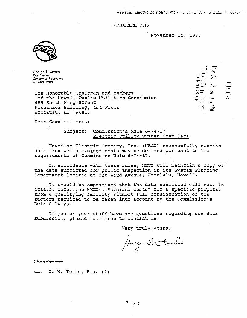
ATTACHMENT 7 .lA
November 25, 1988
Georce T. lwah1r0 VICe Fres1dent Consumer. Regulatory & Puoi1C Atta1rs
The Honorable Chairman and Members of the Hawaii Public Utilities Commission
465 South King Street Kekuanaoa Building, 1st Floor Honolulu, HI 96813
Dear Commissioners:
Subject: Commission's Rule 6-74-17 Elect~ic Utilitv Svstem Cost Data
-r. -· ·-· :::;:: --· -- -~-- ·-Cool~~ -c.r. ··--
== -· -· ; .._ - :
I
-c: o..-:: ,....,.; c.::·
r~,-~
' ----· -·c:.:-~
Hawaiian Electric Company, Inc. (HECO) respectfully submits data from which avoided costs may be derived pursuant to the requirements of Commission Rule 6-74-17.
In accordance with these rules, HECO will maintain a copy of· the data submitted for public inspection in its System Planning Department located at 820 Ward Avenue, Honolulu, Hawaii.
It should be emphasized that the data submitted will not, in itself, determine HECO's "avoided costs" for a specific proposal from a qualifying facility without full consideration of the factors required to be taken into account by the Commission's Rule 6-74-23.
If you or your staff have any questions regarding our data submission, please feel free to contact me.
Very truly yours,
Attachment
cc: C. W. Totto, Esq. (2)
7.1A-l
~~
! -... __
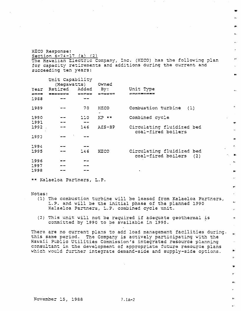
HECO Response: Sec-:ion 6-74-17 (a) (2) ~he Hawaiian Elec-:ric Company, Inc. (HECO) has the follo~ing plan :or capaci-:y re-:iremen-:s and additions during the curren-: and succeeding -:en years:
Unit Capabili":y (Megawa-:":s) Owned
Year Re":ired Added By: ==== ====== 1988
1989
1990 1991 1992
1994 1995
1996 1997 1998
===== ======
70 HECO
110 KP **
146 J-.. ES-BP
146 HECO
** Kalaeloa Partners, L.P.
Notes:
Uni't Type =========
Combustion turbine (1)
Combined cycle
Circula-:ing fluidized bed coal-fired boilers
Circulating fluidized bed coal-fired boilers (2)
(1) The combustion turbine will be leased from Kalaeloa Partners, L.P. and will be ':he ini-:ial phase of the planned 1990 Kalaeloa Par":ners, L.P. combined cycle unit.
(2) This unit will not be required if adequate geothe=rr.al is committed by 1990 to be available in 1995.
There are no current plans to add load management facilities during. ':his same period. The Company is ac-:ively participating with the Ha~aii Public Utili-:ies Commission's in-:egra-:ed resource planning consultan-: in the development of appropria-:e future resou;=e plans which would further integrate demand-side and supply-side op-:ions.
November 15, 1988 7 .lA-2
..
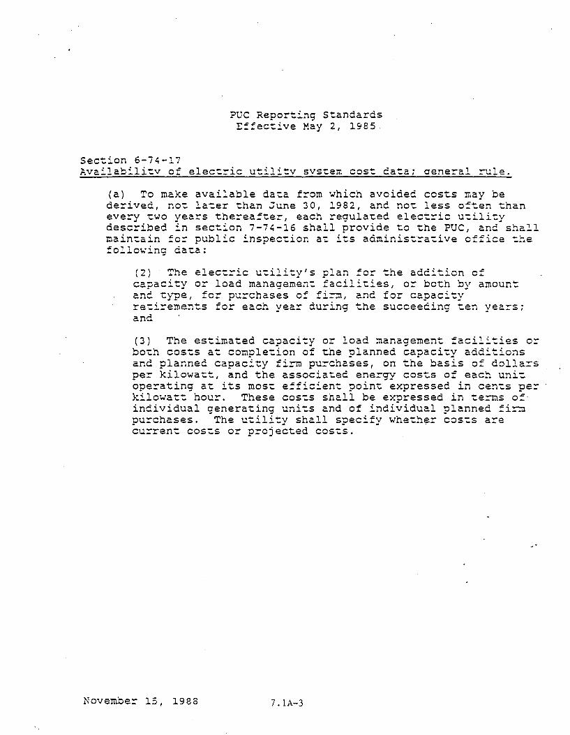
Sec~ion 6-74-17
PUC Reporting Standards Effec~ive May 2, 1985
Availabili~v of elec~ric utilitv svstern cost data~ aeneral r~le.
(a) To make available data from which avoided costs may be derived, no~ later than June 30, 1982, and not less often than every two years thereafter, each regulated elec~ric utility described in section 7-74-16 shall provide to the PUC, and shall main~ain for public inspection at its administra~ive office the follo~ing data;
(2) The electric utility's plan for the addition of capacity or load management facilities, or both by amount and type, for purchases of fi~, and for capacity retirements for each year during the succeeding ten years; and
(3) The estimated capacity or load management facilities or both costs at completion of the planned capaci~y additions and planned capacity firE purchases, on the basis of dollars per kilowatt, and the associated energy costs of each uni~ operating at its most efficient point expressed in cents per kilowatt hour. These costs shall be expressed in terms of individual generating units and of individual planned firm purchases. The utility shall specify wheth~r costs are current costs or projected costs.
November 15, 1988 7.1A-3
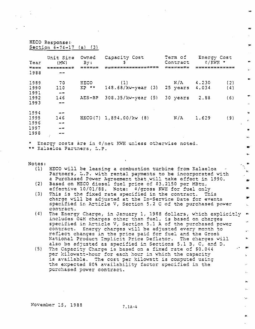
HECO Response:· Sec-tion 6-74-17 (a) ( 3)
Unit s~ .. ,.,. ..... _ Owned Capaci-ty Cost Te:=-m of Ene:=-cv -- Cost Yea:=- (mn By: $ Cont:=-ac": ¢/KWH * ==== ========= ====== =======~========= ======== ============= 1988
1989 70 HECO ( 1) N/A 4.230 ( 2) 1990 110 KP .... 148.68/kw-year ( 3) 25 years 4.034 ( 4) 1991 1992 146 AES-BP 308. 35/kY.•-year ( 5) 30 yea::s 2.88 ( 6) 1993
1994 1995 146 HEC0(7) 1,894.00/kw ( 8) N/A 1.629 ( 9) 1996 1997 1998
* Ene::gy costs are in ¢/net ~~H unless othe::wise ** Kalaeloa Pa::-tne::s, L.P.
noted.
Notes: ( 1)
( 2)
( 3)
( 4)
( s)
HECO will be leasing a combustion turbine from Kalaeloa Partners, L.P. with rental payments to be incorporated with a Purchased Power Agreemen~ that.will take effect in 1990. Based on HECO diesel fuel price of $3.2150 per MBtu, effec-tive 10/01/88. Note: ¢/gross KWH fo:=- fuel only This is the fixed rate specified in the contract. This charge will be adjusted at the In-Service Date for events specified in Article V, Sec~ion 5.2 C of the purchased power contract. The Energy Cha:=-ge, in January 1, 1988 dollars, which explicitly includes O&M charges other than :uel, is based on charges specified in Article v, Section 5.1 A of the purchased power con-t::act. Energy charges ~ill be adjusted every month to reflect changes in the p::ice paid for fuel and the Gross National Product Implicit P:=-ice Deflate::. ~he charges will also be adjusted as specified in Sections 5.1 3, C, and D. The Capaci-ty Charge is based on a fixed rate of $0.044 pe:: kilowatt-hour for each hour in which the capacity is available. The cos": pe:: kilowatt is computed using the expected 80% availability factor specified in the purchased powe:=- contract.
Novernbe:=- 15, 1988 7 .lA-4
II''
""
,.. .. "
"' ... ...
~
""
fjl
IlK
'Jill
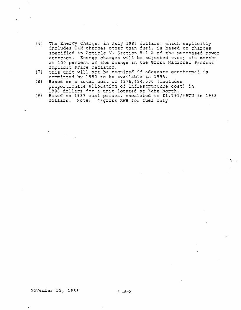
(6) The Energy Charge, in July 1987 dollars, which explicitly includes O&M charges other than fuel, is based on charges specified in Article V, Section 5.1 A of the purchased power contract. Energy charges will be adjusted every six months at 100 perce~t of the change in the Gross National Pr~cuct Im~lici~ P=ice De:la~o=.
(7) This unit will not be required if adequate geothe=rr.al is co~~itted bv 1990 to be available in 1995.
(8) Based on a total cost of $276,454,500 (includes proportionate allocation of infrastructure cost) in 1988 dollars for a unit located at Kahe North.
(9) Based on 1987 coal prices, escalated to $1.791/METU in 1988 dollars. Note: C/gross KWH for fuel only
Nove~~er 15, 1988 7.1A-5
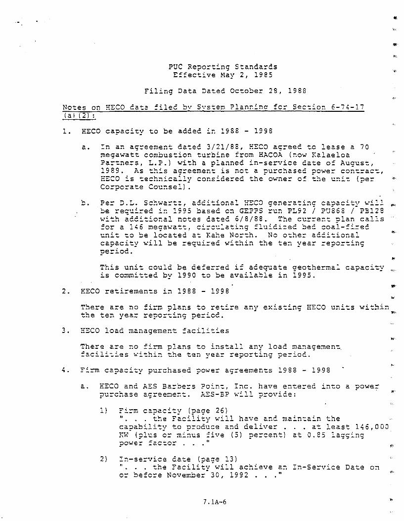
PUC Repo=ting Standards E!fective May 2, 1985
Filing Data Dated October 28, 1988
Notes on HECO data filed bv Svstem Planr.inc fc= Section 6-7~-17 (a) ( 2) :
1. EECO capacity to be added in 1988 - 1998
a.
b.
In an ag=eernent dated 3/21/88, HECO ag=eed to lease a 70 megawatt combustion turbine from HACOA (now Kalaeloa Partners, L.P.) with a planned in-service date of August, 1989. As this agreement is net a purchased powe= contrac~, EECO is technically considered the owner of the unit (per Corporate Counsel) .
Per D.~. Schwa=tz, additional HECO generating capacity w~,, be required in 1995 based on GEPPS run PL92 I PU868 I ?Bl28 with additional notes dated 6/8/88. The current plan calls for a 146 rnega~att, circulating fluidized bed coal-fired unit to be located at Kahe North. No other additional capacity ~ill be required within the ten year =eporting period.
This unit could be defer=ed if adequate geothermal capacity is committed by 1990 to be available in 1995.
2. HECO retirements in 1988 - 1998
There are no firm plans to retire the ten year reporting period.
3. HECO load management facilities
any existing HECO units
There are no fi=m plans to install any load management facili~ies ~ithin the ten year reporting period.
4. Firm capacity purchased power agreements 1988 - 1998
within
a. EECO and AES Barbers Point, Inc. have entered into a power purchase agreement. AES-BP ~ill provide:
l) Firm capacity (page 26) 11
• the Facility will have and maintain the capability to produce and deliver . at least 146,000 KW (plus cr minus five (5) percent) at 0.85 lagging power factor . II
2) !r.-service aate (page 13) 11
• the Facility will achieve an In-Service Date on or befo:=-e Noverr..ber 30, 1992 . "
7 .lA-6
'll!i'·
/111!'
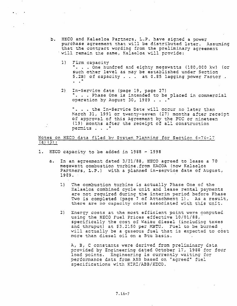
b. HECO and Kalaeloa Pa~tne~s, L.P. have signed a powe~ pu~chase ag~eement that will be dist~ibuted late~. Ass~~ing that the cont~act wording £~om the prelimina~y ag~eement .._.ill remain the satne, Kalaeloa .._•ill provide:
1) Fi=m capacity " . One hund~ed and eighty megawatts (180,000 kw) (o~ such other level as may be established under Section 5.2B) of capacity . . . at 0.85 lagging powe~ Factor .
II
2) In-Service ca te (page 19 I page 2 7) " . Phase One is intended to be placed in com.mercial operation by August 30, 1989 . 11
11- •• the !n-Se~vice Date will occur no late~ than
March 31, 1991 or twenty-seven (27) months a£ter receipt of approval of this Agreement by the PUC or ninetee~ (19) months after the receipt of all construction
II
Notes on HECO data filed bv Svstem Planninc for Section 6-74-17 ( al ( 3 l :
1. EECO capacity to be added in 1988 - 1998
a. In an agreement dated 3/21/88, EECO agreed to lease a 70 megawatt combustion turbine.from EACOA (now Kalaeloa Partners, L.P.) with a planned in-service date of August, 1989 ..
1) ~he combustion turbine is actually Phase One o£ the Kalaeloa combined cycle unit and lease rental payments are not required during the inte:::-im pe:::-iod befo:·e Phase Two is completed (page 7 o£ Attachment 1). As a result 1
there are no capacity costs associated with this unit.
2) Energy costs at the most efficient point were ~omputed using the EECO Fuel P:::-ices effective 10/01/88, specifically the cost of Waiau diesel (including taxes and th:::-uput) at $3.2150 pe:::- M3~U. Fuel to be burned will actually be a gaseous fuel that is expected to cost more than diesel oil on a Btu basis.
A, 3, C constants were de:::-ived from p:::-eliminary cata p:::-ovided by Engineering cated October 17, 1988 for four load points. Engineering is cu:::-rently waiting for pe:::-fo=mance data from !>.33 based on "agreed 11 fuel specifications with F.IR:/A33/F.ECO.
7. lA-7
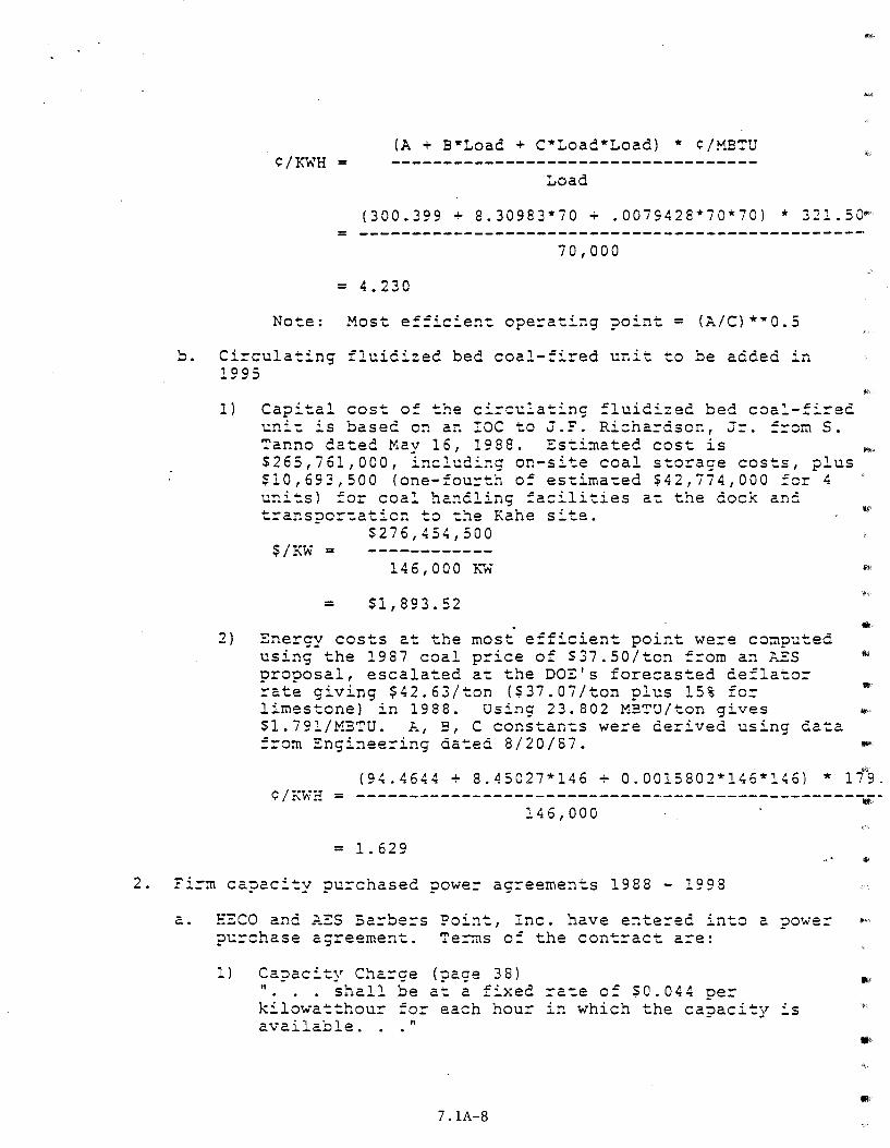
{A + B*Load + C*Load*Load) * ¢/MBTU ¢/KWH =
Load
{300.399 ~ 8.30983*70 + .0079428*70*70) * 321.50•
= ------------------------------------------------70,000
= 4.230
No~e: Most efficien~ operating point= {A/C)*~o.s
Circulating fluidized bed coal-fired unit to be added in 1995
1}
2)
Capi~al cos~ of the circulating fluidized bed coal-fired uni~ is based on an !OCto J.F. Richa=dson, J=. ==omS. Tanno dated May 16, 1988. Es~imated cost is $265,761,000, including on-site coal storage cos~s, plus Sl0,693,500 (one-four~h of estima~ed $42,774,000 fer 4 u~its) for coal handling facilities a~ the dock and transpor~ation to the Kahe site.
$276,454,500 $/~w =
146,000 ~w
= $1,893.52
Energy costs at the most efficien~ point we~e compu~ed using the 1987 coal price of S37.50/ton from an AES proposal, escalated at the DOE's forecas~ed deflator rate giving $42.63/ton ($37.07/ton plus 15% for limestone) in 1988. Using 23.802 METU/ton gives Sl.791/METU. A, B, C constants were derived using data from Engineering dated 8/20/87.
•
•
~
(94.4644 + 8.45027*146 + 0.0015802*146*146) * 179. ¢/KWH = ------------------------------------------------.-
146,000
= 1.629 •
2. Firm capacity purchased power agreements 1988 - 1998
a. EECO and AES 5arbers purchase agreement.
Point, Inc. have e~tered in~o Te=rns of the contract are:
1) Capaci~y Charge {page 38) " . shall be at a fixed rate of $0.044 per
a power
kilowatthour for each hour in which the capacity is available. "
7.1A-8
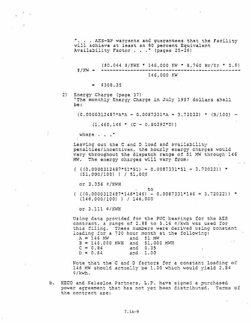
" ... AES-BP wa~rants and guarantees that the Facility will achieve at least an 80 pe~cent Equivalent Availability Facto~ ... " (pages 25-26)
($0.044 S/KWH * 146,000 KW * 8,760 Hr/Yr * 0.8) $/~w = -----------------------------------------------
146,000 K~
= $308.35
2) Ene~gy Cha~ge (page 37) "The monthly Ene~gy Cha~ge in July 1987 dolla=s shall be:
(0.0000312487*A*A- 0.008733l*A + 3.72022) * (B/100) -
(1,460,146 * (C- 0.80292*D))
where II
Leavi~g out the C and D load and availability penalties/incentives, the hou~ly ene~gy cha~ges would va~y th~oughout the dispatch range of 51 MW through 146 MW. The energy charges will vary f~om:
((0.0000312487*51*51) - 0.0087331*51 + 3.72022)) * (51,000/100) l I 51,0~0
or 3.356 ¢/KWH to
( (0.0000312487*146*146) - 0.0087331*146 + 3. 72022)) * (146,000/1001 l I 146,000
or 3.111 ¢/KWH
Using data provided for the PUC hea~ings for the AES contract, a range of 2.88 to 5.16 ¢/kwh was used fo~ this filing. These n~~e~s were derived using constant loading for a 720 hour month at the following:
A = 146 M\\1 and 51 MW B = 14 6 , 0 0 0 !-H\H and 51 , 0 0 0 MWrl C = 0.84 and 0.35 D = 0.84 a~d 1.00
Note that the C and D factors fo~ a constant loading of 146 MW should actually be 1.00 which would yield 2.84 ¢/kwh.
b. F.ECO and Kalaeloa Partners, L.P. have signed a purchased power agreement that has not yet been distributed. Te~s of the contract are:
7.1A-9
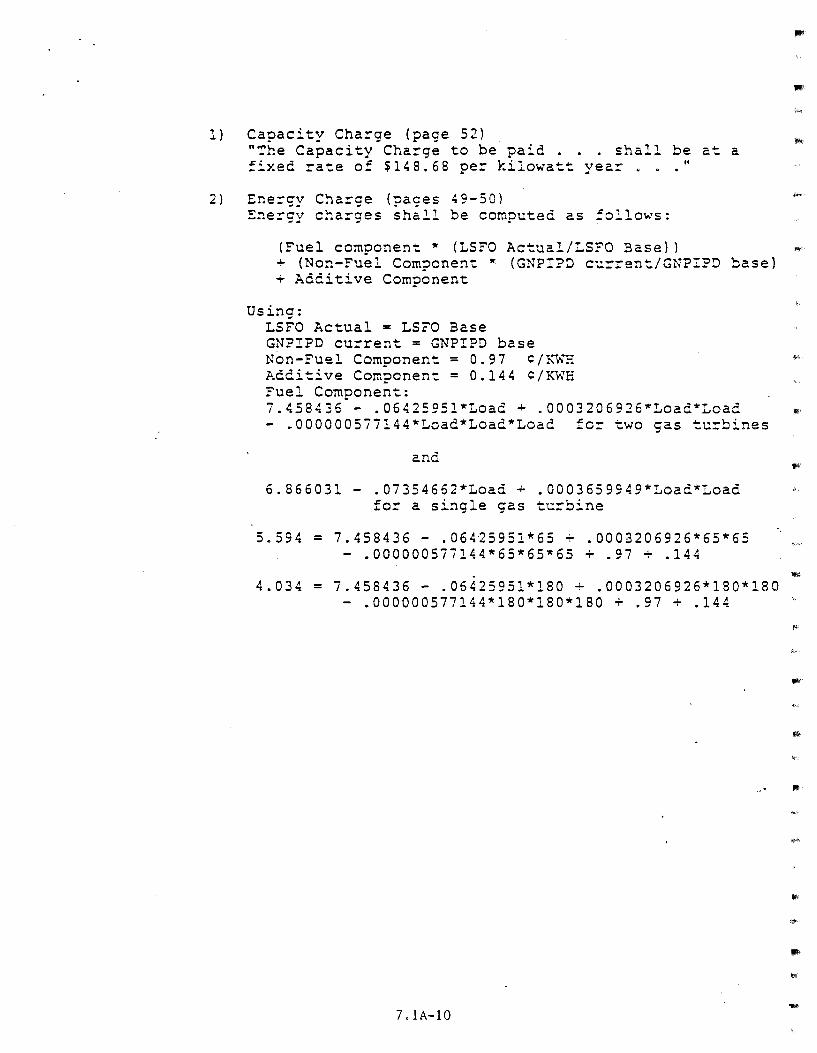
1) Capacity Charge (page 52) "~he Capacity Charge to be paid . . . shall be at a fixed rate of $1,8.68 per kilowatt year ... "
2) Energy Charge (pages 49-50) Energy charges shall be computed as follows:
(Fuel component • (LSFO Actual/LSFO Base)) ~ + (Non-Fuel Component * (GNPIPD current/GNP!PD base] + Additive Component
Using: LSFO Actual = LSFO Base GNP!PD current = GNPIPD base Non-Fuel Component= 0.97 ¢/~1NH
Additive Component = 0.144 ¢/KWH Fuel Component: 7.458436 - .0642595l*Load + .0003206926*Load*Load - .000000577144*Load*Load*Load for two gas turbines
and
•
6.866031- .07354662*Load + .0003659949*Loac*Load ~ for a single gas turbine
5.594 = 7.458436 - .06425951*65 + .0003206926*65*65 - .000000577144*65*65*65 + .97 + .144
. 4.034 = 7.458436 - .06425951*180 + .0003206926*180*180
- .000000577144*180*180*180 + .97 + .144
7.1A-10
•
APR - 3 ~::9
March 31, 1989
John F. Richardson, Jr., P.E. Executive Staff Engineer Hawaiian Electric Company, Inc. P.O. Box 2750 Honolulu, HI 96840-0001
ATTACHMENT 7 .lB
VIA EXPRESS MAIL
RE: HA WAIT GEOTHERMAL/INTERISlAND TRANSMISSION PROJECf RFP SOLICITATION
Dear Mr. Richardson:
I am sure you are familiar with the progress the Puna Geothermal Venture (PGV) has recently been making in the development of the first commercially operated geothermal project on the Big Island of Hawaii. Such progress has accelerated since Ormat Energy Systems, Inc. acquired the rights to develop the project.
The level of our investment demonstrates that we at Ormat are unequivocally committed to participating in any future development of the geothermal potential in the State of Hawaii. To that end, we have been approached by potential participants, very prominent companies which are certainly capable of providing the supplementary technology associated with the cable and the transmission lines, as well as the financial resources required to carry the project forward ..
Consequently, and in view of the fact that the decision on the short list of bidders will be pending for some time, Ormat ha,s proposed to all potential bidding groups that we will be standing by to provide the geothermal resource and the Ormat technology to the extent feasible. In the meantime, we will continue to concentrate on the development of the first phase and to monitor the 500 MW process.
In any event, please find enclosed our Qualifications and Experience document, which will provide you with background information on Ormat, as well as copies of our letter to the potential bidders.
Best regards,
~/i#lf &~~ic{~tf . .;
HR/lks
Enclosure
35528M
ORMAT ENERGY SYSTEMS, INC. 610 East Glendale Ave., Sparks, Nevada 89431-5811 • Telephone (702) 356-9111 • Facsimile (702) 356-9125 • Telex 170030
ATTACHMENT 7.1C
MID-PACIFIC GEOTHERMAL, INC. Exploration Development Marketing of Geothermal Resources
April 3, 1989 APR 4 1939
Mr. John F. Richardson, Jr., P.E. Executive Staff Engineer Hawaiian Electric Company, Inc. P.O. Box 2750 Honolulu, Hawaii 96840
SUBJECT: Hawaii Geothermal/Interisland Transmission Project RFP Solicitation
Dear Mr. Richardson,
True Geothermal Energy Company and Mid-Pacific Geothermal, Inc., are interested in and expect to participate in, arriving at a contract with Hawaiian Electric Company to supply 500mw of geothermal electrical power from the Kilauea east rift zone for transmission to Oahu via a proposed HVDC transmission system. We have had discussions with two major corporations with the capability to organize and finance the generating and transmission components of-the subject project.
Due to the limited time in which to respond to HEco•s solicitation of interest letter of February 10, 1989, it was not possible to identify or commit to any particular organization or lead entity that would ultimately respond to the RFP. However, we had no objection to any respondent identifying True/MidPacific as a resource producer who would cooperate in efforts leading towards development of the project, subject of course to reaching a business agreement among the participating parties. Therefore, it is possible that True/Mid-Pacific may be identified as a resource/energy producer in the organization description of more than one RFP respondent.
As to our capability to explore for and develop geothermal resources, that portion of the Kilauea east rift zone within the land surface area under lease by True/Mid-Pacific from the Estate of James Campbell (27,000 acres more or less) has been grossly estimated to have a geothermal resource potential sufficient to supply up to 400mw of electrical power. We currently have a land use permit to develop up to 100mw of power within the State mining lease area and geothermal resource subzone consisting of about 9,000 acres of the Campbell Estate property.
We foresee our participation in the project within an organizational structure that may be formed as follows:
ADMINISTRATIVE OFFICES Suite 823 • Interstate Bank Building • P.O. Drawer 3454 • Casper, Wyoming 82602 • Telephone (307) 234-7386 OPERATIONS OFFICE: Pioneer Plaza, Suite 1777 • 900 Fort Street Mall • Honolulu, Hawaii 96813 • Telephone (808) 521-9004
ATTACHMENT 7.1C (continued)
Major Geothermal Resouce Producer - True/Mid-Pacific
Power Generating Systems -True/Mid-Pacific, Campbell • Estate (at their option), and others, such as a major power plant vendor.
HVDC Transmission Systems - A major cable manufacturer; participants to be determined)
Lead Entity for Proposal including financing of generating and transmission systems - (To be determined).
In the interim, we are continuing to investigate evolving technology in geothermal resource development and power generating/transmission systems to enhance the prospects of producing and transmitting geothermal generated electricity within cost ranges that will encourage wide private sector interest and participation in this project.
We are hopeful of initiating our exploration effort by the 4th quarter of this year, subject to obtaining administrative approval of remaining documents/permits required for conducting geothermal exploration activities in the Kilauea middle east rift zone.
cc: Estate of James Campbell ASEA Brown Boveri
Very truly yours,
Mitsubishi Heavy Industries, Ltd. Toyo Menka Kaisha, Ltd.
-2-
co.
~·
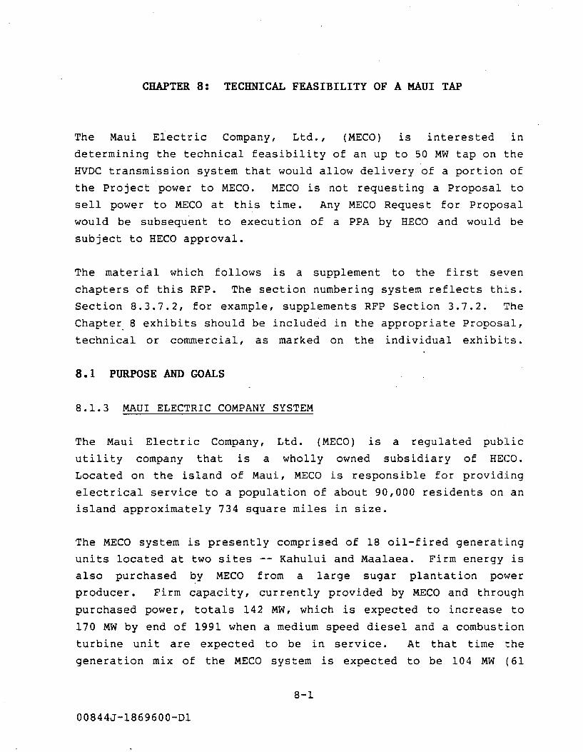
CHAPTER 8: TECHNICAL FEASIBILITY OF A MAUl TAP
The Maui Electric Company, Ltd., ( MECO) is in teres ted in
determining the technical feasibility of an up to 50 MW tap on the
HVDC transmission system that would allow delivery of a portion of
the Project power to MECO. MECO is not requesting a Proposal to
sell power to MECO at this time. Any MECO Request for Proposal
would be subsequent to execution of a PPA by HECO and would be
subject to HECO approval.
The material which follows is a supplement to the first seven
chapters of this RFP. The section numbering system reflects this.
Section 8.3.7.2, for example, supplements RFP Section 3.7.2. The
Chapter. 8 exhibits should be included in the appropriate Proposal,
technical or commercial, as marked on the individual exhibi l:s.
8.1 PURPOSE AND GOALS
8.1.3 MAUI ELECTRIC COMPANY SYSTEM
The Maui Electric Company,
utility company that is a
Ltd. (MECO) is a regulated public
wholly owned subsidiary of HECO.
Located on the island of Maui, MECO is responsible for providing
electrical service to a population of about 90,000 residents on an
island approximately 734 square miles in size.
The MECO system is presently comprised of 18 oil-fired generating
units located at two sites -- Kahului and Maalaea. Firm energy is
also purchased by MECO from a large sugar plantation power
producer. Firm capacity, currently provided by MECO and through
purchased power, totals 142 MW, which is expected to increase to
170 MW by end of 1991 when a medium speed diesel and a combustion
turbine unit are expected to be in service. At that time the
generation mix of the MECO system is expected to be 104 MW ( 61
8-1
00844J-1869600-Dl
percent) base load, 37 MW ( 22 percent) cycling and 29 MW ( 17
percent) peaking.
MECO recorded a peak demand of 124.7 MW in December, 1988 and
produced a total of 651,717,860 gross kilowatt-hours in 1988.
Purchased power for the same period was 94,106,156 kilowatt-hours.
System load factors range from 67 percent to 69 percent on a
yearly basis.
8.1.4 NATURE OF POWER REQUIREMENTS
With the improved economic climate of the mid-1980's MECO has seen
a corresponding increase in peak load. While the growth rate has
not returned to the levels seen before the oi 1 crisis of the
1970's, growth is strong and is expected to continue at a moderate
three percent rate.
It is estimated that MECO could purchase up to 50 MW of Project
power in 1995. .HECO will have first right to power produced by
the Project. Any PPA with MECO will be subsequent to successful
execution of a PPA by HECO.
8.3 TECHNICAL INFORMATION
8.3.6 HVDC TRANSMISSION SYSTEM
The PROPOSER is requested to determine the technical feasibility ~
of an up to 50 MW tap on Maui. The Proposal should contain a
discussion of the feasibility of such a tap. This discussion
should specifically include the impact such a tap would have on
the overall Project HVDC control system, both with regard to any
required hardware modifications and any modifications to operating
procedures. It is possible that maintaining the stability of the
HVDC system to Oahu could result in relatively undesireable
8-2
00844J-1869600-Dl
performance character is tics of the Maui converter terminal. If
so, these should be discussed.
Figure 8.3A is a schematic representation of the geothermal power
transmission system including a tap on Maui.
8.3.6.2 Converter Locations
A Maui converter terminal would logically be located along the
southern shore line near the designated GRS on Maui (see Figure
3.6B). This location would provide easy access to a 69 or 138kV
AC transmission line connected to the MECO system if geothermal
development on Maui occurs. Such a location would be sui table
whether the Maui termination was in-and-out or the DC transmission
crossed Maui overland.
8.3.6.4 Converter Terminals
The Maui converter can be either bipolar or monopolar. The latter
is probably appropriate in order to lessen the effect of
disturbances in the Maui converter or MECO AC system on the HECO
converter performance. The Maui converter will operate as an
inverter. Power transfer will be from Hawaii to Maui.
Possible operating modes for the HVDC system that includes a Maui
tap are:
• Monopolar metallic return - Maui tap only
8.3.6.7 HVDC Neutral Grounding System
The Maui pole current will only be about 80 amperes and this may
be allowable as an unbalance on the Puna-Waimanalo line without
the addition of a ground return at Maui.
8-3
00844J-1869600-Dl
It is possible that because of its low cur rent requirement, a
ground electrode can be used on Maui if a ground return is needed.
8.3.7 EXISTING AC SYSTEM CHARACTERISTICS
8.3.7.2 Electrical and System Data
System Operating Parameters
a. Voltage - kV (deviation)
- Nominal phase-to-phase - Normal minimum phase-to-phase - Normal maximum phase-to-phase - Emergency minimum phase-to-phase - Emergency maximum phase-to-phase - Normal negative sequence - Maximum phase unbalance
b. Frequency - Hz (deviation limit)
- Normal base - Normal minimum - Normal maximum - Emergency minimum - Emergency maximum
c. Load Shedding
Minimum frequency - unknown
Blk
1 2 3 4 5 6
Freg (Hz)
59.3 59.2 59.1 58.7 58.5 58.0
Time (s)
10 10
d. Load Restoration Schedule
MVA (day)
MECO
69 66 73 63.2 73 Unknown Unknown
MECO
60 59.95 60.05 58.5 (lOs) 61.5 (20s)
MVA (eve)
3.5 8.5 3.5 5.5
10.5 11.0
There is no set schedule on Maui for load pick-up. Manual
reclosure is accomplished through SCADA with the lowest
operating level at 59.7 Hz.
8-4
00844J-1869600-Dl
e. Approximate Short Circuit Capability
At Maalaea Substation bus (1989) at 69 kV.
Three phase fault Maximum 6 ". 6 kA
Minimum 2.3 kA
Single phase-to-ground Maximum 7.8 kA
fault Minimum 3.1 kA
f. 1994 System Impedance
(per unit on 10 MVA base)
Positive Sequence Zl Maximum generation: .00139 + j.Ol27 Minimum generation: .00247 + j.0373
Zero Sequence ZO Maximum generation: .00083 + j.0067 Minimum generation: .00082 + j.0068
See Figure 8.3B for impedance branch data.
g. Load Flow Diagrams
Load flow data for the MECO system at peak, minimum and
average load are given in Figures 8.3C, 8.3D, and 8.3E
respectively.
h. One Line Diagram
The one line diagram for the MECO system is shown on
Figure 8.3F.
8-5
00844J-1869600-Dl
•
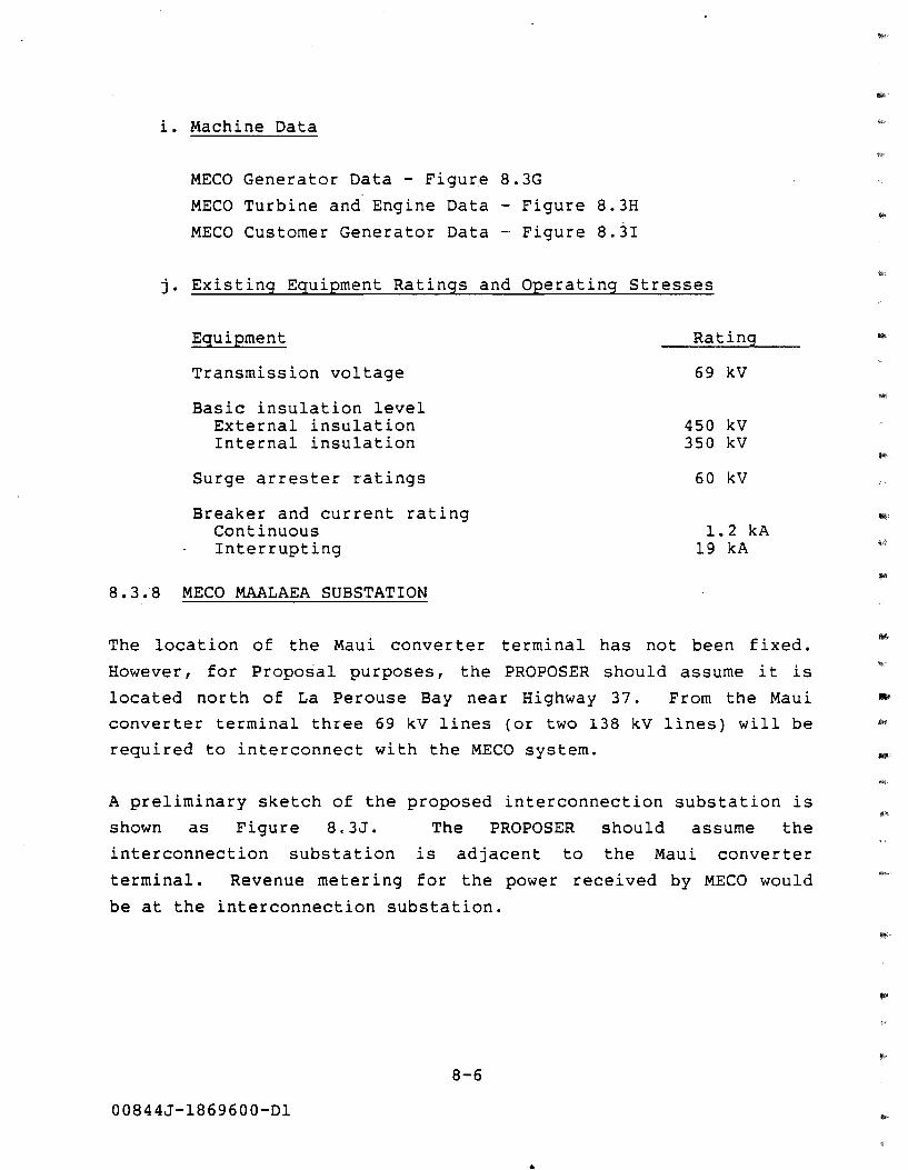
i. Machine Data
MECO Generator Data - Figure 8.3G
MECO Turbine and Engine Data - Figure 8.3H
MECO Customer Generator Data - Figure 8.3I
j. Existing Equipment Ratings and Operating Stresses
Equipment
Transmission voltage
Basic insulation level External insulation Internal insulation
Surge arrester ratings
Breaker and current rating Continuous Interrupting
8.3.8 MECO MAALAEA SUBSTATION
Rating
69 kV
450 kV 350 kV
60 kV
1.2 kA 19 kA
The location of the Maui converter terminal has not been fixed.
However, for Proposal purposes, the PROPOSER should assume it is
located north of La Perouse Bay near Highway 37. From the Maui
converter terminal three 69 kV lines (or two 138 kV lines) will be
required to interconnect with the MECO system.
A preliminary sketch of the proposed interconnection substation is
shown as Figure 8. 3J. The PROPOSER should assume the
interconnection substation is adjacent to the Maui converter
terminal. Revenue metering for the power received by MECO would
be at the interconnection substation.
8-6
00844J-1869600-Dl
..
8.4 RELIABILITY
Inclusion of a Maui tap may degrade the overall reliability of
Project power deliveries to Oahu. The PROPOSER should provide a
reliability assessment for Cases 1 and 2 of Section 4.5 with the
Maui tap. The equivalent Chapter 4 exhibits request a reliability
assessment that excludes the possible Maui tap.
Exhibit 8. 4A requests a comparison of the estimated reliability
for these two cases with and without the tap. Exhibits 8.4B and C
request the supporting reliability documentation for Cases 1 and
2, respectively.
8.5 POWER DELIVERY AND SCHEDULE
MECO is not seeking proposals at this time for power from the
Project. However, if a tap on Maui is technically feasible, MECO
could at some time in the future solicit up to 50 MW of Project
power. At the present time this is envisaged as baseload power.
However, if the Project power can be cycled, MECO may elect to
solicit proposals for cyclable power also.
8.7.1 FINANCIAL PROJECTIONS
8.7.1.1 Avoided Costs
MECO's latest avoided cost filing is included here as Attachment
8.7A.
8-7
00844J-1869600-Dl
8.7.1.6 Potential Price for Power
Section 7.1 requests cost information for the first phase and the
complete Project without a Maui tap.
If the Maui tap is technically feasible, the PROPOSER should
provide comparable information for a system that includes a
possible Maui tap. Exhibit 8.7A requests summary level costs for
the Maui tap secparately and the additional costs that would be
incurred to modify the base Project to accept the tap. Separate
Exhibits 8.7B, C and D should be provided for the first phase and
the complete Project to support Exhibit 8. 7A. Exhibits 8.7B, C
and D do not need to differentiate between the direct Maui costs
and the cost of modifications to the base Project.
8.8 REFERENCES FOR CHAPTER 8
1.
2.
Mountford, J.D. System Studies (4 volumes). Power Technolo
gies, Inc. 1984
Mountford, J.D. HDWC Phase II-C System Studies. Power
Technologies, Inc. 1987.
8-8
00844J-1869600-Dl
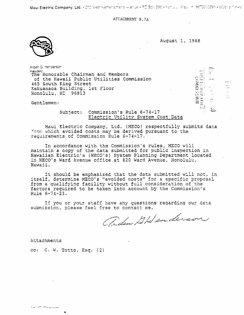
ATTACHMENT 8.7A
August 1, 1988
Araen G 1-lerl:Jerson Fres1oer;; The Honorable Chairman and Members of the Hawaii Public Utilities Commission
465 South King Street Kekuanaoa Building, 1st Floor Honolulu, HI 96813
Gentlemen:
Subject: Commission's Rule 6-74-17 Electric Utilitv svstem Cost Data
r:-.. : ..... i
- ·--· 3:?"
(l" -=·:
... , ,,,,
Maui Electric Company, Ltd. (MECO) respectfully submits da~a ~rorr which avoided costs may be derived pursuant to the requirements of Commission Rule 6-74-17.
In accordance with the Commission's rules, MECO will maintain a copy of the data submitted for public inspection in Hawaiian Electric's (HECO's) System Planning Department located in HECO's Ward Avenue office ~t 820 Ward Avenue, Honolulu, Hawaii.
It should be emphasized that the data submitted will not, in itself, determine MECO's "avoided costs" for a specific pr-oposal from a qualifying facility without full consideration of the factors required to be taken into account by the Commiss~on's Rule 6-74-23.
If you or your staff have any questions regarding our data submission, please feel free to contact me.
Attachments
cc: C. W. Totto, Esq. (2)
~ - ' ,-' ,.... -- ·-- -· . •
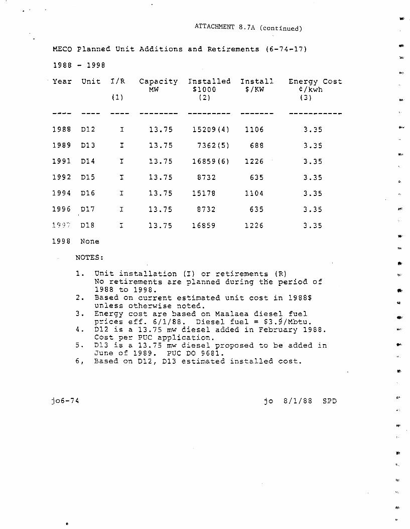
ATTACID1ENT 8. 7 A (continued)
MECO Planned Unit Additions and Retirements (6-74-17)
1988 - 1998
Year Unit I/R
1988 D12 I
1989 D13 I
1991 D14 I
1992 D15 I
1994 D16 I
1996 D17 I
19')/' D18 I
1998 None
NOTES:
Capacity MW
13.75
13.75
13.75
13.75
13.75
13.75
13.75
Installed $1000
( 2)
15209 (4)
7362(5)
16859(6)
8732
15178
8732
16859
Install $/KW
1106
688
1226
635
1104
635
1226
Energy Cost ¢/kwh ( 3)
3.35
3.35
3.35
3.35
3.35
3.35
3.35
1. Unit installation (I) or retirements (R) No retirements are planned during the period of 1988 to 1998.
2. Based on current estimated unit cost in 1988$ unless otherwise noted.
3. Energy cost are based on Maalaea diesel fuel prices eff. 6/1/88. Diesel fuel = $3.~/Mbtu.
4. D12 is a 13.75 rnw diesel added in February 1988. Cost per PUC application.
5. D13 is a 13.75 mw diesel proposed to be added in June of 1989. PUC DO 9681.
6, Based on D12, Dl3 estimated installed cost.
jo6-74 jo 8/1/88 SPD
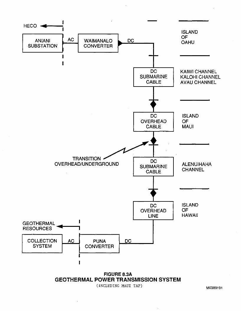
HECO .... ~-----
AN IAN I AC WAIMANALO ..... DC SUBSTATION CONVERTER
,....
I I
TRANSITION OVERHEAD/UNDERGROUND
GEOTHERMAL ~ I RESOURCES I
COLLECTION AC PUNA DC SYSTEM CONVERTER
FIGURE 8.3A
-1-
DC SUBMARINE
CABLE
~ ~
~
DC OVERHEAD
CABLE
j ~
DC SUBMARINE
CABLE
l ~ ~ DC
OVERHEAD LINE
ISLAND OF OAHU
KAIWI CHANNEL KALOHICHANNEL AVAU CHANNEL
ISLAND OF MAUl
ALENUIHAHA CHANNEL
ISLAND OF HAWAII
GEOTHERMAL POWER TRANSMISSION SYSTEM (INCLUDING MAUl TAP)
M0389191
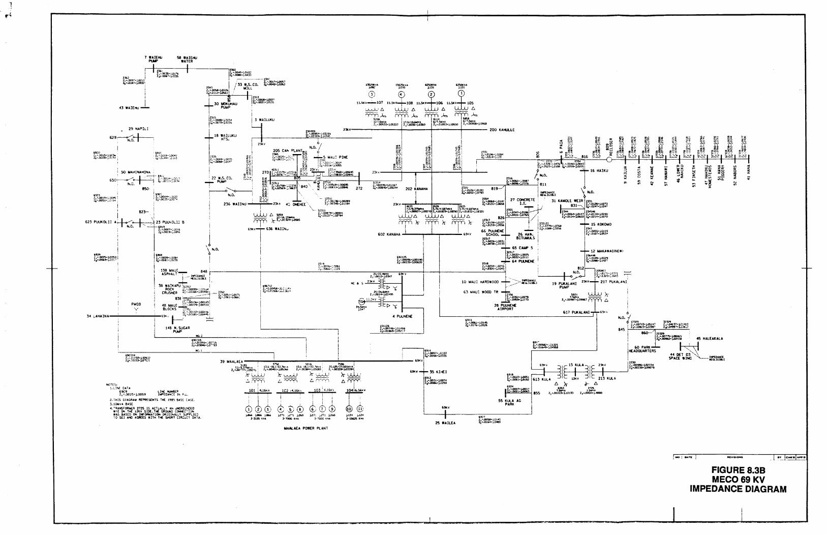
n:"
I i
I 43 WAIEHU-
29 'IAPILI
629~--·t-~ N.D.
:, ~ . .)OtS• j.OOlb Zo•.OoJ1!1•J-~1~ ..
623 PUUKOLI l
50 IIAt<!>iA~INA
8~
l,tl: ~ h~~,.;:t~?:
I .~. .-N.C.
an-1
,! I '- --~ 23 PUUWUl B ---6911
PIICO y
["""~""
UO:'~
'22 w.s. co. -T- PuuP
~~
;
J \ N.O.
I
z, • .o:~~·~.o2 .. l~ 2{'•.03()46.•).4) .. .,.13
...O!£S: l.UM DAH
£9C9 Z 1 =.0025• j.OOS9
liNt: NUUB£R lWPEOA"'CE Ill. F.:...
2. 1"H;S OUGRAll REPRf.SOITS THE. J98S BAS£ CASE. 3.10WYA BAS(
41. '!~ANSrOR:t.AER 2725 IS AC"l'L:A;.i. Y Ah I.INCR~~~,iD£0 wv£ ~ 1HE 1ZlV SIDE. THE CROUND CONNEC"'"! ON
NC.l
wAS &AS£0 ON lJrEORII&AllOfll ORICI .. Ali.Y SlJPPLIEU 10 S£1 ANO &CREES allt1 THE. SHOAl C1R:J!1 0A1A.
W.AUEA POWER PLANT
~.~ .....
"'"" rJI ~)
11.51\"W'-· -107
~ PUUNENE
l0112i Zt•.OOl'Ctl•l-014~9 z0~.o1~9 .. J.osc: 1
112'0 z, ~.012t.• ).01!3 zo•.o202· J.o193
200 KAHUI.U I
! ~!. ~; a:
~ w
"" tt "'"' .. oo
... ... ~~ ~~~ "'G "' w 0
-~-=~- 816 s.:~ a: ... ' -13:!2- 1ll4 l, .. cm-;."'" , •. oo.o'j"'>o<l ~~-~3 .. j.2108 l0=-00S9• .Ol05
16 HAIKU 1<.0.
9 811
819
27 CONCRETE I.I.
.. ,. zl"'·~·.;.cu~ zo .. _ou .... ..-lbltSI
15 KOKOIIO
12 W.UWAO!NEWJ ,,.. ... ~=~=:tfm
617 PUKALANI
1r:1~·@,~ I KULA
); ~ 6 USl l72S
l.SW'VA t.Sti\'A z1 ~.otot:S•J-.10133 z1 ... 0400+J-4000
~~
... ~ .., ;;
~ "" Ill z .. 0 ; z
~ u .. :r
"' "' ~ ... "' "'
i I i 60 PARK I HEADQUARTERS
r
Zt..0091i .. J.()1034 I""' 10 •.022]()+ J.OtOTt
a:::>
'"'"' ·-o:z: .... ~ ~
~ "'"' .. ,..
"' ..
><0 za: ~
z _.,. ... .., .. "' "'"' :Z:C> "' ::: ~ .. ... -~ ..
Z>ll z -:; ~ w 1110. ... ,.
"' .., ... ~ "' "'
FIGURE 8.38 MEC069 KV
IMPEDANCE DIAGRAM
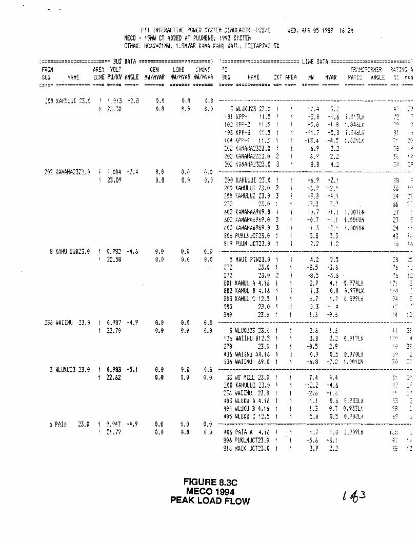
F'TI INTERACTIVE POWER SYSTEil JIMULATCR--PSS/E WED, AF·F: ~5 !999 16 24 i!ECO - f'SMW CT ADDED AT PUUNENE; !993 SYSTEM CTilAX: HC.~S=21MW; 1.8nVAF: K.~NA KAH!J ~AIL TIETAF'S=2.5%
:======================== BUS DATA =========================> !=========================== LINE DATA ============================· FF:Oii ARE~ VOLT Gal LOAD s:HUNT TO TPA?·t~::-OF~M~F~ ~:AT I :~G .; BlS ~{Af!E ZONE PU/KV ANGLE MW/HVAR ~W/MVAR ~W/MVAR 3!JS :KT AREA :iW MVAR RATIQ AiiGLE ;: ~VA
===== ============ ==== ===== =====
2~8 KAH~L~I 23.0 ; .'113 -2.8
282 KANAHA2323. 0 i l. 084 -3. 4 23.09
8 KAHU SUB23.9
236 ~AIINU 23.9
3 WLUKU23 23.0
6 PAIA 23.0
0.982 -4.6 22.58
0."187 -4.9 22 .. 7~
9.983 -5.1 22.62
f),947 -4.9 21.79
9.8 0.0
e.e
o.a 0.9'
======= ======= ===== ============ === ==== ====== ====== ======= ======= ==~ ====
e.e e.e
0.0 0.0
a~a ------··-------------------------------------------------··-··---------3 WLUKU23 23. ·)
i ~~ KPP-! ! 1.5 t02 {PP-2 t1 .5 ! '93 KPP-3 tl .5 104 KP~-4 tl .5 292 KANAHA2323.8 202 KANAHA2323, El 2 292 K~NAHP2323.0 3
'2.4 -5.0
-I L 7 -!3.4
6.9 L 0 :.;~,.
8.8
-1.6 L':H5LK -i , :3 t • t)4.~Lf
-5.3 i. ~46LK -4,5 ! .-~21Li<
'l '1 .:..~
2.2 4 )
(~' 0 ---------------------------------------------------------------------·-200 KAHULUI 23.9 200 KAHULUI 23.0 2 200 KAHULUI 23.v 3 . .,,.-, .s:,.;_
602 KANAHA6969.0 ~02 KANAHA6969.0 2 M!2 ~ANAHI\6969. 0 3 306 F'IJKL~.JCT23. 0 819 PUUN JCT23.0
-6.? _., ' ~ .. ;
-,~.'?
-a.a -4.1 i., 1 i ., i I&",.;
-0.7 -L t UOiUl -0.7 -1.1 I .901UN -'.3 -2.' i.901UN
2.2 L2
66 c J
27 . .,.., :-LI
24 43 i '~
i 6 . ,::,
e.~ -------------------------------------------------------------------·-9.9 5 !'IAUI PIN23.0
272 23.0 272 23.0 2 801 KAHUL A 4.16 802 KAHUL B 4.16 803 KAHUL S i2.5 l 895 23.9 840 23.El ~
4 ·J
-8.5 '1 " ... .J
-3.6 -8.5 -3.6 2.9 4.1 0.974LK 1.3 9.9 ~.979LK 6.7 1.7 0.399LK 1.3 _, ,4
j.,~ -9.6
:s
:....;
! ~t '!:
94
-,;;:
·~
. -,
e.e --------------------------------------------------------------------3 WU!KU23 23. 0
!J6 WAIINU 912.5 270 23.0 436 WAIINU A4.16 HS WAIINU 69.0
3.8 2.2 9.9F'LK
0.9 9.5 a.979LK -6.8 -7.2 1.21e1UN
i i.
a.e --------------------------------------------------------------------0.0 33 ~S 1ILL 23.0 1
209 KAHULUI 23.9 236 ~AIINU 23.0 403 ~LUKU A 4.16 4ti4 ilLUKU B 4. i6 495 WLUKU C 12.5
7.4 _, . ., f , .......
4.4 -4.6
-2.6 -j .o 1.1 0.6 ~.?33LK 1.3 e.7 9.93~LX
s.e e.5 e.Q03LK
~· -· li
0. 0 --------------------------------------------·-·------ ----·-·-·----------·· 496 PAIA A 4.16 ! 8% F·UKLNJCT23. 0 916 ~AIK JCT23.0
i.7 -5.6 3.9
_, l ·~ .. i
, 1 .:.. .. .:..
FIGURE 8.3C MECO 1994
PEAK LOAD FLOW
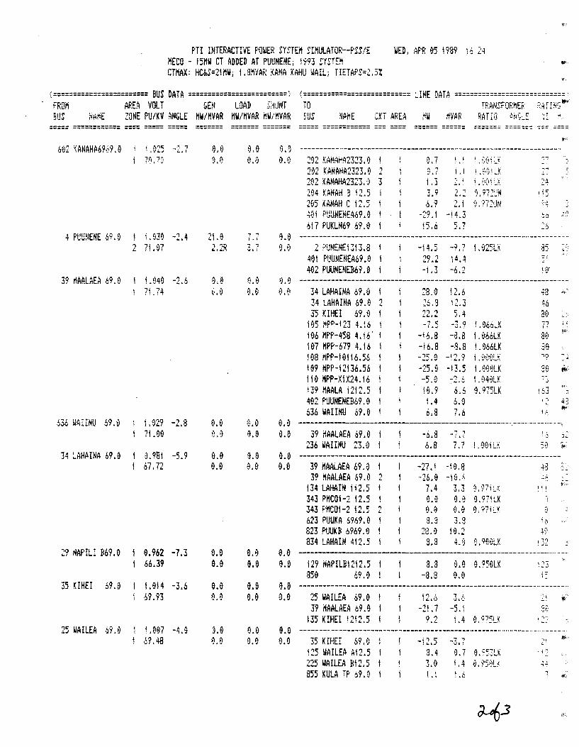
f'TI INTERACTIVE POWER SYSTEi'l S!MULATOR--PSS/E WED, APR 95 1989 i6 2q HECO - !5HW CT ADDED AT PUUNENE; 1993 ~YSTE~ CTI'IAX: HC~S=21MW; 1.3MVAR KANA KAH!J \JAIL; TIETAF'S=2.5%
(========================BUS DATA=========================;· <===========================LINE DATA============================· FF:OI'i AREA VOLT GE:N LOAD SHJtH TO r~:AilSFOF:ilEF: ·;:~ frf.IG • BUS NAriE ZONE PU/KV ANGLE MW/HVAR HW/HVAR HW/HVAR SUS !lAnE CKT AREA MW i!VAR ~AT IQ M;G~E ~I .d
===== ============ ==== ===== =====
602 KANAH~6969.9
4 PIJU:lENE 69.0
39 riAALAEA 69.0
.536 WAIINU 69.9
34 LAHAINA 69.9
29 NAPILI If69. 9
35 KIHEI 69.0
i .0i5 ··2.?
j .039 -2.4 2 7!.97
j .049 -2.6 1 71.74
i.929 -2.8 71.96
1.9B! -5.9 ,, ,.., 01. f.:.
9.962 -7.3 66.39
1.914 -3.6 ~'1. 93
25 WAILEA 69.9 I .087 -4.9 j /;'1.48
21.9 2.2R
e.a 9.9
9.9 e.a
e.e 9.~
======= ======= ===== ============ === ==== ====== ====== ======= ======= === ====
, ., \.\
'7 ! -..1& i
0.0 a.a
9.9 0.9
9.9 e.e
e.e e.o
B.B ------------------------------------------------------------------202 KANAHA2323.9 l 292 KANAHA2323.9 2 292 KANAHA2323.~ 3 294 XANAH B !2.5 l 2~5 KANAH C 12.5 1 ~al PUUNENEA69.8 I
6i7 F'UKUI69 69.8
1.3 3.9 2.2 9.~72~N
6,9 2,1 9.972UN -29.1 -14.3 15.6 5. 7
.-,""i
, iC: . ~ ..:
~~9 -------------------------------------------------------------------·· 2 <=·UNENE!3l3.8 1
4~1 PIJUNENEA69.D I 402 F'UUNENEI!b9. ~ I
-14.5
-1.3
-1.? l.e25LK 14.4 -6.2
as ···:-, .,;..·
e,9 ---------------------------------------------------------------------34 LAHAINA 69.9 34 LAHAINA 69.9 2 35 KIHEI 69.0 1
195 "PP-123 4.16 I 196 Mf'P-458 4. i6. l
!97 HPP-679 4.16 I 188 MPF'-19!16.56 199 HPP-12!36.56 110 MF'P-XfX24.16 i39 HAALA 12!2.5 482 PUUNENEB69.0 636 WAIINU 69.0 I
28.0' 12.6 26.8 12.3 22.2 5.4 -7.5 -3.0 ~.866LK
-16.8 -8.8 1.866LK -i6.8 -3.8 i.D66LK
-25.a -13.5 I .999LK -5.8 -2.6 I .949LY 19.9 6.6 9.975LK 1.4 6.8 6.8 7.6
48
~.,
i j
·,;
.-:. '~
a. o --------------------------------------------·----·-·-·- ·· -·-·-------··-··-· 9.8 39MAALAEA69.9 I -6.8 -t.<' ,'J J~
236WAIINU 23,0 i b.8 7.7 ~.E)EJiL~: Jtl ~;
8.0 ------------------------------------------------------------------8.9 39 MAALAEA 69.8 -27.1 -H"l.8 -\:3 .~,~
39 MAALAEA 69.0 2 -26.9 134 LAHAIN ii2.5 7.4 343 PHCOI-2 12.5 343 F'I'IC01-2 12.5 2 623 PUUKA 6%9.0 l 823 F~UKB 6969.9 834 LAHAIN 412.5
8.3 28.0 8.3
3.3 ~. 97i:J. 9.9 0.9"1LK 9.e 9, nu 3.8
HL2
:...~
a. e ----------------------------------------------------·--·-·-------·--·- .. --9.9 !29 NAPILBI212.5 I
a5e 69 .a 1 3.3 0.9 0.959LK
-8.8 9.0 • = I
e.e ------------------------------------------------------------·-·--------e.e 25 WAILEA 69.9 I
39 MAALAEA 69.9 I 135 KIHEI 1212.5 I
t2.6 '! I. ·.J & ,_,
-21.7 -5.\ 9.2 i .4
&.a ---------------------------------------------------·------------·-----·· e.e 35 KIHEI 69.0
125 ~AILEA Al2.5 225 WAILEA Bi2.5 855 KULA TP o9.9 i
3.4 3.El Li
-· .· . .;,;
9.7 9.95:LK f .4 L6
-.. ~'
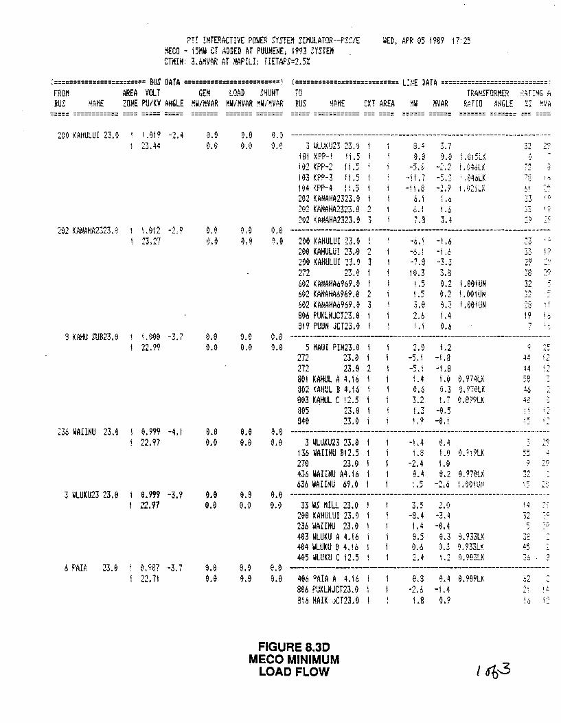
?TI INTERACTIVE POWER SYSTEM Sil'iULF!TOR--F'SS/E MECO - t5HW CT ADDED AT PUUNfNE; 1993 SYSTEH
WED, APR 05 1989 17:25
CTIUN: 3.6MVAR AT NAPILI; TIETAF'S=2.5%
\======================== BUS DATA =========================> <=========================== L:~E DATA ============================ FROM AREA VOLT GEN LOAD SHUNT 7J TRANSFORMEF: ,;:ATING A BUS NAME ZONE PU/KV ANGLE MW/MVAR MW/I'IVAR iiW/~VAR BUS ~lAME CKT AREA ~W MVAR RETIO ANGLE %I fWA
----- ============ ---- ----- -----
209 KAHULUI 23.0 ' l. e1 9 -2.4 23.44
202 KANAHA2323.0 i l .012 -2.9 23.27
9 KAHU SUB23. 0
236 WAIINU 23.9
3 WLUKU23 23.0
.s F'AIA 23. a
i. 000 -3.7 22.99
0. 999 -4.1 22.97
&.999 -3.9 22.97
~498? -3.7 22.71
0.9 0.0
a.e e.e
e.e e.e
e.e 0.0
0.0 1}.9
9.9 0.9
0.0 0.9
&.9 0.0
----- ============ --- ----
8.9 --------------------------------------------------------------------0.0 3 ~LlJKU23 23.')
191 KPP-1 II .5 I
102KF'P-2 !!.5 ! 93 ~F'P-3 t 1.5 ! 84 ~PP-4 1 t • 5 202 KANAHA2323.9 202 KANAHA2323.9 2 262 ~AMAHA2323.9 3
8.4 3.7 9.9 0.9 \.0\5~X
-5. ~- -... 2 ! . 046LK -\L"l -5.2 •,94oLK -11,8 -2,9 1 .02tLX
s. t \.6 b, i t ,6 7.:3 3.4
?2 a
11 i (I __ _,
0.0 --------------·------------------------------------------------------~.9 290 KAHULUI 23.0
200 KAHULUI 23.-9 2 290 KAHULUI 23.0 3 2?2 23.0 602 KANAHA6969.0 I 602 KANAHA6969.0 2 602 KANAHA6969.0 3 806 F'UKLNJCT23.9 819 PUUN JCT23.9
-6.! -1.6 -6£1 -1 ;6 -7.8 -3.2 10.3 3.8 ! .5 0.2 t.OOIUN t .5 9.2 1.901UN 3.9 9.2 I.OOIUN 2.6 1.4 l.! 0.6
38 ~~' 1·1 = ·J<.
!9 ., 0.0 --------------------------------------------------------------------U) 5 MAIJI PIN23.0
272 23.9 272 23.9 2 a01 KAHUL A 4.16 :302 KAHUL B 4.16 803 KAHUL C tZ.5 :305 23.9 840 23.9
2.9
-5. t 1.4 9.6
L2 -1.3 -La La 9.974LK 9.3 e.970LK 1. 7 9. 8·?9LK
t. 9 -9. i
44 H 58 46 h.~,
'1(:
; I
'"" ! _,
. ;
9~0 --------------------------------------------·----------------·----··-··-8.9 3 WLUKU23 23.0
136 WAIINU Bl2.5 279 23.9 436 WAIINU A4.t6 636 WAIINU 69.0
-j .4 9.4 i.8 1.0 0. :;PLK
-2.4 1.9 0.4 9.2 9.979LK
l;;:: -·.:·. ; -' ..;_ ~:
e~e ---------------------------------------------------------------------9.0 33 WS MILL 23.0
206 KAHULUI 23.0 236 WAIIHU 23.0 403 WLUKU A 4.16 404 WLUKU B 4.!6 405 wLUKU C 12.5
2.~ 3.5 -8.4 -3.4 1.4 -{).4 9.5 9.3 9.933LK
~.3 9.?33LK 1.2 0. 903LK
0.6
1'1 J.;.
Jt ,,_,
e,a --------------------------------------------------------------------0.0 406 PAIA A 4.16
8&6 PUKLNJCT23.9 816 HAIK JCT23.0
e.a -2.6
L8
~.4 0.909LK -1.4
0.9
.-, ~
..;..:
'" ,_
FIGURE 8.30 MECO MINIMUM
LOAD FLOW t!b-3
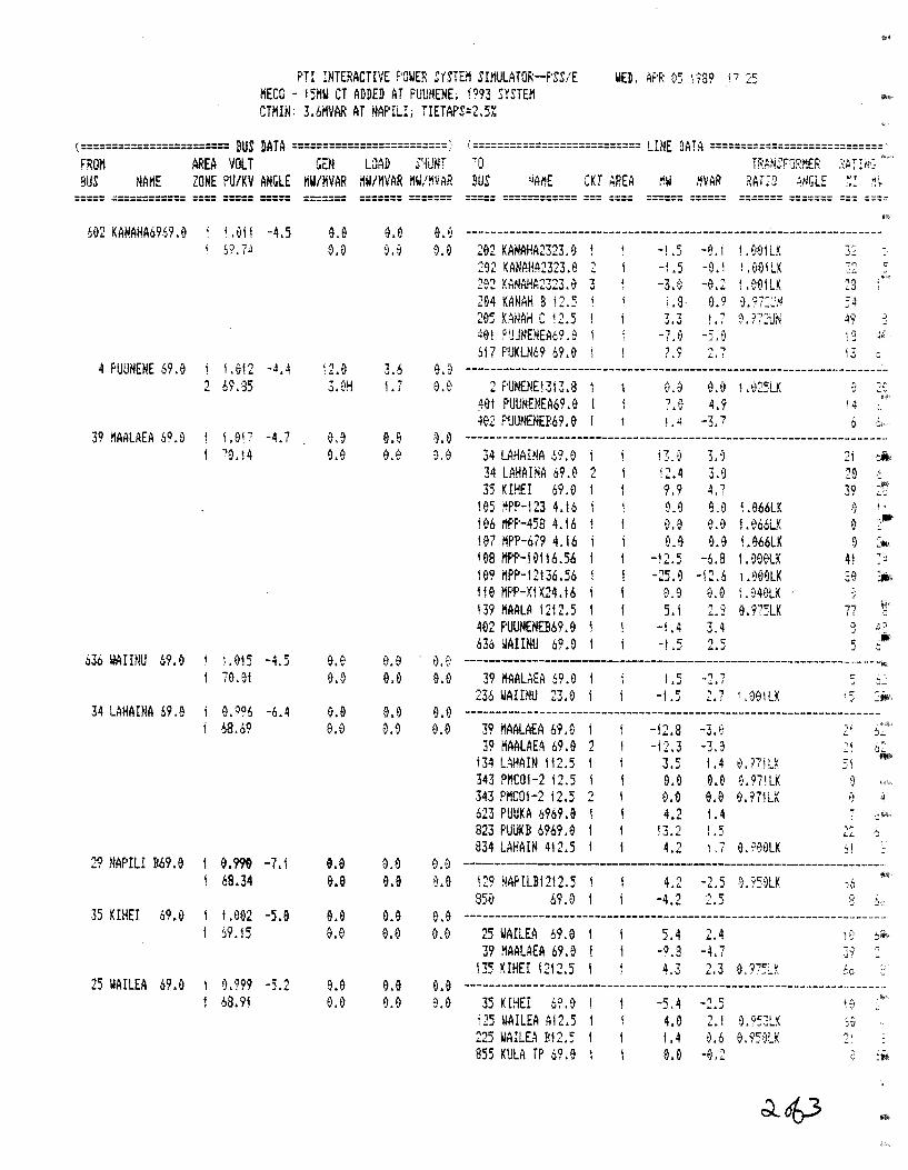
PTI INTEF:ACTIVE F'OWER SYSTEM SIMULATOR--f'SS/E MECG - 15MW CT ADDED AT PUUNENE; ! 093 SYSTEM CTI1IN: 3.611VAR AT NAPILI; TIETAPS=2.5%
...
WED' AF'R tl5 i "?89 I 7 25
( ======================== BUS DATA ========================= ;: ( =========================== LHlE DATA ============================' FROi'l AREA VOLT GEM LJAD S~1iJNT .,.0 TFAt!EFOF:MEF: ;;:AT:!1·~" 9US NAtiE ZONE PU/KV AMGLE MW/MVAR liiri/HVAR i'IW/HVAR BUS 'iAi'!E CKT AREA ,~W HVAR RAii9 .~!JGLE :: -~~
===== ============ ==== ===== ===== ======= ======= ===== ============ === ==== ------ ------------ ------ ======= ======= === ====
602 KANAHA6969.0 i.Ol I -4.5 e.o e.e 9.0 -------------------------------------------------------------------i b'?. ?il 0.0 0.0 0.0 202 KANAHA2323.0 -!.5 -~. i 1 .t1EliLK ~~.::..
292 ~ANAHA2323.0 2 -L5 -9. I 1.001 LK !-'1 <; ...... 202 KANAHA2323.0 "l -3.0 -0.2 1.001LK 23
\tA' .., 204 KANAH B i2.5 i .8 0.9 9:~?:~.-J 5j 205 KANA~ c 12 .. 5 7 7 ' ., 0.?72UN 49 :·
·.J ~ oJ I ~ i ·~
4et P'JUNENEA69. 9 -?.0 -5.9 ~ .-:: ,. S17 F'UKU!69 ~9.9 7.9 '
., '7 ,a;.,! ,..,
4 PUUNENE 69.e 1.012 -4.4 \2.0 3.6 ~~0 --------------------------------------------------------------------') 69 ,!35 3.~H L7 ~.0
., f'IJN£NEt3i3.8 i 0.0 0.9 t .~25LK 0 .. ;;
~01 PUUNENEA69.0 I 7~6 4.9 I 4 h'
402 F'UUNEN£!!69.0 f j ;l -3.7 6 -~· 39 MAALAEA 6Q,Q l,Oi 7 -4.7 0.9 ~.Q e.a -------------------------------------------------------------------··
"'0. 14 9.~ ~.tl ~.e 34 LAHAINA 69.0 i3.0 3.1 2i .).' 34 LAHAINA 69.0 'i i2~4 3.9 29 .. 35 KIHEI 69.0 9.9 4 ., ,, 39
105 ~PP-123 4.16 9.9 9.9 L066LK "' ,,
·.;
:,1111 196 i!PP-458 4.16 i 9.9 0.0 1. ti66LK 9 107 iiPP-679 4.16 i 9.9 9.0 l .~66LK 9 :~ !08 I'!Pf'-19116.56 1 -12.5 -6.8 1.900LK 4f "';,;, -· te9 HPP-12136.56 I -25.9 -12.6 L999LK 20 • 119 I'!PP-X1X24.16 1 0.9 0.0 i. 04(lLK ~-'
139 HAALA 1212.5 I 5.1 2 .. 3 9.975LK .,.., i>\! II :--!
402 PUUNENEII69.0 -1.4 3.4 ·J ;<J .J .,
636 ~AIINU 1!9.9 -1.5 ') c: 5 &:.,~..; -~·
636 WAIIilU 69.0 i .915 -4.5 0.0 El.fl i). ~) -------------------------------------------------------------.. J!
70.01 e.e e.o 0.9 39 HAALAEA 69.0 t 1.5 _, 1 r: i.. ~ I --
236 WA!INU 23.0 j -1.5 ' , I .00\LK ,,. 2ill ..:.4! . _,
34 LAHAINA 69.e 0.096 -6.4 0.9 e.e e.e -------------------------------------------------------------------68.69 e.o 0.0 0.0 39 i\AALAEA 69.0 -i2.8 -3~€' 21 0..;.
~q HAALAEA 69.0 ') -i2.3 -3.3 'l •J.:.. j, 1.. -· i34 LAHAIN 112.5 3.5 1.4 ~.17iLX 51
m•
343 PMC01-2 12.5 0.0 e.e 0.97\LK 0 343 f'I'!C01-2 i2.5 2 ~.0 e.a ~.97\LK ~ 4
6.,., i..J PUUKA .s969 .e 4.2 1.4 ~ -,:!~i-·
a')~ F'UUKB 6969.0 13.2 1.5 -,--~ .. .:~
~"" 834 LAHAIN 412.5 4.2 1 ~ 7 G.9~0LK j!
29 NAPILI B69.9 e.m -7.1 e.e 0.0 0.'~ ---------------------------------------------------·-----------------68.34 e.e e.e ~.e pq ~APILB12t2.5 1 4.2 -2.5 9.'?59LK }6 ill'' -· 85El 69.0 1 -4.2 245 8 ·},,
35 KIHEI 69.f) !.9fl2 -5.0 e.e e.e 0.e --------------------------------------------------------------------59.15 e.e e.o ~.0 25 WAILEA 69.0 5.4 2.4 ~ .:) -~~-j· ••
"lQ
"' HAALAEA 69.0 l -9.3 -4.7 3? 135 KIHEI 1212.5 ! 4.3 2.3 0.97~L~ :~() -
25 WAILEA 69.0 &.'?99 -5.2 9.9 e.o 0.9 -------------------------------------------------------------··-----·· 68.91 0.0 0.0 0.0 35 KrHEI 6?.9 -5.4 •1 c: -.... .; iQ
i25 WAILEA Al2.5 4.0 2.1 0.953LX Jtj
225 WAILEA B12.5 1.4 0.6 0.950LK "" ~
ass KULA iP 69.9 0.0 -el2 ':_: :IJili
~o63 ••
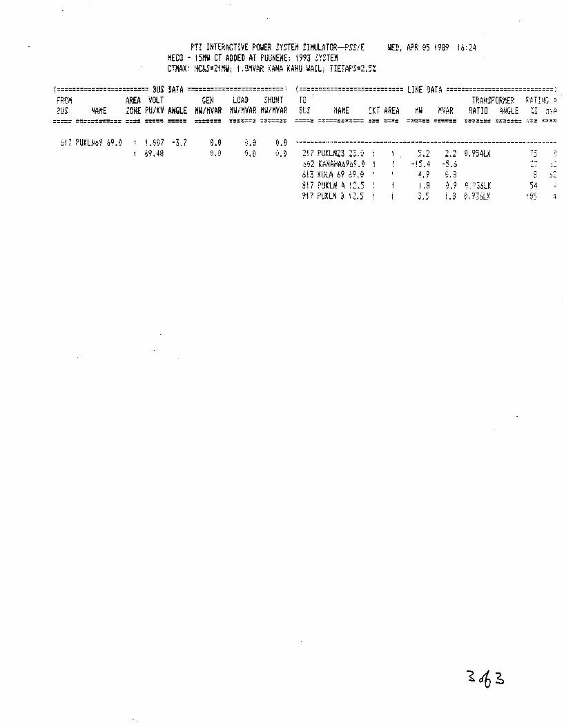
F'TI INTE:RACTIVE POWER SYSTEM SH!ULATOR--f'SS/E liED, APR ~5 1999 !6:24 MECO - 151'\W CT ADDED AT PUUNENEi 1993 SYSTEM CTMAX: Ho..S=2HIW; i .S!'!VAF: ~ANA KAHIJ IIAIL; TIETAF'S=2.5%
( ======================== BUS DATA ========================= ·,. ( =========================== LINE DATA ============================ > FROi'i AREA VOLT GEN LOAD SHUNT TO TF:AtiSFORhE~: ~·A TV!~ -~ E!US ~AilE ZONE PU/KV ANGLE MW/MVAR nW/MVAR iiW/HVAR BUS ilAHE CKT AREA nW ~VAR RATIO ~.~GLE ~I ~·,;.
===== ============ ==== ===== =====
bl? PUKLh69 69.9 i t .907 -3.7 6'?.48
o.e
======= ======= ===== ============ === ==== ====== ====== ======= ======= === ====
9~0 ------··------------------------------------------------------·----··-·· 217 F'UKLN23 23. ~j <: "· ·1 'l 9.954LK ij ..;,.;.... ..... ~fi2 Kt~NAHA6969.9 -l5. 4 -5.6 :.-i ...:.:...
bi3 KULA 69 69 .€1 • 4.9 2.3 :3 J2 817 f''JKLN A .. , '\
! ...... ,., 1.8 ~a·~ ~. ::36LK 54 ~
'?17 PUKL~ B L2.5 -, " .J.~· } .3 €1 ~ !?2bLX 1 El5
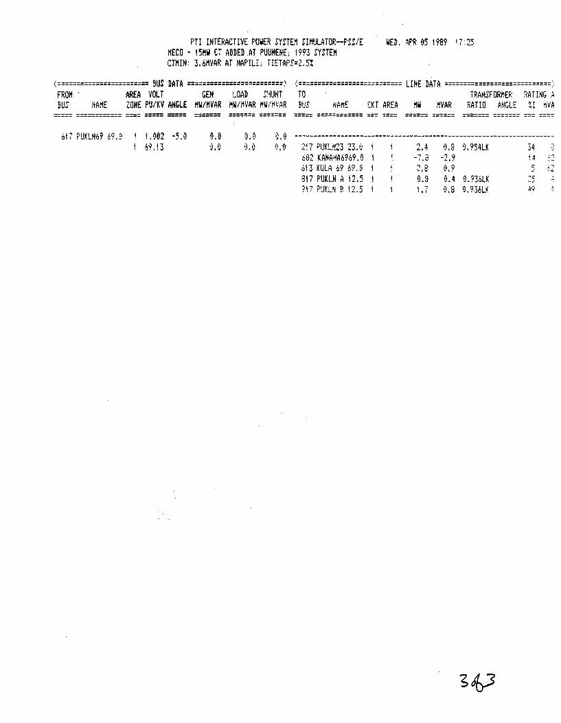
PTI INTEF:ACTIVE POWER SYSTE.i1 SIMUL4TOF:--F'SS/E MECO- !5HW CT ADDED.AT PUUNENE; 1993 SYSTEM CTIH~: 3.6MVAR AT NAPILI; TIETAf'S=2.5!
WED. APR &5 1989 17:25
<======================== BUS DATA =========================> <=========================== LINE DATA ============================> FROH · AREA VOLT GEN LOAD SLfUNT TO TRANSFORMEF: RATING ::. BUS NAME ZONE PU/KV ANGLE MW/11VAR 11W/11VAR 1111/~VAR BUS NF11E CKT AREA ~~~ ~VAR RATIO AiiGLE ZI i'IVA
===== ============ ==== ===== =====
617 PUKL.~69 69.9 1.002 -5.0 69.13 0.0
======= ======= ===== ============ === ~=== ====== ====== ======= ======= === ===~
--------------------------------------------------------------------2l7 F'UKL!-i23 23.~ ; 2.4 0.8 0.954LK 34 ;
J
602 KANAHA6969.9 -7.8 -2.9 j4 ~·.:..
bl3 KULA 69 o9.a 2.8 0.9 5 ·~·2
3!7 PUKLN A 12.5 0.3 0.4 0.'136LK ·':C' l ::...)
917 F'UX.LN B ; ') -.... ) ! 1.7 0.8 9. '?.36LK 4'?
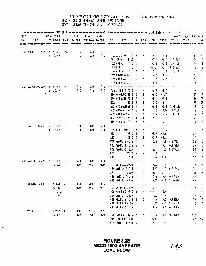
PTI INTERACTIVE POWER SYSTEM SHtULATOR--PSS/E MECO - !SHW CT ADDED AT PUUNENE; 1993 SYSTEM
WED I Af'~: 95 t 999 i 7: 25
CTDAY: l.SMVAR KANA KAHU WAIL; TIETAPS=2.5:t
C ======================= BUS DATA ========================= > ', =========================== LINE DATA ============================ '-FROM AREA VOLT GEM LOAD SHUNT TO TF:ANSFOF:ns~: FNI~'~ ~ BUS NAME ZONE PU/KV AHt;LE MW/HVAR MW/MVAR liW/MVAR BUS NAME CKT AREA liW MVAR RATIO ANGLE ::I MVA
----- ============ ---- ----- -----
20t) KAHULUI 23.0
292 KANAHA2323.9
8 KAHU SUB23.0
236 WAI!NU 23.0
3 WLUKU23 23.9
L020 -2.3 23.45
LOll -2.8 23.26
22.34
9.997 -4.2 22.93
6.994' -4.3 22.u·
6 PAIA 23.0 1 0.962 -4.2 22. !2
o.9 t>.O
a.o o.o
e.e a.o
e.e o.e
o.o 9.9
a.a 0.9
a.o o.e
e.e o.e
9.0 ~.0
----------------- ------------ --- ----
~.0 --~--------------------------------------------------------·~--------3 WLUKU23 23.0 1
101 KPP-\ 11.5 1L5
i03 KPP-3 il.5 !tl4 (Pf'-4 I; .5 202 KANAHA2323.0 292 KANAHA2323.e 2 292 KANAHA2323.9 3
-5.9 -5.0
-t\.7 -i i.O
.~.6
6.6 3.4
4.4 42 "'=i
-1.5 UI~LK 7j
- '! '~ i . 04.SLX -5 ~ ~ 1 • 046LX -2,8 1,~21LK
l q . ,.., I. p ....
3t a.a --------------------------------------------------------------------0.9 290 KAHULU! 23.9
209 KAHULUI 23.& 2 299 KAHULUI 23.9 3 272 23.0 602 KMIAHA6969 .& 692 KANAHA696'1. 9 2 602 KANAHA6969.& 3 806 f'UKLNJCT23.9 819 PUUN JCT23.9
-6.5 -1.7 -6£5 -; ,7 -8.4 -3.5 i5.5 6. j -fl.3 -9.8 l.901 UN -0.3 -9.8 I .091UN -9.7 -1.6 i.B9!UN 5.2 3.~ 2.0 I .I
3! 58 :·? j 9 19 !7 i;
38 14
!•
"'· ·.;
o.a ---------------------------------------------------------------------0.& 5 HAUI P!N23.0
272 23.0 272 23.9 2 80! KAHUL A 4.16 902 KAHUL B U 6 803 KAHUL C i2.5 895 23.0 840 23.&
3.8 2.3 -7~ 7 -2.8 -7.7 -2.8 2.6 3,& ~,974LK
• 1.1 9. 7 0. 9 79LK 6.1 1.2 0.899LK &.3 -1.1 !. 4 -0.4
67 67
i34
83
'-, .. ..;..
' 1 . -, a.e -----------------------------------------------··--------------------0.& 3 WLUKU23 23.0
136 WAIINU Bl2.5 279 23.0 436 WAIIMU A4.16 636 WAIINU 69.0
3.5 -0.4 9.3
-6.2
i .4 2.9 e.?I9LK
0.4 0.97uLK 1.001UN
,-, 0
S2 44
4 -, =-·
0~0 --------------------------------------------------------------------&.9 33 iiS MILL 23.9
290 KAHULUI 23.& 236 WAI!NU 2~.9 403 WLUKU A 4.16 494 ~LUKU B 4.16 405 WLUKU C 12.5
' , ll. f
-i 1.1 -2.3
l .9 1.2 4.6
3.9 -3.9 -u
9.933LK 0.5 9.6 ti.933LK Q.2 9.9~3LK
2? 42
88 j
a. a ----------------------------------------------------------------·· 9.& 4~6 PAIA A 4.!6
806 F'UKLNJCT23.0 816 HA!K JCT23.0
' r: 1 ,J
-5.9 9. 9 0. '?•)9LK
-2.3 42 ;j
FIGURE 8.3E MECO 1993 AVERAGE
LOAD FLOW
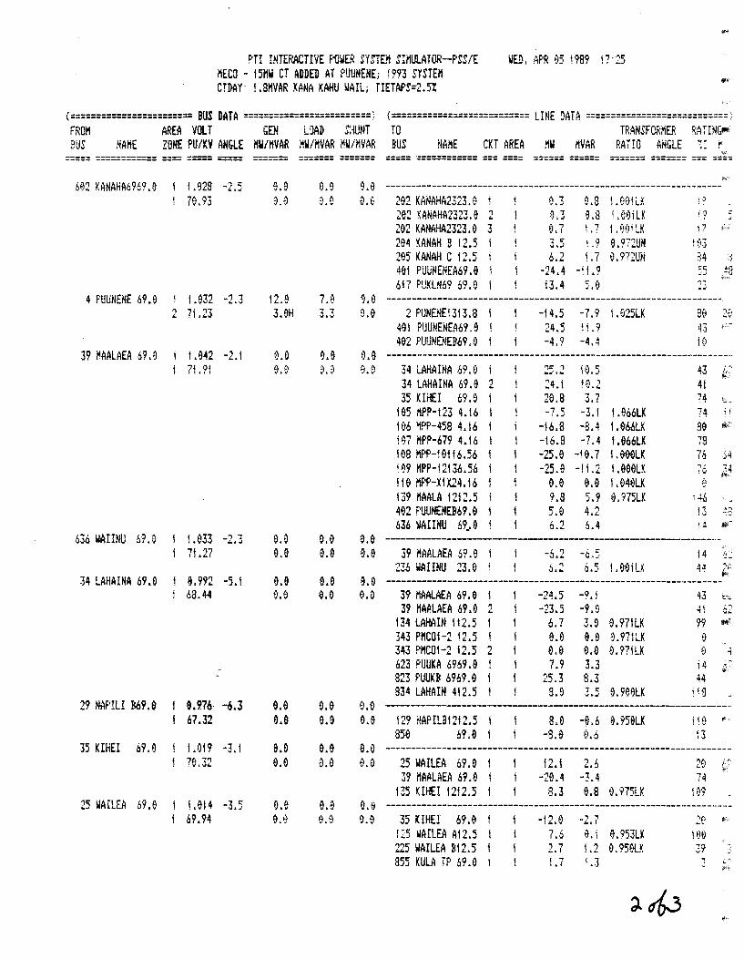
PTI INTERACTIVE POWER SYSTEM SIMULATOR--PSS/E MECO - 15HW CT ADDED AT PUUNENE; f993 SYSTEM
WED, APR 05 1989 1?·25
CTDAY: l.BMVAR KANA KAHU WAIL; TIETAPS=2.5%
<======================== BUS DATA =========================> <=========================== LINE DATA ============================> FROM AREA VOLT GEN dAD =:-!UNT TO TRANSFORMER ;:ATIN{;I!II; BUS .~AME ZONE PU/KV AH&LE HW/MVAR i!W/MVAR i!W/HVAR BUS HAHE CKT AREA i'!W I'IVAR RAi!O ANGLE ~I ~
===== ============ ==== ===== =====
6~2 KANAHA6969.0 j .928 -2.5 79.93
4 PUUNENE 69.9 t 1.932 -2.3 2 71 .23
39 ~AALAEA 69.0
636 WAIINU 61.0
34 LAHAINA 69.0
29 NAPILI !169.&
35 KIHEI 69.9
25 WAILEA 69.9
1.942 -2.1 71.91
1.933 71.27
e. 992 -5.1 68.44
e.976· -6.3 67.32
1.019 -3.1 79.32
! .014 -3.5 69.94
9.0 ~.0
12.0 3.9H
0.0 0.~
0.9 e.o
0.0 O.fJ
e.e o.e
e.e 0.0
------- ------- ===== ============ === ==== ====== ====== "" ======= ======= === ==== ------- -------
0.9
e.e
0.0 e.e
o.e e.a
e.e 0.0
e.e 0.0
o.a 8.8
94a ------------------------------------------------------------------9.~ 292 KANAHA2323.0
202 KANAHA2323.9 2 292 KANAHA2323.a 3 294 KAHAH 9 12.5 295 KANAH C 12.5 491 PUUNENEA69.9 617 PUKLN69 69.0
0.3
e,7 3,.5 6.2
-24.4 i3.4
0.3 1.00lLK 9.8 '.091LK L 7 1.NJiLK !.9 9.972UH L 7 0. ?72UN
-l L9 5.0
34 :<;
9.9 ------------------------------------------------------------------~.9 2 PUNENEl3!3.8 I
491 PUUNENEA69.0 i 492 PUUNENEI!69.0 1
-!4.5 -7.9 1 .025LK 24.5 1i.9 -4.9 -4.4
a.e -------------------------------------------------------------------·-34 LAHAINA 69.0 34 LAHAINA 69.0 2 35 KIHEI 69.9
105 MPP-123 4.16 106 ~PP-458 4.16 !~7 MPP-679 4.16 198 MPP-!0116.56 !~9 MPP-!2136.56 110 Mf'P-XIX24.16 139 HAALA 1212.5 492 PUUNENEB69.0 636 IIAIIHU 69_. 9
24. i 20.8
-16.8 -16.8 -25.0 -25.9
e.o 9.8 5.9 6.2
!0.5 10.2 ~ ., j, I
-3.! -8.4 -?.4
-!0.7 -!1.2
9.0 5.9 4.2 6.4
!.966LK 1.066LK 1.966LK ! .OOOLK I.GG9LK l .040LK G.975LK
43 41 74 ' 74 \ i ao ""'-78 76 .l4
?6 ~,4
e.e ----------------------------------------------------------------~-0.9 39 MAALAEA 69.9 !
236 WAIIHU 23.0 i -6.2 -6.5 6.2 6.5 1 .99iLK
14 44 ;,:,
~
9.0 ------------------------------------------------------------------0.0 39 MAALAEA 69. e
39 MAALAEA 69~6 2 134 LAHAIN 112.5 343 PHCOI-2 12.5 ! 343 F'HCOI-2 12.5 2 623 PUUKA 6969.0 923 PUUKB 6969.0 834 LAHAIH 412.5
-24.5 -9.1 -23.5 -9.0
6.7 3.fJ 0.971LK a.e e.o e.97lLK e.e o.e 0.971LK 7.9 3.3
25~3 8.3 8.9 3.5 8.988LK
43 t_
4i 99 .,.,
{i .;
14 ;: 44
a.e -------------------------------------------------------------------·· O.e 129 I!APILBI212.5 1 8.0 -8.6 8.959LK 1 ;e "
sse 6?.o 1 -s.e o.o l3 e&a --------------------------------------------------------------------8.& 25 WAILEA 69.0
39 MAALAEA 69.8 ! 135 KIHEI 12!2.5 l
12.1 2.6 -28.4 -3.4 74
8.3 0.8 0.975LK 9.~ --------------------------------------------------------------------9.0 35 KIHEI 69.8
125 WAILEA Al2.5 225 WAILEA BI2.S 955 KULA fP 69.8 1
-12.0 7.6 2.7 1.7
U 8. 953LK ! .2 e. 959LK i .3
39
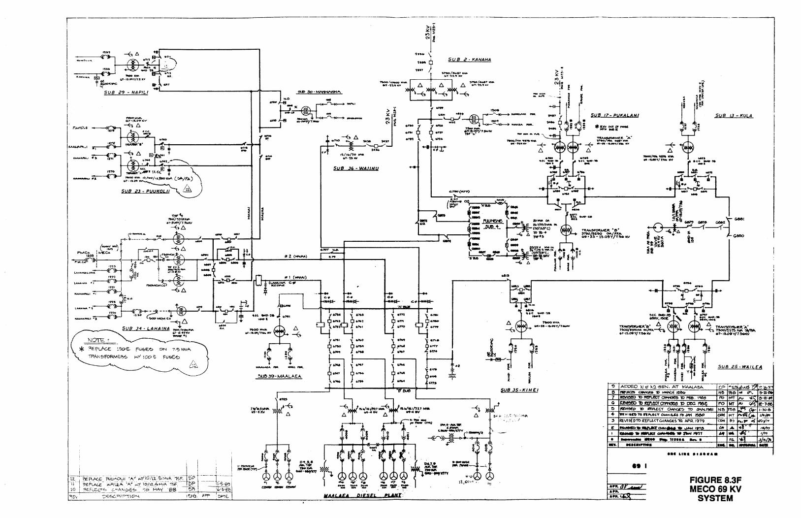
,-:j :®.7"£{)
---~.-4(~ -- i "::!. ~e.-.. ..... " Gf (,'T·IJ.O'IIIT/1.'1 I(Y
T ~"-""' &- ..,,
MoNCL."'"'
SUB 29 - NAPIL/ ~--------------....Jt----,
T~f.t 19o0/~)15-
·7·1t~/7.!k.I<V
~.6.
..... .I.
-II! .... -
+ ... ' . .::~·'· J ..... ~00 ....... !::>.
-'•I •. CJIIt/T.._ KV ~
a : ~t ~t
5Ur> 39- MAALAEA
SUB .36 - WAIINU
~·"'' ~·- ~·-.. ~ ·- ..... ·- .... ~.,
f·- T ·~· T= .... .. ,.... ,··- ·, ·- ·, .....
·rr eue L-- -
MAALA£4 Dt£5£4 eUHl:
SU 8 2 • KANAHA
~~/.-c.&? a-. C.'7•"1'2 .......
ii :
i i
--........ --...
SUB 35-KIHE:I
SUS 11'- PUKALANI
*ltrN OUT or,_ NTN ll.el£
. ..
~ ACOEO >.t e ~'J. sEN, AT h1AALA~ 6 IWl.fG1!> CIWtl4l!a 'I) ..w.cll l!leGo 7 ~ 10 l'!l:I'U!CT ~ 10 PUI. I~ y ~ 1> mtear~ .., ceo. ~e !) IQM~ 'I) ll!fU:CT OWKof~ 11:> ~1'381
+ [IN Yl U'O 1'6 ft .... llCT OW. U$ 7lJ Ji'tt ~
~ REVIS[I)'Ttl REfLLCTQ.IANc.t~ 1Q APR. 1979 - c ---....Mr~-.......,.97&
I ~-~~-~,.,T
• ............. ._. 1 ..... -· en. MltltPYtea
••• ua• •••••••
•• I
SUB i!S -WAlLE" A
DP Ne 1'0
ro N~
~
CDH
LA
~ ... MT ~~( .. 114/'!!_ ~) r.,. .. ~ lv;y>.
•· I~. '/" F.ca. I ~ .J/,./16 ... _ .....
Af'II.OT ....._j ..... FIGURE 8.3F MEC069KV
SYSTEM
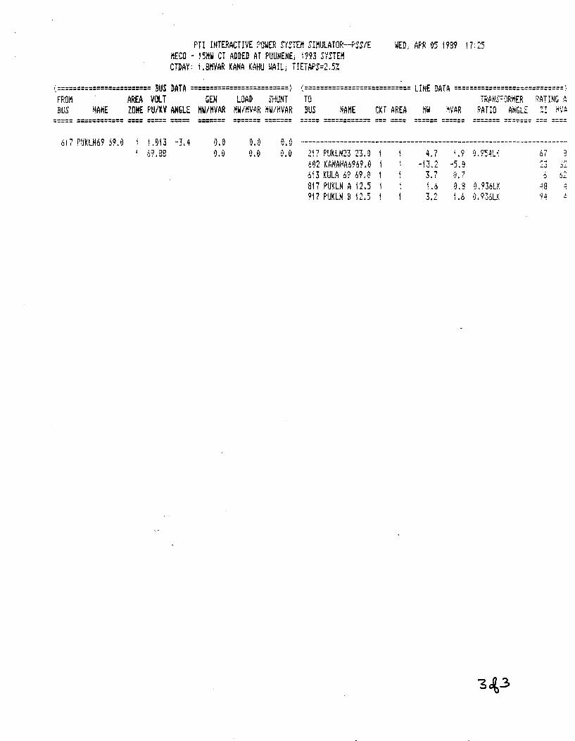
PTI INTERACTIVE f'OWEF; SYETEM SIMULATOR-PSS/E HECO - !5MW CT ADDED AT PUUNENE; 1993 SYSTEM CTDAY: LSMVAR KANA KAHU WAIL; HETAf'S=2.5Z
WED, APR 95 i 989 17 : 25
(======================== BUS DATA =========================> (=========================== LINE DATA ============================~ H;OI'I AREA VOLT GEN LOAD SHUNT TO TRANS!="ORMEF; \ATING A BUS ~AHE ZONE PU/KV ANGLE HW/HVAR HW/HVAR HW/MVAR SUS NAME CKT AREA MW MVAR RATIO ANGLE ~I ~VA
===== ============ ==== ===== =====
617 PUKLN69 59.0 j .913 -3.4 • 6'? .88
f).O
0.0
====== =======
0.0 0.0
===== ============ === ==== ====== ====== ======= ==~==== === ====
--------------------------------------------------------------------217 F'!JKLN23 23.~ 4.7 i .9 9. 954L~: L~
lJf
Ml2 KANAHA6969 .e -13.2 - .9 :3 . '" ·J..:.
6~3 KULA 6'? 69.0 ~ ., .., 6 62 .. LI . '
317 PIJKLN A 12.5 1.6 .s f). 936LK .:iS ..
917 f·!JKLN B 1'1"" .:..~.) 3.2 .6 ~l93:5LK 94 4
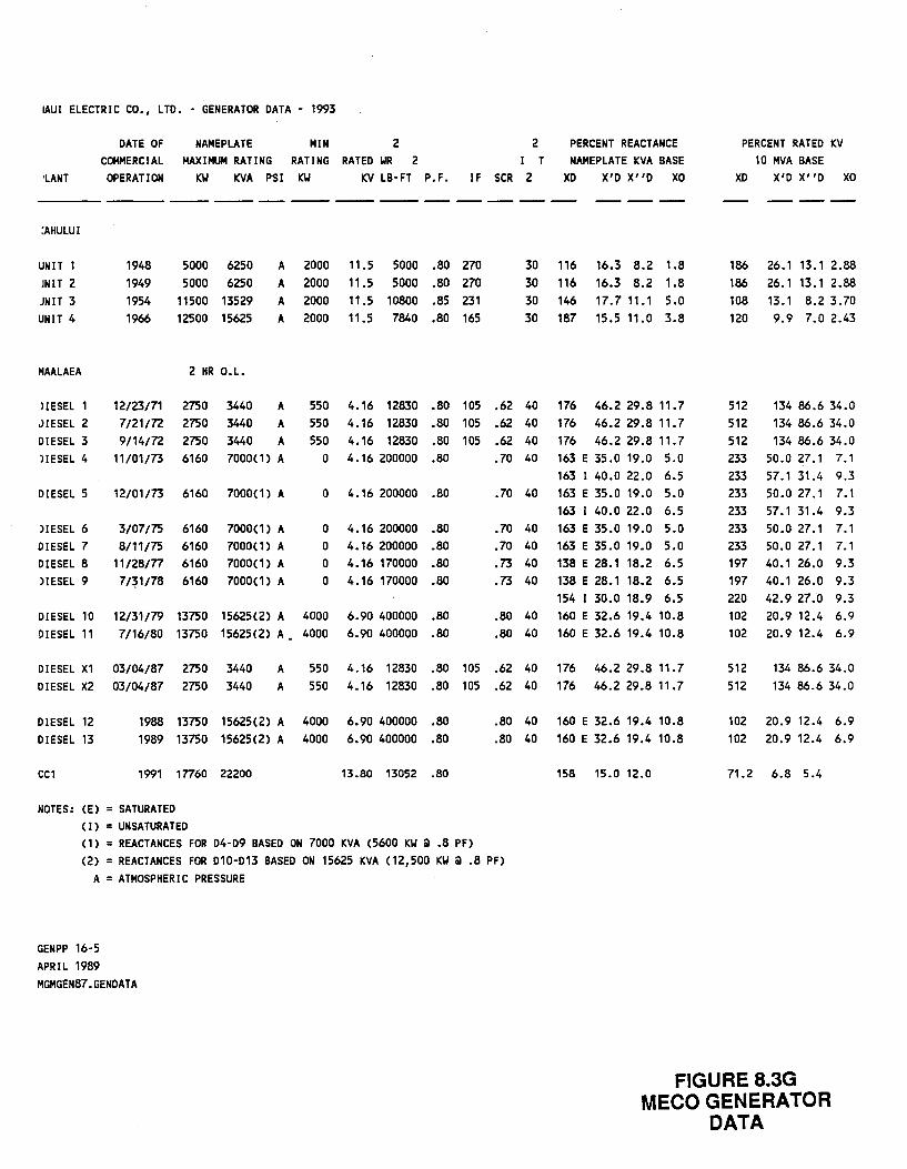
IAUI ELECTRIC CO., LTD. - GENERATOR DATA - 1993
1LANT
DATE OF COMMERCIAL
OPERATION
NAMEPLATE MIN 2 MAXIMUM RATING RATING RATED WR 2
KW KVA PSI KW KV LB·FT P.F.
2 I T
IF SCR 2
PERCENT REACTANCE NAMEPLATE KVA BASE
XD X'D X''D XO
---- ---- --- --- -- ------ -- -- -- -- -- -- -- --:AHULUI
UNIT 1 JNIT 2 JNIT 3 UNIT 4
MAALAEA
1948 1949 1954 1966
5000 6250 5000 6250
11500 13529 12500 15625
2 HR O.L.
A 2000 A 2000
11.5 5000 .80 270 11.5 5000 .80 270
A 2000 11.5 10800 .85 231 A 2000 11.5 7840 .80 165
30 30
116 16.3 8.2 1.8 116 16.3 8.2 1.8
30 146 17.7 11.1 5.0 30 187 15.5 11.0 3.8
liESEL 1 JIESEL 2 DIESEL 3 HESEL 4
12/23/71 2750 3440 7/21/72 2750 3440 9/14/72 2750 3440
A
A
A
550 4.16 12830 .80 105 .62 40 550 4.16 12830 .80 105 .62 40 550 4.16 12830 .80 105 .62 40
176 46.2 29.8 11.7 176 46.2 29.8 11.7 176 46.2 29.8 11.7 163 E 35.0 19.0 5.0
DIESEL 5
)IESEL 6 DIESEL 7 DIESEL 8 )IESEL 9
11/01/73 6160 7000(1) A
12/01/73 6160 7000(1) A
3/07/75 6160 7000(1) A 8/11/75 6160 7000(1) A
11/28/77 6160 7000(1) A 7/~1/78 6160 7000(1) A
0 4.16 200000 .80
0 4.16 200000 .80
0 4.16 200000 .80 0 4.16 200000 .80 0 4.16 170000 .80 0 4.16 170000 .80
DIESEL 10 12/31/79 13750 15625(2) A 4000 6.90 400000 .80 DIESEL 11 7/16/80 13750 15625(2) A. 4000 6.90 400000 .80
.70 40
.70 40
.70 40
.70 40
.73 40
.73 40
163 I 40.0 22.0 6.5 163 E 35.0 19.0 5.0 163 I 40.0 22.0 6.5 163 E 35.0 19.0 5.0 163 E 35.0 19.0 5.0 138 E 28.1 18.2 6.5 138 E 28.1 18.2 6.5 154 I 30.0 18.9 6.5
.80 40 160 E 32.6 19.4 10.8
.80 40 160 E 32.6 19.4 10.8
DIESEL X1 03/04/87 2750 3440 DIESEL X2 03/04/87 2750 3440
A
A
550 4.16 12830 .80 105 .62 40 176 46.2 29.8 11.7 550 4.16 12830 .80 105 .62 40 176 46.2 29.8 11.7
DIESEL 12 DIESEL 13
1988 13750 15625(2) A 4000 6.90 400000 .80 1989 13750 15625(2) A 4000 6.90 400000 .80
CC1 1991 17760 22200
NOTES: (E) = SATURATED (I) =UNSATURATED
13.80 13052 .80
(1) =REACTANCES FOR D4-D9 BASED ON 7000 KVA (5600 KW Q .8 PF)
.80 40 160 E 32.6 19.4 10.8
.80 40 160 E 32.6 19.4 10.8
158 15.0 12.0
(2) = REACTANCES FOR D10-D13 BASED ON 15625 KVA (12,500 KW Q .8 PF) A = ATMOSPHERIC PRESSURE
GENPP 16-5 APRIL 1989 MGMGEN87.GENDATA
PERCENT RATED KV 10 MVA BASE
XD X'D X' 'D xo
186 26.1 13.1 2.88 186 26.1 13.1 2.88 108 13.1 8.2 3.70 120 9.9 7.0 2.43
512 512 512
134 86.6 34.0 134 86.6 34.0 134 86.6 34.0
233 50.0 27.1 7.1 233 57.1 31.4 9.3 233 50.0 27.1 7.1 233 57.1 31.4 9.3 233 50.0 27.1 7.1 233 50.0 27.1 7.1 197 40.1 26.0 9.3 197 40.1 26.0 9.3 220 42.9 27.0 9.3 102 20.9 12.4 6.9 102 20.9 12.4 6.9
512 512
134 86.6 34.0 134 86.6 34.0
102 20.9 12.4 6.9 102 20.9 12.4 6.9
71.2 6.8 5.4
FIGURE 8.3G MECO GENERATOR
DATA
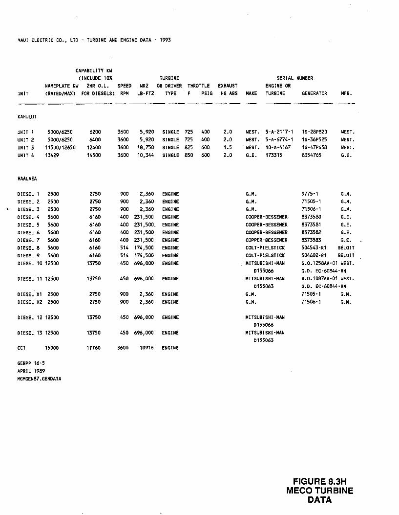
"lAUI ELECTRIC CO., LTD - TURBINE AND ENGINE DATA - 1993
CAPABILITY KIJ
(INCLUDE 1DX TURBINE NAMEPLATE KW 2HR O.L. SPEED WR2 OR DRIVER THROTTLE EXHAUST
'JNIT CRATED/MAX) FOR DIESELS) RPM LB-FT2 TYPE F PSIG HG ABS
------ --- --- --- -- -- -- --KAHULUI
UNIT 1 5DD0/6250 6200 3600 5,920 SINGLE n5 400 2.0 UNIT 2 5000/6250 6400 3600 5,920 SINGLE n5 400 2.0 UNIT 3 11500/12650 12400 3600 18,750 SINGLE 825 600 1.5 UNIT 4 13429 14500 3600 10,344 SINGLE 850 600 2.0
MAALAEA
DIESEL 1 2500 2750 900 2,360 ENGINE DIESEL 2 2500 2750 900 2,360 ENGINE DIESEL 3 2500 2750 900 2,360 ENGINE DIESEL 4 5600 6160 400 231,500 ENGINE DIESEL 5 5600 6160 400 231,500. ENGINE DIESEL 6 5600 6160 400 231,500 ENGINE DIESEL 7 5600 6160 400 231,500 ENGINE DIESEL 8 5600 6160 514 174,500 ENGINE DIESEL 9 5600 6160 514 174,500 ENGINE DIESEL 10 12500 13750 450 696,000 ENGINE
DIESEL 11 12500 13750 450 696,000 ENGINE
DIESEL X1 2500 2750 900 2,360 ENGINE DIESEL X2 2500 2750 900 2,360 ENGINE
DIESEL 12 12500 13750 450 696,000 ENGINE
DIESEL 13 12500 13750 450 696,000 ENGINE
CC1 15000 17760 3600 10916 ENGINE
GENPP 16-5 APRIL 1989 MGMGEN87.GENDATA
SERIAL NUMBER ENGINE OR
MAKE TURBINE GENERATOR MFR.
WEST. 5-A-2117-1 1S-28P820 IIEST. WEST. 5-A-6774-1 1S-36P525 IIEST.
. WEST. 10-A-4167 1S-47P458 IIEST. G.E. 173315 8354765 G.E.
G.M. 9775-1 G.M. G.M. 71505-1 G.M. G.M. 71506-1 G.M. COOPER-BESSEMER. 8373580 G.E. COOPER-BESSEMER 8373581 G.E. COOPER-BESSEMER 8373582 G.E. COPPER-BESSEMER 8373583 G.E. COLT-PIELSTICK 504543-R1 BELOIT COLT-PIELSTICK 504602-R1 BELOIT MITSUBISHI-MAN S.0.1258AA-01 IIEST.
D155066 G.D. EC-60844-HN MITSUBISHI-MAN S.0.1087AA-01 WEST.
D155063 G.D. EC-60844-HN G.M. 71505-1 G.M. G.M. 71506-1 G.M.
MITSUBISHI-MAN D155066
MITSUBISHI-MAN 0155063
FIGURE 8.3H MECO TURBINE
DATA
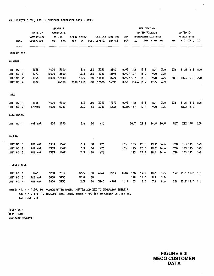
MAUl ELECTRIC CO., LTD. - CUSTOMER GENERATOR DATA - 1993
MAXIMUM PER CENT ON DATE OF NAMEPLATE RATED VOLTAGE RATED KV
COMMERCIAL RATING SPEED RATED GEN.WR2 TURB WR2 GEN NAMEPLATE KVA BASE 10 MVA BASE MECO OPERATION KW KVA RPM KV P.F. LB-FT2 LB-FT2 SCR XD X'D X"D xo XD X'D X"D xo
--------- ------ ------IC&S CO.SYS.
PUUNENE
INIT NO. 1938 4000 5000 2.4 .80 3250 8340 0.95 118 15.8 UNIT NO. 3 19n 10000 12500 13.8 .80 11no 8595 0.907 127 13.0 'INIT NO. 2 1956 10000 12500 11.5 .80 11805 8n4 0.907 127 13.0 INIT NO. 4 1982 24500 3600 13.8 .80 17186 14598 0.58 153.6 16.9
•AlA
UNIT NO. 1 1946 4000 5000 2.3 .80 3250 m9 0.95 118 15.8 'JNIT NO. 2 8/1960 4000 5000 2.3 .80 3200 6363 0.885 137 19.1
PAIA HYDRO
JNIT NO. 1 PRE WAR 800 1000 2.4 .80 (1) 86.7 22.2
:AHEKA
UNIT NO. PRE WAR 1333 1667 2.3 .80 (2) (3) 123 28.8 UNIT NO. 2 PRE WAR 1333 1667 2.3 .80 (2) (3) 123 28.8 JNIT NO. 3 PRE WAR 1333 1667 2.3 .80 (2) 123 28.8
)IONEER MILL
UNIT NO. 1 1966 6250 7812 12.5 .80 6264 7714 0.84 138 14.5 'JNIT NO. 3 PRE WAR 3000 3750 12.0 .80 110 15.0 :JNIT NO. 4 PRE WAR 3000 3750 2.3 .80 3240 4799 1.14 105 8.5
NOTES: (1) H = 1.79, TO INCLUDE WATER WHEEL INERTIA ADD 25% TO GENERATOR INERTIA. (2) H = 0.676, TO INCLUDE WATER WHEEL INERTIA ADD 25% TO GENERATOR INERTIA. (3) 1.12-1.18
GENPP 16-5 APRIL 1989 MGMGEN87.GENDATA
8.4 3.0 236 31.6 16.8 9.0 3.5 9.0 3.5 102 10.4 7.2
11.5 6.9
8.4 3.0 236 31.6 16.8 9.0 4.5 38.2 16.8
14.8 20.0 867 222 148
19.2 24.6 738 173 115 19.2 24.6 738 173 115 19.2 24.6 738 173 115
10.5 3.3 147 15.5 11.2 9.0 3.0 7.0 0.6 280 22.7 18.7
FIGURE 8.31 MECO CUSTOMER
DATA
6.0
2.0
6.0
200
148 148 148
3.5
1.6
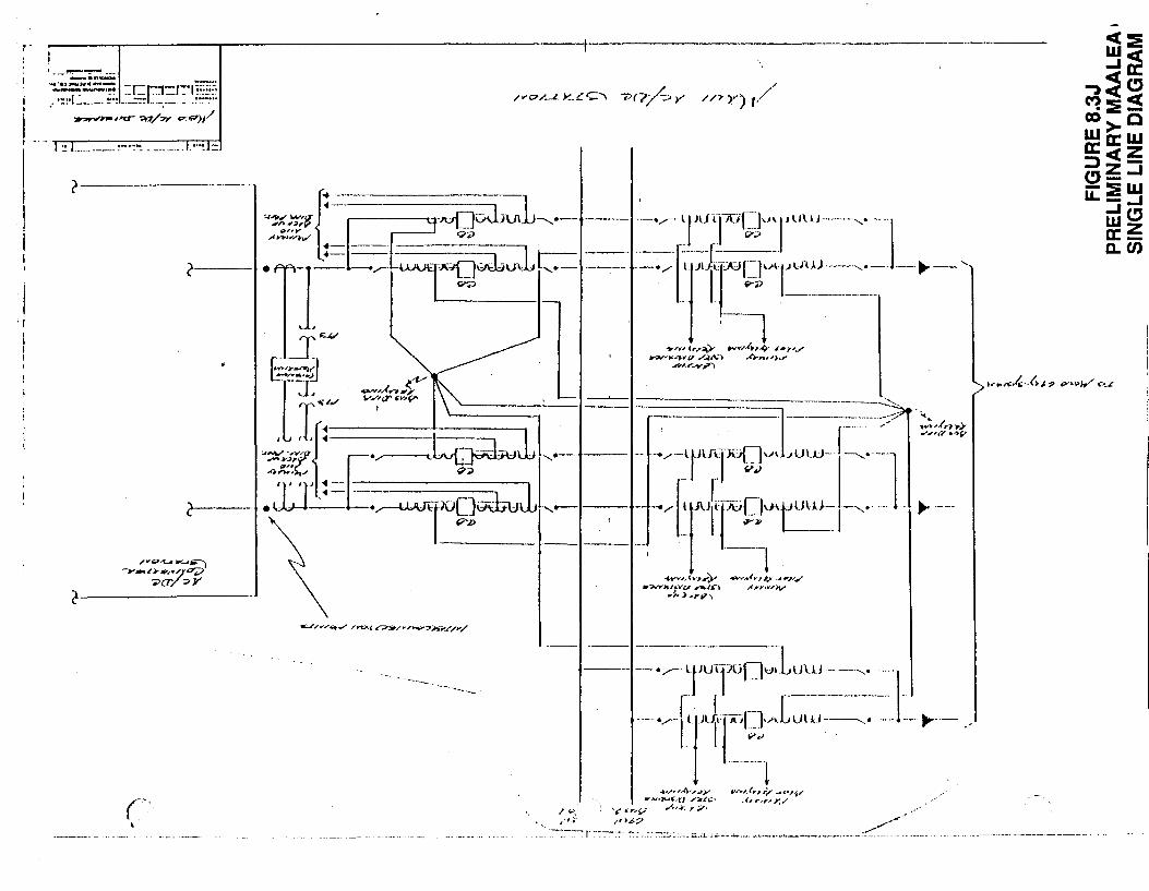
'I
~----~---------,------------------------------------~-------------------------------------
--._... ......... ;;r;~~! -~~r~=~~w.~:
~J"CT ":017/"?' "'-'"')1/
·-······ ---- ·-- ---------
(----------
·---.
r·· '
~ ... < ... ,;,. ~'~'./ ,i,YYir'/;v
-- ---- -------1 --- --•.--L~U\-
1--JUf]v•: UUJ---,. ---··
r . r -- - ·· . . I "'.>
·-----1 •~""'A?.~)/ ,u,,,.(.,~ ,.;,- -""''"'-'1;"
',1 .,.;v·-:::r; :.:;:.~· ~'" ,..,,._. Y."' / ~~ '• '",.. ... v ,-,.~·' ,,),6.? ~/
·_-:--:-:-:~~· ,. ~--~- :·~ ... ::: .. ::.:.:::"::~.;:--~:: • •. ;;;..OL J_.;, ·• .. ..0... ••••• •'· '-'-·•• ...... -..--.-.• ·--·-····-··:~ ·-··
APPENDIX A
GEOTHERMAL RESOURCES OF THE
KILAUEA EAST RIFT ZONE
Prepared from Public Records by
William L. D'Olier
Geothermal Industry Consultant California Registered Geologist, No. 1883
April 1989
00879-1869600-Dl
DISCLAIMER
Neither Hawaiian Electric Company, Stone & Webster Engineering Corporation nor any of the contributors to this document makes any warranty or representation (expressed or implied) with respect to the accuracy, completeness, or usefulness of the information contained in this document. Hawaiian Electric Company and Stone & Webster Engineering Corporation assume no responsibility for liability or damage which may result from the use of any of the information contained in this document.
00879-1869600-Dl
APPENDIX A
GEOTHERMAL RESOURCES OF THE KILAUEA EAST RIFT ZONE
A.l HAWAIIAN ISLANDS - ORIGIN AND ACTIVITY
The island of Hawaii is the newest member of a chain of volcanoes
that have repeatedly matured as major islands in the middle of the
northern Pacific Ocean. An obscure complex of processes is
generating inordinate quantities of magma in a deep earth
phenomena, the mantle plume or mantle hot spot. Within the plume,
at depths of 60 kilometers and more, the Hawaiian basaltic magma
(tholeiite) forms at temperatures of 1350 to 1400°C. These high
temperatures impart an extreme fluidity and density reduction to
the magma. The upward mass movement of magma easily penetrates
the relatively thin oceanic crustal plate and rapidly constructs
new volcanoes on the deep ocean floor (Decker, 1987).
The Hawaiian mantle hot spot, fixed in position and operating as
an energy and mass transfer system for more than 70 million years,
is undeterred by the steady northwestward movement of the Pacific
crustal plate above it. This plate movement has preserved a trail
of older volcanoes and
Chain, which courses
seamounts, The Hawaiian-Emperor Volcanic
straight and west-northwest for 3550
kilometers. After a 60 ° right bend, the chain holds a straight,
north-northwest course for an additional 2600 kilometers before
its destruction, with the Pacific crustal plate, by subduction in
the Aleutian Trench. The 3550 kilometer distance between
currently active volcanic centers (southeastern island of Hawaii)
and the bend represents 44 million years (my) of relatively
continuous and increasing magma production by the Hawaiian hot
spot. The volcanic rock produced, an approximate volume of
750,000 cubic kilometers, now stands on the seafloor as the long,
linear Hawaiian Ridge. The potassium-argon age dates of lava
A-1
00879-1869600-Dl
rocks in the State of Hawaii
respectively, on Nihau and Kauai,
and Mauna Loa, the giant shield
growth studies indicate that the
range from 5.7 to
to 0.375 - 0.4 my at
volcanoes on Hawaii.
Hawaiian hot spot is
5.4 my,
Mauna Kea
Volcanic
presently
generating lava volumes at the greatest eruptive rates in its
known history (Clague & Dalrymple, 1987).
The island of Hawaii is one of the largest volcanic mountains on
the earth. It is a composite structure of five volcanic centers
including the two mighty shield volcanoes Mauna Kea and Mauna Loa.
Often snow covered, these two young peaks stand nearly 4200 meters
above sea level and nearly 9700 meters above the ocean floor in
the Hawaiian
The island's
dimensions of
11 percent of
Trough, a submarine basin northeast of the
land area of 10,438 square kilometers has
150 kilometers N-S and 129 kilometers W-E.
the total volcanic rock mass rises above sea
island.
maximum
Only
level.
Initial lava eruptions on the ocean floor constructed volcanic
seamounts, probably first broaching sequentially as separate
islands, then rapidly coalescing to form the large, young, present
island of Hawaii.
The five volcanic centers on the island of Hawaii, in sequence of
diminishing age, are Kohala, Mauna Kea, Hualalai, Mauna Loa and
Kilauea. The southeastward trends of increasing youth, volcanic
activity and seismicity are even more evident with the inclusion
of the active volcanic seamount, Loihi, 50 kilometers south of
Kilauea's summit caldera with its summit 970 meters below sea
level (see Figure A-1 and Malahoff, 1987). Table A-1 presents key
information on the ages and sequence of volcanic activity at these
six centers.
The magma and lava processes, now operating in their upper dynamic
ranges at Kilauea, repeat the distinctive, comprehensible style of
Hawaiian volcanism. Compared to the worldwide explosive volcanic
events common to both geologic and human history, Hawaiian
A-2
00879-1869600-Dl
II<
~
~
....
volcanism is reasonably well mannered and approachable. This was
implicit in the action of Thomas A. Jagger, (1871-1953) a
Massachusetts Institute of Technology professor, who established
in 1912 the initial scientific facility that was to become the
Hawaiian Volcano Observatory (HVO), at the summit of Kilauea. HVO
has gathered and interpreted an extraordinary body of knowledge
about the mobile magmas and lava that continue to build Kilauea
and the Hawaiian volcanic chain in the mid Pacific. The u.S.
Geological Survey (USGS), having staffed HVO since 1947, has led
this scientific achievement. In 1987, marking the 75th
anniversary of HVO, the USGS published a large, two volume
compendium entitled Volcanism in Hawaii, Professional Paper 1350
(Decker, et al., 1987). There was no intent to examine the
geothermal energy potential of Kilauea amidst the many scientific
objectives of this excellent collection of papers. However, the
papers in Professional Paper 1350 are important supplements to a
thin geothermal drilling and production data base for any
evaluation of .the geothermal resource which exists in the East
Rift Zone of Kilauea. (Professional Paper 1350 may be examined or
purchased at the Earth Science Information Center, USGS, 504
Custom House, 555 Battery Street, San Francisco, CA 94111.
Telephone 415-556-5627.
The vertical magma conduit under the summit of the Kilauea volcano
is the central feature of a vigorous construction process. A
catalog of 70,000 earthquakes, collected by· HVO since 1962,
reveals in substantial detail the active processes of magma
transport within Kilauea's structures (Klein, et al., 1987). Long
period earthquakes trace both conduits and magma bodies rising
from 60 kilometers depths to a shallow magma reservoir between 3
and 7 kilometers below the summit caldera floor. The reservoir is "
aseismic because it stores a relatively large mass of hot liquid
charges of rising magma until an eruptive event is initiated at
the summit or the magma moves laterally into linear rift zones for
further underground distribution. The openings into Kilauea's two
A-3
00879-1869600-01
active rift zones are near the upper limit of its summit magma
reservoir. The solid roof of both the reservoir and the lateral
conduits show varying levels of seismicity which reflects magma
mass and transport at greater depth. The long linear rift zones,
radiating from the summit reservoir, effect a fundamental,
horizontal, internal distribution of magma away from a volcanic
center. A tensional stress field, across the rift zone,
facilitates magma emplacement commonly driven downrift by the
hydrostatic head gained from its brief residence in the summit
reservoir.
' The Hawaiian volcanic rift zones are created as the roofs and
surface expression of active deep magma conduits. Both transient
and locally stored magma masses establish an abundance of thermal
energy. Specifically, . it is the repetitive process of magma
emplacement as near vertical dikes in the tensioned roof rock
which creates the heat source for a geothermal resource potential
in an active rift zone. The Kilauea East Rift Zone (KERZ) is in a
vigorous stage of growth with a geologically optimal level of
internal magma activity. It is flanked by an abundant groundwater
regime on the north and by the sea on the south. The junction of
abundant heat and fluids along the KERZ establishes its unique
geothermal resource potential.
A.2 KILAUEA EAST RIFT ZONE AND ITS GEOTHERMAL RESOURCE POTENTIAL
The topographic form of the KERZ, after its gradual emergence from
Kilauea's gentle summit rise, is that of a broad, linear ridge.
The ridge crest courses east-northeast and straight for 42
kilometers, from an elevation of 880 meters at Makaopuhi Crater to
sea level at Cape Kumukahi (see Figure A-2). Beyond the Cape, the
submarine element of the KERZ carries the same straight course for
an additional 70 kilometers to termination on the ocean floor at
an approximate depth of 4,800 meters. The entire structure,
subaerial and submarine, was built rapidly by repeated rift crest
A-4
00879-1869600-Dl
lava eruptions supplied by magma transport in the underlying
conduit. In the middle of the subaerial element the lava apron
has a maximum topographic width of 18 kilometers measured normal
to the rift axis. The more significant feature of the KERZ is the
crestal band of local volcanic cones, craters, linear fissures and
graben fault structures that reflect the crestal, cross rift,
tensional stress above the deep magma conduit. The surface width
of this active band is approximately 3 kilometers.
In 1976, at a location approximately 10.5 kilometers uprift from
Cape Kumukahi and on the active crest of the KERZ, the initial
geothermal test well, HGP-A, was drilled to a total depth of 1966
meters. A bottom hole temperature of 358°C was encountered and a
total mass flow rate of 110,000 pounds per hour, 43 percent steam
and 57 percent liquid, was measured. Following installation of a
3 MW turbine generator in March 1982, the steam production of this
initial well has provided electric power in the range of 2.8 to 2
MW. Except for scheduled overhauls, this small geothermal power
plant has operated continuously for seven years with an
availability factor of approximately 90 percent. The geothermal
fluid and electrical production from this single well and plant,
now called
detail in
the HGP-A Generator Facility, is discussed in more
achievement provides the most Section A.S. This
meaningful indication of an exploitable geothermal resource in the
KERZ.
The internal fabric of fast-building Hawaiian rift zones is a
nearly horizontal, planar sequence of submarine and subaerial lava
flows. These basaltic flows originate from local volcanic vents
or parallel linear fissures situated along the rift crest
over lying the deep magma conduit. In the upper part of the KERZ
the top of the magma conduit appears to be shallower (seismicity
to 2-3 kilometers) and consistently open (deeper aseismic zone) as
discussed in Hardee, 1987. The continuous lava eruption which
began in January 1983 in the upper KERZ, is now venting from a
A-5
00879-1869600-Dl
newly constructed volcanic cone, C48, at a point approximately 10
kilometers down rift from Makaopuhi Crater. The lava flows are '"'
spilling southeastward and into the sea between Kupapau and Hakuma
Points.
In the lower 30 kilometers of the KERZ the top of the magma
conduit appears to be deeper (about 3. 4 kilometers or more) and
more commonly closed. Here, the advancing magma reopens conduits
by the hydraulic injection capability of its significant fluid
pressure. The existing host rock is penetrated by the mobile
fluid magma in nearly vertical planar sheets, several feet thick.
Both thermal energy and high temperatures are maintained by
repetitive dike intrusion and solidification. This dike building
process is facilitated by the tensional stress imposed on the rift
crest, from magma conduit depths to the surface, by earthquakes,
normal faulting and slumping of the seaward south flank of the
KERZ. Dike emplacement in the lower KERZ efficiently transfers
high heat quantities from magma to shallower prospective
geothermal reservoir intervals, as shown in Figure A-3.
Because Hawaii geothermal drilling records, required to be filed
with the State of Hawaii Department of Land and Natural Resources
(DLNR), are reported in English units, the following discussion
will utilize the same. The productive geothermal well HGP-A has a
7 inch perforated liner completion in the depth interval between
2920 and 6450 feet. This interval of submarine lava flows and
younger intrusive dike rock presented a temperature profile that
increased to approximately 620°F at 4000 feet, decreased to about
570°F at 5800 feet and increased to a maximum 676°F at 6450-foot
total depth (see Figure A-4). The selection of the top of the
geothermal reservoir (and completion) interval in this first well
seems debatable. A restriction in the liner, just above 4000
feet, unfortunately precludes a spinner evaluation of the deep
fluid entries in HGP-A. Aside from these concerns, this well
A-6
00879-1869600-Dl
continues to produce geothermal reservoir fluids with little
decline since it was put into production in December 1981.
Puna Geothermal Venture (PGV) during 1981-85 drilled three offset
wells (about 1800 and 3500 feet away from HGP-A well). In a
publicly distributed November 1987 Environmental Impact Statement
(EIS) for a proposed 25 MW (net) geothermal power plant and
wellfield, PGV states the geothermal reservoir extends below 4000
feet. PGV bottomed these offset wells at total depths between
7300 and 8000 feet. The EIS briefly characterizes the geothermal
reservoir as "very high temperature (over 600°F), two-phase
(vapor-liquid)". Higher steam fractions were obtained in all PGV
initial flow tests than the 43 percent steam fraction long
prevailing in the HGP-A well production. From these four wells
which have produced or tested geothermal fluids, the geothermal
resource, in the Kapoho locale of the lower KERZ, is a 600°F,
two-phase regime at moderate depth. Three additional exploratory
geothermal wells drilled along the south edge of the KERZ crestal
structure have encountered encouraging temperatures but have not
demonstrated fluid yielding reservoir intervals by flow tests.
These seven deep geothermal wells are discussed in more detail in
Section A.5 following.
DLNR, under its published Rules on Leasing and Drilling of
Geothermal Resources, requires the filing of certain well reports
(513-183-85) following completion of drilling operations on any
geothermal well. After an initial period of confidential status,
these well records are opened to public access. The reports of
all seven of the geothermal wells drilled in the lower KERZ may
now be copied or examined at the public document room.
Significant documents include well drilling and completion
histories, lithologic and temperature logs, some geophysical logs
and water sample analyses.
A-7
00879-1869600-Dl
A hypothetical geothermal reservoir would be expected to be
located in the tension stressed, fractured rock below the crestal
band of the KERZ as shown in cross section in Figure A-5. The
moderately deep vertical extent of the reservoir would be
positioned in the hot diked roof above a deeper bundle of magma
conduits or a possible static magma body. Penetrations of copious
supplies of fresh groundwater, and of seawater to a lesser extent,
would enter at depth from opposing boundaries of the fractured
reservoir to mix in an internal convection cell with a base
temperature of 600°F. The cross rift and long rift extent and the
specific nature of the effective side boundaries of the
hypothetical reservoir have yet to be determined. Drilling along
the south flank of the KERZ crest suggests that sharp vertical
boundaries exist there.
Subsurface supplies of waters that would contribute to KERZ
geothermal regimes are inferred to be large. The two shield
volcanoes, Mauna Kea and Mauna Loa draw heavy precipitation from
the northeast trade winds. Annual rainfall of 100 to 125 inches
is received on the lower slopes of Mauna Loa and the crest of the
KERZ. Practically all of this sinks into the porous surface lavas
and this meteoric water infiltration has established a very large
ground-water body along the whole north flank of the KERZ. A
limitless supply of seawater can infiltrate the entire narrow
southern flank.
In spite of the paucity of specific hydrologic subsurface data,
several early findings suggest that interactions between
groundwater, geothermal fluids and seawater will be intricate. A
small group of private water wells, drilled on the lower KERZ
before its geothermal potential was perceived, were never utilized
because of the poor quality of the abundant shallow groundwater
found. This has recently been identified as natural degradation
caused by leakage from the now proven geothermal reservoir
(Iovenitti, 1987). In the produced liquid fraction from the HGP-A
A-8
00879-1869600-Dl
well, the sodium to chloride ratio within the steadily increasing
total dissolved solids content indicates seawater intrusion into
the geothermal reservoir. A preliminary working concept of large
fresh water and seawater supplies aggressively penetrating the
prospective geothermal core of the KERZ and contributing to the
hot fluid convection is sketched in Figure A-5.
A.J LEGAL STATUS AND REGULATION OF GEOTHERMAL RESOURCES
Ownership of geothermal resources is claimed by the State of
Hawaii under state lands and under Reserved lands. The latter are
lands owned or leased by any person in which the State or its
predecessors in interest has reserved to itself, expressly or by
implication, the minerals or right to mine minerals, or both.
Most private land ownerships in the KERZ are Reserved lands.
Certain private land owners may eventually choose to test in the
courts the State's claim to geothermal resource ownership related
to the Reserved land concept. All geothermal resource development
commonly will require dual leases on the Reserved land tracts to
be utilized. A geothermal mining lease must be obtained from the
State for the subsurface rights to the geothermal resource and a
lease must be obtained from the landowner for surface access and
utilization. DLNR administers geothermal leasing and drilling
under rules in Title 13, Chapter 183, which were approved in June
1981. Key State geothermal leasing provisions are royalties of 10
to 20 percent on resources produced, sold, or utilized. When
necessary to initiate or continue commercial production of
geothermal resources, the State Board of Land and Natural
Resources (BLNR) is authorized to waive royalty payments to the
State for any period up to eight years. Ten year primary terms of
leases are extendable to a total of 65 years. Individual lease
tracts are limited to 5000 acres of contiguous lands. State lands
are leased by public auction only, and Reserved lands are leased
by grant to the landowner or by auction. Hawaiian land ownership
tracts, highly varied in size and in shape, are legally
A-9
00879-1869600-Dl
represented by Tax Key Maps. Land corner monuments and surveys of
the highly varied tracts have not been commonly utilized.
Haw~ii has stringent land use laws (see Hawaii Revised Statutes
205) which, when enacted, did not address geothermal resource
utilizations. The BLNR and the counties jointly establish and
regulate land use districts which are dedicated to urban, rural,
agricultural and conservation uses. In 19 84, state regulations
were amended to enable geothermal development in all land use
districts provided a Geothermal Resource Subzone (GRS) was first
established by procedures under Title 13, Chapter 184. The BLNR •
was given the authority to designate and regulate GRS. Three GRS
were approved and established in the KERZ as shown in Figure A-6.
The total amount of lands included are approximately 21,900 acres
apportioned among three blocks as follows:
Kilauea Lower East Rift (Kapaho Section)
Kilauea Lower East Rift (Kamaili Section)
Kilauea Middle East Rift
7,353 acres
5,531 acres
9,014 acres
Geothermal development may proceed only within such designated GRS
areas. Proposed designations of new GRS may be initiated by the
BLNR, any landowner, geothermal lessee or lease applicant, as can
proposed modifications and withdrawals of existing GRS.
Environmental impact statements are not required in designating,
modifying or withdrawing any GRS. The GRS process has structured
the deliberations about possible geothermal resource utilizations
and has interfaced the county and state authorities within
designated GRS areas of the KERZ. Hawaii County is the lead
authority if exploration or development is proposed on rural and
agricultural lands within the GRS. DLNR is the lead authority on
conservation lands within the GRS. It must be noted that public
input to the GRS process is significant. Until the value of
geothermal enterprise is more clearly demonstrated, resistance to
GRS enlargement in the KERZ is expected.
A-10
00879-1869600-Dl
The approval paths for exploratory geothermal drilling on dual
surface and subsurface (state) leases within GRS are briefly cited
here because this is the critical, near term activity required in
the KERZ. Permit requirements in the Geothermal Resource Subzones
are detailed in Appendix B. On agricultural and rural lands a
Geothermal Resource Permit (special use permit) must be approved
under Rule 12 by the Hawaii County Planning Commission. On
conservation lands, a Plan of Operation and a Conservation
District Use Permit must be approved by DLNR. Individual drilling
permits for each proposed geothermal well are required from DLNR
regardless of the land use classification of the drillsite.
A.4 AVAILABILITY AND ACCESSIBILITY; PROSPECTIVE AREAS
The three designated GRS areas in the lower KERZ cover a
substantial portion of the prospective crestal trend which extends
for approximately 30 kilometers between the C48 erupting volcanic
vent and Cape Kumukahi. DLNR records of issued geothermal mining
leases and applications for lease now cover a substantial portion
of the GRS areas. Several of the large landowners in the KERZ are
lessees under issued geothermal mining leases. Kapoho Land and
Development Company, Bishop Estate and the Campbell Estate are
landowners with geothermal leases or applications dedicated to
existing exploration or development agreements with certain
geothermal operators. Other privately owned land tracts within the GRS areas are, or may be, under lease or option agreements with geothermal operators. Such leases may or may not coincide
with issued mining leases and may or may not be disclosed in
public records.
HECO and its consultanJs made no inquiries or evaluations of
landowner and leaseholder positions in contemplating or
structuring this RFP. Landowners, leaseholders and geothermal
operators positioned in the KERZ will determine their individual
responses to this RFP. Proposers are cautioned that they proceed
A-ll
00879-1869600-Dl
at their full risk in evaluating and responding to the status of
lands and leases in the KERZ.
Off-road accessibility in most of the KERZ terrain is difficult to
impossible, even for four wheel drive vehicles. Dense
undergrowth, forest cover and impassable lava rock sur faces are
typical barriers. Most private land tracts are fenced or posted
against trespassing. New road construction approvals for
geothermal development will be keyed to the status. of the land
traversed: agricultural, rural or conservation.
A.S ELECTRIC GENERATION AND RESOURCE PRODUCTION IN THE KERZ
The 3 MW
constructed
Department
profile of
power plant of the
in 1981 with funds
of Energy, the State
the plant's electric
HGP-A Generator Facility was
jointly provided by the u.s. and the County of Hawaii. A
generation history is shown in
Figure A-7 for the seven year interval, commencing in March 1982,
of commercial power delivery to Hawaii Electric Light Company.
Because of economic constraints, detailed well production records
were not accumulated. Possible declines in wellbore
deliverability or reservoir performance might be inferred from
generator outputs; an initial peak output of 2.8 MW versus 2.45 MW
currently suggest a 1.8 percent annual decline in well production.
Although several scheduled overhauls were made without finding
serious degradation, certain rna ter ial and equiprnen t def ic i enc i es
in plant design have been clearly demonstrated and may be
registered in the output decline. Cumulative silica scaling in
the HGP-A wellbore may be a contributing cause of the apparent
decline. Several very informative studies of plant and well
performance have been completed and documented in recent years by
Donald Thomas of the Hawaii Insitute of Geophysics.
The continuous 7-year geothermal fluid production of the HGP-A
well has been very successfully utilized. However, it has
A-12
00879-1869600-Dl
.lj!>'
afforded only a meager basis for understanding the geothermal
resource. The lack of detailed records of fluid production
parameters, of periodic pressure-temperature-spinner surveys over
the well's 3530-foot perforated liner completion interval and of
reservoir pressure monitoring in any offset observation hole are
to be noted. This provides little context within which several
perceptive and thorough studies of produced fluids chemistry can
be conclusively judged {Thomas 1985a and 1987).
The total mass flow of HGP-A well, measured initially as
approximately 47,300 pounds per hour steam and 62,700 pounds per
hour liquid, is a product of wellbore mixing {inside 7 inch
production casing) of different fluids from multiple, separate
entry points of imprecise depths, pressures and temperatures. The
distinctive, low salinity of the first produced liquid, suggestive
of a meteoric water dominance in the geothermal reservoir, was
lost in a gradual, four-year increase in salinity, to about 15,000
mg/kg of NaCl, with production for electric generation. The Na
and Cl ionic ratios and other metallic changes seem to prove a
seawater intrusion into HGP-A well's production sink. This fluid
change to a new high but stable, level of salinity appears to
confirm the implications of an irregular presence of anhydrite
filled fractures amidst other alteration minerals found in the
HGP-A rock cores from the reservoir interval. Fracture guided
intrusions of seawater into the geothermal fluid convection cells
must repeatedly occur. However, these intrusions individually are
probably limited in duration and volume because of rapid
self-sealing by new mineral deposition at the seawater-geothermal
fluid interface. A diminution of pH from 7. 6 to 6. 5, at tending
the increase in salinity of produced brines, was measured.
Possible minor decreases in produced steam fraction and wellhead
temperature, if suspected from time to time in short term flow
variations, have not been measured to identify any long term
trend. The precisely identified stability of the silica content
of the brine {about 800 mg/kg) and of the low content of
A-13
00879-1869600-01
non-condensible gas ( 0. 3 percent by weight) in the steam phase
reflect the apparent stability of the total mass flow produced by
the HGP-A well since December 1981.
Key information from the seven deep geothermal wells drilled into
the geothermal reservoir, or equivalent depths, in the lower KERZ
is summarized in Table A-2. Their locations are shown on Figure
A-6.
Key features of the wells which penetrated the geothermal
reservoir were 9 5/8 inch production casing (cemented just below
4000-feet in KS wells) and 7 inch perforated liner in an
8 1/2 inch hole to total depth. It should be noted that both
HGP-A and KS-1 wells include remedial 7 inch casing inserts that
were emplaced before production and testing. The KS 1 and 2 tests
support the recent conclusion (Thomas, 1987) that a dry steam
producing zone exists in the HGP-A well. Composite chemical data
from the four wells tested are presented in Tables A-3 and A-4.
Final Hawaii County approvals are being sought for the Geothermal
Resource Fermi t for the PGV' s proposed 2 5 MW (net) geothermal
plant and wellfield which expectedly will include KS-lA and 2
wells in production service. Drilling plans for the required
additional production and injection well are in preparation for a
commencement of development operations later in 1989.
A proposed Scientific Observation Hole Program at additional •
locations within the GRS areas along the lower KERZ is planned.
The intended slim hole drilling program, utilizing both rotary and
diamond core procedures, is jointly funded by the State of Hawaii
and geothermal operators (Geothermal Resources Council Bulletin,
1988). Information from the intended 4000-foot holes is to be
promptly released to the public domain and should be available
during the negotiation period for the Power Purchase Agreement.
A-14
00879-1869600-Dl
A.6 GEOTHERMAL RESERVOIR POTENTIAL IN THE KERZ
The geothermal reservoir potential of the KERZ is most strongly
supported by the HGP-A Generator Facility performance combined
with its position above a magma conduit which is reasonably
defined as to location and function. The critical concern is an
estimate of the magnitude of this reservoir potential within the
lower KERZ between the C48 vent and Cape Kumakahi (30 kilometers
or 18.6 miles).
Volcanic eruptive history proves recurring magma transport through
the entire lower KERZ. Significant lava eruptions from~
Heiheiahulu "in the reign of Arapai" - circa 1750 A.D. (vent is 22
kilometers SW of Cape Kumakahi) and the Kapoho eruptions of 1955
and 1960 obtain importance against a detailed modern study of
Kilauea's magma balance. The USGS - HVO concludes that nearly 50
percent of all magma mass remains below ground, being emplaced as
intrusive dikes and sills. The entire KERZ has become a more
magma distribution and dike construction
7.2 Kalapana earthquake of 1975 which
entire KERZ structure by seaward slumping
favored structure for
since the magnitude
tensionally opened the
of its south flank, as shown in Figure A-8 and discussed by
Lipman, et al., 1987. A preliminary estimate, made from
deflations of Kilauea's summit following the 1975 quake, was that
3 million cubic meters per month of magma was moving into the rift
zones. The deep fracturing in the KERZ consequent to this major
earthquake should enlarge or maintain reservoir permeability and
new meteoric and seawater inputs to geothermal fluid convection
cells. Heat, fractures and fluids are renewed in the dynamic,
continuous structure above the KERZ magma conduit.
The 500 MW objective of this RFP is based on market considerations
(Lesperance, 1988, and Department of Business and Economic
Development, 1989). No integrated study exists of all the KERZ
geoscientific and well data that would provide a creditable
A-15
00879-1869600-Dl
estimate of the total geothermal potential. Only additional
drilling, flow testing and production can provide measures of the
energy capacity that is indicated to exist in the GRS of the KERZ.
It is of some interest to note that one existing developer intends
to utilize a 500 acre land area dedicated to its 25 MW (net)
generation capacity. This suggests that the 22,000 acres within
the three GRS areas, if only 50 percent productive, could yield
550 MW of capacity.
A.7 GASEOUS AND LIQUID WASTE DISPOSAL FROM GEOTHERMAL WELLFIELD ACTIVITIES
Effluent waste disposal from the producing HGP-A well has not been
managed in a way that is acceptable for future geothermal
development in the KERZ. The 57 percent brine fraction, carrying
about 15,000 mg/kg of NaCl and 800 mg/kg of Si0 2 , is discharged to
shallow surface ponds for percolation into the ground. The
attending silica deposition eventually precludes percolation and
new ponded areas are then utilized. This practice is unacceptable
for the future corrunercial development that will occur along the
KERZ. The produced non-condensible gas ( NCG) is burdened with
about 850 mg/kg of H2 S. Normal plant operation produces 1100
pounds per day of H2 S that is now abated, with reasonable
reliability, with NaOH in a two stage scrubber and by
incineration. The H2 S abatement experience at HGP-A, although
costly and problem-plagued, provides notice that reliability, -
reserve capacity and alternate options of H2 S mitigation will be
essential to successful "good neighbor" geothermal development in
the KERZ. It is appropriate to note that PGV's Amended
Application for Geothermal Resources Permit for 25 MW (net) Plant
and Wellfield (December 1988 submittal to Hawaii County Planning
~Department) proposes the injection of recombined streams of brine,
condensate and NCG back into the geothermal reservoir. Just such
recombined fluid injection reportedly is successful in its first
year of utilization in the Coso geothermal field in California.
A-16
00879-1869600-01

The present status of H2 S emission controls, regarding geothermal
development in the KERZ, merits special attention. A 1982-1983
State survey of H2 S levels in a 27 station KERZ grid was
completed, as were local surveys by HGP-A and PGV. These surveys
should provide some insight into natural H2 S emissions from
continuous volcanic gas venting that proceeds between the obvious
eruptive events. Aside from this singular feature of the KERZ,
the Hawaii Department of Health (DOH), as the State regulatory
authority, is now proposing a statewide ambient 1-hour emission
standard of 139 micrograms H2 S per cubic meter ( 0.1 ppmv) for
inclusion in Administrative Rules Chapter 11-59. DOH also
proposes a statewide allowable increment of 0.35 mg/m 3 (0.35 ppmv)
of H2 S emission from any new facility. This proposal and lesser
H2 S constraints are included in draft DOH Rules 11-60-15 and 16.
An additional DOH regulatory authority extends statewide to
underground injection control (UIC). Though the non-potable
quality of ground water was proven by landowner drilling in the
KERZ before recognition of the geothermal resource, some of the
GRS areas remain in the Underground Sources of Dr inking Water
(USDW) status. Injection of produced geothermal fluids will
require approval by the DOH.
A.8 VOLCANIC AND SEISMIC IMPACTS ON WELLFIELD DEVELOPMENT
An excellent summary of the volcanic hazards that occur along the
KERZ is presented by Mullineaux, et al. 1987. Lava flows will
pose the most likely hazard over time, as shown in Figure A-9.
However, lava flows are controlled by topography, as any surface
water flow would be. A careful evaluation of the KERZ terrain can
be made with the assistance of detailed topographic maps recently
published by the USGS (1:24,000 scale and 20-foot contour
interval). The probable flow course and other possible
topographic controls can be reasonably predicted. The morphology
and emplacement dynamics of the blocky aa type of lava flow are
A-17
00879-1869600-Dl
detailed by Lipman and Banks, 1987. This more viscous, thicker
building flow commonly moves in a 100-200 meter frontal width,
several meters high and at velocities up to SO meters per hour.
Final flow thickness may range from 5 to 10 meters in height.
The less likely but more serious volcanic hazard, the fissure or
vent eruption site event, is mitigated by the much smaller area of
direct impact. However, against the expected long life of the
geothermal resource it cannot be considered predictable in time or
location. It will remain the greatest risk in development of the
geothermal resources of the KERZ. Air lofted tephra (rock debris)
ash and gas concentrations from eruptions may yield a range of
secondary and addressable impacts on any KERZ geothermal site
depending on wind conditions and distance from source points.
Ground surface dilation, extension or subsidence due to local
magma movements or lava discharges, are additional processes
common in the KERZ that are of minor impact on wellfield
operations.
The high seismicity of the KERZ is directly cor related with its
high level of constructional volcanic activity. This is clearly
presented in an excellent new map publication of statewide scope:
"Seismicity of Hawaii, 1962-1985, USGS Open File Report 88-285"
which may be purchased at the Pacific Map Center, 647 Auahi
Street, Honolulu, HI 96813, Telephone 808-531-3800. The
seismicity of Kilauea's magma system, detailed by Klein, et al.,
1987, chiefly includes events of less than magnitude 4 which are
generated by magma and dike activity in the 2-5 kilometers depth
interval. This class of seismicity presents a significant guide
for geothermal wellfield development and presents little or no
attendant hazards. It is the deep, infrequent, tectonic
earthquakes of magnitudes ± 7 which could impact KERZ geothermal
development. Fortunately, the largest historical earthquake in
this class, the November 1975 magnitude 7.2 event, at a depth of 9
kilometers under Kalapana on the southeast coast of the Island of
A-18
00879-1869600-Dl
Hawaii, was fully recorded by the HVO seismic network. This
imposed a 0.22 gravity acceleration measured at Hilo
( 43 kilometers NNW of Kalapana) . Geothermal wells in the KERZ,
with multiple cemented casing strings and Series 900 wellheads,
spider braced in reinforced concrete cellars, should surpass the
0.4 gravity acceleration factor selected for the plant and surface
facility design to safely withstand the tectonic class of
earthquake.
Significant strategies can be utilized for the protection of KERZ
geothermal wellfield development and production operations.
Directional drilling would permit wellheads to be clustered on
elevated or cinder berm protected wellpads that would be at
minimal risk from both volcanic and the seismic hazards. Drilling
rigs may merit heavier guy-lines as added protection. Steam and
other wellfield pipelines will be vulnerable to lava flows and to
major earthquakes. Rapid cinder berm construction and pipeline
repair capacities can be considered as response options.
The common volcanic-seismic basis of both the resource and hazards
in the KERZ should. encourage development of key surveillance
methods. A very sensitive seismic net could simultaneously
forecast possible lava eruptions and track the wellf ield
production and injection fluid impacts to optimize geothermal
reservoir management. Multiple physical and chemical parameters
can be examined for volcanic-seismic-exploitation correlations
that may increase thermal energy recovery and reduce the attendent
risks.
A.9 GEOTHERMAL WELLS AND WELLFIELD CONCEPTS AND OPTIONS
The important tasks in future geothermal drilling in the KERZ will
be to increase well productivity and reduce well costs. An early
evaluation of directed, angled completion intervals seems
appropriate, given the common feature of near vertical and planar
A-19
00879-1869600-Dl
fractures, partings and dikes parallel to the rift axis, in the
expected production intervals. The four penetrations of the fluid
yielding reservoir to date were in vertical well bores, which is
less than an optimal orientation to intercept near vertical
openings. If an upper reservoir yield of 100 percent steam
production could be achieved by more precise completions, possibly
in the 4000 to 6000 foot depth interval as suggested in the KS
wells, a productivity increase and associated cost reduction might
significantly assist initial wellfield development. This finding
would next invite consideration of "big hole" production wells.
In the context of improving well productivity and accurately
measuring the results, it is important to note that initial well
flow testing of KERZ geothermal wells is not a simple and low cost
task (D'Olier and Iovenitti, 1984). The presence of cool
groundwater aquifers to possible depths of about 2000 feet calls
for gradual preparations. An initial static warmup (first
geothermal fluids rising within the completion fluid column of the
shut-in well) followed by accelerated heating and deliberate
bleeding will elevate the wellbore to a more uniform thermal state
to accommodate the initial high mass - high temperature flow upon
opening. The capacity to go promptly to fully opened, vertically
vented flow to atmosphere must be present because of an extremely
erosive initial discharge of a sharp grit of rock and minerals
from the producing formation. A continuous, full open flow, with
its 120 decibel noise penalty, appears to be the most efficient,
fast and safe procedure to obtain this critical well cleanup
before shunting the flow into measurement runs and muffled
venting.
As waste fluid injection is thoroughly evaluated and is considered
for high utilization in the KERZ, the function and reliability of
injection wells will become as critical to system operations as
production wells are. Expecting a design and quality comparable
to production wells, injectors must be further protected with a
A-20
00879-1869600-Dl
""'
hang down casing string (replaceable) as the injectate conduit to
the perforated linered interval at depth. Actually, marginal
production wells may be placed on back up injection service with
the addition of a protective hang down string. It appears that
accurate and detailed knowledge of geothermal reservoir
performance and optimal utilization of every well will be
essential in the KERZ.
A.lO MATURITY OF TECHNOLOGY
The improvement of geothermal well design and material selection
will be important considerations for economic development of KERZ
reservoirs. The conventional design and K-55 grade of casing and
liner used in the HGP-A well seems to be endorsed by more than
seven years of continuous production. However, the down hole
conditions of this wellbore are poorly known. The costs of the
offset wells, at industry market rates in the early 1980's,
commonly exceeded $2,000,000 per well for drilling and completion.
Substantial improvements in logistics and management of future
development drilling should be important cost reduction factors.
Upgrades in tubular materials, couplings, and possible cementing
in tension procedures may provide gains on a benefit-to-cost
basis. Modern rotary drilling, cementing and drilling fluid
practices are mature practices that should serve efficiently in
KERZ geothermal wellfields. ANSI 900 series wellhead equipment is
indicated for standard utilization on KERZ production wells.
The production of two-phase fluid production and 100 percent steam
production are mature geothermal industry technologies. High
volume liquid injection into a producing geothermal reservoir is a
developing technology in the industry. Injection into KERZ
reservoirs may prove difficult to integrate with the production
objectives; an alternate injection disposal target may be deep
seawater zones immediately south of the expected geothermal
reservoirs.
A-21
00879-1869600-Dl
The substantial daily fluctuation of the Oahu power requirements
indicates that PROPOSERS should consider a load-following, daily
cycling of KERZ geothermal wellfield production as one option
among other possible responses. Daily cycling in the form of a
shared reduction of steam supply, from a wellfield sector
producing commonly to one generating plant, is not known to be a
sustained practice anywhere in the geothermal industry at this
time. The required reduction alternatively might be achieved by a
nightly shut-in of a much smaller number of wells. The impacts of
a common nightly reduct ion, or of a selected (or rota ted) full
shut-in, will relate to the magnitude of pressure and temperature
increases imposed in each wellbore, wellhead and flow control
valve and to the endurance or quality of well design, materials
and equipment. All of these factors will be site specific to the
geothermal reservoirs, producing wells and economics to be en
countered in the KERZ.
A.ll OPERATIONS AND MAINTENANCE
Replacement (makeup} well drilling, redrilling for extended or
improved production or injection service, and remedial cleanouts
may become significant requirements in KERZ geothermal fields. No
other extraordinary requirements are indicated.
A.l2 REFERENCES FOR APPENDIX A
Bell, D. and Thomas, D.M., October, 1988. Report on the October,
1987 Hawaiian HGP-A Power Plant Overhaul and Reservoir Production
Data, in Geothermal Resources Council Transactions.
343.
Vol. 12, p.
Clague, D.A. and Dalrymple, G.B., 1987. The Hawaiian-Emperor
Volcanic Chain, in u.s. Geological Survey Professional Paper 1350,
p. 5.
A-22
00879-1869600-Dl
-
Decker, R.W., 1987, Dynamics of Hawaiian Volcanoes: An Overview,
in U.S. Geological Survey Professional Paper 1350, p. 997.
Decker, R.W., Wright, T.L. and Stauffer, P.H., Editors, 1987.
Volcanism in Hawaii, U.S. Geological Survey Professional Paper
1350, Volumes 1 and 2.
Department of Business and Economic Development, 1989.
Environmental Review, 500 MW Geothermal Development within the
Three Geothermal Resource Subzones of the Kilauea East Rift Zone,
Puna District, Island of Hawaii. March, 1989.
D'Olier, W.L. and Iovenitti, J.L., 1984. Drilling and Testing
Geothermal Wells in an Active Volcanic Domain, Puna Geothermal
Field, Hawaii, USA, in Proceedings, ASEAN Geothermal Workshop,
Banding, Indonesia, May 1984.
Geothermal Resources Council Bulletin, November, 1988, Funds
Appropriated for Resource Assessment in Hawaii, p. 12.
Hardee, H.C., 1987. Heat and Mass Transport in the East-Rift
Zone Magma Conduit of Kilauea Volcano, in U.S. Geological Survey
Professional Paper 1350, p. 1471.
Iovenitti, J.L., 1987. Geothermal Fluid Leakage, Lower East Rift
Zone Kilauea Volcano, Hawaii, in Abstract Volume and Poster
Session, Hawaii Symposium on How Volcanoes Work, HVO 75th
Anniversary, Hilo, Hawaii, January, 1987.
Iovenitti, J.L. and D'Olier, W.L., 1985. Preliminary Results of
Drilling and Testing in the Puna Geothermal System. Hawaii, in
Proceedings, Tenth Workshop, Geothermal Reservoir Engineering,
Stanford University, January, 1985.
A-23
00879-1869600-Dl

Klein, F.W., Koyanagi, R. Y., Nakata, J .S., and Fanigawa, W.R.,
1987. The Seismicity on Kilauea's Magma System, in U.S.
Geological Survey Professional Paper 1350, p. 1019.
Lesperance, G.O., October, 1988, Geothermal Development in Hawaii,
in Geothermal Resources Council Transactions, Vol. 12, p. 75.
Lipman, P.W. and Banks, N.G. 1987, AA Flow Dynamics, Mauna Loa
1984, in U.S. Geological Survey Professional Paper 1350, p. 1527.
Lipman, P.W., Lockwood, J.P., Okamura, R.T., Swanson, D.A., and
Yamashita, K.M., 1985, Ground Deformation Associated with the 1975
Magnitude- 7.2 Earthquake and Resulting Changes in Activity of
Kilauea Volcano. Hawaii: U.S. Geological Survey Professional
Paper 1276. 45 pages.
Malahoff, A. 1987, Geology of the Summit of Loihi Submarine
Volcano, in U.S. Geological Survey Professional Paper 1350, p. •
133.
Mullineaux, D.R., Peterson, D.W. and Crandell, D.R. 1984,
Volcanic Hazards in the Hawaiian Islands, in U.S. Geological
Survey, Professional Paper 1350, p. 599.
Thomas, D.M., l985a, HGP-A Well Chemistry in Chemistry, Scale and
Performance of the Hawaii Geothermal Project - A Plant, Electric
Power Research Institute AP-4342, Project 1195-12, Final Report.
Thomas, D.M., 198Sb, The HGP-A Generator Facility, Reservoir
Character is tics and Operating History, in Proceedings, Electric
Power Research Institute, Geothermal Workshop, 1985.
Thomas, D.M., 1987, A Geochemical Model of the Kilauea East Rift
Zone, in U.S. Geological Survey Professional Paper 1350, p. 1507. •
A-24
00879-1869600-Dl
Thomas, D.M. and Olson, H.J., 1989, Current Status and Future
Research Objectives for the HGP-A Generator Facility, in
Proceedings, Fourteenth Workshop, Geothermal Reservoir Engine
ering, Stanford University, January, 1989 (in press).
A-25
00879-1869600-Dl
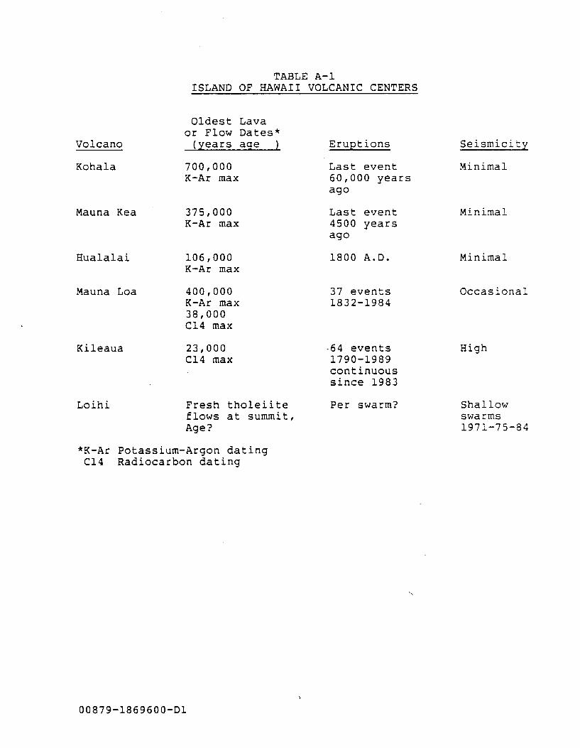
TABLE A-1 ISLAND OF HAWAII VOLCANIC CENTERS
Volcano
Kohala
Mauna Kea
Hualalai
Mauna Loa
Kileaua
Loihi
Oldest Lava or Flow Dates*
(years age )
700,000 K-Ar max
375,000 K-Ar max
106,000 K-Ar max
400,000 K-Ar max 38,000 Cl4 max
23,000 Cl4 max
Fresh tholeiite flows at summit, Age?
*K-Ar Potassium-Argon dating C14 Radiocarbon dating
00879-1869600-D1
Eruptions
Last event 60,000 years ago
Last event 4500 years ago
1800 A.D.
37 events 1832-1984
-64 events 1790-1989 continuous since 1983
Per swarm?
Seismicity
Minimal
Minimal
Minimal
Occasional
High
Shallow swarms 1971-75-84
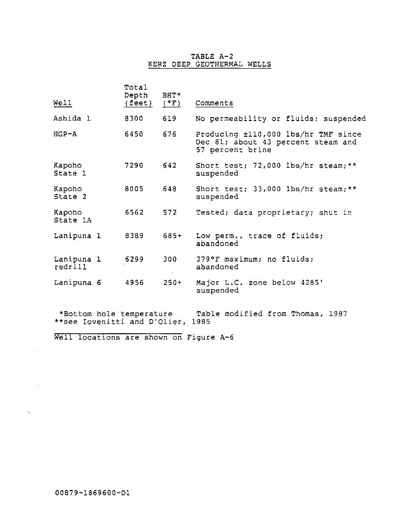
TABLE A-2 KERZ DEEP GEOTHERMAL WELLS
Well
Ashida 1
HGP-A
Kapoho State 1
Kapoho State 2
Kapoho State lA
Lanipuna
Lanipuna redrill
Lanipuna
1
1
6
Total Depth (feet)
8300
6450
7290
8005
6562
8389
6299
4956
BHT* ~
619
676
642
648
572
685+
300
250+
Comments
No permeability or fluids; suspended
Producing ±110,000 lbs/hr TMF since Dec 81; about 43 percent steam and 57 percent brine
Short test; 72,000 lbs/hr steam;** suspended
Short test; 33,000 lbs/hr steam;** suspended
Tested; data proprietary; shut in
Low perm., trace of fluids; abandoned
379°F maximum; no fluids; abandoned
Major L.C. zone below 4285' suspended
*Bottom hole temperature Table modified from Thomas, 1987 **see Iovenitti and D'Olier, 1985
Well locations are shown on Figure A-6
00879-1869600-Dl
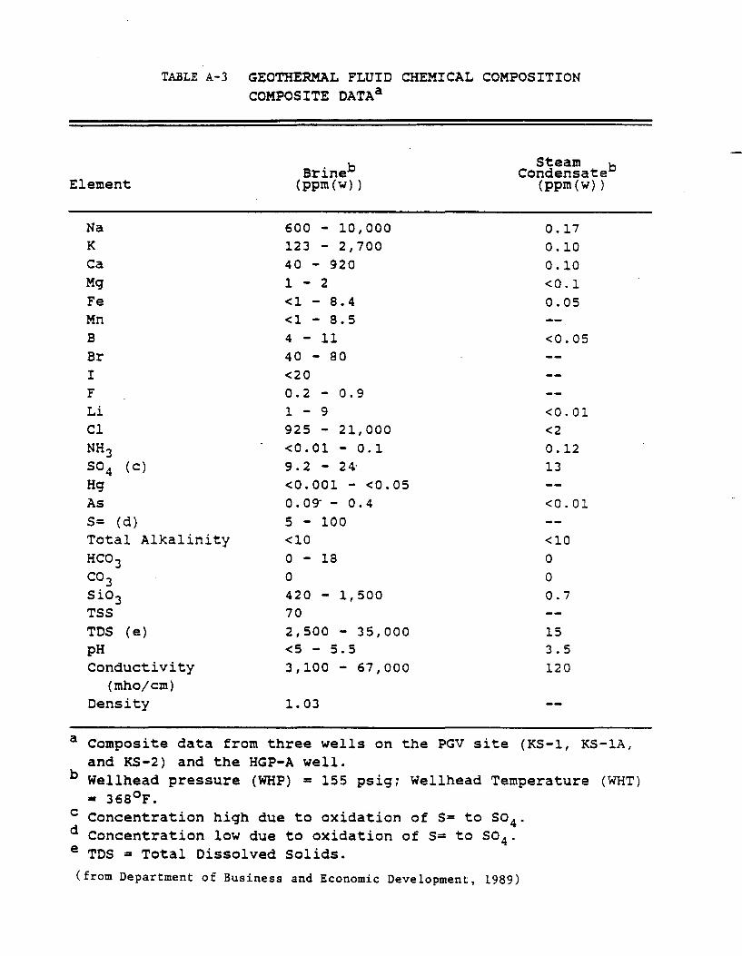
TABLE A-3 GEOTHERMAL FLUID CHEMICAL COMPOSITION COMPOSITE DATAa
Element Brineb
(ppm (w) )
Steam b Condensate
(ppm (w) )
Na K
Ca Mg Fe Mn B
Br I F
Li Cl NH 3 so4 (c)
Hg As S= (d) Total Alkalinity HC0 3 co 3 Sio3 TSS TDS (e) pH Conductivity
(mhojcm) Density
600 - 10,000 123 - 2,700 40 - 920 1 - 2 <1 - 8.4 <1 - 8.5 4 - 11 40 - 80 <20 0.2 - 0.9 1 - 9 925 - 21,000 <0.01 - 0.1 9.2 - 24; <0.001 - <0.05 o.og-- 0.4 5 - 100 <10 0 - 18 0
420 - 1,500 70 2,500 - 35,000 <5 - 5.5 3,100- 67,000
1.03
0.17 0.10 0.10 <0.1 0.05
<0.05
<0.01 <2 0.12 13
<0.01
<10 0
0
0.7
15 3.5 120
a Composite data from three wells on the PGV site (KS-1, KS-1A, and KS-2) and the HGP-A well.
b Wellhead pressure (WHP) = 155 psig; Wellhead Temperature (WHT) = 368°F.
c Concentration high due to oxidation of 5= to 504 . d Concentration low due to oxidation of 5= to 504 . e TDS = Total Dissolved Solids.
(from Department of Business and Economic Development, 1989)
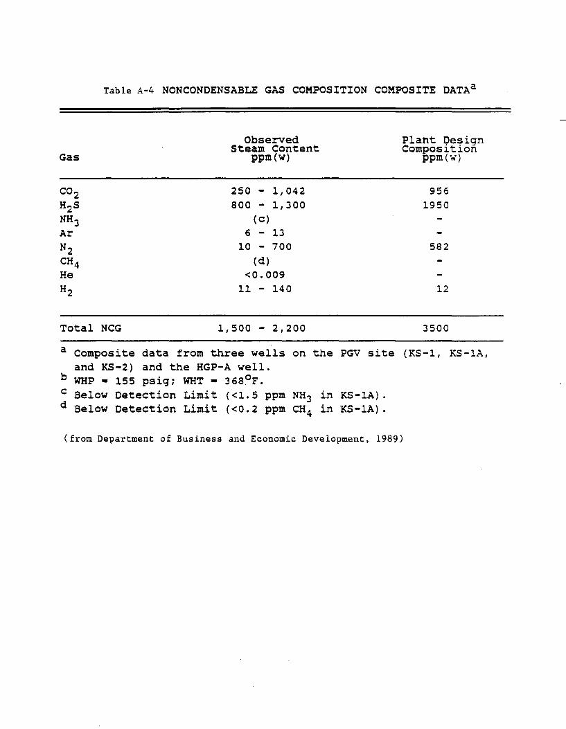
Table A-4 NONCONDENSABLE GAS COMPOSITION COMPOSITE DATAa
Gas
co2 H2S NH 3 Ar
N2 CH 4 He
H2
Total NCG
a Composite data
Observed Steam Content
ppm(w)
250 - 1,042 800 - 1,300
(c) 6 - 13
10 - 700 (d)
<0.009 11 - 140
1,500 - 2,200
from three wells on the PGV site and KS-2) and the HGP-A well.
b WHP= 155 psig; WHT = 368~F. c Below Detection Limit (<1.5 ppm NH3 in KS-lA) . d Below Detection Limit ( <0. 2 ppm CH 4 in KS-1A) .
Plant Design Composition
ppm(w)
956 1950
582
12
3500
(KS-1, KS-lA,
(from Department of Business and Economic Development, 1989)
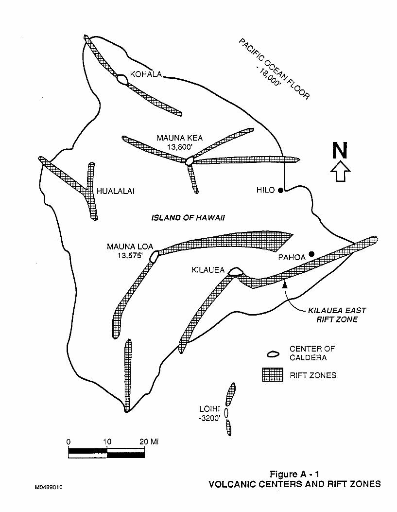
HUALALAI
0 10
M0489010
MAUNA KEA 13,800'
ISLAND OF HA WAll
20 Mi
LOIHI! -3200' ~
PAHOA e
C>
•
KILAUEA EAST RIFT ZONE
CENTER OF CALDERA
RIFT ZONES
Figure A- 1 VOLCANIC CENTERS AND RIFT ZONES
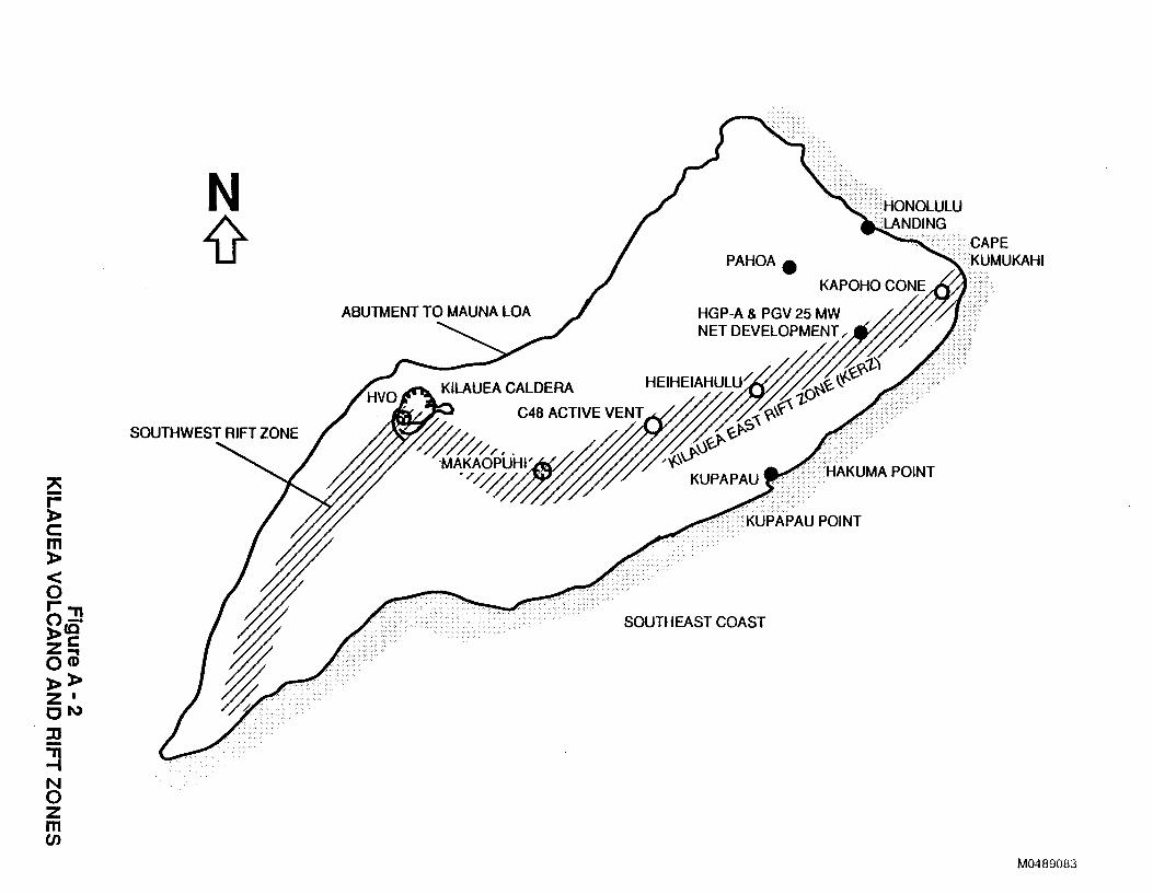
" -r-)> c m )>
< 0 r-"'11 o:J>cc zc: o<iJ )>:I> z• ON :2 ~ N 0 z m (/)
SOUTHWEST RIFT ZONE
ABUTMENT TOM AUNALOA
SOUTHEAST CO AST
····-•··••.•<HONOLULU .. LANDING
CAPE . <KUMUKAHI
M0489083
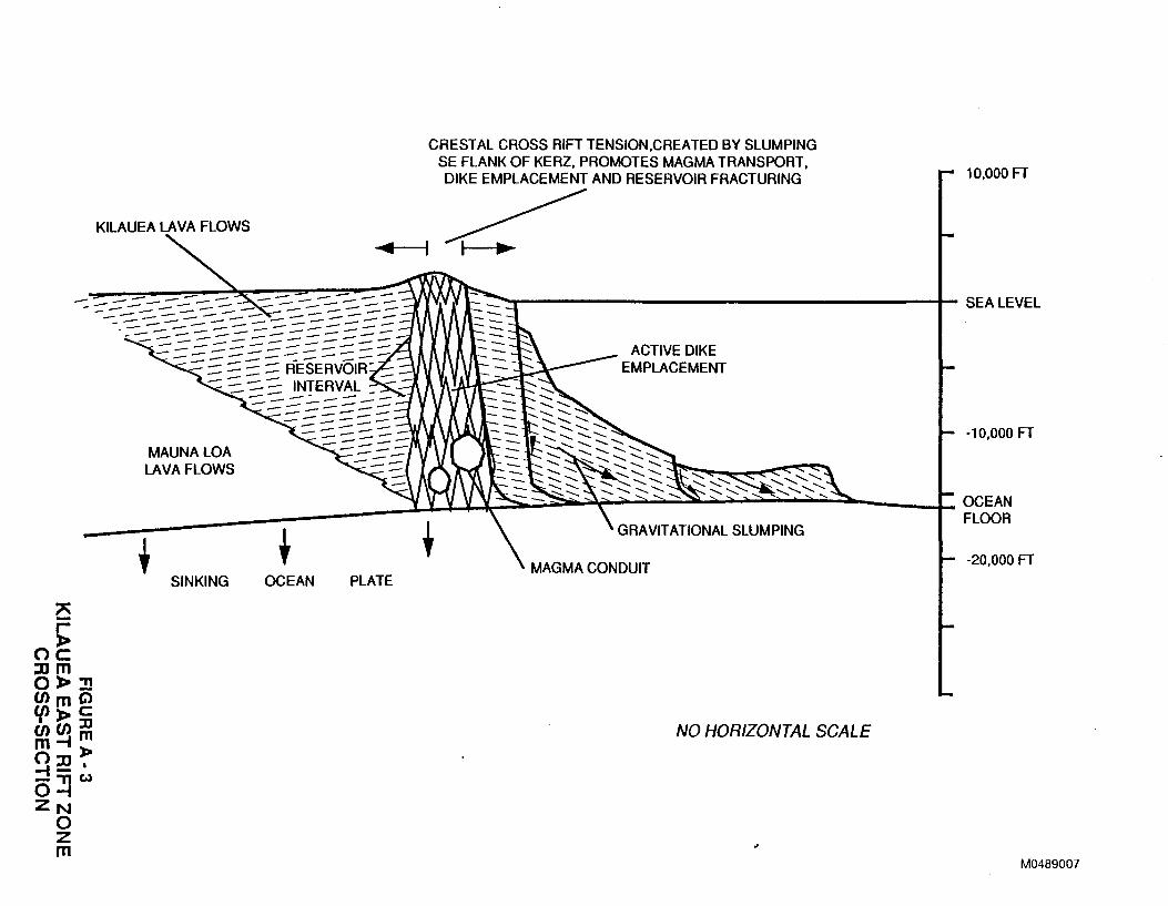
KILAUEA LAVA FLOWS
-- -----------~---=------.::::...--::::---- ---- ----- -==- ---- :::.. ::: -- ---::::..-----
MAUNALOA LAVA FLOWS
SINKING OCEAN
CRESTAL CROSS RIFT TENSION,CREATED BY SLUMPING SE FLANK OF KERZ, PROMOTES MAGMA TRANSPORT, DIKE EMPLACEMENT AND RESERVOIR FRACTURING
..... ~1---fl ~
ACTIVE DIKE EMPLACEMENT
PLATE
NO HORIZONTAL SCALE
10,000 FT
-10,000 FT
-20,000 FT
M0489007
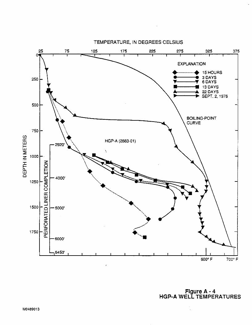
250
500
750 (./) a: UJ 1-UJ ~ z 1000
I z 0 1-
a.. 1-UJ UJ 0 ......J
a.. 4000' 1250 ~
0 (.)
a: UJ z
1500 ......J
0 5000' UJ 1-< cr: 0 u.
1750 a: UJ a..
M0489013
',
' \ \ \
\ •
TEMPERATURE, IN DEGREES CELSIUS
HGP-A (2883-01)
\
EXPLANATION
...................... ~SHOURS e----· 3DAYS ._ __ _,, 6 DAYS
-----t•• ~3 DAYS ...,.. ___ .... ., 22 DAYS
.... --~ .... ~ SEPT. 2, 1976
~ "''-....
--~
"~ ·· ....... ••• c.///
+., ,,. 600° F 700° F
Figure A- 4 HGP-A WELL TEMPERATURES
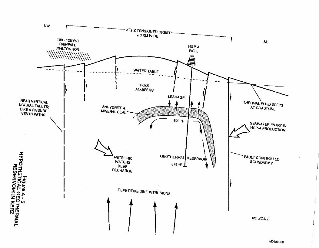
NW
r----------- KERZ TENSIONED CREST------------, :t.3KMWIDE
100 - 125./YR RAINFAll
INFilTRATION \\\\\\\\\\\\\\\\\\\ \\\\\\\\\\\\\\\\\\\
NEAR VERTICAL NORMAL FAULTS; DIKE & FISSURE VENTS PATHS
.......... ' ............... .
I I~ I
~I I I I I
, -------------------------t WATER TABLE
II COOL I , AQUIFERS
I
~METE~fliC WATERS
DEEP RECHARGE
REPETITIVE DIKE INTRUSIONS
HGP-A WELL
SE
THERMAL FlUID SEEPS AT COASTLINE
SEAWATER ENTRY IN HGP-A PRODUCTION
---FAULT CONTROLLED BOUNDARY?
NO SCALE
M04aoooa
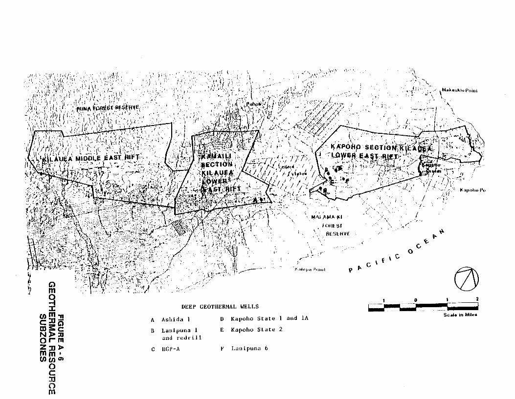
DEEP GEOTIIERHAL WELLS
A Ashida 1 D Kapoho St ate l and lA
n Lanipuna l E Kapoho State 2
and redrill
c IIGP-A F Lanipuna 6
\ ' I om ~H
fl[Sl HV£
... ·
· ... .~ I
•, I
.~. .
/ ~· l.
,• \' ··.
/'
/
/
\ Mal<euklu Poi• II \.,
''· 'I .,
")l' ... ';'.:,' .
0
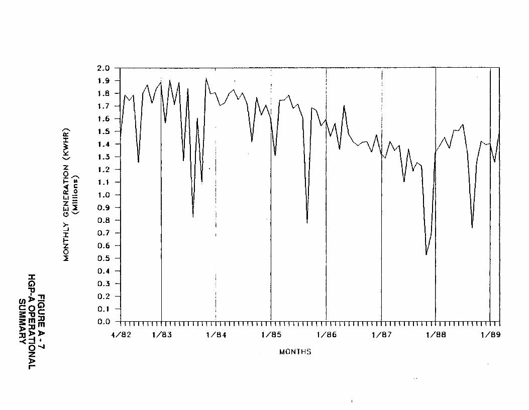
2.0
1.9
::~ ~~~ (V ~I VI ~ I V v\ AA: (\ 1.6
,........ 1.5 0:: ::t: 1.4 ~ ~ 1.3 -....,;'
z 1.2 Q,..... .... lA 1.1 <4( c 0:: 0 1.0 w= z= 0.9 w~ ~-....,;'
~ 0.8
0.7 ::t: 1-z 0.6 0 ~ 0.5
0.4 :r: G) 0.3 "U
(J)).J! 0.2 coGl 0.1 3:"UC a:mll 0.0 )>llm ll)>)> 4/82 1/83 1/84 1/85 1/86 1/87 1/88 1/89 -<::::1•
O""" MONTHS z )> r-
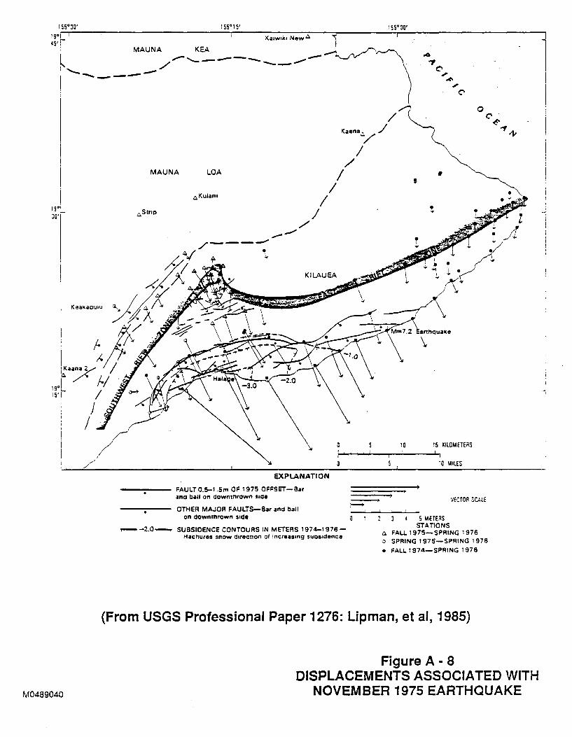
155°30' 155°15' 155° 00' 19°1 t •5r l MAUNA _... KEA '"w''' Now • l ~ / ~---- -~ -...____ _ _ _.. .0
'7 C'
I 19°1 30''-
_,.,/ ..... ,/
M0489040
MAUNA LOA
,c. Strop
t~.Kulano . I
EXPlANATION
FAULT 0.5-1.Sm OF 1975 OFFSET-Bar and bali on downthrown sode
OTHER MAJOR FAULTS-Bar and ball on downthrown Side
/
.-- -2.0.,._..,. SUSSIOENCE CONTOURS IN METERS 1974-1976-Hachures show directoon of tncreasong suosodenca
E
.; ~
.; C'
0 C'~
~-1-
10
• t
t
arthquake
\
15 KILOMETERS
10 ,\IllES
S METERS STATIONS
VECTOR SCALE
.c. FALL 1975-SPRING 1976 o SPRING 1975-SPRING 1976
• FALL 1974-SPRING 1976
...... •
(From USGS Professional Paper 1276: Lipman, et al, 1985)
Figure A- 8 DISPLACEMENTS ASSOCIATED WITH
NOVEM8ER1975EARTHQUAKE
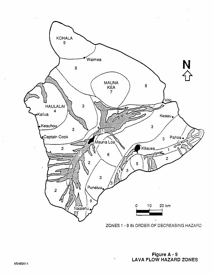
M0489011
MAUNA KEA
7
0 10 20 km
I I I
ZONES 1 - 9 IN ORDER OF DECREASING HAZARD
Figure A- 9 LAVA FLOW HAZARD ZONES
APPENDIX B
PERMIT/ENVIRONMENTAL INFORMATION for the
GEOTHERMAL/INTERISLAND TRANSMISSION PROJECT
Prepared from Public Records by
G.O. Lesperance
STATE OF HAWAII DEPARTMENT OF BUSINESS AND ECONOMIC DEVELOPMENT
April, 1989
,00858A-1869600-Dl
DISCLAIMER
Neither Hawaiian Electric Company, Stone & Webster Engineering Corporation nor any of the contributors to this document makes any warranty or representation (expressed or implied) with respect to the accuracy, completeness, or usefulness of the information contained in this document. Hawaiian Electric Company and Stone & Webster Engineering Corporation assume no responsibility for liability or damage which may result from the use of any of the information contained in this document.
00858A-1869600-Dl
"'
B.l PERMITS
APPENDIX B
PERMIT/ENVIRONMENTAL INFORMATION
FOR THE
GEOTHERMAL/INTERISLAND TRANSMISSION PROJECT
B.l.l GENERAL INFORMATION
B.l.l.l DEVELOPER Responsibility/State Assistance
To the maximum extent practicable, the State of Hawaii, Department
of Business and Economic Development (DBED) will assist the
geothermal/cable DEVELOPER with the processing of applications for
government permits and approvals. Respondents to this RFP should
be as specific as possible concerning DBED assistance required.
See Governor Waihee's letter to H.D. Williamson (attached
following the Executive Summary).
DBED will maintain a Public Document Room during the period of
this RFP. In addition, the Department of Land and Natural
Resources (DLNR) will operate a permit information and
coordination counter with a repository of laws, rules, procedures,
permit requirements and agency criteria.
PROPOSERS may telephone DBED at (808) 548-4020 or facsimile (808)
531-5243 to reserve time in the public document room. The DLNR
permit information and coordination center is located in Room 509,
Gold Bond Building, 677 Ala Moana Boulevard, Honolulu, Hawaii
96813 and can be reached at telephone number. ( 808) 548-7 443 or
facsimile number (808) 548-6233.
B-1
00858-1869600-Dl
Act 301, Session Laws of Hawaii 1988 (SLH 1988), described later
in this section, assigns the DLNR as lead agency to develop a
consolidated (federal, state and the three counties) permit and
application process for geothermal and cable development. That
process will be in place in 1990 but it will be untested as a
comprehensive and integrated process. All elements of the
permitting system as it pertains to a modestly sized geothermal
project in an Agriculture District within the Kapoho Section of
the Kilauea Lower East Rift Geothermal Resource Subzone (GRS) and
a terrestrial, one-county, AC transmission system will have been
obtained by the end of 1990 in conjunction with Ormat Energy
Systems, Inc., PGV 25 MW (net) project for sale of electricity to
the island of Hawaii utility. By the end of 1990,
True/Mid-Pacific Geothermal Venture is expected to have received
most of the necessary permits and approvals for a geothermal
project of up to 100 MW in a Conservation District within the
Kilauea Middle East GRS.
B.l.l.2 Comprehensive Permit System
Act 301, Session Laws of Hawaii 1988, the Geothermal and Cable
Sys tern Development Permitting Act of 1988, established a
consolidated permit application and review system for geothermal ~
and cable development. The DLNR is designated lead agency. All
state and county agencies are required to participate in the
system. Federal agencies are invited and have been participating.
An interagency group has been formed, and a consolidated permit
application form is being developed. Administrative Rules to
implement Act 301 are expected to be approved by the Governor,
State of Hawaii, in July 1989. A permit information and
coordination center for this Project will be in operation during
normal working hours. There is a re~ository of the laws, rules,
procedures, permit requirements and criteria of agencies which
have control or regulatory power over any aspects of this project.
B-2
00858-1869600-Dl
B.l.l.3 Public Hearings
Public hearings are required for some state and county permits. A
public hearing is a quasi-administrative (non-evidentiary) hearing
at which written and unsworn oral testimony for and against
issuing the permit is heard. Most, but not all, of the public
hearings in Hawaii are subjected to the contested case provision
which allows an aggrieved party to request a contested case
(quasi-judicial or evidentiary) hearing. Public hearings for
Conservation District Use Permits for geothermal development or
for Geothermal Resources Permits are referred to mediation rather
than contested case hearings. Appeals to decisions on these two
permits are directly to the Hawaii Supreme Court. The PROPOSERS
should account for these and other hearing requirements in
developing time frames for the permit process.
B.l.l.4 International Waters
A portion of the proposed submarine cable crossing between Hawaii
and Maui as well as between Maui and Oahu lies more than three
miles beyond either island. The State of Hawaii asserted
jurisdiction of these waters under the Archipelago waters concept.
The U.S. Government does not recognize the State's claim. The
PROPOSERS should consider the implications of this issue for
permitting the Project.
B.l.l.S Environmental Impact Statement
The DBED completed extensive environmental reviews for the cable
system (August, 1987) and for the geothermal development (March,
1989). DBED continued this process by issuing on March 10, 1989,
a Request for Proposals for the "Development of a Master Plan,
Transmission Line Routing Study, and Environmental Impact
Statement for Hawaii's Proposed Geothermal/Inter-Island Cable
Project", included here as Appendix c. The master plan and
B-3
00858-1869600-01
transmission study should be complete by March 31, 1990. The EIS
will be completed as soon as practicable after enough elements of
the master plan and transmission routing report are available to
initiate the environmental documentation process. The EIS will be
prepared around a logical but theoretical development scenario.
When applications for State permits are made, one or more EIS
supplements analyzing actual development scenarios will need to be
prepared by, and at the expense of, the Project DEVELOPER. The
PROPOSER should address the likely need for an EIS in connection
with government permits.
A U.S. Army Corps of Engineers Permit may be required for the
ocean portion{s) of the interisland transmission system. The
PROPOSER should discuss the need for a federal EIS, the expected
time frame and the prospects for state coordination with the U.S.
Army Corps of Engineers in preparing a single basis EIS document
that addresses the concerns of both federal and state law
regarding an EIS.
B.l.l.6 Geothermal Resource Subzones
Act 296, SLH 1983, the Geothermal Resource Subzone Act, amends
Hawaii's Land Use Law {Chapter 205, Hawaii Revised Statutes) to
direct the Board of Land and Natural Resources (BLNR) to make a
county by county assessment, then designate Geothermal Resource
Subzones (GRS) where there is significant geothermal potential and
where the positive economic and social benefits of geothermal
development outweigh the potentially negative environmental and
social impact. Geothermal development activity, including
exploratory drilling and power plant development, can only take
place in a designated GRS. Two subzones, the Kilauea Middle East
Rift and the Kilauea Lower East Rift including the Kamaili and
Kapoho Sections, totalling 22,000 acres have been established in
the Kilauea East Rift Zone on the island of Hawaii. One GRS was
established in the Haleakala Southwest Rift Zone on Maui. The
B-4
00858-1869600-Dl
Kapoho Section GRS abuts three small areas that were
"grandfathered" as subzones because the State had issued mining
leases before Act 296, SLH 1983, became law.
There are pending applications by a few landowners for the
assessment of their land toward designation as GRS. For purposes
of this RPP, a PROPOSER should not base the Proposal on the
premise that additional GRS will be readily designated unless that
PROPOSER has initiated action for such additional designations.
B.l.2 PERMITS FOR GEOTHERMAL RESOURCES, ENERGY GATHERING SYSTEMS, POWER PRODUCTION FACILITIES AND CONVERTER TERMINALS
B.l.2.1 Federal
There are no known federal permits required. No federal lands or
funds are involved.
B.l.2.2 State
The preponderance of permits required for this geographical regime
are state.
A Conservation District Use Permit (COUP) is required from DLNR
for geothermal development activity including exploration
development or production of electrical energy from geothermal
resources within the Conservation District. Essentially all of
the Kilauea Middle East GRS, a portion of the Kamaili Section and
a few small parts of the Kapoho Section are in the Conservation
District. The COUP requires a public hearing which, if contested,
goes to mediation. Appeals are directly to the Hawaii Supreme
Court. This permit is discussed in Chapter 205, Hawaii Revised
Statutes ( HRS) and DLNR Administrative Rules, Title 13, Chapter
184.
B-5
00858-1869600-Dl
The DLNR requires a mining lease (technically not a permit),
exploration permits, plan of operations, geothermal well drilling
permit, modification of geothermal well for injection use permit,
abandonment of geothermal well permit, and a permit to drill,
deepen, redrill, plug or alter a water well and to install,
replace or modify a pump. These permits are collectively
discussed in Chapters 177, 178 and 182, Hawaii Revised Statutes as
well as in DLNR Administrative Rules, Title 13, Chapter 166 (the
water well permit) and Chapter 183 (the first five listed
permits).
The Department of Health (DOH) requires an Underground Injection
Control (UIC) Permit (40 CFR 122 and 156; Chapter 340 E, HRS; and
DOH Administrative Rules, Title 11, Chapter 23). The Director of
Health has the option of holding a Public Hearing before issuing a
UIC Permit. DOH issues Authority to Construct and Permit to
Operate Wells and Power Plants under the Clean Air Act (Clean Air
Act; Chapter 342 HRS; and DOH Administrative Rules, Title 11,
Chapter 59 and 60). The DOH has proposed changes to Title 11,
Chapter 59, and 60 relating to geothermal air quality permits.
The Director of Health has the option of holding a Public Hearing
before issuing an Authority to Construct or Permit to Operate.
DOH is responsible for compliance with the Prevention of
Significant Deterioration requirements under the Clean Air Act. ._.
DOH also administers permits for Underground Storage Tanks.
The Department of Labor and Industrial Relations (DLIR) exercises
Occupational Safety and Health Administration (OSHA) functions
within the state. These responsibilities include permits for any
pressure vessel/boiler (Chapter 397, HRS; DLIR Administrative
Rules, Title 12, Chapter 210, 220-224).
B-6
00858-1869600-Dl
The Department of Transportation (DOT) requires a permit to
perform work upon a state highway. The DOT also requires a permit
for the movement of oversize and overweight vehicles on state
highways.
B.l.2.3 County
The County of Hawaii Planning Commission Rule 12 requires a
Geothermal Resource Permit for geothermal development activity
including exploration, development or production of electrical
energy from geothermal resources in Agriculture, Rural and Urban
Districts. This permit requires a public hearing which, if
contested, goes into mediation. Appeals go directly to the Hawaii
Supreme Court.
The counties require building,
grubbing/stockpiling permits. Some
use county streets.
electrical, plumbing, and
counties require permits to
Each county has their own permit requirements to perform work on a
county street or highway and for the movement of oversize and
overweight vehicles.
B.l.3 PERMITS FOR INTERISLAND ELECTRIC TRANSMISSION SYSTEM
B.l.3.1 Federal
Only one likely federal permit has been identified, a U.S. Army
Corps of Engineers Permit under the Clean Water Act, Section 404,
for the submarine cable portion(s) of the system. This permit may
generate the requirement for a Federal {NEPA) EIS. See Section
B.l.l for further discussion of the EIS process. When a Federal
permit is required, several federal agencies will review aspects
of the project for compliance with the federal statutes. These
may include but not be limited to the Rivers and Harbors Act of
B-7
00858-1869600-Dl
1899, Section 10, Marine Mammal Protection Act; and Endangered
Species Act, Section 7.
B.l.3.2 State
The DLNR will require a Conservation District Use Permit ( CDUP)
for any portion of the transmission system traversing a
Conservation District. A public hearing will be required which,
if contested, could generate a quasi-judicial contested case
hearing.
DLNR also manages the Natural Area Reserve System, Historic Sites
and State Parks and State Forests. Permission would be required
of DLNR to transverse these areas. These permissions could
generate public hearings and, if contested, contested case
hearings.
DLNR also manages State of Hawaii submerged lands. The ocean "'
bottom is considered submerged lands. Submerged lands are within
the Conservation District and their use will require a CDUP.
Section 171-53, HRS, requires that BLNR obtain the permission of
the Governor and the Legislature before leasing submerged lands.
The Legislature's permission would have to be obtained by a
Concurrent Resolution. The regular sessions of the Legislature
are held only from the third week of January through the third
week in April each year.
Act 301, SLH 1988, transfer red to the DLNR for purposes of the
geothermal/cable project permitting, authority for the Ocean
Waters Construction Permit which would otherwise be a DOT
responsibility. The Act also transferred to DLNR, for purposes of
the geothermal/cable project permitting, the Land Use Commission's
(LUC) responsibilities. The LUC approves amendments to land use
district boundaries, for instance, changing a particular parcel
from the Conservation to the Urban District. As a practical
B-8
00858-1869600-Dl
matter, it is unlikely that this transfer of responsibility will
matter with the geothermal/cable project. Act 296, SLH 1983,
authorized the establishment of Geothermal Resource Subzones
without regard to existing land use district boundaries.
Ordinarily, transmission lines can be installed in any land
district without the need for boundary changes.
B.l.3.3 County
The interisland transmission system will traverse three counties.
Permits will be required from each.
Each of the three counties will require a Special Management Area
(SMA) Use Fermi t and a Shoreline Setback Variance at the points
where the transmission system crosses the land-ocean inter face:
one on Hawaii; two on Maui; and one on Oahu. These two permits
are processed concurrently by each county. Further, they normally
precede any necessary state or federal land approvals. For
instance, the BLNR will probably not issue a COUP for laying the
cable on the ocean bottom until the county permits are issued.
The U.S. Army Corps of Engineers ordinarily will not issue a
permit until both state and county permits are obtained. These
two county permits will generate public hearings subject to the
contested case hearings in each of the three counties.
The City and County of Honolulu will require a Conditional Use
Permit for any structure that contains an office, storage or
maintenance facility. This permit generates two public hearings.
It normally precedes the SMA permit.
A Zoning Waiver (Height) may be required by City and County of
Honolulu as well as the County of Maui.
The City and County of Honolulu will require a Development Plan
Amendment to change to the Public Facilities Map. Amendments to
B-9
00858-1869600-Dl
the Development Plan generate two public hearings. Approval of
the Planning Commission, City Council and Mayor are required. '"''
There is a minimum 16 month processing time.
Each county will require various permits for building, electrical
and plumbing work, driveway construction and street usage (special
duty police officers for traffic control).
B.2 ENVIRONMENTAL INFORMATION
Environmental as used herein is generic, incorporating existing
physical, biological, social, and cultural conditions at the sites
which might be impacted by the proposed development. The primary
purpose of the following sections is to provide proposers with
general information developed to date by the State of Hawaii and
others which will suggest the most probable environmental issues.
Considerable data has been collected about the Kilauea East Rift
Zone/Puna District where the geothermal development, including
power production facilities, will occur. Proposers should review
the bibliography to this section. All publications listed in the
bibliography are available in the public document room.
B.2.1 TERRESTRIAL ENVIRONMENT
B.2.1.1 Soils, Geology, Seismic, Volcanic
Kilauea East Rift Zone
Kilauea on the island of Hawaii is still in a very active shield
building stage. Since January, 1983, volcanic activity has
centered on Puu 0' o in the Upper East Rift Zone. The rocks of
Kilauea are very porous and highly fractured. Evidence of local
eruptive activity, lava flows, devastated areas and steam vents
are found throughout the zone. The geologically older, low-lying
fields in the zone are covered with fertile soil and lush
B-10
00858-1869600-Dl
vegetation while the younger uplands are sparsely covered with
immature soils and dotted with Ohia trees.
Geologic hazards in the zone may include lava flows, tephra falls,
volcanic gases and pyroclastic surges, especially in the Kilauea
upland. Below grade lava tubes from past flows are a potential
problem throughout the Kilauea East Rift Zone. Indirect results
of volcanic activity are possible including earthquakes, ground
fractures and subsidence. Because the Geothermal Resource
Subzones (GRS) do not extend to near the shoreline, tsunamis are
not likely to be a concern. '
The three GRS are located in Lava Flow Hazard Zone 1, the highest
risk zone of the nine hazard zones on the island of Hawaii. The
island of Hawaii is an area classified by the Uniform Building
Code as Seismic Zone 3.
Subsidence due to withdrawal of geothermal fluids does not seem to
be a major concern.
Island of Hawaii other than the Kilauea East Rift Zone
The southern two-thirds of the Island of Hawaii is considered a
high risk area for active volcanism. The risk decreases in a
southerly direction. No volcanic activity has occured in North
Kohala for about 50,000 years.
The tsunami of April 1, 1946, caused the water to rise 14 feet
above sea level at Mahukona but did no damage. Mahukona is
considered a likely exit point for the inter island transmission
system. There is at least one report that before the first wave,
the sea had lowered as much as 35 feet. The water rose gently,
like a tide, without breakers.
B-11
00858-1869600-Dl
Maui
All of Maui is in Seismic Zone 2. East Maui consists of the
Haleakala dome which reaches 10,000 feet elevation and maintains a
cliff and valley formation from the sumrni t to the sea. The
southwest rift zone of Haleakala is inactive but "geologically
recent". The April 1, 1946, tsunami generated heights of 10 to 13
feet above sea level.
Oahu
The Waimanalo Plain on the windward side of the Koolau Mountain
Range has mostly smooth slopes of less than 10 percent. All of
Oahu is in Seismic Zone 1. The Waimanalo Plain is not a volcanic
risk area. The April 1, 1946, tsunami caused a rise of 37 feet
above normal, the highest on Oahu, on the north side of the
Makapuu Head.
8.2.1.2 Meteorology and Air Quality
Kilauea East Rift Zone (KERZ)
Westerly (night time drainage) winds occur with the greatest
frequency. Northeast daytime trade winds occur with the second
greatest frequency. Night time winds average 2.8 meters per
second (m/s) velocity and daytime 3.8 m/s. Average temperature is
22.2°C with little seasonal variation. Total annual precipitation
exceeds 2000 mm, with winter and spring having slightly more
rainfall than spring and summer. Up to a terrestrial elevation of
900 meters, annual precipitation increases significantly with
elevation. Average relative humidity is 91 percetlt. Except for
periods of heavy rains, severe weather rarely occurs.
Thunderstorms average only 8 per year, and are rarely severe.
B-12 •
00858-1869600-Dl
The u.s. Environmental Protection Agency has established atmospheric stability classes ranging from A, the most unstable, to F, the most stable. Class D indicates neutral stability
conditions. Atmospheric mixing, and hence dispersion, is greatest
during unstable conditions. In the Kapoho area, on an annual
basis, neutral atmospheric conditions (Class D) occurred
50 percent of the time, slightly unstable (Class B and C) occurred
about 25 percent of the time, extremely stable (Class E) about 20
percent, and unstable (Class A) less than 4 percent.
Average morning mixing heights at Hilo Airport range from 883 to
1555 meters and average afternoon heights from 909 to 1999 meters.
H2 5 has been continuously monitored at four sites in Kapoho since
1981/1982. The maximum 1-hour H2 S was 68 micrograms per cubic
meter.
Data on inhalable particulate matter less than 10 microns (PM 10 )
has been collected on a long-term basis in Kapoho and in the
Hawaii Volcanoes National Park. The maximum 24-hour PMt 0
concentration in Kapoho was 19.0 micrograms per cubic meter on
August 11, 1984, and in the Volcano National Park was 17.8
micrograms per cubic meter on July 23, 1984.
An extensive one-year air quality baseline survey was conducted in the KERZ in 1982/1983.
Air quality impact analysis has recently been conducted for six
different scenarios of twelve 55 MW (gross) geothermal power plants within the three GRS of the KERZ. One scenario, consisting
of four 55 MW power plants in each of the three GRS, was subjected
to air quality impact analysis to estimate pollutant
concentrations from the plants and to assess the significance of
impacts in regard to applicable ambient air quality and
increments.
B-13
00858-1869600-Dl
All modeling results seemed to indicate the PM 10 impacts would not
be a limiting factor in geothermal power plant siting unless the •
cooling tower makeup water was extremely poor in terms of total
dissolved solids concentrations. Maximum S0 2 concentrations did
not appear to be a limiting factor in the siting of power plants
in the Puna District. Each of the seven H2 S emission control
technologies (Burner/Scrubber, Stretford, LO-CAT, Claus-SCOT,
Selectox/CI, Clinsulf and Reinjection) that were modeled yielded
acceptable impacts in relation to the proposed State of Hawaii H2 S
increment of 35 micrograms per cubic meter. Under the worst case
normal operating condition emission scenario, impacts were only
slightly greater than the proposed Hawaii emission limit of 150
grams per megawatt hour.
Other than Kilauea East Rift Zone
Hazardous weather consists of strong tradewinds, kona (southwest)
winds, tropical cyclones, and hurricanes. Winds greater than 10
m/s occur on the average 92 d/yr. Cyclones pass through the
islands rarely, and then from the east. At least 20 hurricanes or
tropical storms (33.4 m/s or greater winds) approached within 480
km of the islands between 1950 and 1982. Hurricane Iwa, November
1982, with wind speeds reaching 117 mph, was considered a major
disaster for Kauai and Oahu. Undersea communications cables and
undersea pipelines were displaced during the high wave surges that
accompanied Iwa.
Since 1813, 112 tsunamis have been observed in Hawaii and 16 have
caused significant effects. The north shores of the islands are
more susceptible to inundation than other coasts.
B-14
00858-1869600-01
...
-
B.2.1.3 Hydrology/Water Quality
Kilauea East Rift Zone
Very little site specific hydrologic information is available for
the Kilauea Middle East Rift GRS and the Kamaili Section of the
Kilauea Lower East Rift GRS because economic necessity has not
prompted detailed investigations. The nearest wells are the Pahoa
wells, northeast of the Kamaili Section and the Keauohana wells
south of the Kamaili Section. Both are similar in depth (740-805
feet) and both are used for domestic supply purposes. The Pahoa
wells produce water of excellent quality and may be representative
of all areas within these subzones northwest of the rift
structure. It is thought that groundwater north of the rift zone
flows to the ocean in a northeasterly direction, generally
perpendicular to topographic contours. The Keauohana wells are
somewhat warmer and more saline. Groundwater in and south of the
rift zone in this area will be somewhat saline, depending upon the
extent of seawater intrusion as well as geothermal leakage into
the aquifer. Discharge to the ocean is direct in a southeasterly
direction.
Hydrology of the Kapoho Section of the Kilauea Lower East Rift GRS
is influenced by the transverse fault of the Kilauea East Rift at
the southwest end of the section. Groundwater downgradient of the
transverse break appears to be geothermally affected, displaying
elevated temperatures and mineral levels. Groundwaters flow
southwest. Permeabilities are high except for an ash layer near
Kapoho Crater. Although there are no recorded wells north of the
Kapoho Section, the high quality of the Pahoa wells suggests that
groundwater quality may improve in a northerly direction.
Data from the HGP-A well suggest very limited interaction between
the geothermal reservoir and the shallower groundwater aquifers.
Changes in the chemical composition of HGP-A fluids suggest that
B-15
00858-1869600-Dl
either the seawater component of the reservoir has been increasing
as fluids have been discharged from it or that the flash front is
migrating out into the formation.
Surface and groundwater are not likely to be impacted during
normal, uneventful drilling operations. However, groundwater in
the vicinity of each new geothermal well should be tested during
the drilling.
Based on the HGP-A well chemistry the brines would not be toxic to
groundwater. However, geothermal fluids at other locations may
have different chemistries.
Other than Kilauea East Rift Zone
The landforms of surface water drainage basins reflect the
geologic age and rainfall in different parts of the Hawaiian
Islands, and watersheds are typically small. For Maui, flooding
of Pahihi Gulch at Huakini may occur during periods of heavy
rainfall. For Oahu, most of the coastline is within the 100-year
flooding zone. The inland areas on Oahu, where the transmission
system preferred route would traverse, are not subject to
flooding.
B.2.1.4 Noise
Kilauea East Rift Zone
Noise measurement data in the KERZ are very limited. An
environmental noise survey was conducted as part of the Puna
Geothermal Venture (PGV) Project Environmental Impact Statement at
two residential locations near the PGV site in Pohoiki.
Background noise levels during the survey ranged from 34.2 dBA
(7 p.m.) to 53.2 dBA (5 a.m.), which exceeds the county night time
noise guidelines of 45 dBA. The high background noise level was
B-16
00858-1869600-Dl
1111!
•·
due to moderate winds and precipitation in the area during the
noise survey.
The Occupation Safety and Health Administration (OSHA)
requirements for the workplace specify that no worker should be
exposed to 115 dBA for more than 15 minutes, or to 90 dBA for more
than eight hours. The U.S. EPA (1978) recommends that noise
limitations should conform, as an initial minimum, to the
regulations issued by the U.S. Geological Survey for geothermal
operations on federal lands; i.e., not to exceed 65 dBA at the
lease boundary or one-half mile from the source, whichever is
greater.
The County of Hawaii Planning Department noise guidelines specify
55 dBA during the daytime (0700 to 1900) and 45 dBA during the
night time (1900 to 0700) as satisfactory for residential areas.
Short duration (less than one second) impact noise limits are 10
dBA higher than either the daytime or night time limits but may
not be exceeded more than 10 percent of the time in any 20-minute
period.
Other than Kilauea East Rift Zone
The proposed overland corridors of the interisland transmission
system encompass land used for agriculture, grazing, pasture land
and rural residential areas. The background noise levels in these
areas would normally be below 45 dBA.
During construction/deployment of the transmission system, the
loudest example evaluated, a hovering helicopter, would generate
up to 93 dBA at 100 feet. Increases in noise levels would occur
on a short-term basis. Mitigation of this impact would be done
through restriction of operating hours, and would probably be a
condition attached to one or more necessary permits.
B-17
00858-1869600-Dl
B.2.1.5 Fauna/Flora
Kilauea East Rift Zone
Twenty-one bird species have been recorded from the Geothermal
Resources Subzones. Of the six endemic species, the Hawaiian Hawk
or 1 I 1 o is the only listed endangered species. The endangered 1 0 1 u, considered the rarest of the surviving honeycreepers on the
island of Hawaii, has been observed in the upper elevations of the
Puna Forest Reserve in which the Kilauea Middle East GRS is
located. In general, the other endemic species (Hawiian Thrush, 1 0ma 1 o, 1 Elepaio, 1 Amaki hi, 1 I 1 iwi, and 1 Apapane) are found in
this GRS.
Except for the native Hawaiian Hoary Bat or 1 0pe 1 ope 1 a, an
endangered species, all the other mammals found within the GRS
were introduced by human beings either accidentally or
intentionally. The bat probably occurs throughout the GRS,
preferentially foraging in forest openings, along forest edges, or
over bodies of water. The nocturnal habits of this species makes
detection and observation difficult.
Inventories of invertebrate resources have not been included in
biological studies. A fairly rich complement of native
invertebrates, including relatively diverse
ties, can be expected in the less disturbed
Lava tubes may support cave invertebrates,
candidates for endangered status.
arthropod communi
vegetation types.
some of which are
Intact forests dominated by native flora species are of special
concerns. Such forests are more likely to provide refuge for
threatened and endangered plants and animals. Siting of access
roads, well pads, power plants and other facilities on barren lava
flows, areas of stand-level dieback and areas dominated by
introduced plants, is preferred. Permits for development within
B-18
00858-1869600-Dl
forests are likely to require site-specific biologic surveys
before clearing is undertaken.
Other than Kilauea East Rift Zone
The predominantly introduced vegetation of the low elevation areas
of the Island of Hawaii corridor does not provide suitable habitat
for endemic Hawaiian forest birds. The Hawaiian hawk (endangered,
endemic), Hawaiian owl (endemic) and the Hawaiian hoary bat
(endangered) are known to occur in the Hilo area.
The green sea turtle and hawksbill sea turtle, both endangered
species are likely to come ashore briefly and for short distances,
on all islands.
Streams are generally considered special habitats for native
aquatic animals. The only perennial stream in the proposed
transmission corridors is the Waiulaula Stream in the Kawaihae
area in northwest Hawaii.
The Ahihi-Kinau Natural Area Reserve on Maui is the only wetlands
within the general area of the proposed transmission corridors.
This protected area has a system of brackish anchialine ponds.
Kipuka' s, older forests surrounded by more recent lava, are of
interest. They occur in the saddle between Mauna Kea and Mauna
Loa.
8.2.1.6 Archaeological/Cultural
Kilauea East Rift Zone
Puna was one of the six ancient districts or moku of the Island of
Hawaii. Traditional accounts relate that Puna was a rich
B-19
00858-1869600-Dl
agricultural region, a center of development of religion, and
focus for myths concerning the goddess Pele.
The Kilauea Middle East Rift GRS probably does not contain any
significant archaeological sites other than temporary shelters,
trails and forest planting areas. There are some possible cairns
at Heiheiahulu. Within the Kamaili Section there are no recorded
archaeological sites. The Kapoho Section contains the largest
number of sites or potential site areas. Most of these are at or
near cinder cones. Kuukii Cinder Pit is where a heiau and spring
have been recorded. Holua slides have been identified. Other
identified archaeological sites have been inundated by the 1955
and 1960 lava flows.
In a 1982 survey, the Puna Hui Ohana identified 413 adult
Hawaiians residing in lower Puna, predominantly in Hawaiian
Beaches (42.5 percent), Pahoa (21.9 percent), or Kalapana
(.18.8 percent). The survey included 85 percent of the area
population. Forty-two percent of the Hawaiians viewed the overall
impact of geothermal development as bad (Hawaiian culture;
historical sites; traditional religion; and hunting, fishing and
gathering; plus the more typical concerns such as traffic,
agricultural land, land taxes, physical environment, quakes,
eruptive, plants and animals). Positive responses were generally
around the theme that geothermal development is good for the •
economy.
A group of Pele practitioners opposed geothermal development on
the grounds that it threatens Pele and Hawaiians' relationship to
the goddess, Hawaiian relationships with the land and Hawaiian
identity. When the Pele practitioners asked the Hawaii Supreme
Court to stop geothermal development on religious grounds, the
Court in July 1987 unanimously found that the plaintiffs did not
show that development would do significant harm to the exercise of
B-20
00858-1869600-Dl
their religion. The U.S. Supreme Court, in April 1988, decided
not to review the Hawaii decision.
Other than Kilauea East Rift Zone
The Historic Sites Section of the Department of Land and Natural
Resources Parks Division lists historic and archaeological sites
on both State and National Registers of Historic Places. There
are eleven specific sites in the general vicinity of the proposed
transmission route on Maui and nine on Oahu. There are numerous
archaeological and historic sites on the island of Hawaii and
there are believed to be many undiscovered sites island wide.
8.2.1.7 Land Use and Zoning
Kilauea East Rift Zone
The KERZ lies entirely within the 500 square mile Puna District.
About 74 percent of Puna's land is unused open space of which less
than 29,000 acres in Puna is actually being used for agriculture.
Puna has 51,000 vacant parcels, ranging in size from 4,000 square
feet to 10,000 acres, with most larger than one acre. In the 1980
census, there were 5,529 year-round housing units.
In the Kapoho Section of the lower East Rift GRS, approximately 85
percent of the total 7, 350 acres is unused open space.
Residential use, all on agriculture-zoned land, accounts for less
than one percent of the total area.
The Kamaili Section of the lower East Rift GRS is all zoned ' agriculture.
open space.
Most of the 5,530 acre subzone is presently unused
B-21
00858-1869600-:-Dl
The 9,104 acre Kilauea Middle East Rift GRS is classified Forest
Reserve. Over 600 acres in the southeast corner are in the
agricultural district.
In Puna, about 148 acres are for commercial uses, including land
for services.
A large number of large-lot subdivisions were created during the
1950s and 1960s. They were constructed on relatively recent lava
flows and most, even today, lack county-standard roads, water and
sewer lines. Some portions are not served by electricity or
telephone lineS'.
Other than Kilauea East Rift Zone
With the exception of Hilo, the entire proposed cross-island •
transmission corridors on the island of Hawaii are rural in
character, have a low population density, and are far from
residential communities. There is rapid resort development in the
Kohala coastal region. There are no major commercial or
industrial activities along the route. There is a small
residential area near the Kaumana substation. Kawaihae Harbor is
a commercial deep draft port. Mahukona harbor is a dilapidated
small boat harbor.
The proposed transmission corridor on Maui is presently very rural
in character. The entire study area is within the 1980 census
tract number 303.02 which has a land area of 45,442 acres, a
resident population of 1,227 people and 474 households. This
census tract includes the Kihei-Makena resort
experienced major population growth in the past
area which has
fifteen years.
The proposed route on Oahu is also rural in character. Waimanalo
is the closest urban center within 1980 census tract number 113 •
B-22
oo85e-la696oo-o1
which has a land area of 7,100 acres, 1980 resident population of
9,132 people and 2,137 households.
8.2.1.8 Aesthetics/Visual Impact
Generally, the views from existing highways and roads are
panoramic, predominantly rural and undeveloped, with the ocean
often visible. Although few specific viewsheds are protected by
land use laws, preservation of visual quality is a statewide goal.
No formal ordinances exist concerning visual resources for the
study areas. However, sightseeing is a popular activity for
tourists, which represent Hawaii's largest industry.
8.2.1.9 Social/Economic
Kilauea East Rift Zone
Puna's economy is distinctive for the Island of Hawaii in that it
lacks major tourism investment and no longer produces sugar.
Diversified agriculture, including papayas, macadamia nuts,
bananas, flowers and foliage, has taken an increased importance.
Puna residents often stress that they like the relatively
undeveloped character of the district but they are concerned about
the availability of jobs and limited infrastructure. Residents
describe themselves as rural or as having a rural life-style.
A 1986 survey showed 66 percent of the residents favoring and 18
percent opposed to small-scale geothermal development to serve the
island of Hawaii, but were nearly evenly divided concerning
large-scale geothermal development including export to Oahu.
There is significant concern about decrease in residential land
values with large-scale geothermal development.
8-23
00858-1869600-Dl
Other than Kilauea East Rift Zone
Much of the Kohala District on the island of Hawaii is being
developed into expensive resorts and ranches. This area is
predominantly flatland-ridge/grassland landscape where trans
mission structures would often be in silhouette against the sky or
a distant background form lacking visible texture.
B.2.2 MARINE
B.2.2.1 Bathymetry
About 80 percent (178 kilometers) of the suggested submarine route
is in less than 547 meter depths, 12 percent (27 kilometers) are
between 547 and 1,094 meters and (all within the Alenuihaha
Channel) 3.6 percent (nine kilometers) are between 1,094 and 1,641
meters and another eight kilometers between 1,641 and 2,188
meters. The proposed route was selected to avoid steep slopes.
Where steep slopes could not be avoided, a route perpendicular to
bottom contours was selected. The route also avoids areas of
excessive bottom roughness to minimize unsupported spans and
abrupt bending radii. Proposers are strongly urged to verify
preferred route bathymetry by studying the bathymetric survey data
available in the public document room.
B.2.2.2 Marine Biology
Within the general area of the proposed cable system occur the
endangered Hawaiian monk seal, the endangered humpback whale, the
threatened sea turtle, and occasionally, the endangered hawksbill,
the threatened loggerhead, the endangered leatherback and the
threatened Pacific ridley sea turtles. The Marine Mammal
Protection Act of 1972 prohibits acts which unintentionally affect
the natural behavior of marine mammals including non-threatened
whales and dolphins that occur in Hawaiian waters.
B-24
00858-1869600-Dl
••
Major beds of precious corals (pink, gold, bamboo and black
corals) occur offshore at Mahukona (Island of Hawaii), Ahihi Bay
(Island of Maui), in the Auau Channel between Lanai and Maui, and
off Makapuu (Oahu).
Proposals should include a plan for analyzing impacts and
addressing issues arising under the Endangered Species Act and
other statutes.
B.2.2.3 Physical Oceanography
The summer wave climate is dominated by the strong northeasterly
tradewind-generated waves as well as southern swell generated by
distant winter storms in the southern hemisphere. The tradewind
waves predominate in the Alenuihaha Channel. However, both wave
types can occur simultaneously. The winter wave climate is
characterized by a weakening of the tradewinds and the occurrence
of infrequent southerly "Kona" storm waves as well as frequent
northwesterly swells from North Pacific winter storms or
mid-latitude low pressure systems. Alenuihaha is somewhat
sheltered from the northwesterly swell but is directly exposed to
southwesterly waves.
Below 300-400 meters predictable tidal current magnitudes and
phases occur, although site-specific studies are recommended. In
the open ocean, peak tidal currents are towards the SSW under the
wave crest (high tide) and towards the NNE under the wave trough
(low tide). Around the islands, however, the tidal waves interact
with the island masses, creating mixed currents and eddies as well
as flow intensification through channels.
Tides in Hawaii are predominantly semi-diurnal with diurnal
inequality. Typical tidal cur rents are less than a half knot.
Peak currents may reach one knot.
B-25
00858-1869600-Dl
8.2.2.4 Navigation/Ocean Uses
The proposed submarine route is outside of major U.S. and foreign
shipping lanes except in the Molokai Channel. There are
inter island tug and barge services, luxury liners and numerous
smaller private vessels.
The U.S. Navy is a significant user of the seabed, surface and
subsurface waters around the Hawaiian islands, and has established
two area classifications for use: Warning Areas and Fleet
Operating Areas. The only restricted area near the proposed cable
system is the ocean area of three miles surrounding the Island of
Kahoolawe. The proposed cable route avoids this area.
The military maintains communications and other cables in offshore
Hawaiian waters. Once a final route is selected for the •
interisland tranmission cable system, the Navy should be contacted
to provide information regarding potential conflicts. Similarly,
Hawaiian Telephone Company and other private communication
companies should be contacted once a final route is selected to
avoid potential conflicts.
The most valuable commercial fishery in Hawaii is tuna longlining
with the second largest being live-bait, pole-and-line for
skipjack tuna. In 1981-1982, roughly 200 vessels {predominantly
commercial charter-fishing) indicated they trolled commercially in
Hawaiian waters and 1,000 additional boats and fishermen indicated
that they combine trolling with other types of commercial fishing.
An estimated 250 small boats are in the tuna handline fishery.
There is a network of Fish Aggregating Devices {FADs) anchored
buoys, around the islands; however, the preferred route avoids
existing FADs by three miles.
B-26
00858-1869600-Dl
B.3 BIBLIOGRAPHY FOR APPENDIX B
Anderson, Bruce S. and N. M. Oyama. 1987. A Study of the Health
Status of Residents in Puna, Hawaii Exposed to Low Levels of
Hydrogen Sulfide. Hawaii State Department of Health, Research and
Statistics Office, RNS Report No. 56.
Char, W.P. and C.H. Lamoureux. 1985. Puna Geothermal Area Biotic
Assessment, Puna District, County of Hawaii. Prepared for Hawaii
State Department of Planning and Economic Development. 127 pp. +
maps and figures.
Charry, J .M. 1986. "Assessing and Managing Potential Health and
Safety Issues Related to High Voltage Direct Current Transmission
Lines."· Environmental Research Information, Inc. Prepared for
Parsons Hawaii, Hawaiian Electric Company, Inc. and the Hawaii
Department of Planning and Economic Development.
Dames & Moore. 1984. Evaluation of BACT for and Air Quality
Impact of Potential Geothermal Development in Hawaii. EPA
Contract 68-02-3508.
Dames & Moore. 1989. Puna Geothermal Zone Development Cumulative
Air Quality Analysis. Prepared for the Department of Business and
Economic Development. Dames & Moore Job No. 16274-003-001.
Department of Land and Natural Resources ( DLNR) . 1984.
Environmental Impact Analysis of Potential Geothermal Resource
Areas. Circular C-106. Division of Water and Land Development.
of Planning and Economic Department
Geothermal
Hawaii.
Resource Subzone Designations
B-27
00858-1869600-Dl
Development. 1986.
in Hawaii. Honolulu,
DHM Planners, Inc. 1985. Hawaii Deep Water Cable Program, Phase
II-B: Overland Transmission Corridor Study: Hawaii, Maui, Oahu.
Report prepared for Parsons Hawaii, Hawaiian Electric Company,
Inc. and the Hawaii Department of Planning and Economic
Development.
DHM Planners, Inc. 1985. Hawaii Deep Water Cable Program, Phase
II-C: Visual Impact Analysis of Proposed 300 KVDC Line. Prepared
for Parsons Hawaii, Hawaiian Electric Company, Inc. and the Hawaii
Department of Planning and Economic Development.
DHM Planners, Inc. 1987. Hawaii Deep Water Cable Program, Over
land Transmission Line Corridor Study: Puna to Kohala Island of
Hawaii. Prepared for Parsons Hawaii, Hawaiian Electric Company,
Inc. and the Hawaii Department of Business and Economic
Development.
Dinell, T. and J. Goody. 1988. Settling Differences: Alternate
Energy Developments and Citizen Opposition.
Resolution, University of Hawaii at Manoa,
1988-1.
Program on Conflict
Working Paper No.
Edaw, Inc. 1983. Draft Environmental Impact Statement, Kaumana
to Keamuku 138 KV Transmission Line. Prepared for Hawaii Electric
Light Co.
Edward K. Noda and Associates. 1986. Hawaii Deep Water Cable
Program. Phase II-C: Environmental Design Criteria for Cable
Deployment Operations in the Alenuihaha Channel. prepared for
Hawaiian Dredging and Construction Co., Parsons Hawaii, Hawaiian
Electric Company, Inc., and the Department of Planning and Econom
ic Development.
B-28
00858-1869600-Dl
:Iii'!>-
.,
Fluor Technology, Inc. 1987. Environmental Impact Statement:
Puna Geothermal Venture Project.
Company.
Prepared for Thermal Power
Makai Ocean Engineering, Inc., Ed Noda & Associates and Hawaii
Institute of Geophysics. 1986. Hawaii Deep Water Cable Program,
Phase II: Bottom Roughness Survey of the Alenuihaha Channel.
Prepared for Hawaiian Dredging and Construction Co., Parsons
Hawaii, Hawaiian Electric Company, Inc., and the U.S. Department
of Energy.
Makai Ocean Engineering, Inc. and Scripps Institute of Oceano
graphy. 1987. Hawaii Deep Water Cable Program, Phase II-C:
Second Bottom Roughness Survey of the Alenuihaha Channel. Pre
pared for Hawaiian Dredging and Construction Co., Parsons Hawaii,
Hawaiian Electric Company, Inc., and the Hawaii Department of
Planning and Economic Development.
MCM Planning. 1989. Environmental Review, SOOMW Geothermal
Development Within the Puna District, Island of Hawaii. Prepared
for the Hawaii Department of Business and Economic Development.
NEA, Inc. 1984. Environmental Baseline Survey, Kilauea East Rift
(year two). Puna and Ka'u Districts, County of Hawaii. January
1, 1984 through December 31, 1984 Study Period. Volume I and II.
Par sons Hawaii. 1987. Hawaii Deep Water Cable Program, Phase
II-C Environmental Constraints to Use of a Sea Electrode in a
Submarine Electrical Transmission Cable System in Hawaii. Report
prepared for Hawaiian Electric Company, Inc. and Hawaii Department
of Planning and Economic Development.
Par sons Hawaii. 1987. Hawaii Deep Water Cable Program. Phase
II-C. Task 1. Environmental Assessment.
B-29
00858-1869600-Dl
Puna Hu i Ohana . 1982. Assessment of Geothermal Development
Impact on Aboriginal Hawaiians.
Energy. Pahoa, Hawaii.
Prepared for U.S. Department of
SMS Research,. Inc. 1982. The Puna Community Survey. Prepared
for the Hawaii Department of Planning and Economic Development and
County of Hawaii Department of Planning. 2 vols.
SMS Research, Inc. 1986. Geothermal Energy Development Opinion
in the County of Hawaii. Prepared for the Energy Division, Hawaii
State Department of Planning and Economic Development.
SMS Research, Inc. 1987. Consumer Opinions about Geothermal
Energy. Prepared for the Energy Division, Hawaii State Department
of Planning and Economic Development.
Sumida, G.A. and A.L. Hills. 1984. Legal, Institutional and
''"
Financial Aspects of an Inter-Island Electrical Transmission •
Cable. Prepared for the Hawaii Department of Planning- and Econo-
mic Development.
Sumida, G.A., A.L. Hills, P.E. Lee, S.D. Suyat and R.P. Takushi.
1986. Al terna ti ve Approaches to the Legal, Institutional and
Final Aspects of an Inter-Island Electrical Transmission Cable
System. Prepared for the Hawaii Department of Planning and
Economic Development.
Towill, R.M. Corporation. 1982a. Revised Environmental Impact
State for the Kahauale' a Geothermal Project, District of Puna,
Island of Hawaii. State of Hawaii. Prepared for True/Mid-Pacific
Geothermal Venture.
Towill, R.M. Corporation. 1986. Final Supplemental Environmental
Impact Statement to the Revised Environmental Impact Statement for
B-30
00858-1869600-D1

the Kahauale'a Geothermal Project. Prepared for True/Mid-Pacific
Geothermal Venture.
B-31
00858-1869600-Dl
March 10, 1989
REQUEST FOR PROPOSALS
DEVELOPMENT OF A MASTER PLAN, TRANSMISSION LINE ROUTING
STUDY, AND ENVIRONMENTAL IMPACT STATEMENT FOR
HAWAII'S PROPOSED GEOTHERMAL/INTER-ISLAND CABLE PROJECT
This letter is to invite your proposal to prepare a Master Development Plan, conduct a public involvement program, conduct an evaluation of overland transmission corridors and prepare a routing report, conduct a public involvement program, and prepare an Environmental Impact Statement for the development of 500 megawatts (net) of geothermal resource in the Kilauea East Rift Zone on the Island of Hawaii and transmit it to Maui and Oahu via an inter-island electrical transmission system. The Master Development Plan is desired by the end of 1989. It is expected that the location and selection of overland transmission line corridors will take place in 1989, with the preparation of routing report to be completed in 1990. It is expected that this routing study be conducted with the full benefit of a public involvement program. With the completion of the master plan and routing work, the State desires an Environmental Impact StatemeRt which will lead to the permitting of the project. Permitting assistance will be requested as a separate additive proposal item under this solicitation.
Proposals are due no later than April 13, 1989.
The attached Notice of Intent to Respond is due no later than March 29, 1989.
Attached, for your information and use, is a brief description of the purpose and intended scope of this project. Any questions concerning this Request for Proposals shall be addressed to:
Director, Department of Business and Economic Development Attn: Maurice H. Kaya, Energy Program Administrator
335 Merchant Street, Room 110 Honolulu, Hawaii 96813
Tel: (808) 548-4150
us1ness an Development
March 10, 1989
REQUEST FOR PROPOSALS
DEVELOPMENT OF A MASTER PLAN, TRANSMISSION LINE
ROUTING STUDY, AND ENVIRONMENTAL IMPACT STATEMENT
FOR HAWAII'S PROPOSED GEOTHERMAL/INTER-ISLAND
CABLE PROJECT
The State of Hawaii •s Department of Business and Economic Development (DBED) invites proposals to prepare a Master Development Plan, conduct a public involvement program; evaluate overland transm~ssion line corridors, prepare a routing report, and prepare an Environmental Impact Statement for the development of 500 megawatts (net) of geothermal resource on the Island of Hawaii and transmit it to Oahu and Maui via an inter-island cable system, hereinafter called the geothermal/cable project. Included as an additive proposal item is the preparation and submission of Federal, State and County permit applications. Seven copies of the proposal are due on, or before 4:00 p.m., HST, on April 13, 1989. The proposals shall be mailed or delivered to:
Director, Department of Business and Economic Development 335 Merchant Street, Room 110
Honolulu, Hawaii 96813
Attn: Maurice H. Kaya Energy Program Administrator
-1-
I. INTRODUCTION
A. PURPOSE
The purpose of this Request for Proposals is to select a consultant to perform planning and engineering functions relating to the geothermal/cable project to guide public and private decision-making relative to the implementation of the project. During 1989 and 1990, the State of Hawaii and the Hawaiian Electric Company, Inc. (HECO) will be requesting, receiving and evaluating proposals for the private sector to finance and implement the geothermal/cable project. The Master Development Plan to be developed as a result of this RFP will assist that process.
The development of this plan must consider the multitude of reports and studies that have already been conducted to date regarding geothermal and deep water cable development in Hawaii. This project has not been without controversy, and the preliminary work that has been done has revealed concern particularly by those communities in the lower Puna district of the Big Island, over the impact of this widespread development on their neighborhoods. It is therefore expected that the public in potentially affected areas of all counties would want to have input in the planning for this project.
Despite the controversies, the State recognizes the importance of developing its ·geothermal resource to its fullest potential to achieve a significant degree of energy independence. Private development of the resource has been slow, and the State believes that it is necessary to conduct this planning to show leadership and commitment, to invest in the upfront engineering activities so that an eventual private development consortium will assume responsibility for financing and development and sale of electricity to HECO.
B. BACKGROUND
Hawaii's deep concern for its energy future is a result of the State's extremely high reliance upon petroleum in an unstable world market. Despite the current world oversupply and the recent decline in price, there is widespread opinion that the current worldwide surplus oil production capacity will likely be exhausted in less than a decade. Thereafter an escalation in oil price is expected. Energy experts differ greatly as to exactly when and how rapidly prices will rise. This uncertainty emphasizes the need for Hawaii to take active measures to reduce its oil dependence and improve its energy stabtlity and security. This need becomes imperative in the light of the serious negative impact of high energy costs on our State economy.
-2-
Petroleum accounts for ninety percent of Hawaii's total energy supply, twice the national average. In the case of electrical power generation, the contrast between Hawaii and the rest of the nation is even greater. While the nation's utilities have reduced their use of oil to a point where petroleum products now account for only about five percent of the fuel consumed for power generation, Hawaii •s utilities have continued to rely almost entirely on oil. Nationally, coal is the leading source of energy for power generation, accounting for fifty-six percent of the fuel used. Locally, coal will be used for the generation of power on Oahu for the first time starting in 1992.
Recognizing Hawaii's energy vulnerability, the Hawaii State Plan, adopted by the State Legislature in 1978, sets forth the following energy objectives: Dependable, efficient, and economical statewide energy--systems capable of supporting the needs of the people; and increased energy self-sufficiency.
To meet the objectives stated above requires serious consideration of the use of locally available energy resources. There are several candidates in various stages of technical maturity. However, geothermal energy is the only near-term indigenous source which can bring about significant energy self-sufficiency in Hawaii.
Geothermal energy has proven to be technically and economically feasible elsewhere. Scientists estimate that there is sufficient thermal energy on the Big Island to satisfy at least half of the State's total electricity requirements. Because geothermal resources are located primarily on the Big Island, and Oahu represents eighty percent of the demand, successful utilization of geothermal energy requires transmission of electric power between the Islands. The most feasible method of transporting electricity under the conditions involved is by high-voltage, direct-current (HVDC) submarine cables. Such a transmission method has been under study for several years.
The Hawaii Deep Water Cable (HDWC) Program, a $27 million project funded by the Federal Government and the State, was started in 1980. Its purpose is to develop the technology of a cable system to transmit electricity between the islands of Hawaii. This requires a transmission cable capable of traversing a distance of 150 miles in ocean depths down to 6,300 feet. This is twice the distance and four times the depth of the longest and deepest cable laid to date anywhere in the world. The HDWC has produced a design for an electric transmission cable which is expected to satisfy Hawaii's requirements. A segment of a cable meeting design requirements has undergone electrical and mechanical testing in the laboratory. This testing demonstrated that the cable can withstand a thirty-year operating life under the design parameters identified for the Hawaii application. These laboratory tests are being followed by testing to confirm the validity of the subsystem integration plans in 1989 at sea with a six mile length of surrogate cable. The technical feasibility of a cable system for commercial application will be confirmed with the completion of these at-sea tests. Ocean bottom surveys have identified a feasible cable route linking Hawaii with Maui and Oahu.
-3-
The Hawaiian Electric Company, providing Oahu with electricity, will be the buyer of power produced and transmitted by the geothermal/cable project. It has confirmed that the utility system on Oahu is capable of accepting 500 megawatts of 11 COmpetitively priced 11 baseload geothermal power phased in between 1995 and 2006. This is the basis upon which cable and geothermal development planning is proceeding. The cable system is estimated to cost about $450 million, with the geothermal development for 500 MW estimated to cost approximately $1.3 billion in 1986.
Private investments made to date for geothermal development in Hawaii exceed $20 million, although no commercial plant has yet been constructed. Presently there are two firms actively involved in geothermal development activities on the Island of Hawaii--Ormat Energy Systems, Inc., and True/Mid-Pacific Geothermal Venture. Ormat has entered into a contract with the Hawaii Electric Light Company on the Island of Hawaii to provide 25 MW of geothermal power by 1991 to meet the Island's needs. True/Mid-Pacific Geothermal Venture has been trying for years to get the necessary permits to start exploration for geothermal resources. Although one of the objecting parties are still in the courts, it is anticipated that its permits will soon be confirmed and it can at long last begin its work. It will have land-use approval for the development of up to 100 MW of geothermal power. True/Mid-Pacific has also indicated an interest in developing geothermal energy on Maui~
Development of geothermal energy in Hawaii has been slow, for a number of reasons. Temporarily depressed petroleum prices have discouraged alternatives. Private developers are reluctant to undertake the risk of large-scale geothermal exploration and development in the absence of an assured market. The market in turn depends upon the availability of an inter-island transmission system. Numerous and complex permitting policies and procedures as administered by various government agencies have hampered progress in development. Strong encouragement and cooperation by the State and Hawaiian Electric Company are required if geothermal energy is to provide some energy self-sufficiency for Hawaii.
The State Legislature has supported geothermal development in recent years by adopting several bills intended to encourage development. Bills to establish geothermal resource subzones, to address the requests for hearings on some geothermal development activities, to give the BLNR flexibility with respect to royalty payments to the State, and to streamline and provide for a consolidated permit application process have offered significant encouragement.
There is wide public support for geothermal energy development. An August 1987 opinion poll indicated that eighty-four percent of the statewide population favor geothermal development, with only seven percent opposed. On the Big Island, seventy-five percent were in favor of geothermal development while five percent were opposed.
-4-
II. SCOPE OF WORK
A. Master Plan
The State will prepare an EIS and may obtain master permits for the geothermal/cable project. It is necessary, therefore, to prepare a Master Development Plan of the project which includes, but is not limited to, the following elements:
1. Descriptions and elements of the Hawaii Deep Water Cable Program (HDWC).
2. Descriptions of the geothermal resource development, and plan for development of the steam fields and power generating stations, drilling requ·rements, resource exploration, and AC-DC converter stations.
3. Development of a realistic time schedule in critical path format for permitting, completion of the Hawaii Deep Water Cable Program geothermal exploration/reservoir assessment, public information/ public involvement, overland transmission line corridor selection, anci private development of the geothermal wells, steam gathering systems. power plants, converter stations, overland transmission lines and submarine cables.
4. Describe the management structure and appropriate responsibilities of the organizations for each element of the project.
5. Identify critical path elements and the relationship they have in meeting the project timetable. Describe measures that could be considered to facilitate meeting project timetables. Consult with thr DLNR, who is responsible for implementing the streamlining and consolidation of the permitting for the geothermal/cable project and identify the needed permits and responsible agencies involved in permitting the overall project.
6. Provide descriptions and cost estimates for each element of the project.
7. Describe the public involvement and community acceptance approach that formed the basis for decisions and recommendations comprising thr master plan •
. 8. Describe the legal, financial and regulatory framework of the project, based on a review of past studies and reports. Recommend appropriate legislation or rulemaking that would be required to support, expedite, facilitate, or otherwise clarify the project in order to remove impediments. Further describe crucial roles for agency action that would facilitate private sector development.
-5-
The master plan must address specific characteristics of the project that reflect local, environmental, physical and cultural conditions. For example, development of the geothermal resource and siting of transmission line corridors must consider the effects of these facilities on environmentally sensitive constraints.
In addition to defining the project for the State and County permit process, the Master Plan, together with the EIS, will also form the basis for discussion and pre-application review by affected federal agencies for a National Environmental Policy Act (NEPA) EIS or applicable federal permitting actions.
B. Public Involvement Program.
Public acceptance of this project is determined to be critical for its successful implementation since a multitude of permits are anticipated to support the action. A comprehensive public involvement program is ~, therefore desired as part of the scope of work. This public involvement program should include, but not be limited to the following:
1. Describe and analyze system requirements. Develop and describe the project purpose and need, and develop the project process. The detailed public involvement program plan should be developed as part of this task.
2. Develop and describe transmission line routing methodology. Identify and describe the sequence of steps that will be used in analyzing and selecting the ransmission line routes.
3. Describe and analyze transmission line alternatives. Identify, describe and analyze the basic options for linking the geothermal power plants overland, through each County jurisdiction, to the location of the delivered resource, Maui and Oahu Counties. The options shall include, as a minimum, overhead lines, underground lines and submarine cables.
4. Select overland corridors by identifying the criteria for corridor selection, collecting and analyzing broad-scale data factors, identifying potential corridors for potential further detailed study, developing evaluation criteria for corridor selection, evaluating and selecting the preferred corridor, and surveying and mapping conditions along the preferred corridor. The corridor selection process shall combine the technical expertise made available to the project with the consultation and active participation of the affected publics, including HECO, in the development of constraints and opportunities. Evaluation data categories should include, but not be limited to
-6-
exclusion areas, geophysical hazards, biological factors, socio-economic factors, and cost factors. The information already obtained by DBED to identify environmental constraints (see References) shall be made available to the consultant. The consultant will be responsible to review this information and advise whether additional work is necessary.
5. Alignment selection. This task will analyze and identify potential alignments within the preferred corridors using the constraints that are developed for analytical purposes. Where analysis of the trade-offs between constraints indicate that more than one alignment is feasible, all identified alignments shall be delineated. The consultant shall work with DBED to develop the rationale for selecting (i.e., selection criteria) the preferred alignment and the application of the rationale to select the preferred alignment. Public involvement for alignment selection is also considered to be a significant element in constraint development and acceptance.
6. Prepare a routing study. This document shall be a final report that will describe the details of the work performed in the above five tasks.
7. The consultant shall inr,ude in his public involvement program for transmission lines, appropriate coverage of the development of the eo hermal resource to enable public understanding for the purpose of the project, and likely development scenarios. This task shall also include the identification of the need and schedules for public information programs, workshops, etc., and the preparation of materials for these programs. Materials to be prepared under this task shall include, but not be limited to, speeches, graphic presentations, newsletters, and handouts. The consultant shall recommend in his proposal, elements in this task that will lead to a better public understanding of the program, with a goal that increased public awareness will lead to a more effective public involvement campaign and acceptance during the permitting phase of the project.
C. Prepare Environmental Impact Statement
DBED has determined that an EIS is required under Hawaii Revised Statutes (HRS), Chapter 343, because the proposed action, which will involve the use of State lands and/or State funds, could have a significant effect on the environment based on the significant criteria set forth in Title 11, Department of Health, Chapter 200, Environmental Impact Statement Rules (Section ll-200-12b). Because federal permits may be required to install the facility, preparation of the EIS should be closely coordinated with the affected federal agencies in order to
-7-
ensure that all NEPA requirements are fulfilled in the State EIS. The consultant shall recommend ways in which this EIS could also serve to fulfill NEPA requirements to expedite and facilitate federal permitting efforts that would be required. The preparation of the EIS should also be closely coordinated with the affected County Planning Departments to ensure that the statement adequately addresses impacts as required for the County•s permit review.
Prior to starting the EIS process, a public seeping meeting(s) must be held to assure that all public concerns are addressed. Public input and informational meetings shall also be held during the development of the EIS. The proposer is expected to develop a plan that would capitalize on the public involvement work that precedes the preparation of this EIS in the routing study phase of the contract.
This scope item includes, but is not limited to:
1. Prepare Notice of Preparation; conduct needed field surveys and collect needed data either not currently available or not developed during the routing study. The State intends that the routing process develops most, if not all, of the environmental impact data needed for environmental documentation and review.
2. Hold informational hearings on each affected island.
3. Prepare Draft EIS, submit fifteen (15) copies of a review draft to DBED, and prepare 100 copies of the Draft EIS for submittal to OEQC.
4. Prepare written responses to all written comments to the Draft EIS. These responses will be prepared for signature by the Director, DBED, or his designated representative.
5. Prepare Final EIS, submit five {5) copies of a review draft to DBED, and prepare 150 copies of the Final EIS for submittal to DBED and OEQC.
D. Project Management
This task shall include all administrative, financial and technical functions including scheduling, costing, reporting, and enforcement of technical adequacy and quality assurance controls to maintain overall study costs, schedules, and technical information levels. The consultant shall prepare subcontractor•s scopes of work and subcontract documents and monitor the subcontractor•s performance on the scopes of work and subcontract to ensure that the quality and quantity of work meet the requirements of the contract with DBED. DBED reserves the right to approve all subcontractors proposed for portions of the work scope.
-8-
''"
E. Permitting (Additive Proposal Item)
DBED has prepared a listing of anticipated permits that would be required for this project. This list is attached to this RFP, and includes permitting actions at the federal, State and county levels (note that three counties are involved). It is the respondent•s responsibility to develop a list of all required permits and approvals required, using the developed master plan as a basis. The master plan and EIS must be prepared to support the permitting requirement although the work on both may proceed simultaneously. Hawaii is committed to full public disclosure in the land use permitting process. The respondent should anticipate the requirement to attend public hearings,· provide supporting testimony and exhibits, and generally assist DBED during the process.
A proposal for this additive item should be included. DBED may initiate the permitting actions for this project, or the permitting may become the responsibility of the development consortium for the project. The contract for the master planning/EIS consultant agreement will be developed with enough flexibility to accommodate either course of action.
III. PROPOSAL GUIDELINES
1. Timetable. The State desires completion of the master plan and routing report by March 31, 1990. The State desires a preliminary master plan within six months from the notice to proceed. The completion of the EIS is desired as soon as practicable after enough elements of the master plan and routing report are available to initiate environmental documentation processes. A goal of this program is to complete the planning work so that it can be provided to a development consortium for the project which will be selected by the State and HECO by the end of 1990. The consultant is requested to develop an approach that will be responsive to this requirement.
2. Phasing. The State will receive proposals for the entire scope of serv1ces. The contract will be funded in two phases, with the first to be limited to a fee not exceeding $400,000. Th~ + tal estimated cost range for these services is expected to be $850,000 to $1.2 million. Proposals should specify those scope elements that can be funded in the initial phase, for example, work on a preliminary master plan, development of a public involvement plan, and initiating the routing activities can be started in Phase 1. Funding for Phase 2 (the respondent•s remaining elements in his comprehensive approach) is subject to DBED obtaining additional appropriations for this effort. Respondents shall advise DBED on a Phase 1 approach that would derive the maximum benefit to meet overall project objectives within the Phase 1 funding limitation.
-9-
3. The State reserves the right to reject any and all proposals.
4. The State reserves the right to organize its own "team" from proposed contractors and subcontractors. The State further reserves the right ·to approve each and every subcontractor.
5. It is anticipated that the selected respondent to this RFP will be given a notice to proceed 40 to 45 days after the date proposals are due.
6. Preparation of the proposals and the presence at an interview shall be at the respondent's own expense.
7. The respondent agrees that the proposal shall constitute a firm offer to DBED and cannot be withdrawn for sixty (60) calendar days after the due date for submission of the proposals. The respondent shall agree that prices listed are firm and shall remain so throughout the performance of the work.
8. Alternate scopes of service may be suggested. Justification for any major changes~ including how they will accomplish the goals and purposes of the requirements~ should be provided.
9. All changes to this RFP will be made by DBED in the form of written addenda sent only to those interested respondents who have completed and returned the NOTICE OF INTENT TO RESPOND attached hereto.
10. The proposal shall be signed by an individual authorized to bind the respondent. It shall include the name~ title~ address and the telephone number and facsimile number of individuals with authority to negotiate and contractually bind the company, and also who may be contacted during the period of proposal evaluation to answer any questions concerning their proposal.
11. Interviews may be held in DBED's offices in Honolulu after the derivation of a short list of qualified consultants. An opportunity will be provided OBED to meet key team members assigned to this project.
12. DBED reserves the right to contract for any, a portion~ or all of the scope elements of this RFP. Accordingly, the proposal should be casted individually, by scope items.
IV. REQUIRED CONTENTS OF THE PROPOSAL
Proposals shall consist of two parts: Technical and Cost, for each proposal item. The technical portion of the proposal must include a complete description of the methodologies to be used and the tasks involved, including timetable estimates. The cost portion of the
-10-
proposal must include estimated costs to accomplish the scope of work and all other associated costs.
The proposal shall be organized in the following sequence:
1. A statement of the respondent's understanding of the assignment and identification of the proposed approach, including methodology, special studies required, and consultants to be utilized. A detailed outline of the proposed technical approach for executing the requirements specified in the Scope of Services is required.
2. Statement and discussion of any anticipated major difficulties and problem areas, together with the potential or recommended approaches for their resolution.
3. Statement of any interpretations, qualifications, or assumptions made by the respondent concerning the work to be performed.
4. A schedule in graphic format of respondent's choosing that clearly shows the major tasks and milestones, including deliverables, in weeks after receipt of Notice to Proceed. This schedule should also show the relationship with Phases 1 and 2 and the listed tasks from the scope of work.
5. Description of the project team including the name, title, and qualifications of the project manager and other key participants in the employ of the respondent, as well as the name, qualifications and description of the role of each subconsultant.
6. Experience and qualification of the respondent and subconsultants, including but not limited to a description of comparable work previously performed by the project team.
7. Total cost to DBED by major budget categories showing: direct costs, including salaries, air travel, other travel-related costs, per diem, subconsultants, printing and other direct costs; and indirect costs such as overhead, profit and State of Hawaii General Excise tax. Fringe benefits related to direct salary costs may be included as direct costs or an element of overhead cost. The direct labor portion of the budget shall list each of respondent's participating professional or technical people by title, and if determined, by name, with the number of hours of that person's time that will be charged to DBEO. The budget shall clearly · differentiate costs related to Phase 1 efforts versus the remainder.
-11-
8. Assistance and/or information that will be required from DBED. Respondents shall note that the list of references included with this RFP reflect information already available from DBED. Respondents are advised that DBED desires that previous studies be utilized to full advantage in this master plan/EIS, and the State does not wish to replicate previous efforts.
V. EVALUATION FACTORS
A. General
1. Unless all responses are rejected, award shall be made to that responsible respondent whose offer, conforming to the RFP, is determined to be the best overall response, price or cost and other factors considered.
2. "Best overall response" is defined as the response that is evaluated as the most superior technically; however, in the event two or more competing proposals are assessed as substantially equal, the lower or lowest estimated cost shall be the determinant. "Substantially equal" proposals are those which do not demonstrate in DBED•s or the State•s judgement any clear and convincing evidence of technical superiority relative to each other.
3. An evaluation committee formed by DBED will evaluate the technical and cost portions of each proposal. (See evaluation checklist). If deemed necessary, the evaluation committee may conduct discussions with potential respondents. Final consultant selection for work scope and fee negotiations will be made by the Director of DBED.
4. Multiple awards. In addition to other factors, responses will be evaluated on the basis of advantages and disadvantages to the State that might result from making more than one award. If after evaluation of the offers, it is determined that one or more awards would be advantageous, individual awards will be for bid items or combination of bid items listed in the scope of work. DBED prefers single source contracting for this project.
B. Technical Evaluation
All proposals received will be evaluated using the following criteria:
-12-
1. Technical Approach:
- Understanding of problems and tasks.
- Responsiveness to scope, concept and time of performance.
- Organization, with clear, concise articulation of the project.
- Appropriateness to Hawaii's situation.
2. Technical Personnel Qualifications:
- Sufficient personnel available to perform all tasks.
- Available personnel experienced to perform all tasks.
3. Corporate Background/Experience/Location:
- Prior experience in performing similar work.
- Company presence in Hawaii or relation with local planning or engineering firm.
-Ability to participate in and support DBED during public meetings.
C. Cost Evaluation
In evaluating the respondent's proposed cost for this project,DBED's concern is to determine whether (a) it reflects the respondent's understanding of the project and its ability to successfully organize and perform the contract, (b) it is based on adequate estimating procedures and is supportable and realistic in terms of the respondent's proposed technical approach, and (c) it is reasonable when compared to any si1nilar complex work efforts. Technical considerations will be given priority over proposed cost. The proposed cost and budget for this planning effort should break down the hours of professional and technical time that will be devoted to the study and the proportion of the total cost that will be budgeted to productive direct cost.
D. Evaluation Check List
The following checklist will be used as a guide by the evaluation committee in determining the 11 Best Overall Response ...
-13-
1. Size and resources of company- the availability of suitable resources to meet the objectives of this program in a timely manner.
2. Professional staff experience on projects of similar scope and complexity.
3. Documented experience in geothermal and high voltage transmission line planning, and environmental documentation.
4. Office location in Hawaii, or relationship with local planning, engineering, or environmental firms.
5. Selection of subcontractors who are technical experts in the necessary fields.
6. Scope of statements and discussion that would indicate understanding of anticipated major difficulties and their potential solutions.
7. Understanding of the assignment, identification of proposed approach, innovative concepts, and responsiveness to the RFP and its schedule.
8. Ability to assist the State in public meetings, processing permits and land use changes that might be required, etc.
9. Understanding of the nature of energy issues in Hawaii, the geothermal development, and siting and transmission line routing issues.
10. Familiarity with the local publics and agencies whose consensus would facilitate permitting of the program.
11. Management plan, including staffing quality, quantity, and availability including both prime and subcontractor personnel.
12. Qualifications and ability of the proposed project manager.
13. Program for making the affected community a part of the planning process.
14. Capability to define the legal and financial issues that are crucial to project success.
15. Fully understandable cost estimating procedures.
-14-
VI. REFERENCES
Hills, A.L., Hawaii Geothermal Project, Overview of Status, Development
Approach and Financial Feasibility Assessment, Cogeneration Capital
Associates for the Department of Business and Economic Development, July
1988.
Krasnick, G. and J. Mansur, HDWC Program, Phase II-C, Executive Summary,
Parsons Hawaii, August 1987.
Lesperance, Gerald 0., Geothermal Development in Hawaii, pp 75-79, Geothermal
Resources Council, Transition, Vol 12, October 1988~
Mountford, J.D., HDWC, Phase II-C, Studies, Final Report for Hawaiian Electric
Company, Vols. I, II, III, Power Technologies, Inc., May 22, 1987.
Patterson, Ralph A., Geothermal/Cable Development Project Planning,
R.A. Patterson & Associates for the Department of Business and Economic
Development, January, 1989.
Plasch, Bruce S., Undersea Cable to Transmit Geothermal-Generated Electrical
Energy from the Island of Hawaii to Oahu: Economic Feasibility, Decision
Analysts, Hawaii, Inc. for Department of Business and Economic
Development, February 1988.
Quinn, William F., Preliminary Report, Governor's Advisory Board on the
Underwater Cable Transmission Project, January 15, 1988.
Sumida, Gerald A., Preliminary Analysis: Legal, Institutional and Financial
Aspects of an Inter-Island Electrical Transmission Cable, Carlsmith,
Carlsmith, Wich an and Case and Prudential-Bache Securities, Inc. for the
Department of Business and Economic Development, April 1984.
-15-
·-
Sumida, Gerald A., Alternative Approaches to the Legal, Institutional and
Financial Aspects of Developing an Inter-Island Electrical Transmission
Cable System, Carlsmith, Case, Mukai and Ir.hiki and First Interstate
Cogeneration Capital Associates for the Department of Business and
Economic Development, April 1986.
Request for Proposals (RFP) for the selection of a consortium to develop the
geothermal/cable project. This RFP is currently under preparation by a
working committee with members from the Hawaiian Electric Company, Inc.
(HECO), consultants to HECO, and DBED.
A consolidated permit application and review procedure for the
geothermal/cable project, with the State's Department of Land and Natural
Resources as lead agency, was established by Act 301, Session Laws of
Hawaii, 1988 (Geothermal and Cable System Development Permitting Act of
1988).
-16-
VII. ATTACHMENTS
A. Project Timeline
B. Project Map
C. DBED List of Potential Permits
D. Notice of Intent to Respond
-17-
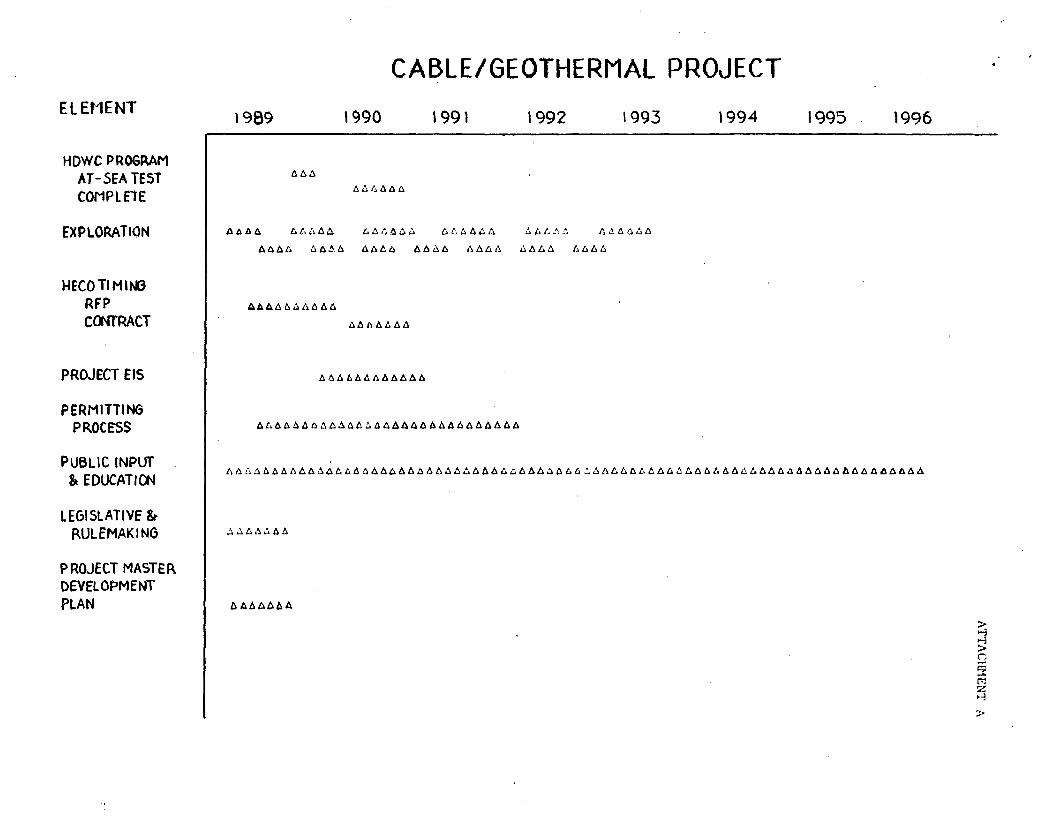
ELEMENT
HDWC PROGRAM AT-5EA TEST COMPlflE
EXPLORATION
HECO Tl M lt-13 RFP CCNfRACT
PROJECT EIS
PERMITTING PROCE'SS
PUBLIC INPUT Sl EDUCATI~
LEGISLATIVE & P.ULEMAKING
PROJECT MASTER. DEVELOPMENT PLAN
\989
CABLE/GEOTHERMAL PROJECT
1990 1991 1992 1993 \994 1995 1996
>
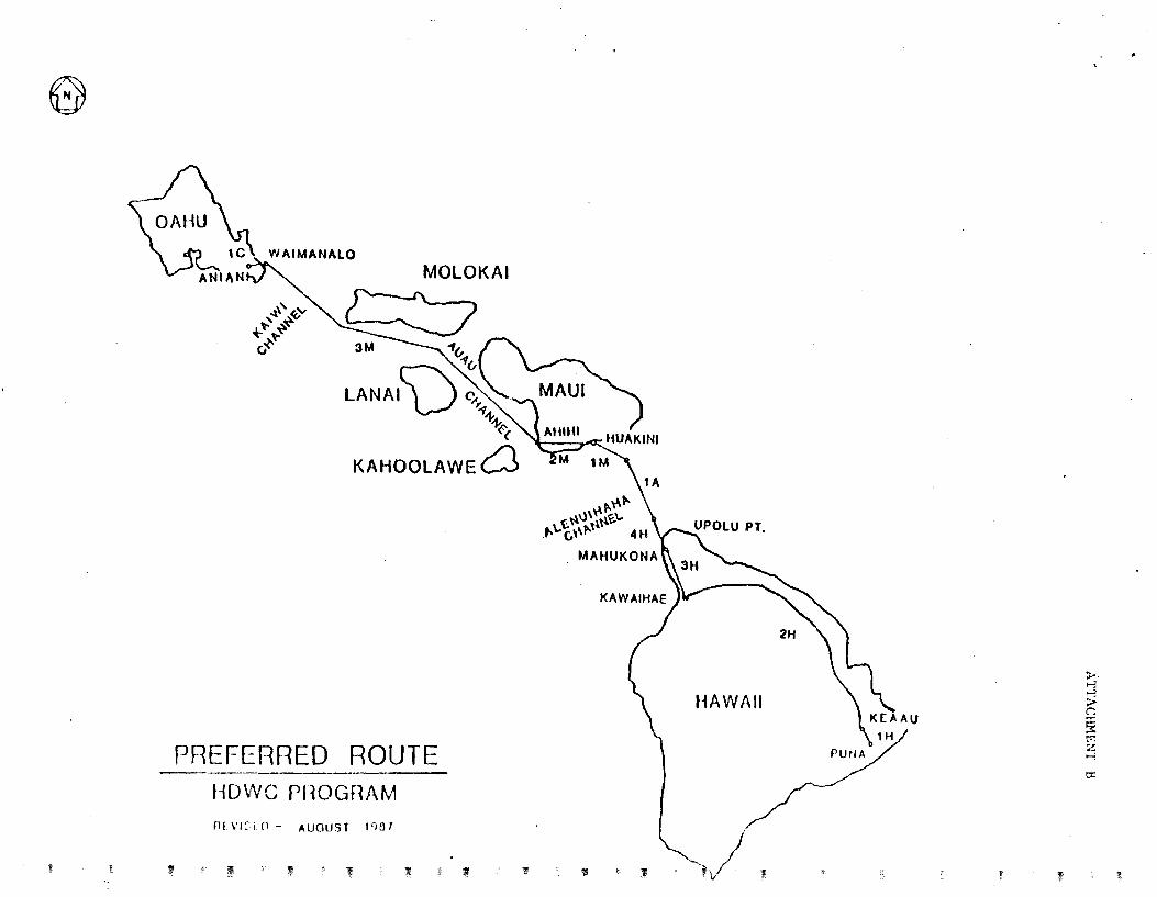
e
I
,~' ~...., t-" ~~ ~,.
(,
PREFERRED ROUTE HDvVC PHOGRAM
rl£V1::1 [l- AUGUST 1')1}1
' ' ~ "'I ' 1
tA \ ,.. "'t
~\)\"'~~\.. p.\..~''"'\ 4 H
MAHUKONA
' 11
HAWAII
.) ' 1' 11
~ ..., ....: > r. ~ rr: z .....;
0:::
'f
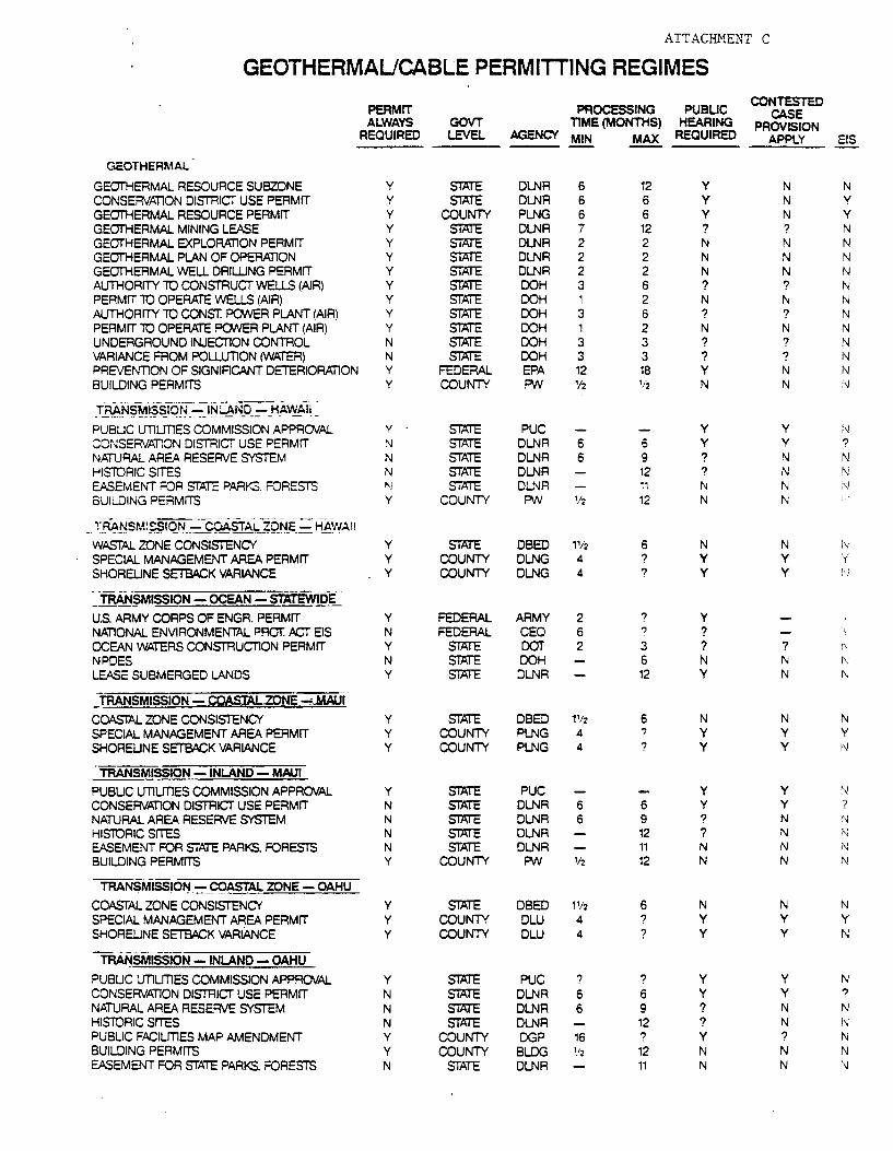
ATT ACill'1ENT c
GEOTHERMAUCABLE PERMITTING REGIMES
PERMIT PROCESSING PUBLIC CONTESTED
CASE ALWAYS GOVT TIME (MONTHS) HEARING PROVISION
REQUIRED LEVEL AGENCY MIN MAX REQUIRED APPLY ElS
GEOTHERMAL
GEOTHERMAL RESOURCE SUBZONE y STATE DLNR 6 12 y N N CONSERVATlON DISTRICi USE PERMIT y STPJE DLNR 6 6 y N y
GEOTHERMAL RESOURCE PERMIT y COUNil' PLNG 6 6 y N y
GEOTHERMAL MINING LEASE y STATE DLNR 7 12 ? ? N GEOTHERMAL EXPLORATlON PERMIT y STPJE DLNR 2 2 N N N GEOTHERMAL PLAN OF OPERATION y STATE DLNR 2 2 N N N GEOTHERMAL WELL DRIWNG PERMIT y STPJE DLNR 2 2 N N f'J AUTHORITY 10 CONSTRUCT WELLS (AIR) y STATE DOH 3 6 ? ? N PERMIT 10 OPEAPJE WELLS (AIR) y STATE DOH 1 2 N N N AUTHORITY 10 CONST. PONER PLANT (AIR) y STPJE DOH 3 6 ? ? N PERMIT 10 OPERATE PONER PLANT (AIR) y STATE DOH 1 2 N N N UNDERGROUND INJEcnON CONTROL N STATE DOH 3 3 ? ? N VARIANCE FROM POLLUTION (WATER) N STATE DOH 3 3 ? ? N PREVENTION OF SIGNIFlCANT DETERIORATlON y FEDERAL EPA 12 18 y N N BUILDING PERMITS y COUNil' FA.f\1 '12 '12 N N 1--J
_TBAN~M-,$~T6ff =~~~·'!_o __ -=-HA~Ii ~ PUBLIC UT1LmES COMMISSION APPROVAL y STPJE PUC y y N CONSERVATION DISTRIGr USE PERMIT N STATE DLNR 6 6 y y ?
NATURAL AREA RESERVE SYSTEM N STATE DLNR 6 9 ? N N HISIDRIC SITES N STATE DLNR 12 ? N N EASEMENT FOR STATE PARKS. FOREST'S "I STATE DLNR 11 N N ·~ BUILDING PERMITS y COUNil' FA.f\1 1/2 12 N N
--- -- -·----- -·--- ·-· --- ·---· ---_ T-~~SMl~IQ~.::- C9AST~.fQ~_E_.::: H~'.'w'AI!
Wt>S'rAL ZONE CONSISTENCY' y STATE DBED 1'12 6 N N i'l SPECIAL MANAGEMENT AREA PERMIT y COUNil' DLNG 4 ? y y i SHORELINE SETBACK VARIANCE y COUNil' DLNG 4 ? y y f-\;
_ TRAN§MISSION- OCEAN- STATEWIDE
U.S. ARMY CORPS OF ENGR. PERMIT y FEDERAL ARMY 2 ? y NATIONAL ENVIRONMENTAL PROT: /ICr EIS N FEDERAL CEQ 6 ? ? OCEAN WATERS CONSTRUcnON PERMIT y STATE DOT 2 3 ? ? NPDES N STATE DOH 6 N N ~J
LEASE SUBMERGED LANDS y STATE DLNR 12 y N N
TRANSMISSION - COASTAL.ZONE _,;...MALJf
COASTAL ZONE CONSISTENCY' y STATE DBED 1'12 6 N N N SPECIAL MANAGEMENT AREA PERMIT y COUNil' PLNG 4 ? y y y
SHORELINE SETBACK VARIANCE y COUNil' PLNG 4 ? y y I~
TRANSMI~ON -INLAND- MAUl
PUBLIC UT1UT1ES COMMISSION APPROVAL y STATE PUC y y ·~ CONSERVATlON DISTRICT USE PERMIT N STATE DLNR 6 6 y y ? NATURAL AREA RESERVE SYSTEM N STATE DLNR 6 9 ? N N HISIDRIC SITES N STATE DLNR 12 ? N N EASEMENT FOR STATE PARKS. FOREST'S N STATE DLNR 11 N N N BUILDING PERMITS y COUNil' FA.f\1 '12 12 N N N
----TRANSMISS!0~-~-9Q~AL ZONE- OAHU
COASTAL ZONE CONSISTENCY' y STATE DBED 11/2 6 N N N SPECIAL MANAGEMENT AREA PERMIT y COUNil' DLU 4 ? y y y SHORELINE SETBACK VARIANCE y COUNil' DLU 4 ? y y N ----------TRA~SMISSION- INLAND- OAHU
PUBLIC UT1LmES COMMISSION APPROVAL y STATE PUC ? ? y y N CONSERVATION DISTRICT USE PERMIT N STATE DLNR 6 6 y y ?
NATURAL AREA RESERVE SYSTEM N STATE DLNR 6 9 ? N N HISIDRIC SITES N STATE DLNR 12 ? N i'-J PUBLIC FACILmES MAP AMENDMENT y COUNil' DGP 16 ? y ? N BUILDING PERMITS y COUNil' BLDG '/2 12 N N N EASEMENT FOR STATE PARKS. FOREST'S N STATE DLNR 11 N N ''4
Director of Business and Economic Development 335 Merchant Street, Room 110 Honolulu, Hawaii 96813
Attention: Maurice H. Kaya, P.E. Energy Program Administrator
NOTICE OF INTENT TO RESPOND
This is to inform you that:
ORGANIZATION•$ NAME:
ADDRESS:
CONTACT PERSON:
TELEPHONE:
ATTACHMENT 0
Intends to submit a proposal to perform master planning functions for the Proposed Geothermal/Inter-Island Cable Project, in accordance with the Request for Proposals dated March 10~ 1989.
Name Date
Title
Related Documents