13 | ELECTROMAGNETIC INDUCTION Figure 13.1 The black strip found on the back of credit cards and driver’s licenses is a very thin layer of magnetic material with information stored on it. Reading and writing the information on the credit card is done with a swiping motion. The physical reason why this is necessary is called electromagnetic induction and is discussed in this chapter. Chapter Outline 13.1 Faraday’s Law 13.2 Lenz's Law 13.3 Motional Emf 13.4 Induced Electric Fields 13.5 Eddy Currents 13.6 Electric Generators and Back Emf 13.7 Applications of Electromagnetic Induction Introduction We have been considering electric fields created by fixed charge distributions and magnetic fields produced by constant currents, but electromagnetic phenomena are not restricted to these stationary situations. Most of the interesting applications of electromagnetism are, in fact, time-dependent. To investigate some of these applications, we now remove the time- independent assumption that we have been making and allow the fields to vary with time. In this and the next several chapters, you will see a wonderful symmetry in the behavior exhibited by time-varying electric and magnetic fields. Mathematically, this symmetry is expressed by an additional term in Ampère’s law and by another key equation of electromagnetism called Faraday’s law. We also discuss how moving a wire through a magnetic field produces an emf or voltage. Lastly, we describe applications of these principles, such as the card reader shown above. Chapter 13 | Electromagnetic Induction 581

Welcome message from author
This document is posted to help you gain knowledge. Please leave a comment to let me know what you think about it! Share it to your friends and learn new things together.
Transcript

13 | ELECTROMAGNETICINDUCTION
Figure 13.1 The black strip found on the back of credit cards and driver’s licenses is a very thin layer of magnetic materialwith information stored on it. Reading and writing the information on the credit card is done with a swiping motion. The physicalreason why this is necessary is called electromagnetic induction and is discussed in this chapter.
Chapter Outline
13.1 Faraday’s Law
13.2 Lenz's Law
13.3 Motional Emf
13.4 Induced Electric Fields
13.5 Eddy Currents
13.6 Electric Generators and Back Emf
13.7 Applications of Electromagnetic Induction
IntroductionWe have been considering electric fields created by fixed charge distributions and magnetic fields produced by constantcurrents, but electromagnetic phenomena are not restricted to these stationary situations. Most of the interesting applicationsof electromagnetism are, in fact, time-dependent. To investigate some of these applications, we now remove the time-independent assumption that we have been making and allow the fields to vary with time. In this and the next severalchapters, you will see a wonderful symmetry in the behavior exhibited by time-varying electric and magnetic fields.Mathematically, this symmetry is expressed by an additional term in Ampère’s law and by another key equation ofelectromagnetism called Faraday’s law. We also discuss how moving a wire through a magnetic field produces an emf orvoltage. Lastly, we describe applications of these principles, such as the card reader shown above.
Chapter 13 | Electromagnetic Induction 581

13.1 | Faraday’s Law
Learning Objectives
By the end of this section, you will be able to:
• Determine the magnetic flux through a surface, knowing the strength of the magnetic field, thesurface area, and the angle between the normal to the surface and the magnetic field
• Use Faraday’s law to determine the magnitude of induced emf in a closed loop due to changingmagnetic flux through the loop
The first productive experiments concerning the effects of time-varying magnetic fields were performed by Michael Faradayin 1831. One of his early experiments is represented in Figure 13.2. An emf is induced when the magnetic field in thecoil is changed by pushing a bar magnet into or out of the coil. Emfs of opposite signs are produced by motion in oppositedirections, and the directions of emfs are also reversed by reversing poles. The same results are produced if the coil is movedrather than the magnet—it is the relative motion that is important. The faster the motion, the greater the emf, and there is noemf when the magnet is stationary relative to the coil.
Figure 13.2 Movement of a magnet relative to a coil produces emfs as shown (a–d). The same emfs are produced if the coilis moved relative to the magnet. This short-lived emf is only present during the motion. The greater the speed, the greater themagnitude of the emf, and the emf is zero when there is no motion, as shown in (e).
Faraday also discovered that a similar effect can be produced using two circuits—a changing current in one circuit inducesa current in a second, nearby circuit. For example, when the switch is closed in circuit 1 of Figure 13.3(a), the ammeterneedle of circuit 2 momentarily deflects, indicating that a short-lived current surge has been induced in that circuit. Theammeter needle quickly returns to its original position, where it remains. However, if the switch of circuit 1 is now suddenlyopened, another short-lived current surge in the direction opposite from before is observed in circuit 2.
582 Chapter 13 | Electromagnetic Induction
This OpenStax book is available for free at http://cnx.org/content/col12074/1.3

Figure 13.3 (a) Closing the switch of circuit 1 produces a short-lived current surge in circuit 2. (b) If the switch remainsclosed, no current is observed in circuit 2. (c) Opening the switch again produces a short-lived current in circuit 2 but in theopposite direction from before.
Faraday realized that in both experiments, a current flowed in the circuit containing the ammeter only when the magneticfield in the region occupied by that circuit was changing. As the magnet of the figure was moved, the strength of itsmagnetic field at the loop changed; and when the current in circuit 1 was turned on or off, the strength of its magnetic fieldat circuit 2 changed. Faraday was eventually able to interpret these and all other experiments involving magnetic fields thatvary with time in terms of the following law:
Faraday’s Law
The emf ε induced is the negative change in the magnetic flux Φm per unit time. Any change in the magnetic field
or change in orientation of the area of the coil with respect to the magnetic field induces a voltage (emf).
The magnetic flux is a measurement of the amount of magnetic field lines through a given surface area, as seen in Figure13.4. This definition is similar to the electric flux studied earlier. This means that if we have
(13.1)Φm = ∫S
B→ · n̂dA,
then the induced emf or the voltage generated by a conductor or coil moving in a magnetic field is
(13.2)ε = − ddt∫
SB→ · n̂dA = − dΦm
dt .
The negative sign describes the direction in which the induced emf drives current around a circuit. However, that directionis most easily determined with a rule known as Lenz’s law, which we will discuss shortly.
Chapter 13 | Electromagnetic Induction 583

Figure 13.4 The magnetic flux is the amount of magneticfield lines cutting through a surface area A defined by the unit
area vector n̂ . If the angle between the unit area n̂ and
magnetic field vector B→ are parallel or antiparallel, as shown
in the diagram, the magnetic flux is the highest possible valuegiven the values of area and magnetic field.
Part (a) of Figure 13.5 depicts a circuit and an arbitrary surface S that it bounds. Notice that S is an open surface. It canbe shown that any open surface bounded by the circuit in question can be used to evaluate Φm. For example, Φm is the
same for the various surfaces S1, S2, … of part (b) of the figure.
Figure 13.5 (a) A circuit bounding an arbitrary open surface S. The planar area bounded by the circuit is notpart of S. (b) Three arbitrary open surfaces bounded by the same circuit. The value of Φm is the same for all
these surfaces.
The SI unit for magnetic flux is the weber (Wb),
1 Wb = 1 T · m2.
Occasionally, the magnetic field unit is expressed as webers per square meter ( Wb/m2 ) instead of teslas, based on this
definition. In many practical applications, the circuit of interest consists of a number N of tightly wound turns (see Figure13.6). Each turn experiences the same magnetic flux. Therefore, the net magnetic flux through the circuits is N times theflux through one turn, and Faraday’s law is written as
584 Chapter 13 | Electromagnetic Induction
This OpenStax book is available for free at http://cnx.org/content/col12074/1.3

(13.3)ε = − ddt(NΦm) = −N dΦm
dt .
Example 13.1
A Square Coil in a Changing Magnetic Field
The square coil of Figure 13.6 has sides l = 0.25 m long and is tightly wound with N = 200 turns of wire.
The resistance of the coil is R = 5.0 Ω. The coil is placed in a spatially uniform magnetic field that is directed
perpendicular to the face of the coil and whose magnitude is decreasing at a rate dB/dt = −0.040 T/s. (a) What
is the magnitude of the emf induced in the coil? (b) What is the magnitude of the current circulating through thecoil?
Figure 13.6 A square coil with N turns of wire with uniform
magnetic field B→ directed in the downward direction,
perpendicular to the coil.
Strategy
The area vector, or n̂ direction, is perpendicular to area covering the loop. We will choose this to be pointing
downward so that B→ is parallel to n̂ and that the flux turns into multiplication of magnetic field times area.
The area of the loop is not changing in time, so it can be factored out of the time derivative, leaving the magneticfield as the only quantity varying in time. Lastly, we can apply Ohm’s law once we know the induced emf to findthe current in the loop.
Solutiona. The flux through one turn is
Φm = BA = Bl2,
so we can calculate the magnitude of the emf from Faraday’s law. The sign of the emf will be discussedin the next section, on Lenz’s law:
|ε| = |−N dΦmdt | = Nl2 dB
dt= (200)(0.25 m)2(0.040 T/s) = 0.50 V.
Chapter 13 | Electromagnetic Induction 585

13.1
b. The magnitude of the current induced in the coil is
I = εR = 0.50 V
5.0 Ω = 0.10 A.
Significance
If the area of the loop were changing in time, we would not be able to pull it out of the time derivative. Since theloop is a closed path, the result of this current would be a small amount of heating of the wires until the magneticfield stops changing. This may increase the area of the loop slightly as the wires are heated.
Check Your Understanding A closely wound coil has a radius of 4.0 cm, 50 turns, and a totalresistance of 40 Ω . At what rate must a magnetic field perpendicular to the face of the coil change in order to
produce Joule heating in the coil at a rate of 2.0 mW?
13.2 | Lenz's Law
Learning Objectives
By the end of this section, you will be able to:
• Use Lenz’s law to determine the direction of induced emf whenever a magnetic flux changes
• Use Faraday’s law with Lenz’s law to determine the induced emf in a coil and in a solenoid
The direction in which the induced emf drives current around a wire loop can be found through the negative sign.However, it is usually easier to determine this direction with Lenz’s law, named in honor of its discoverer, Heinrich Lenz(1804–1865). (Faraday also discovered this law, independently of Lenz.) We state Lenz’s law as follows:
Lenz’s Law
The direction of the induced emf drives current around a wire loop to always oppose the change in magnetic flux thatcauses the emf.
Lenz’s law can also be considered in terms of conservation of energy. If pushing a magnet into a coil causes current, theenergy in that current must have come from somewhere. If the induced current causes a magnetic field opposing the increasein field of the magnet we pushed in, then the situation is clear. We pushed a magnet against a field and did work on thesystem, and that showed up as current. If it were not the case that the induced field opposes the change in the flux, themagnet would be pulled in produce a current without anything having done work. Electric potential energy would have beencreated, violating the conservation of energy.
To determine an induced emf ε , you first calculate the magnetic flux Φm and then obtain dΦm/dt. The magnitude of εis given by ε = |dΦm /dt|. Finally, you can apply Lenz’s law to determine the sense of ε . This will be developed through
examples that illustrate the following problem-solving strategy.
Problem-Solving Strategy: Lenz’s Law
To use Lenz’s law to determine the directions of induced magnetic fields, currents, and emfs:
1. Make a sketch of the situation for use in visualizing and recording directions.
2. Determine the direction of the applied magnetic field B→ .
3. Determine whether its magnetic flux is increasing or decreasing.
4. Now determine the direction of the induced magnetic field B→ . The induced magnetic field tries to reinforce a
586 Chapter 13 | Electromagnetic Induction
This OpenStax book is available for free at http://cnx.org/content/col12074/1.3
magnetic flux that is decreasing or opposes a magnetic flux that is increasing. Therefore, the induced magneticfield adds or subtracts to the applied magnetic field, depending on the change in magnetic flux.
5. Use right-hand rule 2 (RHR-2; see Magnetic Forces and Fields) to determine the direction of the induced
current I that is responsible for the induced magnetic field B→ .
6. The direction (or polarity) of the induced emf can now drive a conventional current in this direction.
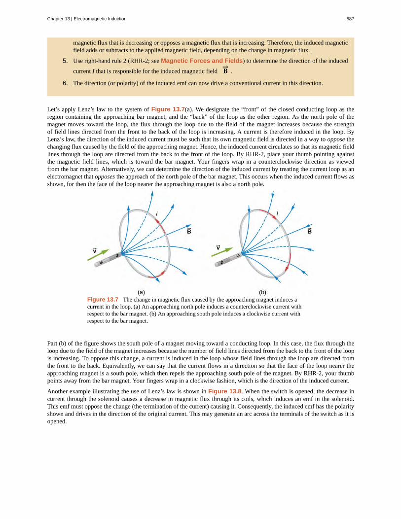
Let’s apply Lenz’s law to the system of Figure 13.7(a). We designate the “front” of the closed conducting loop as theregion containing the approaching bar magnet, and the “back” of the loop as the other region. As the north pole of themagnet moves toward the loop, the flux through the loop due to the field of the magnet increases because the strengthof field lines directed from the front to the back of the loop is increasing. A current is therefore induced in the loop. ByLenz’s law, the direction of the induced current must be such that its own magnetic field is directed in a way to oppose thechanging flux caused by the field of the approaching magnet. Hence, the induced current circulates so that its magnetic fieldlines through the loop are directed from the back to the front of the loop. By RHR-2, place your thumb pointing againstthe magnetic field lines, which is toward the bar magnet. Your fingers wrap in a counterclockwise direction as viewedfrom the bar magnet. Alternatively, we can determine the direction of the induced current by treating the current loop as anelectromagnet that opposes the approach of the north pole of the bar magnet. This occurs when the induced current flows asshown, for then the face of the loop nearer the approaching magnet is also a north pole.
Figure 13.7 The change in magnetic flux caused by the approaching magnet induces acurrent in the loop. (a) An approaching north pole induces a counterclockwise current withrespect to the bar magnet. (b) An approaching south pole induces a clockwise current withrespect to the bar magnet.
Part (b) of the figure shows the south pole of a magnet moving toward a conducting loop. In this case, the flux through theloop due to the field of the magnet increases because the number of field lines directed from the back to the front of the loopis increasing. To oppose this change, a current is induced in the loop whose field lines through the loop are directed fromthe front to the back. Equivalently, we can say that the current flows in a direction so that the face of the loop nearer theapproaching magnet is a south pole, which then repels the approaching south pole of the magnet. By RHR-2, your thumbpoints away from the bar magnet. Your fingers wrap in a clockwise fashion, which is the direction of the induced current.
Another example illustrating the use of Lenz’s law is shown in Figure 13.8. When the switch is opened, the decrease incurrent through the solenoid causes a decrease in magnetic flux through its coils, which induces an emf in the solenoid.This emf must oppose the change (the termination of the current) causing it. Consequently, the induced emf has the polarityshown and drives in the direction of the original current. This may generate an arc across the terminals of the switch as it isopened.
Chapter 13 | Electromagnetic Induction 587

13.2
13.3
Figure 13.8 (a) A solenoid connected to a source of emf. (b) Opening switch S terminates the current, which in turn inducesan emf in the solenoid. (c) A potential difference between the ends of the sharply pointed rods is produced by inducing an emfin a coil. This potential difference is large enough to produce an arc between the sharp points.
Check Your Understanding Find the direction of the induced current in the wire loop shown below asthe magnet enters, passes through, and leaves the loop.
Check Your Understanding Verify the directions of the induced currents in Figure 13.3.
Example 13.2
A Circular Coil in a Changing Magnetic Field
A magnetic field B→ is directed outward perpendicular to the plane of a circular coil of radius r = 0.50 m(Figure 13.9). The field is cylindrically symmetrical with respect to the center of the coil, and its magnitude
decays exponentially according to B = (1.5T)e−(5.0s−1)t, where B is in teslas and t is in seconds. (a) Calculate
the emf induced in the coil at the times t1 = 0, t2 = 5.0 × 10⁻² s, and t3 = 1.0 s. (b) Determine the current
in the coil at these three times if its resistance is 10 Ω.
Figure 13.9 A circular coil in a decreasing magnetic field.
588 Chapter 13 | Electromagnetic Induction
This OpenStax book is available for free at http://cnx.org/content/col12074/1.3

Strategy
Since the magnetic field is perpendicular to the plane of the coil and constant over each spot in the coil, the dot
product of the magnetic field B→ and normal to the area unit vector n̂ turns into a multiplication. The magnetic
field can be pulled out of the integration, leaving the flux as the product of the magnetic field times area. Weneed to take the time derivative of the exponential function to calculate the emf using Faraday’s law. Then we useOhm’s law to calculate the current.
Solution
a. Since B→ is perpendicular to the plane of the coil, the magnetic flux is given by
Φm = Bπr2 = (1.5e−5.0t T)π(0.50 m)2
= 1.2e−(5.0s−1)t Wb.
From Faraday’s law, the magnitude of the induced emf is
ε = |dΦmdt | = | d
dt(1.2e−(5.0s−1)t Wb)| = 6.0 e−(5.0s−1)t V.
Since B→ is directed out of the page and is decreasing, the induced current must flow counterclockwise
when viewed from above so that the magnetic field it produces through the coil also points out of thepage. For all three times, the sense of ε is counterclockwise; its magnitudes are
ε(t1) = 6.0 V; ε(t2) = 4.7 V; ε(t3) = 0.040 V.b. From Ohm’s law, the respective currents are
I(t1) = ε(t1)R = 6.0 V
10 Ω = 0.60 A;
I(t2) = 4.7 V10 Ω = 0.47 A;
and
I(t3) = 0.040 V10 Ω = 4.0 × 10⁻³ A.
Significance
An emf voltage is created by a changing magnetic flux over time. If we know how the magnetic field varies withtime over a constant area, we can take its time derivative to calculate the induced emf.
Example 13.3
Changing Magnetic Field Inside a Solenoid
The current through the windings of a solenoid with n = 2000 turns per meter is changing at a rate
dI/dt = 3.0 A/s. (See Sources of Magnetic Fields for a discussion of solenoids.) The solenoid is 50-cm long
and has a cross-sectional diameter of 3.0 cm. A small coil consisting of N = 20 closely wound turns wrapped in
a circle of diameter 1.0 cm is placed in the middle of the solenoid such that the plane of the coil is perpendicularto the central axis of the solenoid. Assuming that the infinite-solenoid approximation is valid at the location ofthe small coil, determine the magnitude of the emf induced in the coil.
Strategy
The magnetic field in the middle of the solenoid is a uniform value of µ0 nI. This field is producing a maximum
Chapter 13 | Electromagnetic Induction 589

magnetic flux through the coil as it is directed along the length of the solenoid. Therefore, the magnetic fluxthrough the coil is the product of the solenoid’s magnetic field times the area of the coil. Faraday’s law involvesa time derivative of the magnetic flux. The only quantity varying in time is the current, the rest can be pulled outof the time derivative. Lastly, we include the number of turns in the coil to determine the induced emf in the coil.
Solution
Since the field of the solenoid is given by B = µ0 nI, the flux through each turn of the small coil is
Φm = µ0 nI⎛⎝πd2
4⎞⎠,
where d is the diameter of the coil. Now from Faraday’s law, the magnitude of the emf induced in the coil is
ε = |N dΦmdt | = |Nµ0 nπd2
4dIdt |
= 20⎛⎝4π × 10−7 T · m/s⎞
⎠⎛⎝2000 m-1⎞
⎠π(0.010 m)2
4 (3.0 A/s)
= 1.2 × 10⁻⁵ V.
Significance
When the current is turned on in a vertical solenoid, as shown in Figure 13.10, the ring has an induced emf fromthe solenoid’s changing magnetic flux that opposes the change. The result is that the ring is fired vertically intothe air.
Figure 13.10 The jumping ring. When a current is turned onin the vertical solenoid, a current is induced in the metal ring.The stray field produced by the solenoid causes the ring to jumpoff the solenoid.
Visit this website (https://openstaxcollege.org/l/21flashmagind) for a demonstration of the jumping ringfrom MIT.
590 Chapter 13 | Electromagnetic Induction
This OpenStax book is available for free at http://cnx.org/content/col12074/1.3

13.3 | Motional Emf
Learning Objectives
By the end of this section, you will be able to:
• Determine the magnitude of an induced emf in a wire moving at a constant speed through amagnetic field
• Discuss examples that use motional emf, such as a rail gun and a tethered satellite
Magnetic flux depends on three factors: the strength of the magnetic field, the area through which the field lines pass, andthe orientation of the field with the surface area. If any of these quantities varies, a corresponding variation in magnetic fluxoccurs. So far, we’ve only considered flux changes due to a changing field. Now we look at another possibility: a changingarea through which the field lines pass including a change in the orientation of the area.
Two examples of this type of flux change are represented in Figure 13.11. In part (a), the flux through the rectangular loopincreases as it moves into the magnetic field, and in part (b), the flux through the rotating coil varies with the angle θ .
Figure 13.11 (a) Magnetic flux changes as a loop moves into a magnetic field; (b) magnetic flux changesas a loop rotates in a magnetic field.
It’s interesting to note that what we perceive as the cause of a particular flux change actually depends on the frame ofreference we choose. For example, if you are at rest relative to the moving coils of Figure 13.11, you would see the fluxvary because of a changing magnetic field—in part (a), the field moves from left to right in your reference frame, and inpart (b), the field is rotating. It is often possible to describe a flux change through a coil that is moving in one particularreference frame in terms of a changing magnetic field in a second frame, where the coil is stationary. However, reference-frame questions related to magnetic flux are beyond the level of this textbook. We’ll avoid such complexities by alwaysworking in a frame at rest relative to the laboratory and explain flux variations as due to either a changing field or a changingarea.
Now let’s look at a conducting rod pulled in a circuit, changing magnetic flux. The area enclosed by the circuit ‘MNOP’ ofFigure 13.12 is lx and is perpendicular to the magnetic field, so we can simplify the integration of Equation 13.1 into amultiplication of magnetic field and area. The magnetic flux through the open surface is therefore
(13.4)Φm = Blx.
Since B and l are constant and the velocity of the rod is v = dx/dt, we can now restate Faraday’s law, Equation 13.2,
for the magnitude of the emf in terms of the moving conducting rod as
Chapter 13 | Electromagnetic Induction 591

(13.5)ε = dΦmdt = Bldx
dt = Blv.
The current induced in the circuit is the emf divided by the resistance or
I = BlvR .
Furthermore, the direction of the induced emf satisfies Lenz’s law, as you can verify by inspection of the figure.
This calculation of motionally induced emf is not restricted to a rod moving on conducting rails. With F→ = q v→ × B→
as the starting point, it can be shown that ε = −dΦm /dt holds for any change in flux caused by the motion of a conductor.
We saw in Faraday’s Law that the emf induced by a time-varying magnetic field obeys this same relationship, which isFaraday’s law. Thus Faraday’s law holds for all flux changes, whether they are produced by a changing magnetic field, bymotion, or by a combination of the two.
Figure 13.12 A conducting rod is pushed to the right atconstant velocity. The resulting change in the magnetic fluxinduces a current in the circuit.
From an energy perspective, F→ a produces power Fa v, and the resistor dissipates power I 2 R . Since the rod is moving
at constant velocity, the applied force Fa must balance the magnetic force Fm = IlB on the rod when it is carrying the
induced current I. Thus the power produced is
(13.6)Fa v = IlBv = BlvR · lBv = l2 B2 v2
R .
The power dissipated is
(13.7)P = I 2 R = ⎛
⎝BlvR
⎞⎠2
R = l2 B2 v2
R .
In satisfying the principle of energy conservation, the produced and dissipated powers are equal.
This principle can be seen in the operation of a rail gun. A rail gun is an electromagnetic projectile launcher that uses anapparatus similar to Figure 13.12 and is shown in schematic form in Figure 13.13. The conducting rod is replaced with aprojectile or weapon to be fired. So far, we’ve only heard about how motion causes an emf. In a rail gun, the optimal shuttingoff/ramping down of a magnetic field decreases the flux in between the rails, causing a current to flow in the rod (armature)that holds the projectile. This current through the armature experiences a magnetic force and is propelled forward. Railguns, however, are not used widely in the military due to the high cost of production and high currents: Nearly one millionamps is required to produce enough energy for a rail gun to be an effective weapon.
592 Chapter 13 | Electromagnetic Induction
This OpenStax book is available for free at http://cnx.org/content/col12074/1.3

Figure 13.13 Current through two rails drives a conductive projectile forward by the magneticforce created.
We can calculate a motionally induced emf with Faraday’s law even when an actual closed circuit is not present. Wesimply imagine an enclosed area whose boundary includes the moving conductor, calculate Φm , and then find the emf
from Faraday’s law. For example, we can let the moving rod of Figure 13.14 be one side of the imaginary rectangular arearepresented by the dashed lines. The area of the rectangle is lx, so the magnetic flux through it is Φm = Blx. Differentiating
this equation, we obtain
(13.8)dΦmdt = Bldx
dt = Blv,
which is identical to the potential difference between the ends of the rod that we determined earlier.
Figure 13.14 With the imaginary rectangle shown, we canuse Faraday’s law to calculate the induced emf in the movingrod.
Motional emfs in Earth’s weak magnetic field are not ordinarily very large, or we would notice voltage along metal rods,such as a screwdriver, during ordinary motions. For example, a simple calculation of the motional emf of a 1.0-m rodmoving at 3.0 m/s perpendicular to the Earth’s field gives
emf = Bℓv = (5.0 × 10⁻⁵ T)(1.0 m)(3.0 m/s) = 150µV.
This small value is consistent with experience. There is a spectacular exception, however. In 1992 and 1996, attempts weremade with the space shuttle to create large motional emfs. The tethered satellite was to be let out on a 20-km length ofwire, as shown in Figure 13.15, to create a 5-kV emf by moving at orbital speed through Earth’s field. This emf couldbe used to convert some of the shuttle’s kinetic and potential energy into electrical energy if a complete circuit could bemade. To complete the circuit, the stationary ionosphere was to supply a return path through which current could flow. (Theionosphere is the rarefied and partially ionized atmosphere at orbital altitudes. It conducts because of the ionization. Theionosphere serves the same function as the stationary rails and connecting resistor in Figure 13.13, without which there
Chapter 13 | Electromagnetic Induction 593

would not be a complete circuit.) Drag on the current in the cable due to the magnetic force F = IℓBsin θ does the work
that reduces the shuttle’s kinetic and potential energy, and allows it to be converted into electrical energy. Both tests wereunsuccessful. In the first, the cable hung up and could only be extended a couple of hundred meters; in the second, the cablebroke when almost fully extended. Example 13.4 indicates feasibility in principle.
Figure 13.15 Motional emf as electrical power conversion forthe space shuttle was the motivation for the tethered satelliteexperiment. A 5-kV emf was predicted to be induced in the20-km tether while moving at orbital speed in Earth’s magneticfield. The circuit is completed by a return path through thestationary ionosphere.
Example 13.4
Calculating the Large Motional Emf of an Object in Orbit
Calculate the motional emf induced along a 20.0-km conductor moving at an orbital speed of 7.80 km/s
perpendicular to Earth’s 5.00 × 10⁻⁵ T magnetic field.
Strategy
This is a great example of using the equation motional ε = Bℓv.
Solution
Entering the given values into ε = Bℓv gives
ε = Bℓv= (5.00 × 10⁻⁵ T)(2.00 × 10⁴ m)(7.80 × 10³ m/s)= 7.80 × 10³ V.
Significance
The value obtained is greater than the 5-kV measured voltage for the shuttle experiment, since the actual orbitalmotion of the tether is not perpendicular to Earth’s field. The 7.80-kV value is the maximum emf obtained whenθ = 90° and so sin θ = 1.
594 Chapter 13 | Electromagnetic Induction
This OpenStax book is available for free at http://cnx.org/content/col12074/1.3

Example 13.5
A Metal Rod Rotating in a Magnetic Field
Part (a) of Figure 13.16 shows a metal rod OS that is rotating in a horizontal plane around point O. The rod
slides along a wire that forms a circular arc PST of radius r. The system is in a constant magnetic field B→ that
is directed out of the page. (a) If you rotate the rod at a constant angular velocity ω , what is the current I in
the closed loop OPSO? Assume that the resistor R furnishes all of the resistance in the closed loop. (b) Calculatethe work per unit time that you do while rotating the rod and show that it is equal to the power dissipated in theresistor.
Figure 13.16 (a) The end of a rotating metal rod slides along a circular wire in a horizontal plane. (b) Theinduced current in the rod. (c) The magnetic force on an infinitesimal current segment.
Strategy
The magnetic flux is the magnetic field times the area of the quarter circle or A = r2 θ/2. When finding the emf
through Faraday’s law, all variables are constant in time but θ , with ω = dθ/dt. To calculate the work per unit
time, we know this is related to the torque times the angular velocity. The torque is calculated by knowing theforce on a rod and integrating it over the length of the rod.
Solution
a. From geometry, the area of the loop OPSO is A = r2 θ2 . Hence, the magnetic flux through the loop is
Φm = BA = Br2 θ2 .
Differentiating with respect to time and using ω = dθ/dt, we have
ε = |dΦmdt | = Br2 ω
2 .
When divided by the resistance R of the loop, this yields for the magnitude of the induced current
I = εR = Br2 ω
2R .
As θ increases, so does the flux through the loop due to B→ . To counteract this increase, the magnetic
field due to the induced current must be directed into the page in the region enclosed by the loop.Therefore, as part (b) of Figure 13.16 illustrates, the current circulates clockwise.
b. You rotate the rod by exerting a torque on it. Since the rod rotates at constant angular velocity, thistorque is equal and opposite to the torque exerted on the current in the rod by the original magneticfield. The magnetic force on the infinitesimal segment of length dx shown in part (c) of Figure 13.16 is
Chapter 13 | Electromagnetic Induction 595

dFm = IBdx, so the magnetic torque on this segment is
dτm = x · dFm = IBxdx.
The net magnetic torque on the rod is then
τm = ∫0
rdτm = IB⌠
⌡0
rx dx = 1
2IBr2.
The torque τ that you exert on the rod is equal and opposite to τm, and the work that you do when the
rod rotates through an angle dθ is dW = τdθ. Hence, the work per unit time that you do on the rod is
dWdt = τdθ
dt = 12IBr2 dθ
dt = 12
⎛⎝Br2 ω
2R⎞⎠Br2 ω = B2 r4 ω2
4R ,
where we have substituted for I. The power dissipated in the resister is P = I 2 R , which can be written
as
P = ⎛⎝Br2 ω
2R⎞⎠
2R = B2 r4 ω2
4R .
Therefore, we see that
P = dWdt .
Hence, the power dissipated in the resistor is equal to the work per unit time done in rotating the rod.
Significance
An alternative way of looking at the induced emf from Faraday’s law is to integrate in space instead of time. Thesolution, however, would be the same. The motional emf is
|ε| = ∫ Bvdl.
The velocity can be written as the angular velocity times the radius and the differential length written as dr.Therefore,
|ε| = B⌠⌡
vdr = Bω∫0
lrdr = 1
2Bωl2,
which is the same solution as before.
Example 13.6
A Rectangular Coil Rotating in a Magnetic Field
A rectangular coil of area A and N turns is placed in a uniform magnetic field B→ = B j^
, as shown in Figure
13.17. The coil is rotated about the z-axis through its center at a constant angular velocity ω. Obtain an
expression for the induced emf in the coil.
596 Chapter 13 | Electromagnetic Induction
This OpenStax book is available for free at http://cnx.org/content/col12074/1.3

Figure 13.17 A rectangular coil rotating in a uniformmagnetic field.
Strategy
According to the diagram, the angle between the perpendicular to the surface ( n̂ ) and the magnetic field ( B→ )
is θ . The dot product of B→ · n̂ simplifies to only the cos θ component of the magnetic field, namely where
the magnetic field projects onto the unit area vector n̂ . The magnitude of the magnetic field and the area of
the loop are fixed over time, which makes the integration simplify quickly. The induced emf is written out usingFaraday’s law.
Solution
When the coil is in a position such that its normal vector n̂ makes an angle θ with the magnetic field B→ ,the magnetic flux through a single turn of the coil is
Φm = ∫S
B→ · n̂dA = BAcos θ.
From Faraday’s law, the emf induced in the coil is
ε = −N dΦmdt = NBAsin θdθ
dt .
The constant angular velocity is ω = dθ/dt. The angle θ represents the time evolution of the angular velocity
or ωt . This is changes the function to time space rather than θ . The induced emf therefore varies sinusoidally
with time according to
ε = ε0 sin ωt,
where ε0 = NBAω.
Significance
If the magnetic field strength or area of the loop were also changing over time, these variables wouldn’t be ableto be pulled out of the time derivative to simply the solution as shown. This example is the basis for an electricgenerator, as we will give a full discussion in Applications of Newton’s Law (http://cnx.org/content/
Chapter 13 | Electromagnetic Induction 597

13.4
13.5
m58302/latest/) .
Check Your Understanding Shown below is a rod of length l that is rotated counterclockwise around
the axis through O by the torque due to m g→ . Assuming that the rod is in a uniform magnetic field B→ , what
is the emf induced between the ends of the rod when its angular velocity is ω ? Which end of the rod is at a
higher potential?
Check Your Understanding A rod of length 10 cm moves at a speed of 10 m/s perpendicularly througha 1.5-T magnetic field. What is the potential difference between the ends of the rod?
13.4 | Induced Electric Fields
Learning Objectives
By the end of this section, you will be able to:
• Connect the relationship between an induced emf from Faraday’s law to an electric field,thereby showing that a changing magnetic flux creates an electric field
• Solve for the electric field based on a changing magnetic flux in time
The fact that emfs are induced in circuits implies that work is being done on the conduction electrons in the wires. What canpossibly be the source of this work? We know that it’s neither a battery nor a magnetic field, for a battery does not have tobe present in a circuit where current is induced, and magnetic fields never do work on moving charges. The answer is that
the source of the work is an electric field E→ that is induced in the wires. The work done by E→ in moving a unit charge
completely around a circuit is the induced emf ε; that is,
(13.9)ε = ∮ E→ · d l→ ,
where∮
represents the line integral around the circuit. Faraday’s law can be written in terms of the induced electric fieldas
(13.10)∮ E→ · d l→ = − dΦmdt .
There is an important distinction between the electric field induced by a changing magnetic field and the electrostatic field
598 Chapter 13 | Electromagnetic Induction
This OpenStax book is available for free at http://cnx.org/content/col12074/1.3

produced by a fixed charge distribution. Specifically, the induced electric field is nonconservative because it does net workin moving a charge over a closed path, whereas the electrostatic field is conservative and does no net work over a closedpath. Hence, electric potential can be associated with the electrostatic field, but not with the induced field. The followingequations represent the distinction between the two types of electric field:
(13.11)∮ E→ · d l→ ≠ 0 (induced);
∮ E→ · d l→ = 0 (electrostatic).
Our results can be summarized by combining these equations:
(13.12)ε = ∮ E→ · d l→ = −dΦmdt .
Example 13.7
Induced Electric Field in a Circular Coil
What is the induced electric field in the circular coil of Example 13.2 (and Figure 13.9) at the three timesindicated?
Strategy
Using cylindrical symmetry, the electric field integral simplifies into the electric field times the circumference ofa circle. Since we already know the induced emf, we can connect these two expressions by Faraday’s law to solvefor the induced electric field.
Solution
The induced electric field in the coil is constant in magnitude over the cylindrical surface, similar to how
Ampere’s law problems with cylinders are solved. Since E→ is tangent to the coil,
∮ E→ · d l→ = ∮ Edl = 2πrE.
When combined with Equation 13.12, this gives
E = ε2πr .
The direction of ε is counterclockwise, and E→ circulates in the same direction around the coil. The values of
E are
E(t1) = 6.0 V2π (0.50 m) = 1.9 V/m;
E(t2) = 4.7 V2π (0.50 m) = 1.5 V/m;
E(t3) = 0.040 V2π (0.50 m) = 0.013 V/m.
Significance
When the magnetic flux through a circuit changes, a nonconservative electric field is induced, which drivescurrent through the circuit. But what happens if dB/dt ≠ 0 in free space where there isn’t a conducting path?
The answer is that this case can be treated as if a conducting path were present; that is, nonconservative electricfields are induced wherever dB/dt ≠ 0, whether or not there is a conducting path present.
These nonconservative electric fields always satisfy Equation 13.12. For example, if the circular coil of Figure13.9 were removed, an electric field in free space at r = 0.50 m would still be directed counterclockwise, and its
Chapter 13 | Electromagnetic Induction 599

magnitude would still be 1.9 V/m at t = 0 , 1.5 V/m at t = 5.0 × 10⁻² s, etc. The existence of induced electric
fields is certainly not restricted to wires in circuits.
Example 13.8
Electric Field Induced by the Changing Magnetic Field of a Solenoid
Part (a) of Figure 13.18 shows a long solenoid with radius R and n turns per unit length; its current decreaseswith time according to I = I0 e−αt. What is the magnitude of the induced electric field at a point a distance r
from the central axis of the solenoid (a) when r > R and (b) when r < R [see part (b) of Figure 13.18]. (c)
What is the direction of the induced field at both locations? Assume that the infinite-solenoid approximation isvalid throughout the regions of interest.
Figure 13.18 (a) The current in a long solenoid is decreasing exponentially. (b) A cross-sectionalview of the solenoid from its left end. The cross-section shown is near the middle of the solenoid. Anelectric field is induced both inside and outside the solenoid.
Strategy
Using the formula for the magnetic field inside an infinite solenoid and Faraday’s law, we calculate the inducedemf. Since we have cylindrical symmetry, the electric field integral reduces to the electric field times thecircumference of the integration path. Then we solve for the electric field.
Solutiona. The magnetic field is confined to the interior of the solenoid where
B = µ0 nI = µ0 nI0 e−αt.
Thus, the magnetic flux through a circular path whose radius r is greater than R, the solenoid radius, is
Φm = BA = µ0 nI0 πR2 e−αt.
The induced field E→ is tangent to this path, and because of the cylindrical symmetry of the system, its
magnitude is constant on the path. Hence, we have
600 Chapter 13 | Electromagnetic Induction
This OpenStax book is available for free at http://cnx.org/content/col12074/1.3

13.6
13.7
|∮ E→ · d l→ | = |dΦmdt |,
E(2πr) = | ddt(µ0 nI0 πR2 e−αt)| = αµ0 nI0 πR2 e−αt,
E = αµ0 nI0 R2
2r e−αt (r > R).
b. For a path of radius r inside the solenoid, Φm = Bπr2, so
E(2πr) = | ddt(µ0 nI0 πr2 e−αt)| = αµ0 nI0 πr2 e−αt,
and the induced field is
E = αµ0 nI0 r2 e−αt (r < R).
c. The magnetic field points into the page as shown in part (b) and is decreasing. If either of the circularpaths were occupied by conducting rings, the currents induced in them would circulate as shown, inconformity with Lenz’s law. The induced electric field must be so directed as well.
Significance
In part (b), note that | E→ | increases with r inside and decreases as 1/r outside the solenoid, as shown in Figure
13.19.
Figure 13.19 The electric field vs. distance r. When r < R,the electric field rises linearly, whereas when r > R, the
electric field falls of proportional to 1/r.
Check Your Understanding Suppose that the coil of Example 13.2 is a square rather than circular.Can Equation 13.12 be used to calculate (a) the induced emf and (b) the induced electric field?
Check Your Understanding What is the magnitude of the induced electric field in Example 13.8 at
t = 0 if r = 6.0 cm, R = 2.0 cm, n = 2000 turns per meter, I0 = 2.0 A, and α = 200 s−1?
Chapter 13 | Electromagnetic Induction 601

13.8
13.9
Check Your Understanding The magnetic field shown below is confined to the cylindrical region
shown and is changing with time. Identify those paths for which ε = ∮ E→ · d l→ ≠ 0.
Check Your Understanding A long solenoid of cross-sectional area 5.0 cm2 is wound with 25 turns
of wire per centimeter. It is placed in the middle of a closely wrapped coil of 10 turns and radius 25 cm, asshown below. (a) What is the emf induced in the coil when the current through the solenoid is decreasing at arate dI/dt = −0.20 A/s? (b) What is the electric field induced in the coil?
13.5 | Eddy Currents
Learning Objectives
By the end of this section, you will be able to:
• Explain how eddy currents are created in metals
• Describe situations where eddy currents are beneficial and where they are not helpful
As discussed two sections earlier, a motional emf is induced when a conductor moves in a magnetic field or when a magneticfield moves relative to a conductor. If motional emf can cause a current in the conductor, we refer to that current as an eddycurrent.
Magnetic DampingEddy currents can produce significant drag, called magnetic damping, on the motion involved. Consider the apparatusshown in Figure 13.20, which swings a pendulum bob between the poles of a strong magnet. (This is another favoritephysics demonstration.) If the bob is metal, significant drag acts on the bob as it enters and leaves the field, quickly damping
602 Chapter 13 | Electromagnetic Induction
This OpenStax book is available for free at http://cnx.org/content/col12074/1.3

the motion. If, however, the bob is a slotted metal plate, as shown in part (b) of the figure, the magnet produces a muchsmaller effect. There is no discernible effect on a bob made of an insulator. Why does drag occur in both directions, and arethere any uses for magnetic drag?
Figure 13.20 A common physics demonstration device for exploring eddycurrents and magnetic damping. (a) The motion of a metal pendulum bobswinging between the poles of a magnet is quickly damped by the action ofeddy currents. (b) There is little effect on the motion of a slotted metal bob,implying that eddy currents are made less effective. (c) There is also nomagnetic damping on a nonconducting bob, since the eddy currents areextremely small.
Figure 13.21 shows what happens to the metal plate as it enters and leaves the magnetic field. In both cases, it experiencesa force opposing its motion. As it enters from the left, flux increases, setting up an eddy current (Faraday’s law) in thecounterclockwise direction (Lenz’s law), as shown. Only the right-hand side of the current loop is in the field, so anunopposed force acts on it to the left (RHR-1). When the metal plate is completely inside the field, there is no eddy currentif the field is uniform, since the flux remains constant in this region. But when the plate leaves the field on the right, fluxdecreases, causing an eddy current in the clockwise direction that, again, experiences a force to the left, further slowing themotion. A similar analysis of what happens when the plate swings from the right toward the left shows that its motion isalso damped when entering and leaving the field.
Figure 13.21 A more detailed look at the conducting plate passingbetween the poles of a magnet. As it enters and leaves the field, the changein flux produces an eddy current. Magnetic force on the current loopopposes the motion. There is no current and no magnetic drag when theplate is completely inside the uniform field.
Chapter 13 | Electromagnetic Induction 603

When a slotted metal plate enters the field (Figure 13.22), an emf is induced by the change in flux, but it is less effectivebecause the slots limit the size of the current loops. Moreover, adjacent loops have currents in opposite directions, and theireffects cancel. When an insulating material is used, the eddy current is extremely small, so magnetic damping on insulatorsis negligible. If eddy currents are to be avoided in conductors, then they must be slotted or constructed of thin layers ofconducting material separated by insulating sheets.
Figure 13.22 Eddy currents induced in a slotted metal plateentering a magnetic field form small loops, and the forces onthem tend to cancel, thereby making magnetic drag almost zero.
Applications of Magnetic DampingOne use of magnetic damping is found in sensitive laboratory balances. To have maximum sensitivity and accuracy, thebalance must be as friction-free as possible. But if it is friction-free, then it will oscillate for a very long time. Magneticdamping is a simple and ideal solution. With magnetic damping, drag is proportional to speed and becomes zero at zerovelocity. Thus, the oscillations are quickly damped, after which the damping force disappears, allowing the balance to bevery sensitive (Figure 13.23). In most balances, magnetic damping is accomplished with a conducting disc that rotates ina fixed field.
Figure 13.23 Magnetic damping of this sensitive balance slows its oscillations. SinceFaraday’s law of induction gives the greatest effect for the most rapid change, damping isgreatest for large oscillations and goes to zero as the motion stops.
Since eddy currents and magnetic damping occur only in conductors, recycling centers can use magnets to separate metals
604 Chapter 13 | Electromagnetic Induction
This OpenStax book is available for free at http://cnx.org/content/col12074/1.3

from other materials. Trash is dumped in batches down a ramp, beneath which lies a powerful magnet. Conductors in thetrash are slowed by magnetic damping while nonmetals in the trash move on, separating from the metals (Figure 13.24).This works for all metals, not just ferromagnetic ones. A magnet can separate out the ferromagnetic materials alone byacting on stationary trash.
Figure 13.24 Metals can be separated from other trash by magnetic drag. Eddy currents and magnetic drag are created inthe metals sent down this ramp by the powerful magnet beneath it. Nonmetals move on.
Other major applications of eddy currents appear in metal detectors and braking systems in trains and roller coasters.Portable metal detectors (Figure 13.25) consist of a primary coil carrying an alternating current and a secondary coil inwhich a current is induced. An eddy current is induced in a piece of metal close to the detector, causing a change in theinduced current within the secondary coil. This can trigger some sort of signal, such as a shrill noise.
Figure 13.25 A soldier in Iraq uses a metal detector to searchfor explosives and weapons. (credit: U.S. Army)
Braking using eddy currents is safer because factors such as rain do not affect the braking and the braking is smoother.However, eddy currents cannot bring the motion to a complete stop, since the braking force produced decreases as speed isreduced. Thus, speed can be reduced from say 20 m/s to 5 m/s, but another form of braking is needed to completely stopthe vehicle. Generally, powerful rare-earth magnets such as neodymium magnets are used in roller coasters. Figure 13.26
Chapter 13 | Electromagnetic Induction 605

shows rows of magnets in such an application. The vehicle has metal fins (normally containing copper) that pass throughthe magnetic field, slowing the vehicle down in much the same way as with the pendulum bob shown in Figure 13.20.
Figure 13.26 The rows of rare-earth magnets (protruding horizontally) are used for magneticbraking in roller coasters. (credit: Stefan Scheer)
Induction cooktops have electromagnets under their surface. The magnetic field is varied rapidly, producing eddy currentsin the base of the pot, causing the pot and its contents to increase in temperature. Induction cooktops have high efficienciesand good response times but the base of the pot needs to be conductors, such as iron or steel, for induction to work.
13.6 | Electric Generators and Back Emf
Learning Objectives
By the end of this section, you will be able to:
• Explain how an electric generator works
• Determine the induced emf in a loop at any time interval, rotating at a constant rate in amagnetic field
• Show that rotating coils have an induced emf; in motors this is called back emf because itopposes the emf input to the motor
A variety of important phenomena and devices can be understood with Faraday’s law. In this section, we examine two ofthese.
Electric GeneratorsElectric generators induce an emf by rotating a coil in a magnetic field, as briefly discussed in Motional Emf. We nowexplore generators in more detail. Consider the following example.
606 Chapter 13 | Electromagnetic Induction
This OpenStax book is available for free at http://cnx.org/content/col12074/1.3

Example 13.9
Calculating the Emf Induced in a Generator Coil
The generator coil shown in Figure 13.27 is rotated through one-fourth of a revolution (from θ = 0° to
θ = 90°) in 15.0 ms. The 200-turn circular coil has a 5.00-cm radius and is in a uniform 0.80-T magnetic field.
What is the emf induced?
Figure 13.27 When this generator coil is rotated through one-fourth of a revolution, the magnetic flux Φm changes from its
maximum to zero, inducing an emf.
Strategy
Faraday’s law of induction is used to find the emf induced:
ε = −N dΦmdt .
We recognize this situation as the same one in Example 13.6. According to the diagram, the projection of the
surface normal vector n̂ to the magnetic field is initially cos θ, and this is inserted by the definition of the dot
product. The magnitude of the magnetic field and area of the loop are fixed over time, which makes the integrationsimplify quickly. The induced emf is written out using Faraday’s law:
ε = NBA sin θdθdt .
Chapter 13 | Electromagnetic Induction 607

Solution
We are given that N = 200, B = 0.80 T, θ = 90° , dθ = 90° = π/2 , and dt = 15.0 ms. The area of the
loop is
A = πr2 = (3.14)(0.0500 m)2 = 7.85 × 10⁻³ m2.
Entering this value gives
ε = (200)(0.80 T)(7.85 × 10⁻³ m2)sin (90°) π/215.0 × 10−3 s
= 131 V.
Significance
This is a practical average value, similar to the 120 V used in household power.
The emf calculated in Example 13.9 is the average over one-fourth of a revolution. What is the emf at any given instant?It varies with the angle between the magnetic field and a perpendicular to the coil. We can get an expression for emf asa function of time by considering the motional emf on a rotating rectangular coil of width w and height l in a uniformmagnetic field, as illustrated in Figure 13.28.
Figure 13.28 A generator with a single rectangular coilrotated at constant angular velocity in a uniform magnetic fieldproduces an emf that varies sinusoidally in time. Note thegenerator is similar to a motor, except the shaft is rotated toproduce a current rather than the other way around.
Charges in the wires of the loop experience the magnetic force, because they are moving in a magnetic field. Charges in thevertical wires experience forces parallel to the wire, causing currents. But those in the top and bottom segments feel a forceperpendicular to the wire, which does not cause a current. We can thus find the induced emf by considering only the sidewires. Motional emf is given to be ε = Blv , where the velocity v is perpendicular to the magnetic field B. Here the velocity
is at an angle θ with B, so that its component perpendicular to B is v sin θ (see Figure 13.28). Thus, in this case, the emf
induced on each side is ε = Blv sin θ , and they are in the same direction. The total emf around the loop is then
(13.13)ε = 2Blv sin θ.
This expression is valid, but it does not give emf as a function of time. To find the time dependence of emf, we assume thecoil rotates at a constant angular velocity ω . The angle θ is related to angular velocity by θ = ωt, so that
(13.14)ε = 2Blv sin(ωt).
Now, linear velocity v is related to angular velocity ω by v = rω. Here, r = w/2, so that v = (w/2)ω, and
(13.15)ε = 2Blw2 ω sin ωt = (lw)Bω sin ωt.
Noting that the area of the loop is A = lw, and allowing for N loops, we find that
608 Chapter 13 | Electromagnetic Induction
This OpenStax book is available for free at http://cnx.org/content/col12074/1.3

(13.16)ε = NBAω sin(ωt).
This is the emf induced in a generator coil of N turns and area A rotating at a constant angular velocity ω in a uniform
magnetic field B. This can also be expressed as
(13.17)ε = ε0 sin ωt,
where
(13.18)ε0 = NABω
is the peak emf, since the maximum value of sin(wt) = 1 . Note that the frequency of the oscillation is f = ω/2π and the
period is T = 1/ f = 2π/ ω. Figure 13.29 shows a graph of emf as a function of time, and it now seems reasonable that
ac voltage is sinusoidal.
Figure 13.29 The emf of a generator is sent to a light bulb with the system of rings andbrushes shown. The graph gives the emf of the generator as a function of time, where ε0 is
the peak emf. The period is T = 1/ f = 2π/ ω, where f is the frequency.
The fact that the peak emf is ε0 = NBAω makes good sense. The greater the number of coils, the larger their area, and the
stronger the field, the greater the output voltage. It is interesting that the faster the generator is spun (greater ω ), the greater
the emf. This is noticeable on bicycle generators—at least the cheaper varieties.
Figure 13.30 shows a scheme by which a generator can be made to produce pulsed dc. More elaborate arrangements ofmultiple coils and split rings can produce smoother dc, although electronic rather than mechanical means are usually usedto make ripple-free dc.
Chapter 13 | Electromagnetic Induction 609

Figure 13.30 Split rings, called commutators, produce a pulsed dc emf output in thisconfiguration.
In real life, electric generators look a lot different from the figures in this section, but the principles are the same. The sourceof mechanical energy that turns the coil can be falling water (hydropower), steam produced by the burning of fossil fuels, orthe kinetic energy of wind. Figure 13.31 shows a cutaway view of a steam turbine; steam moves over the blades connectedto the shaft, which rotates the coil within the generator. The generation of electrical energy from mechanical energy is thebasic principle of all power that is sent through our electrical grids to our homes.
Figure 13.31 Steam turbine/generator. The steam produced by burning coal impacts theturbine blades, turning the shaft, which is connected to the generator.
Generators illustrated in this section look very much like the motors illustrated previously. This is not coincidental. In fact,a motor becomes a generator when its shaft rotates. Certain early automobiles used their starter motor as a generator. In thenext section, we further explore the action of a motor as a generator.
610 Chapter 13 | Electromagnetic Induction
This OpenStax book is available for free at http://cnx.org/content/col12074/1.3

Back EmfGenerators convert mechanical energy into electrical energy, whereas motors convert electrical energy into mechanicalenergy. Thus, it is not surprising that motors and generators have the same general construction. A motor works by sendinga current through a loop of wire located in a magnetic field. As a result, the magnetic field exerts torque on the loop.This rotates a shaft, thereby extracting mechanical work out of the electrical current sent in initially. (Refer to Forceand Torque on a Current Loop for a discussion on motors that will help you understand more about them beforeproceeding.)
When the coil of a motor is turned, magnetic flux changes through the coil, and an emf (consistent with Faraday’s law) isinduced. The motor thus acts as a generator whenever its coil rotates. This happens whether the shaft is turned by an externalinput, like a belt drive, or by the action of the motor itself. That is, when a motor is doing work and its shaft is turning, anemf is generated. Lenz’s law tells us the emf opposes any change, so that the input emf that powers the motor is opposed bythe motor’s self-generated emf, called the back emf of the motor (Figure 13.32).
Figure 13.32 The coil of a dc motor is represented as aresistor in this schematic. The back emf is represented as avariable emf that opposes the emf driving the motor. Back emf iszero when the motor is not turning and increases proportionallyto the motor’s angular velocity.
The generator output of a motor is the difference between the supply voltage and the back emf. The back emf is zero whenthe motor is first turned on, meaning that the coil receives the full driving voltage and the motor draws maximum currentwhen it is on but not turning. As the motor turns faster, the back emf grows, always opposing the driving emf, and reducesboth the voltage across the coil and the amount of current it draws. This effect is noticeable in many common situations.When a vacuum cleaner, refrigerator, or washing machine is first turned on, lights in the same circuit dim briefly due to theIR drop produced in feeder lines by the large current drawn by the motor.
When a motor first comes on, it draws more current than when it runs at its normal operating speed. When a mechanicalload is placed on the motor, like an electric wheelchair going up a hill, the motor slows, the back emf drops, more currentflows, and more work can be done. If the motor runs at too low a speed, the larger current can overheat it (via resistive
power in the coil, P = I 2 R), perhaps even burning it out. On the other hand, if there is no mechanical load on the motor,
it increases its angular velocity ω until the back emf is nearly equal to the driving emf. Then the motor uses only enough
energy to overcome friction.
Eddy currents in iron cores of motors can cause troublesome energy losses. These are usually minimized by constructingthe cores out of thin, electrically insulated sheets of iron. The magnetic properties of the core are hardly affected by thelamination of the insulating sheet, while the resistive heating is reduced considerably. Consider, for example, the motorcoils represented in Figure 13.32. The coils have an equivalent resistance of 0.400 Ω and are driven by an emf of 48.0 V.
Shortly after being turned on, they draw a current
I = V /R = (48.0 V)/(0.400 Ω) = 120 A
and thus dissipate P = I 2 R = 5.76 kW of energy as heat transfer. Under normal operating conditions for this motor,
suppose the back emf is 40.0 V. Then at operating speed, the total voltage across the coils is 8.0 V (48.0 V minus the 40.0V back emf), and the current drawn is
I = V /R = (8.0 V)/(0.400 Ω) = 20 A .
Under normal load, then, the power dissipated is P = IV = (20 A)(8.0 V) = 160 W. This does not cause a problem for
Chapter 13 | Electromagnetic Induction 611
this motor, whereas the former 5.76 kW would burn out the coils if sustained.
Example 13.10
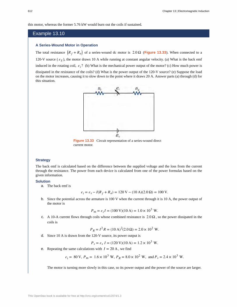
A Series-Wound Motor in Operation
The total resistance ⎛⎝R f + Ra
⎞⎠ of a series-wound dc motor is 2.0 Ω (Figure 13.33). When connected to a
120-V source ( εS ), the motor draws 10 A while running at constant angular velocity. (a) What is the back emf
induced in the rotating coil, εi? (b) What is the mechanical power output of the motor? (c) How much power is
dissipated in the resistance of the coils? (d) What is the power output of the 120-V source? (e) Suppose the loadon the motor increases, causing it to slow down to the point where it draws 20 A. Answer parts (a) through (d) forthis situation.
Figure 13.33 Circuit representation of a series-wound directcurrent motor.
Strategy
The back emf is calculated based on the difference between the supplied voltage and the loss from the currentthrough the resistance. The power from each device is calculated from one of the power formulas based on thegiven information.
Solutiona. The back emf is
εi = εs − I(R f + Ra) = 120 V − (10 A)(2.0 Ω) = 100 V.
b. Since the potential across the armature is 100 V when the current through it is 10 A, the power output ofthe motor is
Pm = εi I = (100 V)(10 A) = 1.0 × 10³ W.c. A 10-A current flows through coils whose combined resistance is 2.0 Ω , so the power dissipated in the
coils is
PR = I 2 R = (10 A)2(2.0 Ω) = 2.0 × 10² W.d. Since 10 A is drawn from the 120-V source, its power output is
Ps = εs I = (120 V)(10 A) = 1.2 × 10³ W.e. Repeating the same calculations with I = 20 A , we find
εi = 80 V, Pm = 1.6 × 10³ W, PR = 8.0 × 10² W, and Ps = 2.4 × 10³ W.
The motor is turning more slowly in this case, so its power output and the power of the source are larger.
612 Chapter 13 | Electromagnetic Induction
This OpenStax book is available for free at http://cnx.org/content/col12074/1.3

Significance
Notice that we have an energy balance in part (d): 1.2 × 10³ W = 1.0 × 10³ W + 2.0 × 10² W.
13.7 | Applications of Electromagnetic Induction
Learning Objectives
By the end of this section, you will be able to:
• Explain how computer hard drives and graphic tablets operate using magnetic induction
• Explain how hybrid/electric vehicles and transcranial magnetic stimulation use magneticinduction to their advantage
Modern society has numerous applications of Faraday’s law of induction, as we will explore in this chapter and others. Atthis juncture, let us mention several that involve recording information using magnetic fields.
Some computer hard drives apply the principle of magnetic induction. Recorded data are made on a coated, spinning disk.Historically, reading these data was made to work on the principle of induction. However, most input information today iscarried in digital rather than analog form—a series of 0s or 1s are written upon the spinning hard drive. Therefore, mosthard drive readout devices do not work on the principle of induction, but use a technique known as giant magnetoresistance.Giant magnetoresistance is the effect of a large change of electrical resistance induced by an applied magnetic field to thinfilms of alternating ferromagnetic and nonmagnetic layers. This is one of the first large successes of nanotechnology.
Graphics tablets, or tablet computers where a specially designed pen is used to draw digital images, also applies inductionprinciples. The tablets discussed here are labeled as passive tablets, since there are other designs that use either a battery-operated pen or optical signals to write with. The passive tablets are different than the touch tablets and phones many of ususe regularly, but may still be found when signing your signature at a cash register. Underneath the screen, shown in Figure13.34, are tiny wires running across the length and width of the screen. The pen has a tiny magnetic field coming from thetip. As the tip brushes across the screen, a changing magnetic field is felt in the wires which translates into an induced emfthat is converted into the line you just drew.
Chapter 13 | Electromagnetic Induction 613

Figure 13.34 A tablet with a specially designed pen to write with is another application ofmagnetic induction.
Another application of induction is the magnetic stripe on the back of your personal credit card as used at the grocery storeor the ATM machine. This works on the same principle as the audio or video tape, in which a playback head reads personalinformation from your card.
Check out this video (https://openstaxcollege.org/l/21flashmagind) to see how flashlights can usemagnetic induction. A magnet moves by your mechanical work through a wire. The induced current charges acapacitor that stores the charge that will light the lightbulb even while you are not doing this mechanical work.
Electric and hybrid vehicles also take advantage of electromagnetic induction. One limiting factor that inhibits widespreadacceptance of 100% electric vehicles is that the lifetime of the battery is not as long as the time you get to drive on a fulltank of gas. To increase the amount of charge in the battery during driving, the motor can act as a generator whenever thecar is braking, taking advantage of the back emf produced. This extra emf can be newly acquired stored energy in the car’sbattery, prolonging the life of the battery.
Another contemporary area of research in which electromagnetic induction is being successfully implemented istranscranial magnetic stimulation (TMS). A host of disorders, including depression and hallucinations, can be traced toirregular localized electrical activity in the brain. In transcranial magnetic stimulation, a rapidly varying and very localizedmagnetic field is placed close to certain sites identified in the brain. The usage of TMS as a diagnostic technique is wellestablished.
Check out this Youtube video (https://openstaxcollege.org/l/21randrelectro) to see how rock-and-rollinstruments like electric guitars use electromagnetic induction to get those strong beats.
614 Chapter 13 | Electromagnetic Induction
This OpenStax book is available for free at http://cnx.org/content/col12074/1.3

back emf
eddy current
electric generator
Faraday’s law
induced electric field
induced emf
Lenz’s law
magnetic damping
magnetic flux
motionally induced emf
peak emf
CHAPTER 13 REVIEW
KEY TERMSemf generated by a running motor, because it consists of a coil turning in a magnetic field; it opposes the
voltage powering the motor
current loop in a conductor caused by motional emf
device for converting mechanical work into electric energy; it induces an emf by rotating a coil in amagnetic field
induced emf is created in a closed loop due to a change in magnetic flux through the loop
created based on the changing magnetic flux with time
short-lived voltage generated by a conductor or coil moving in a magnetic field
direction of an induced emf opposes the change in magnetic flux that produced it; this is the negative sign inFaraday’s law
drag produced by eddy currents
measurement of the amount of magnetic field lines through a given area
voltage produced by the movement of a conducting wire in a magnetic field
maximum emf produced by a generator
KEY EQUATIONS
Magnetic flux Φm = ∫S
B→ · n̂dA
Faraday’s law ε = − N dΦmdt
Motionally induced emf ε = Blv
Motional emf around a circuit ε = ∮ E→ · d l→ = − dΦmdt
Emf produced by an electric generator ε = NBA ω sin(ωt)
SUMMARY
13.1 Faraday’s Law
• The magnetic flux through an enclosed area is defined as the amount of field lines cutting through a surface area Adefined by the unit area vector.
• The units for magnetic flux are webers, where 1 Wb = 1 T · m2.
• The induced emf in a closed loop due to a change in magnetic flux through the loop is known as Faraday’s law. Ifthere is no change in magnetic flux, no induced emf is created.
13.2 Lenz's Law
• We can use Lenz’s law to determine the directions of induced magnetic fields, currents, and emfs.
• The direction of an induced emf always opposes the change in magnetic flux that causes the emf, a result known asLenz’s law.
Chapter 13 | Electromagnetic Induction 615

13.3 Motional Emf
• The relationship between an induced emf ε in a wire moving at a constant speed v through a magnetic field B is
given by ε = Blv.
• An induced emf from Faraday’s law is created from a motional emf that opposes the change in flux.
13.4 Induced Electric Fields
• A changing magnetic flux induces an electric field.
• Both the changing magnetic flux and the induced electric field are related to the induced emf from Faraday’s law.
13.5 Eddy Currents
• Current loops induced in moving conductors are called eddy currents. They can create significant drag, calledmagnetic damping.
• Manipulation of eddy currents has resulted in applications such as metal detectors, braking in trains or rollercoasters, and induction cooktops.
13.6 Electric Generators and Back Emf
• An electric generator rotates a coil in a magnetic field, inducing an emf given as a function of time byε = NBAω sin(ωt) where A is the area of an N-turn coil rotated at a constant angular velocity ω in a uniform
magnetic field B→ .
• The peak emf of a generator is ε0 = NBAω .
• Any rotating coil produces an induced emf. In motors, this is called back emf because it opposes the emf input tothe motor.
13.7 Applications of Electromagnetic Induction
• Hard drives utilize magnetic induction to read/write information.
• Other applications of magnetic induction can be found in graphics tablets, electric and hybrid vehicles, and intranscranial magnetic stimulation.
CONCEPTUAL QUESTIONS
13.1 Faraday’s Law
1. A stationary coil is in a magnetic field that is changingwith time. Does the emf induced in the coil depend on theactual values of the magnetic field?
2. In Faraday’s experiments, what would be the advantageof using coils with many turns?
3. A copper ring and a wooden ring of the samedimensions are placed in magnetic fields so that there is thesame change in magnetic flux through them. Compare theinduced electric fields and currents in the rings.
4. Discuss the factors determining the induced emf in aclosed loop of wire.
5. (a) Does the induced emf in a circuit depend on the
resistance of the circuit? (b) Does the induced currentdepend on the resistance of the circuit?
6. How would changing the radius of loop D shown belowaffect its emf, assuming C and D are much closer togethercompared to their radii?
7. Can there be an induced emf in a circuit at an instantwhen the magnetic flux through the circuit is zero?
8. Does the induced emf always act to decrease the
616 Chapter 13 | Electromagnetic Induction
This OpenStax book is available for free at http://cnx.org/content/col12074/1.3

magnetic flux through a circuit?
9. How would you position a flat loop of wire in achanging magnetic field so that there is no induced emf inthe loop?
10. The normal to the plane of a single-turn conductingloop is directed at an angle θ to a spatially uniform
magnetic field B→ . It has a fixed area and orientation
relative to the magnetic field. Show that the emf induced inthe loop is given by ε = (dB/dt)(A cos θ), where A is the
area of the loop.
13.2 Lenz's Law
11. The circular conducting loops shown in theaccompanying figure are parallel, perpendicular to theplane of the page, and coaxial. (a) When the switch S isclosed, what is the direction of the current induced in D?(b) When the switch is opened, what is the direction of thecurrent induced in loop D?
12. The north pole of a magnet is moved toward a copperloop, as shown below. If you are looking at the loop fromabove the magnet, will you say the induced current iscirculating clockwise or counterclockwise?
13. The accompanying figure shows a conducting ringat various positions as it moves through a magnetic field.What is the sense of the induced emf for each of thosepositions?
14. Show that ε and dΦm /dt have the same units.
15. State the direction of the induced current for each caseshown below, observing from the side of the magnet.
13.3 Motional Emf
16. A bar magnet falls under the influence of gravity alongthe axis of a long copper tube. If air resistance is negligible,will there be a force to oppose the descent of the magnet?If so, will the magnet reach a terminal velocity?
17. Around the geographic North Pole (or magnetic SouthPole), Earth’s magnetic field is almost vertical. If anairplane is flying northward in this region, which side ofthe wing is positively charged and which is negativelycharged?
18. A wire loop moves translationally (no rotation) ina uniform magnetic field. Is there an emf induced in theloop?
Chapter 13 | Electromagnetic Induction 617

13.4 Induced Electric Fields
19. Is the work required to accelerate a rod from rest toa speed v in a magnetic field greater than the final kineticenergy of the rod? Why?
20. The copper sheet shown below is partially in amagnetic field. When it is pulled to the right, a resistingforce pulls it to the left. Explain. What happen if the sheetis pushed to the left?
13.5 Eddy Currents
21. A conducting sheet lies in a plane perpendicular to
a magnetic field B→ that is below the sheet. If B→
oscillates at a high frequency and the conductor is madeof a material of low resistivity, the region above the sheet
is effectively shielded from B→ . Explain why. Will the
conductor shield this region from static magnetic fields?
22. Electromagnetic braking can be achieved by applyinga strong magnetic field to a spinning metal disk attached toa shaft. (a) How can a magnetic field slow the spinning ofa disk? (b) Would the brakes work if the disk was made ofplastic instead of metal?
23. A coil is moved through a magnetic field as shownbelow. The field is uniform inside the rectangle and zerooutside. What is the direction of the induced current andwhat is the direction of the magnetic force on the coil ateach position shown?
PROBLEMS
13.1 Faraday’s Law
24. A 50-turn coil has a diameter of 15 cm. The coil isplaced in a spatially uniform magnetic field of magnitude0.50 T so that the face of the coil and the magnetic field areperpendicular. Find the magnitude of the emf induced in thecoil if the magnetic field is reduced to zero uniformly in (a)0.10 s, (b) 1.0 s, and (c) 60 s.
25. Repeat your calculations of the preceding problem’stime of 0.1 s with the plane of the coil making an angle of(a) 30°, (b) 60°, and (c) 90° with the magnetic field.
26. A square loop whose sides are 6.0-cm long is madewith copper wire of radius 1.0 mm. If a magnetic fieldperpendicular to the loop is changing at a rate of 5.0 mT/s,what is the current in the loop?
27. The magnetic field through a circular loop of radius10.0 cm varies with time as shown below. The field isperpendicular to the loop. Plot the magnitude of the inducedemf in the loop as a function of time.
28. The accompanying figure shows a single-turnrectangular coil that has a resistance of 2.0 Ω. The
magnetic field at all points inside the coil varies accordingto B = B0 e−αt, where B0 = 0.25 T and α = 200 Hz.What is the current induced in the coil at (a) t = 0.001 s ,
(b) 0.002 s, (c) 2.0 s?
618 Chapter 13 | Electromagnetic Induction
This OpenStax book is available for free at http://cnx.org/content/col12074/1.3

29. How would the answers to the preceding problemchange if the coil consisted of 20 closely spaced turns?
30. A long solenoid with n = 10 turns per centimeter has
a cross-sectional area of 5.0 cm2 and carries a current of
0.25 A. A coil with five turns encircles the solenoid. Whenthe current through the solenoid is turned off, it decreasesto zero in 0.050 s. What is the average emf induced in thecoil?
31. A rectangular wire loop with length a and width blies in the xy-plane, as shown below. Within the loop thereis a time-dependent magnetic field given by
B→ (t) = C⎛⎝(x cos ωt) i
^+ (y sin ωt) k̂⎞
⎠ , with B→ (t) in
tesla. Determine the emf induced in the loop as a functionof time.
32. The magnetic field perpendicular to a single wire loopof diameter 10.0 cm decreases from 0.50 T to zero. Thewire is made of copper and has a diameter of 2.0 mm andlength 1.0 cm. How much charge moves through the wirewhile the field is changing?
13.2 Lenz's Law
33. A single-turn circular loop of wire of radius 50 mmlies in a plane perpendicular to a spatially uniform magneticfield. During a 0.10-s time interval, the magnitude of thefield increases uniformly from 200 to 300 mT. (a)Determine the emf induced in the loop. (b) If the magneticfield is directed out of the page, what is the direction of thecurrent induced in the loop?
34. When a magnetic field is first turned on, the fluxthrough a 20-turn loop varies with time according to
Φm = 5.0t2 − 2.0t, where Φm is in milliwebers, t is in
seconds, and the loop is in the plane of the page with theunit normal pointing outward. (a) What is the emf inducedin the loop as a function of time? What is the direction ofthe induced current at (b) t = 0, (c) 0.10, (d) 1.0, and (e) 2.0s?
35. The magnetic flux through the loop shown in theaccompanying figure varies with time according to
Φm = 2.00e−3t sin(120πt), where Φm is in
milliwebers. What are the direction and magnitude of thecurrent through the 5.00-Ω resistor at (a) t = 0 ; (b)
t = 2.17 × 10⁻² s, and (c) t = 3.00 s?
36. Use Lenz’s law to determine the direction of inducedcurrent in each case.
13.3 Motional Emf
37. An automobile with a radio antenna 1.0 m long travelsat 100.0 km/h in a location where the Earth’s horizontal
magnetic field is 5.5 × 10⁻⁵ T. What is the maximum
possible emf induced in the antenna due to this motion?
38. The rectangular loop of N turns shown below moves
to the right with a constant velocity v→ while leaving
the poles of a large electromagnet. (a) Assuming that themagnetic field is uniform between the pole faces andnegligible elsewhere, determine the induced emf in theloop. (b) What is the source of work that produces this emf?
Chapter 13 | Electromagnetic Induction 619
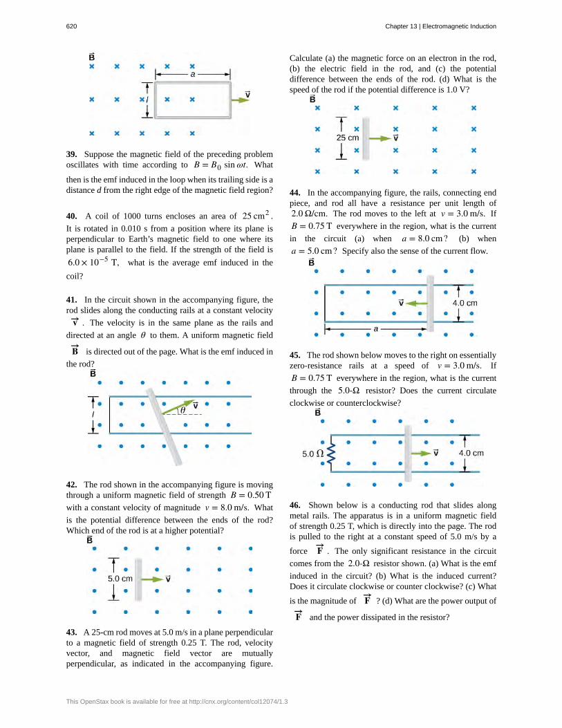
39. Suppose the magnetic field of the preceding problemoscillates with time according to B = B0 sin ωt. What
then is the emf induced in the loop when its trailing side is adistance d from the right edge of the magnetic field region?
40. A coil of 1000 turns encloses an area of 25 cm2 .
It is rotated in 0.010 s from a position where its plane isperpendicular to Earth’s magnetic field to one where itsplane is parallel to the field. If the strength of the field is
6.0 × 10⁻⁵ T, what is the average emf induced in the
coil?
41. In the circuit shown in the accompanying figure, therod slides along the conducting rails at a constant velocity
v→ . The velocity is in the same plane as the rails and
directed at an angle θ to them. A uniform magnetic field
B→ is directed out of the page. What is the emf induced in
the rod?
42. The rod shown in the accompanying figure is movingthrough a uniform magnetic field of strength B = 0.50 Twith a constant velocity of magnitude v = 8.0 m/s. What
is the potential difference between the ends of the rod?Which end of the rod is at a higher potential?
43. A 25-cm rod moves at 5.0 m/s in a plane perpendicularto a magnetic field of strength 0.25 T. The rod, velocityvector, and magnetic field vector are mutuallyperpendicular, as indicated in the accompanying figure.
Calculate (a) the magnetic force on an electron in the rod,(b) the electric field in the rod, and (c) the potentialdifference between the ends of the rod. (d) What is thespeed of the rod if the potential difference is 1.0 V?
44. In the accompanying figure, the rails, connecting endpiece, and rod all have a resistance per unit length of2.0 Ω/cm. The rod moves to the left at v = 3.0 m/s. If
B = 0.75 T everywhere in the region, what is the current
in the circuit (a) when a = 8.0 cm? (b) when
a = 5.0 cm? Specify also the sense of the current flow.
45. The rod shown below moves to the right on essentiallyzero-resistance rails at a speed of v = 3.0 m/s. If
B = 0.75 T everywhere in the region, what is the current
through the 5.0-Ω resistor? Does the current circulate
clockwise or counterclockwise?
46. Shown below is a conducting rod that slides alongmetal rails. The apparatus is in a uniform magnetic fieldof strength 0.25 T, which is directly into the page. The rodis pulled to the right at a constant speed of 5.0 m/s by a
force F→ . The only significant resistance in the circuit
comes from the 2.0-Ω resistor shown. (a) What is the emf
induced in the circuit? (b) What is the induced current?Does it circulate clockwise or counter clockwise? (c) What
is the magnitude of F→ ? (d) What are the power output of
F→ and the power dissipated in the resistor?
620 Chapter 13 | Electromagnetic Induction
This OpenStax book is available for free at http://cnx.org/content/col12074/1.3

13.4 Induced Electric Fields
47. Calculate the induced electric field in a 50-turn coilwith a diameter of 15 cm that is placed in a spatiallyuniform magnetic field of magnitude 0.50 T so that theface of the coil and the magnetic field are perpendicular.This magnetic field is reduced to zero in 0.10 seconds.Assume that the magnetic field is cylindrically symmetricwith respect to the central axis of the coil.
48. The magnetic field through a circular loop of radius10.0 cm varies with time as shown in the accompanyingfigure. The field is perpendicular to the loop. Assumingcylindrical symmetry with respect to the central axis of theloop, plot the induced electric field in the loop as a functionof time.
49. The current I through a long solenoid with n turns permeter and radius R is changing with time as given by dI/dt.Calculate the induced electric field as a function of distancer from the central axis of the solenoid.
50. Calculate the electric field induced both inside andoutside the solenoid of the preceding problem ifI = I0 sin ωt.
51. Over a region of radius R, there is a spatially uniform
magnetic field B→ . (See below.) At t = 0 , B = 1.0 T,after which it decreases at a constant rate to zero in 30 s.(a) What is the electric field in the regions where r ≤ Rand r ≥ R during that 30-s interval? (b) Assume that
R = 10.0 cm . How much work is done by the electric
field on a proton that is carried once clock wise arounda circular path of radius 5.0 cm? (c) How much workis done by the electric field on a proton that is carriedonce counterclockwise around a circular path of any radiusr ≥ R ? (d) At the instant when B = 0.50 T , a proton
enters the magnetic field at A, moving a velocity v→⎛⎝v = 5.0 × 10⁶ m/s⎞
⎠ as shown. What are the electric and
magnetic forces on the proton at that instant?
52. The magnetic field at all points within the cylindricalregion whose cross-section is indicated in theaccompanying figure starts at 1.0 T and decreasesuniformly to zero in 20 s. What is the electric field (bothmagnitude and direction) as a function of r, the distancefrom the geometric center of the region?
53. The current in a long solenoid of radius 3 cm is variedwith time at a rate of 2 A/s. A circular loop of wire of radius5 cm and resistance 2 Ω surrounds the solenoid. Find the
electrical current induced in the loop.
54. The current in a long solenoid of radius 3 cm and 20turns/cm is varied with time at a rate of 2 A/s. Find theelectric field at a distance of 4 cm from the center of thesolenoid.
13.6 Electric Generators and Back Emf
55. Design a current loop that, when rotated in a uniformmagnetic field of strength 0.10 T, will produce an emfε = ε0 sin ωt, where ε0 = 110 V and ω = 120π rad/s.
Chapter 13 | Electromagnetic Induction 621

56. A flat, square coil of 20 turns that has sides of length15.0 cm is rotating in a magnetic field of strength 0.050 T.If the maximum emf produced in the coil is 30.0 mV, whatis the angular velocity of the coil?
57. A 50-turn rectangular coil with dimensions0.15 m × 0.40 m rotates in a uniform magnetic field of
magnitude 0.75 T at 3600 rev/min. (a) Determine the emfinduced in the coil as a function of time. (b) If the coil isconnected to a 1000-Ω resistor, what is the power as a
function of time required to keep the coil turning at 3600rpm? (c) Answer part (b) if the coil is connected to a 2000-Ω resistor.
58. The square armature coil of an alternating currentgenerator has 200 turns and is 20.0 cm on side. When itrotates at 3600 rpm, its peak output voltage is 120 V. (a)What is the frequency of the output voltage? (b) What is thestrength of the magnetic field in which the coil is turning?
59. A flip coil is a relatively simple device used tomeasure a magnetic field. It consists of a circular coil of Nturns wound with fine conducting wire. The coil is attachedto a ballistic galvanometer, a device that measures the totalcharge that passes through it. The coil is placed in a
magnetic field B→ such that its face is perpendicular to
the field. It is then flipped through 180°, and the total
charge Q that flows through the galvanometer is measured.(a) If the total resistance of the coil and galvanometer is R,what is the relationship between B and Q? Because the coil
is very small, you can assume that B→ is uniform over
it. (b) How can you determine whether or not the magneticfield is perpendicular to the face of the coil?
60. The flip coil of the preceding problem has a radius of3.0 cm and is wound with 40 turns of copper wire. The totalresistance of the coil and ballistic galvanometer is 0.20 Ω.When the coil is flipped through 180° in a magnetic field
B→ , a change of 0.090 C flows through the ballistic
galvanometer. (a) Assuming that B→ and the face of the
coil are initially perpendicular, what is the magnetic field?(b) If the coil is flipped through 90°, what is the reading
of the galvanometer?
61. A 120-V, series-wound motor has a field resistanceof 80 Ω and an armature resistance of 10 Ω . When it is
operating at full speed, a back emf of 75 V is generated. (a)What is the initial current drawn by the motor? When themotor is operating at full speed, where are (b) the currentdrawn by the motor, (c) the power output of the source, (d)the power output of the motor, and (e) the power dissipatedin the two resistances?
62. A small series-wound dc motor is operated from a12-V car battery. Under a normal load, the motor draws4.0 A, and when the armature is clamped so that it cannotturn, the motor draws 24 A. What is the back emf when themotor is operating normally?
ADDITIONAL PROBLEMS
63. Shown in the following figure is a long, straight wireand a single-turn rectangular loop, both of which lie in theplane of the page. The wire is parallel to the long sides ofthe loop and is 0.50 m away from the closer side. At aninstant when the emf induced in the loop is 2.0 V, what isthe time rate of change of the current in the wire?
64. A metal bar of mass 500 g slides outward at a constantspeed of 1.5 cm/s over two parallel rails separated by adistance of 30 cm which are part of a U-shaped conductor.There is a uniform magnetic field of magnitude 2 Tpointing out of the page over the entire area. The railingsand metal bar have an equivalent resistance of 150 Ω.
(a) Determine the induced current, both magnitude anddirection. (b) Find the direction of the induced current ifthe magnetic field is pointing into the page. (c) Find thedirection of the induced current if the magnetic field ispointed into the page and the bar moves inwards.
65. A current is induced in a circular loop of radius 1.5 cmbetween two poles of a horseshoe electromagnet when thecurrent in the electromagnet is varied. The magnetic fieldin the area of the loop is perpendicular to the area and has auniform magnitude. If the rate of change of magnetic fieldis 10 T/s, find the magnitude and direction of the inducedcurrent if resistance of the loop is 25 Ω .
66. A metal bar of length 25 cm is placed perpendicularto a uniform magnetic field of strength 3 T. (a) Determinethe induced emf between the ends of the rod when it isnot moving. (b) Determine the emf when the rod is movingperpendicular to its length and magnetic field with a speed
622 Chapter 13 | Electromagnetic Induction
This OpenStax book is available for free at http://cnx.org/content/col12074/1.3

of 50 cm/s.
67. A coil with 50 turns and area 10 cm2 is oriented with
its plane perpendicular to a 0.75-T magnetic field. If thecoil is flipped over (rotated through 180° ) in 0.20 s, what
is the average emf induced in it?
68. A 2-turn planer loop of flexible wire is placed insidea long solenoid of n turns per meter that carries a constantcurrent I0 . The area A of the loop is changed by pulling
on its sides while ensuring that the plane of the loop alwaysremains perpendicular to the axis of the solenoid. If
n = 500 turns per meter, I0 = 20 A, and A = 20 cm2,what is the emf induced in the loop when dA/dt = 100?
69. The conducting rod shown in the accompanying figuremoves along parallel metal rails that are 25-cm apart. Thesystem is in a uniform magnetic field of strength 0.75T, which is directed into the page. The resistances of therod and the rails are negligible, but the section PQ has aresistance of 0.25 Ω . (a) What is the emf (including its
sense) induced in the rod when it is moving to the right witha speed of 5.0 m/s? (b) What force is required to keep therod moving at this speed? (c) What is the rate at which workis done by this force? (d) What is the power dissipated inthe resistor?
70. A circular loop of wire of radius 10 cm is mountedon a vertical shaft and rotated at a frequency of 5 cyclesper second in a region of uniform magnetic field of 2Gauss perpendicular to the axis of rotation. (a) Find anexpression for the time-dependent flux through the ring. (b)Determine the time-dependent current through the ring if ithas a resistance of 10 Ω.
71. The magnetic field between the poles of a horseshoeelectromagnet is uniform and has a cylindrical symmetryabout an axis from the middle of the South Pole to themiddle of the North Pole. The magnitude of the magneticfield changes as a rate of dB/dt due to the changing currentthrough the electromagnet. Determine the electric field at adistance r from the center.
72. A long solenoid of radius a with n turns per unit lengthis carrying a time-dependent current I(t) = I0 sin(ωt) ,
where I0 and ω are constants. The solenoid is surrounded
by a wire of resistance R that has two circular loops ofradius b with b > a (see the following figure). Find the
magnitude and direction of current induced in the outerloops at time t = 0 .
73. A 120-V, series-wound dc motor draws 0.50 A fromits power source when operating at full speed, and it draws2.0 A when it starts. The resistance of the armature coilsis 10 Ω . (a) What is the resistance of the field coils? (b)
What is the back emf of the motor when it is running atfull speed? (c) The motor operates at a different speed anddraws 1.0 A from the source. What is the back emf in thiscase?
74. The armature and field coils of a series-wound motorhave a total resistance of 3.0 Ω . When connected to a
120-V source and running at normal speed, the motor draws4.0 A. (a) How large is the back emf? (b) What current willthe motor draw just after it is turned on? Can you suggest away to avoid this large initial current?
CHALLENGE PROBLEMS
75. A copper wire of length L is fashioned into a circular coil with N turns. When the magnetic field through the coil
Chapter 13 | Electromagnetic Induction 623

changes with time, for what value of N is the induced emf amaximum?
76. A 0.50-kg copper sheet drops through a uniformhorizontal magnetic field of 1.5 T, and it reaches a terminalvelocity of 2.0 m/s. (a) What is the net magnetic force onthe sheet after it reaches terminal velocity? (b) Describethe mechanism responsible for this force. (c) How muchpower is dissipated as Joule heating while the sheet movesat terminal velocity?
77. A circular copper disk of radius 7.5 cm rotates at 2400rpm around the axis through its center and perpendicular
to its face. The disk is in a uniform magnetic field B→
of strength 1.2 T that is directed along the axis. What isthe potential difference between the rim and the axis of thedisk?
78. A short rod of length a moves with its velocity v→
parallel to an infinite wire carrying a current I (see below).If the end of the rod nearer the wire is a distance b from thewire, what is the emf induced in the rod?
79. A rectangular circuit containing a resistance R is
pulled at a constant velocity v→ away from a long,
straight wire carrying a current I0 (see below). Derive an
equation that gives the current induced in the circuit asa function of the distance x between the near side of thecircuit and the wire.
80. Two infinite solenoids cross the plane of the circuit
as shown below. The radii of the solenoids are 0.10 and0.20 m, respectively, and the current in each solenoid ischanging such that dB/dt = 50.0 T/s. What are the
currents in the resistors of the circuit?
81. An eight-turn coil is tightly wrapped around theoutside of the long solenoid as shown below. The radius ofthe solenoid is 2.0 cm and it has 10 turns per centimeter.The current through the solenoid increases according toI = I0(1 − e−αt), where I0 = 4.0 A and
α = 2.0 × 10⁻² s−1. What is the emf induced in the coil
when (a) t = 0 , (b) t = 1.0 × 10² s, and (c) t → ∞?
82. Shown below is a long rectangular loop of width w,
624 Chapter 13 | Electromagnetic Induction
This OpenStax book is available for free at http://cnx.org/content/col12074/1.3

length l, mass m, and resistance R. The loop starts from rest
at the edge of a uniform magnetic field B→ and is pushed
into the field by a constant force F→ . Calculate the speed
of the loop as a function of time.
83. A square bar of mass m and resistance R is slidingwithout friction down very long, parallel conducting railsof negligible resistance (see below). The two rails are adistance l apart and are connected to each other at thebottom of the incline by a zero-resistance wire. The railsare inclined at an angle θ , and there is a uniform vertical
magnetic field B→ throughout the region. (a) Show that
the bar acquires a terminal velocity given by
v = mgR sin θB2 l2 cos2 θ
. (b) Calculate the work per unit time
done by the force of gravity. (c) Compare this with thepower dissipated in the Joule heating of the bar. (d) What
would happen if B→ were reversed?
84. The accompanying figure shows a metal disk of innerradius r1 and other radius r2 rotating at an angular
velocity ω→ while in a uniform magnetic field directed
parallel to the rotational axis. The brush leads of avoltmeter are connected to the dark’s inner and outersurfaces as shown. What is the reading of the voltmeter?
85. A long solenoid with 10 turns per centimeter is placedinside a copper ring such that both objects have the samecentral axis. The radius of the ring is 10.0 cm, and theradius of the solenoid is 5.0 cm. (a) What is the emf inducedin the ring when the current I through the solenoid is 5.0A and changing at a rate of 100 A/s? (b) What is theemf induced in the ring when I = 2.0 A and
dI/dt = 100 A/s? (c) What is the electric field inside the
ring for these two cases? (d) Suppose the ring is moved sothat its central axis and the central axis of the solenoid arestill parallel but no longer coincide. (You should assumethat the solenoid is still inside the ring.) Now what is theemf induced in the ring? (e) Can you calculate the electricfield in the ring as you did in part (c)?
86. The current in the long, straight wire shown in theaccompanying figure is given by I = I0 sin ωt, where
I0 = 15 A and ω = 120π rad/s. What is the current
induced in the rectangular loop at (a) t = 0 and (b)
t = 2.1 × 10⁻³ s? The resistance of the loop is 2.0 Ω.
87. A 500-turn coil with a 0.250-m2 area is spun in
Earth’s 5.00 × 10⁻⁵ T magnetic field, producing a
12.0-kV maximum emf. (a) At what angular velocity mustthe coil be spun? (b) What is unreasonable about thisresult? (c) Which assumption or premise is responsible?
Chapter 13 | Electromagnetic Induction 625

88. A circular loop of wire of radius 10 cm is mountedon a vertical shaft and rotated at a frequency of 5 cyclesper second in a region of uniform magnetic field of
2 × 10⁻⁴ T perpendicular to the axis of rotation. (a) Find
an expression for the time-dependent flux through the ring(b) Determine the time-dependent current through the ringif it has a resistance of 10 Ω .
89. A long solenoid of radius a with n turns per unit
length is carrying a time-dependent currentI(t) = I0 sin ωt where I0 and ω are constants. The
solenoid is surrounded by a wire of resistance R that hastwo circular loops of radius b with b > a . Find the
magnitude and direction of current induced in the outerloops at time t = 0 .
90. A rectangular copper loop of mass 100 g andresistance 0.2 Ω is in a region of uniform magnetic field
that is perpendicular to the area enclosed by the ring andhorizontal to Earth’s surface (see below). The loop is let gofrom rest when it is at the edge of the nonzero magneticfield region. (a) Find an expression for the speed whenthe loop just exits the region of uniform magnetic field.(b) If it was let go at t = 0 , what is the time when it
exits the region of magnetic field for the following values:
a = 25 cm, b = 50 cm, B = 3 T , g = 9.8 m/s2 ? Assume
that the magnetic field of the induced current is negligiblecompared to 3 T.
91. A metal bar of mass m slides without friction over tworails a distance D apart in the region that has a uniformmagnetic field of magnitude B0 and direction
perpendicular to the rails (see below). The two rails areconnected at one end to a resistor whose resistance is muchlarger than the resistance of the rails and the bar. The baris given an initial speed of v0 . It is found to slow down.
How far does the bar go before coming to rest? Assumethat the magnetic field of the induced current is negligiblecompared to B0 .
92. A time-dependent uniform magnetic field ofmagnitude B(t) is confined in a cylindrical region of radiusR. A conducting rod of length 2D is placed in the region,as shown below. Show that the emf between the ends of
the rod is given by dBdt D R2 − D2 . (Hint: To find the emf
between the ends, we need to integrate the electric fieldfrom one end to the other. To find the electric field, useFaraday’s law as “Ampère’s law for E.”)
626 Chapter 13 | Electromagnetic Induction
This OpenStax book is available for free at http://cnx.org/content/col12074/1.3
Related Documents