CHAPTER 13-14 CHAPTER 13-14 Reflection and Refraction of Reflection and Refraction of Light Light A is A “Something cannot be itself and something else at the same time.” Aristotle Light exhibits wave-like properties when studied under certain conditions. Light exhibits particle-like properties when studied under certain conditions. Light does not exhibit wave-like and particle-like properties simultaneously.

CHAPTER 13-14 Reflection and Refraction of Light A is A “Something cannot be itself and something else at the same time.” Aristotle Light exhibits wave-like.
Dec 18, 2015
Welcome message from author
This document is posted to help you gain knowledge. Please leave a comment to let me know what you think about it! Share it to your friends and learn new things together.
Transcript
CHAPTER 13-14CHAPTER 13-14Reflection and Refraction of LightReflection and Refraction of Light
A is A
“Something cannot be itself and something else at the same time.”
Aristotle
Light exhibits wave-like properties when studied under certain conditions.
Light exhibits particle-like properties when studied under certain conditions.
Light does not exhibit wave-like and particle-like properties simultaneously.
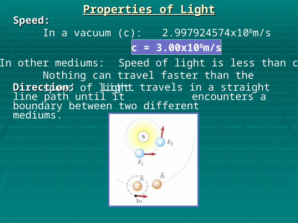
Properties of LightProperties of LightSpeed:Speed:
In a vacuum (c): 2.997924574x10⁸m/s
c = 3.00x10⁸m/s
In other mediums: Speed of light is less than c.Nothing can travel faster than the speed of light.
Direction:Direction: Light travels in a straight line path until it encounters a boundary between two different mediums.

Ray Model of LightRay Model of LightReflection:Reflection: Light rays reflect (bounce) off the surface of a
new medium that it encounters in a very predictable fashion.
The “Normal” is a line perpendicular to the surface of the second medium.
1 = 1’
Angle of Incidence (1) = Angle of Reflection (1’)Angles are measured from the Normal.
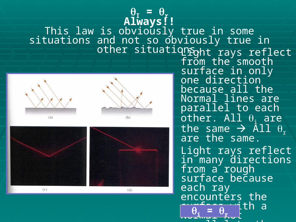
I = rAlways!!
This law is obviously true in some situations and not so obviously true in other situations.
Light rays reflect from the smooth surface in only one direction because all the Normal lines are parallel to each other. All i are the same All r are the same.Light rays reflect in many directions from a rough surface because each ray encounters the surface with a Normal not parallel to the other Normals.However, for each ray:
i = r

Flat (Plane) MirrorsFlat (Plane) Mirrors
Terms:Terms:Plane Mirror:Plane Mirror: Flat MirrorObject:Object: Physical thing placed in front of the mirrorObject Distance (dObject Distance (doo):): Distance of object from the front of the
mirrorImage:Image: The form of the object takes “in the mirror”Image Distance (dImage Distance (dii):): Distance of image from the front of the mirrorVirtual Image:Virtual Image: Located behind mirror. Rays appear to come
from it.Real Image:Real Image: Located in front of mirror. Rays converge to
form real images.

Flat Mirror (con’t)Flat Mirror (con’t)
Image:Image: Real or Virtual?Upright or Inverted?Magnification?
VirtualUpright
None (M=1)
Ray Diagrams:Ray Diagrams:Follow the Law of Reflection.Follow Snell’s Law (with lenses).Rays can be traced forward or backward.
Image Distance (di) and Object Distance (do)? Same

Spherical MirrorsSpherical Mirrors
Concave:Concave:
Principle Axis:Principle Axis: Line formed by point C and F. It runs to the center of the mirror and is perpendicular to the surface at the mirror’s center.
Center of Curvature (C):Center of Curvature (C): A point equidistant from all points on the mirrors surface. Distance from C to mirror equals “radius of curvature” of the sphere (from which the mirror is formed)
Focal Point (F):Focal Point (F): A point where all rays parallel to the Principle Axis converge after striking the mirror. (F=.5C)
NOTE: Relatively flat or small spherical mirrors are an approximation of a parabolic mirror.
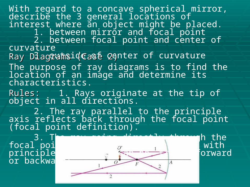
With regard to a concave spherical mirror, describe the 3 general locations of interest where an object might be placed.
1. between mirror and focal point2. between focal point and center of curvature3. outside of center of curvature
Ray Diagrams (Case 2)Ray Diagrams (Case 2)The purpose of ray diagrams is to find the location of an image and determine its characteristics.Rules:Rules:1. Rays originate at the tip of object in all directions.
2. The ray parallel to the principle axis reflects back through the focal point (focal point definition).
3. The ray going directly through the focal point reflects back parallel with principle axis (rays can be traced forward or backward).

Ray Diagram (Case 1)Ray Diagram (Case 1)
Notes:Notes:1. Three rays of interest can be drawn.2. Two rays determine a point. Three rays rarely come to a point even when they should.3. Use only two rays to find the tip of the image (Use Rays 1 and 2.)
The rays diverge in front of the mirror, but converge behind the mirror.ResultResultVirtual ImageUprightMagnified
Read the book and draw the 3rd case yourself.

Convex MirrorsConvex Mirrors
Rays of Interest:
1. Ray parallel to Principle Axis
2. Ray reflected perpendicularly off the surface (appear to come from center of curvature).
“Objects in mirror are closer than they appear.”

Mirror Equation (for Concave and Convex Mirrors)Mirror Equation (for Concave and Convex Mirrors)
1do
1f
1di
+ = f = ½ c
hi
ho
di
do
-M = =
do = + ALWAYS
di = + if image is in front of mirror (real image)
di = - if image is behind the mirror (virtual image)
f and c = + if they are in front of mirror (concave)
f and c = - if they are behind the mirror (convex)
M = + if upright

Ray Model of LightRay Model of Light
Refraction:Refraction: The tendency for light ray to bend when traveling from one medium into another medium. Examples:Examples: Rays traveling from:
air to waterair to glasswater to glass
Law of Reflection 1 = 1’v1 = speed of light in air (still approximately 3.0x10⁸m/s)v2 = speed of light in glass
v1 v2
1 = Incident Angle1’ = Reflected Angle2 = Angle of Refraction
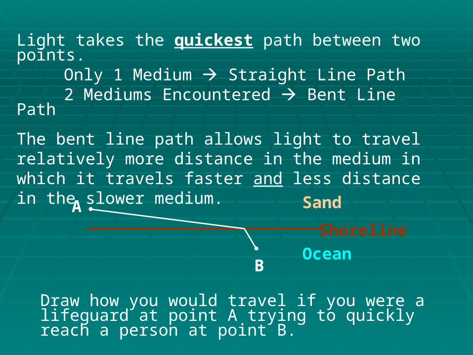
Light takes the quickest path between two points.Only 1 Medium Straight Line Path2 Mediums Encountered Bent Line Path
The bent line path allows light to travel relatively more distance in the medium in which it travels faster and less distance in the slower medium.
Draw how you would travel if you were a lifeguard at point A trying to quickly reach a person at point B.
Sand
Shoreline
Ocean
A
B

Light bends toward the Normal when passing from fast medium to a slow medium…just like the lifeguard.Light bends away from the Normal when passing from a slow to a fast medium…just like you in the ocean if you noticed someone stealing from your possessions on shore.
Your possessions
You
Normal
1
2

Law of RefractionLaw of Refraction
Index of Refraction (n)Index of Refraction (n) =speed of light in vacuumspeed of light in medium
n = cv
Index of Refraction is another physical property of a substance (medium)
n 1 because c v Always!However nair 1.00 (to 3 sig.figs.)
f1 = f2
Waves don’t “pile up” at the boundary.
v1 v2
1 2
The wavelength changes at the boundary.
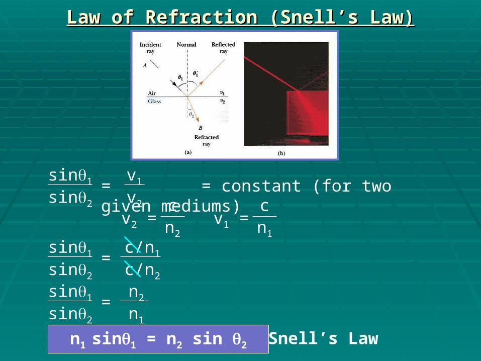
Law of Refraction (Snell’s Law)Law of Refraction (Snell’s Law)
sin1
sin2
v1
v2
= = constant (for two given mediums)
sin1
sin2
c/n1
c/n2
=
v2 = cn2
v1 = cn1
sin1
sin2
n2
n1
=
n1 sin1 = n2 sin 2 Snell’s Law

ExampleExample (Snell’s Law)
Find the angle (relative to the Normal) of the ray in the water.
Strategy:Strategy:Draw the Normal and measure 1 relative to the normal.Look up n1 and n2
n1 = 1.00 (air)n2 = 1.33 (water)Plug into Snell’s Law and Solve for 2
1.00 sin60 = 1.33 sin2
sin2 = .651 2 = sin-1(.651)2 = 41
1=60air
water
30
41
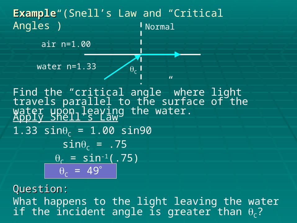
ExampleExample (Snell’s Law and “Critical Angles”)
Find the “critical angle” where light travels parallel to the surface of the water upon leaving the water.
Apply Snell’s Law1.33 sinC = 1.00 sin90 sinC = .75
C = sin-1(.75)C = 49
Question:Question:What happens to the light leaving the water if the incident angle is greater than C?
air n=1.00
water n=1.33
Normal
C

Total Internal ReflectionTotal Internal Reflection
Apply Snell’s Law1.33 sin60 = 1.00 sin2
sin2 = 1.15 2 = sin-1(1.15)
ERRORThe red ray is reflected internally as if the air/water surface acted like a mirror.The law of reflection is followed: 1 = 2
Where will the red ray travel? 60
air n=1.00
water n=1.33
C=49
=60
Normal

Fiber OpticsFiber Optics(Total Internal Reflection Application)(Total Internal Reflection Application)
Core:Core: Transparent material about the diameter of a piece of spaghetti.Light travels through the core.High or Low value for ncore?? High
Cladding:Cladding: Encases the core.Light is not supposed to travel through cladding.High or Low value for ncladding??
Low
Jacket:Jacket: Protective Coating End View
Jacket Cladding
Core

LensesLenses
Flat Lens is really a contradiction in terms.
Lenses are not flat!
“Thin” implies no “offset” from the original path.
Flat “Lens”Flat “Lens” Flat Thin “Lens”Flat Thin “Lens”

Converging LensesConverging Lenses
Lens FactorsMore Curvature
Larger Index of RefractionImmerse glass (n=1.5)lens in water (n=1.33)
Affect on Focal LengthShortens focal lengthShortens focal length
Lengthens focal length
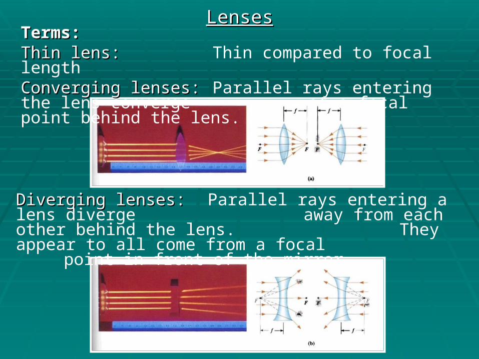
LensesLensesTerms:Terms:Thin lens:Thin lens: Thin compared to focal lengthConverging lenses:Converging lenses:Parallel rays entering the lens converge
at a focal point behind the lens.
Diverging lenses:Diverging lenses: Parallel rays entering a lens diverge away from each other behind the lens. They appear to all come from a focal point in front of the mirror.

Converging LensesConverging LensesRay DiagramsRay DiagramsPurpose:Purpose: Determine the location and characteristics of an image formed by a lens.Rules: 1. Rays parallel to the principle axis strike
the lens and bend towards the focal point behind the lens. (Definition of focal point)2. Rays passing through the focal point in front of the lens exit from the lens parallel to the principle axis. 3. Rays going through the center of the lens (at any angle) continue straight through the “thin” lens.
ExampleExample (Objects outside focal point)
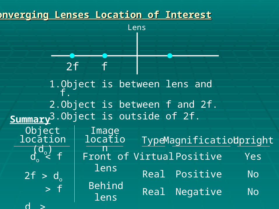
Converging Lenses Location of InterestConverging Lenses Location of Interest
1. Object is between lens and f.2. Object is between f and 2f.3. Object is outside of 2f.
Lens
2f f
Summary Object
location (do)Image
location Type Magnification Upright
do f
2f do f
do 2f
Front of lens
Behind lens
Behind lens
Virtual
Real
Real
Positive
Positive
Negative
Yes
No
No

Diverging LensesDiverging LensesRay Diagram Rules
1. Rays parallel to principle axis diverge through the lens and appear to originate at focal point in front of lens.2. Rays striking center of lens pass through lens without bending.3. Ray directed towards focal point behind the lens emerges from lens parallel to principle axis.

Lens EquationLens Equation
1do
1f
1di
+ =
hi
ho
di
do
-M = =
Exactly the same as with mirrors
Converging LensConverging Lens (Sign Convention) f = positivedo = positive if object in front of lens (real object)di = positive if image is in back of lens (real image)
ho = positive if object is uprighthi = positive if image is upright
Diverging LensDiverging Lens f = negativedo = positivedi = positive if image is in back of the lens (not typical)
Related Documents