Chapter 13-1 I/O Systems Chapter 13-1 I/O Systems

Chapter 13-1 I/O Systems. 13.2 Silberschatz, Galvin and Gagne ©2005 Operating System Concepts Chapter 13-1: I/O Systems Chapter 13-1 I/O Hardware Chapter.
Jan 15, 2016
Welcome message from author
This document is posted to help you gain knowledge. Please leave a comment to let me know what you think about it! Share it to your friends and learn new things together.
Transcript

Chapter 13-1 I/O SystemsChapter 13-1 I/O Systems

13.2 Silberschatz, Galvin and Gagne ©2005Operating System Concepts
Chapter 13-1: I/O SystemsChapter 13-1: I/O Systems
Chapter 13-1
I/O Hardware
Chapter 13-2
Application I/O Interface
Kernel I/O Subsystem
Transforming I/O Requests to Hardware Operations
Streams
Performance

13.3 Silberschatz, Galvin and Gagne ©2005Operating System Concepts
I/O SystemsI/O Systems
One of the more difficult chapters.
This chapter pulls together many things we’ve had, but in significantly more detail.
It is divided into some key sections:
An overview
I/O Hardware
Application I/O Interface
Kernel I/O System
Transforming I/O Requests to Hardware Operations
Streams
Performance
These will keep us busy. I plan to cover almost all of these sections and will supplement from other sources as I feel the need arises.

13.4 Silberschatz, Galvin and Gagne ©2005Operating System Concepts
I.I. IntroductionIntroduction Important to realize just how much of a constraint I/O operations place on a ‘computing
system.’ Yet I/O is, of course, essential, as we know that the I/O responsibilities include the
management and control of I/O operations and devices in an overall computing system where overall performance and efficiency are king.
The reality is that I/O devices differ markedly in capability, design, interfacing, and technologies along with the software and hardware that control these.
Authors approach I/O operations in the context of an I/O Subsystem – part of the kernel, but treated separately from the rest of the kernel.
I/O Subsystem is very complicated. ever-emerging new technologies in the form of specialized I/O devices Gives rise for significant standardization of interfacing and operations.
Have basic hardware interfacing elements: ports, buses, and I/O device controllers But great variability in how all these each define different ways to accommodate I/O Hardware must facilitate data transfer with an operating system that craves
performance and is software! So, how does the complexity of input / output actually get accommodated such that
high performance is maintained in accommodating the slowest, yet perhaps the most essential activity in a computing system: input/output.
We will look at all this in detail…
13.5 Silberschatz, Galvin and Gagne ©2005Operating System Concepts
2.2. I/O HardwareI/O Hardware
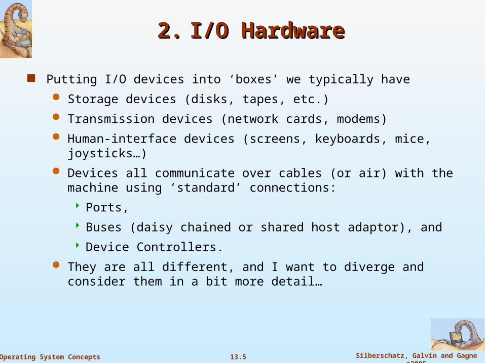
Putting I/O devices into ‘boxes’ we typically have
Storage devices (disks, tapes, etc.)
Transmission devices (network cards, modems)
Human-interface devices (screens, keyboards, mice, joysticks…)
Devices all communicate over cables (or air) with the machine using ‘standard’ connections:
Ports,
Buses (daisy chained or shared host adaptor), and
Device Controllers.
They are all different, and I want to diverge and consider them in a bit more detail…
13.6 Silberschatz, Galvin and Gagne ©2005Operating System Concepts
PortsPorts The CPU and its supporting circuitry provide Memory-mapped I/O, which involves a range of memory addresses simply
set aside and are mapped to device registers. Reads and writes to these memory addresses cause the data to be transferred to and from the device registers. A computer using memory-mapped I/O accesses hardware by reading and writing to specific memory locations using the
same assembler language instructions that the computer would normally use to access memory . So to accommodate the I/O devices, areas of CPU’s addressable space must be reserved for I/O (even temporarily) rather
than memory. We will return later with more on memory-mapped I/O
But the thinking of memory-mapped I/O can be applied to other devices such as the serial and parallel ports used to connect modems and printers to a computer.
Here, the CPU transfers data through these devices by reading and writing a few device registers called an I/O port. Port-mapped I/O usually requires the use of special instructions which are specifically designed to perform I/O operations,
such as the IN and OUT instructions found on Intel microprocessors. Here, I/O devices have a separate address space from general memory – either accomplished by an extra I/O pin on the
CPU’s physical interface or an entire bus dedicated to I/O
I/O ports are simply a few registers supporting data transfer from I/O devices and main memory. Very specific I/O instructions are executed to allow this data transfer to take place between these registers and main memory. So, simply consider a port as a set of hardware addresses whose contents are accessed via specific low-level instructions
(ahead).
If we access hardware through ports, we are dealing with the hardware directly. Mistakes may be disastrous, however, because there is no validation whether your input is correct or not – in general.
I/O ports only accept numbers (byte – 8 bits; or word (16 or 32 bits) This input depends on the hardware you want to deal with.
More interest: A computer using memory-mapped I/O accesses hardware by reading and writing to specific memory locations – using the same assembler language instructions that the computer would normally use to access memory.
(Access: not every port has both read and write access. Some have read only; some only write access. Interestingly, there may be a port register, which you may view as an array of data inside the hardware)

13.7 Silberschatz, Galvin and Gagne ©2005Operating System Concepts
Port Picture – older devicePort Picture – older device
This picture shows an internal view of some of the I/O ports on the right and a covered view on the left.
On the back of computers are several I/O ports.
Above, on the very top are two PS/2 ports, normally used for mouse and keyboard connections.
Below those are two USB, (or Universal Serial Bus), ports.
Below those are two serial ports beside a long parallel port that is often used to connect to a printer.
On the bottom right is a game port for joysticks or other game controllers.
On the bottom left is a microphone hook up, a speaker hook up, and an additional hook up for another sound input device like a musical keyboard.
13.8 Silberschatz, Galvin and Gagne ©2005Operating System Concepts
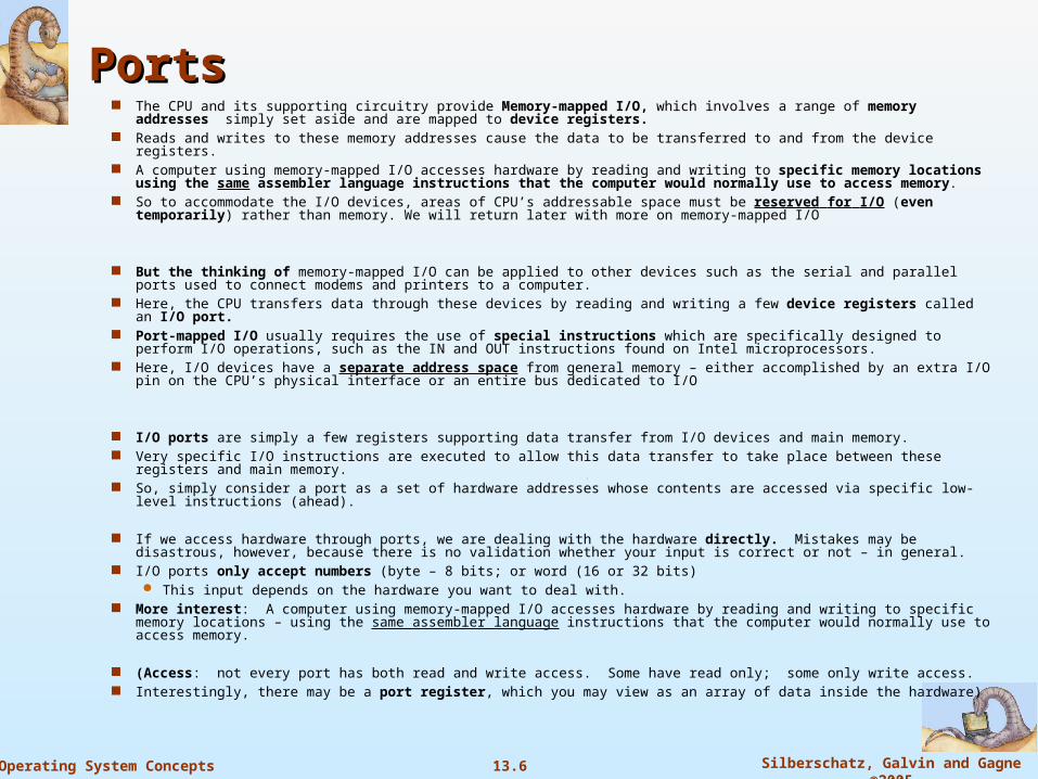
More Modern Port ViewMore Modern Port View
These are typical ports on a more modern computer:

13.9 Silberschatz, Galvin and Gagne ©2005Operating System Concepts
Device I/O Port Locations on PCs (partial)Device I/O Port Locations on PCs (partial)
Here, you can see some of the addresses set aside to support I/O
13.10 Silberschatz, Galvin and Gagne ©2005Operating System Concepts
BusesBuses
In computer architecture, a bus is a subsystem that transfers data between computer components inside a computer or between computers.
Unlike a point-to-point connection, a bus can logically connect several peripherals over the same set of wires.
Each bus defines its set of connectors to physically plug devices, cards or cables together.
Modern computer buses can use both parallel and bit-serial connections, and can be wired in either a multi-drop (electrical parallel) or daisy chain topology, or connected by switched hubs, as in the case of USB.
Simply stated, however, a bus is just a set of wires with carefully defined protocols that specify a set of messages that can be sent on the wires.
Different patterns of electrical voltages are applied to the wires with defined timings.

13.11 Silberschatz, Galvin and Gagne ©2005Operating System Concepts
Buses: Parallel and Serial; Internal and External; Buses: Parallel and Serial; Internal and External; Blurring with new technologies… Blurring with new technologies…
Parallel buses carry data words in parallel on multiple wires; Serial buses carry data in bit-serial form.
As data rates increase, the problems of timing skew, power consumption, electromagnetic interference and crosstalk across parallel buses become more and more difficult to avoid
Often, a serial bus can actually be operated at higher overall data rates than a parallel bus, despite having fewer electrical connections, because a serial bus inherently has no timing skew or crosstalk.
Most computers have both internal and external buses. Internal bus connects all the internal components of a computer to the motherboard (and thus, the
CPU and internal memory). Also called local bus, because they are intended to connect to local devices, not to those in other machines or external to the computer.
External bus connects external peripherals to the motherboard.
Network connections such as Ethernet are not generally regarded as buses, although the difference is largely conceptual rather than practical.
The arrival of technologies is blurring the boundaries between networks and buses. Lines between internal and external are sometimes fuzzy; some newer technologies are
intended to replace both internal buses like PCI as well as external ones like Fibre Channel. In the typical desktop application, USB serves as a peripheral bus, but it also sees some use
as a networking utility and for connectivity between different computers, again blurring the distinctions.

13.12 Silberschatz, Galvin and Gagne ©2005Operating System Concepts
Bus Topology - NetworkBus Topology - Network
Here, we need a master scheduler to control frequencies, priorities and data traffic.
For data transfer, requesting computer sends a message to the scheduler, which puts the request into a queue.
Message contains an identification code which is broadcast to all nodes of the network.
The scheduler works out priorities and notifies the receiver as soon as the bus is available.
The identified node takes the message and performs the data transfer between the two computers.
When data transfer is completed, bus becomes free for the next request in the scheduler's queue.
Bus Benefit: any computer can be accessed directly and messages can be sent in a relatively simple and fast way.
Bus Disadvantage: needs a scheduler to assign frequencies and priorities to organize the traffic.

13.13 Silberschatz, Galvin and Gagne ©2005Operating System Concepts
Examples of Internal Computer BusesExamples of Internal Computer BusesYou may have heard of a few of these… (several omitted for space)
Parallel:
Extended ISA or EISA
Industry Standard Architecture or ISA
Low Pin Count or LPC
Micro Channel or MCA
MBus
Multibus for industrial systems
Peripheral Component Interconnect or PCI
S-100 bus or IEEE 696, used in the Altair and similar microcomputers
SBus or IEEE 1496
VESA Local Bus or VLB or VL-bus
VMEbus, the VERSAmodule Eurocard bus
STD Bus for 8- and 16-bit microprocessor systems
Unibus
Q-Bus
Serial
1-Wire
Hyper Transport
I²C
PCI Express or PCIe
Serial Peripheral Interface Bus or SPI bus
FireWire i.Link or IEEE 1394
13.14 Silberschatz, Galvin and Gagne ©2005Operating System Concepts
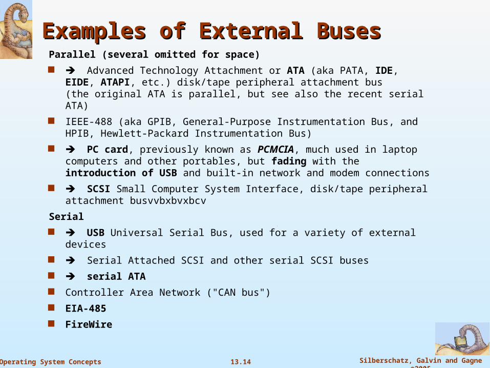
Examples of External BusesExamples of External BusesParallel (several omitted for space)
Advanced Technology Attachment or ATA (aka PATA, IDE, EIDE, ATAPI, etc.) disk/tape peripheral attachment bus(the original ATA is parallel, but see also the recent serial ATA)
IEEE-488 (aka GPIB, General-Purpose Instrumentation Bus, and HPIB, Hewlett-Packard Instrumentation Bus)
PC card, previously known as PCMCIA, much used in laptop computers and other portables, but fading with the introduction of USB and built-in network and modem connections
SCSI Small Computer System Interface, disk/tape peripheral attachment busvvbxbvxbcv
Serial
USB Universal Serial Bus, used for a variety of external devices
Serial Attached SCSI and other serial SCSI buses
serial ATA
Controller Area Network ("CAN bus")
EIA-485
FireWire

13.15 Silberschatz, Galvin and Gagne ©2005Operating System Concepts
Buses - lastlyBuses - lastly
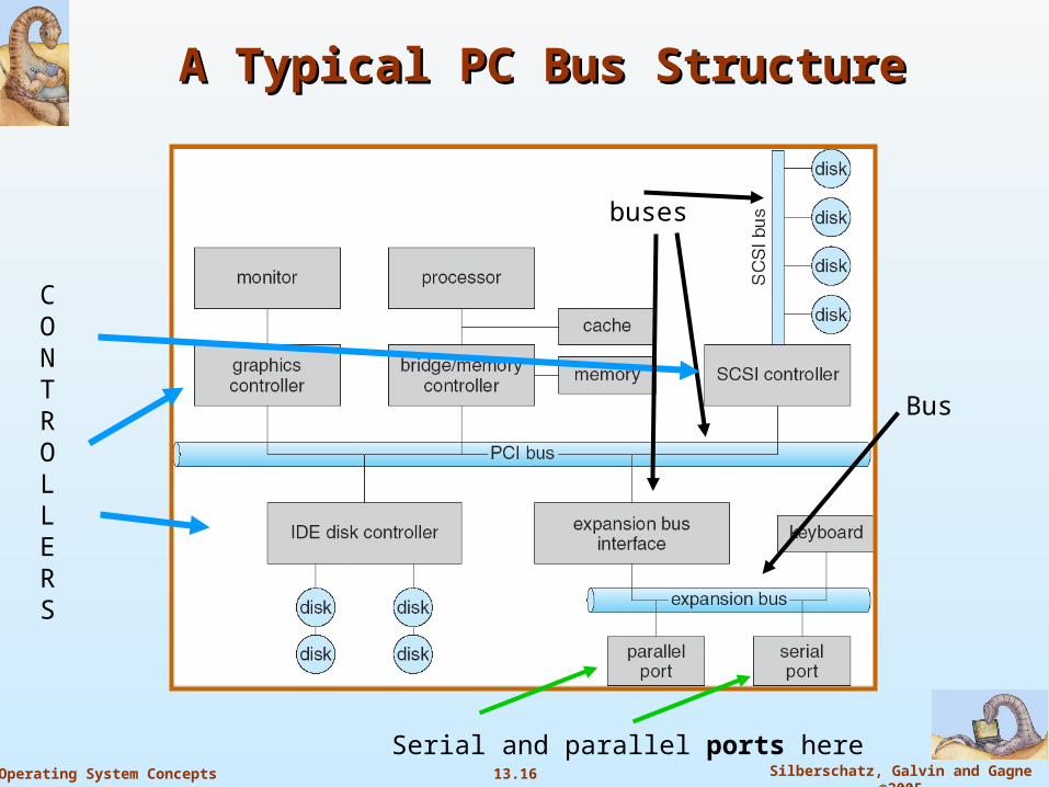
A typical PC bus structure is shown ahead and is a PCI bus.
This bus connects processor-memory subsystems to the fast devices
An expansion bus connects relatively slow devices (keyboard, serial and parallel ports)
Figure also shows four disks connected together via a SCSI bus plugged into a SCSI controller.
13.16 Silberschatz, Galvin and Gagne ©2005Operating System Concepts
A Typical PC Bus StructureA Typical PC Bus Structure
Bus
Serial and parallel ports here
CON TROLLERS
buses

13.17 Silberschatz, Galvin and Gagne ©2005Operating System Concepts
Device ControllersDevice Controllers The device controller is the hardware that controls the communication
between the system and the peripheral drive unit.
They take care of the low level operations such as error checking, moving disk heads, data transfer, and location of data on the device.
There are many types of device controllers in a computer system.
In truth, any device connected to the computer is connected by a plug and socket, and the socket is connected to a device controller.
These device controllers use binary and digital codes and typically have a local buffer, command registers, and more.
Communications – in the transfer of data and the ‘handshaking’ that must take place between device controllers and the CPU is very interesting and very diverse.
We will spend a good bit of time on this head…

13.18 Silberschatz, Galvin and Gagne ©2005Operating System Concepts
Device Controllers - 2 Device Controllers - 2
Controllers operate ports, buses, or devices. A serial controller is simple and controls signals on wires of a serial
port
A SCSI bus controller can be very complex because the SCSI protocol itself is complex and may well control many physical devices connected in quite diverse ways.
SCSI bus controller is often implemented as a separate circuit board (or a host adaptor) that plugs into the computer. The SCSI circuit board may well contain an extra processor,
microcode, and some private memory to enable it to process the SCSI protocol messages.
Microcode and a processor doing may handle bad-sector mapping, pre-fetching, buffering, and caching.
Recall the work that must be done when dealing with RAID architectures!

13.19 Silberschatz, Galvin and Gagne ©2005Operating System Concepts
Setting Up I/O – CPU Communications with Setting Up I/O – CPU Communications with Device ControllersDevice Controllers
Controllers have registers for data and control signals.
Processors communicate with controller by reading and writing bit patterns in these registers (discussed previously and more ahead)
One way to communicate with controller is by reading and writing bit patterns in these registers and enabling control bits and status bites for communications..
Communications can occur by accessing using these registers sometimes with standard assembler like instructions and other times (ahead) via special instructions.
Instructions typically specify the transfer of a byte or word.
Instructions trigger bus lines to select the proper device and to move bits into and out of device registers.
But it is in how this byte/word becomes available for transfer, how the availability of this byte / word is communicated – perhaps to the CPU, and then how the byte/word is actually transferred and then the potential system overhead (response) incurred that presents many issues and variations.

13.20 Silberschatz, Galvin and Gagne ©2005Operating System Concepts
Port I/O and Memory Mapped I/OPort I/O and Memory Mapped I/O Port I/O: Using control signal registers and data registers in the device controller, the processor
can read the status in these registers – can then read or write data (bit patterns) using (as stated) typical low-level I/O instructions that result in transferred data to/from these registers to/from an I/O port.
These instructions send signals that result in moving data into/out from these device registers to an I/O port.
Memory-Mapped I/O: Memory-mapped I/O is an I/O scheme where the device's registers themselves (the
device controller’s onboard memory, if you will) are mapped into the processor's address space.
Reads and writes to these memory addresses cause the data to be transferred to and from the device registers and system memory.
(of course, in memory-mapped I/O, then, we have a range of memory addresses set aside to support this mapping to device registers.
It is important to note, as your book cites, that some systems use both I/O instructions to control some devices and memory-mapped I/O to control others. Graphics I/O is a prime example, where (what I am calling) port i/O is used to control (status bits, busy bits, etc.) the devices, but the transfer of data – especially large amounts of data – used the memory-mapped approach. Note the potential for software fault problems, however, using this approach

13.21 Silberschatz, Galvin and Gagne ©2005Operating System Concepts
I/O Ports – Themselves <book>I/O Ports – Themselves <book>
I/O port typically has four registers called the status, control, data-in and data-out.
Data-in register is read by the host to get input.
Data-out register is written to by the host to send output
Status register contains bits that indicate states (current command completed, a byte is available (or not) to be read from the data-in register, and whether a device error has occurred.
Control register – written by host to start a command; change device mode
Can change between full and half-duplex communications
Other bit enables parity checking
Another changes from 7 or 8 bits, etc…
Data registers are normally 1 to four bits.
FIFO Chips. Some controllers have FIFO chips to build several bytes of I or O data to expand the capacity of the controller beyond the size of the data register.
A FIFO chip can hold a small burst of data until the device or host is able to receive the data. (This ‘until’ may become an issue ahead…)

13.22 Silberschatz, Galvin and Gagne ©2005Operating System Concepts
Programmed I/O : Interrupt-Driven I/O Programmed I/O : Interrupt-Driven I/O <different source><different source>
We can use memory-mapped I/O for both serial and parallel ports to connect modems and printers to a computer.
The CPU transfers data through these kinds of devices by reading and writing a few device registers called an I/O port.
To send out a long string of bytes through a memory-mapped serial port, the CPU writes one data byte to the data register, sets a bit in the control register to signal that the byte is available. Device takes the data byte, Device clears the bit in the control register to signal that it is ready for the next
byte. CPU can then transfer the next byte…
If CPU using polling (next slide) to watch the control bit constantly looping to see if device is ready, this is called programmed I/O (PIO)
If the CPU does not poll the control bit but instead receives an interrupt when the device is ready for the next byte, the data transfer is said to be interrupt-driven I/O (more ahead on this)
13.23 Silberschatz, Galvin and Gagne ©2005Operating System Concepts
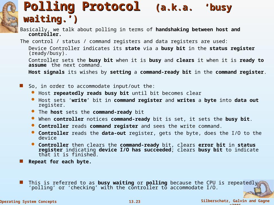
Polling Protocol Polling Protocol (a.k.a. ‘busy waiting.’)(a.k.a. ‘busy waiting.’)Basically, we talk about polling in terms of handshaking between host and controller.
The control / status / command registers and data registers are used:
Device Controller indicates its state via a busy bit in the status register (ready/busy).
Controller sets the busy bit when it is busy and clears it when it is ready to assume the next command.
Host signals its wishes by setting a command-ready bit in the command register.
So, in order to accommodate input/out the: Host repeatedly reads busy bit until bit becomes clear Host sets ‘write’ bit in command register and writes a byte into data out register. The host sets the command-ready bit When controller notices command-ready bit is set, it sets the busy bit. Controller reads command register and sees the write command. Controller reads the data-out register, gets the byte, does the I/O to the device Controller then clears the command-ready bit, clears error bit in status register
indicating device I/O has succeeded; clears busy bit to indicate that it is finished. Repeat for each byte.
This is referred to as busy waiting or polling because the CPU is repeatedly ‘polling’ or ‘checking’ with the controller to accommodate I/O.
13.24 Silberschatz, Galvin and Gagne ©2005Operating System Concepts
Issues in PollingIssues in Polling If controller and device are fast, this is a good method. If not, host should probably switch to another task, which will lead us up to ‘interrupt
processing’ – in much more detail than in previous discussions.
We must be careful here, because once data is ‘stabilized’ in these buffers (and some are small), there’s no guarantee that the data will remain available (stable) for extended periods of time.
For streaming data, this data (like coming in on a serial port) must be handled. It can be lost. These buffer on some devices (keyboard?) are not very large.
For most polling a three-CPU-instruction set (‘get the data’) is very quick. Poll, read and extract using AND instructions, and a BNZ
But if wasted polling takes place where devices are not ready for service and especially where other work may be waiting, we need a better approach.
Perhaps it is better for a device controller to notify a CPU when ready for service rather than, at times, senselessly poll to see if we have I/O completion?
So let’s return to the hardware mechanism that accommodates this: Interrupts. We will look at this in more detail than we typically do when discussing memory management
(virtual memory) and basic I/O.
13.25 Silberschatz, Galvin and Gagne ©2005Operating System Concepts
Interrupts – How they WorkInterrupts – How they Work CPU hardware simply has a wire (interrupt request line) it senses after
executing every instruction.
When the CPU detects signal on the line (set by the controller), the CPU performs a state save and jumps to an interrupt handler routine in a fixed memory location.
Please note: this save state does not necessarily mean context switching!!
Current processing is suspended temporarily (can do context switching in general – but we will discuss this more ahead…)
This interrupt handler determines the cause of the interrupt, performs the processing, restores the previous CPU state, and executes a return from the interrupt to return to the CPU to the execution state prior to the interrupt.
Terminology: the device controller raises an interrupt; the CPU catches the interrupt, and dispatches it to the interrupt handler. The handler clears the interrupt by servicing the device
See process on next slide.

End of Chapter 13-1End of Chapter 13-1
Related Documents