WSDOT Design Manual M 22-01.20 Page 1220-1 September 2021 Chapter 1220 Geometric Profile Elements 1220.01 General 1220.02 Vertical Alignment 1220.03 Coordination of Vertical and Horizontal Alignments 1220.04 Airport Clearance 1220.05 Railroad Crossings 1220.06 Procedures 1220.07 Documentation 1220.08 References Exhibit 1220-1 Minimum Length of Sag Vertical Curves Exhibit 1220-2 Grade Length Exhibit 1220-3 Coordination of Horizontal and Vertical Alignments Exhibit 1220-4 Coordination of Horizontal and Vertical Alignments Exhibit 1220-5 Coordination of Horizontal and Vertical Alignments Exhibit 1220-6 Grading at Railroad Crossings 1220.01 General Vertical alignment (roadway profile) consists of a series of gradients connected by vertical curves. It is mainly controlled by the following: • Topography • Class of highway • Horizontal alignment • Safety • Sight distance • Construction costs • Drainage • Adjacent land use • Vehicular characteristics • Aesthetics This chapter provides guidance for the design of vertical alignment. For additional information, see the following chapters: Chapter Subject Chapter 1103 Design controls, terrain Chapter 1210 Horizontal alignment Chapter 1260 Sight distance Chapter 1310 Grades at intersections Chapter 1360 Maximum grade for ramps

Welcome message from author
This document is posted to help you gain knowledge. Please leave a comment to let me know what you think about it! Share it to your friends and learn new things together.
Transcript
WSDOT Design Manual M 22-01.20 Page 1220-1
September 2021
Chapter 1220 Geometric Profile Elements
1220.01 General
1220.02 Vertical Alignment
1220.03 Coordination of Vertical and Horizontal Alignments
1220.04 Airport Clearance
1220.05 Railroad Crossings
1220.06 Procedures
1220.07 Documentation
1220.08 References
Exhibit 1220-1 Minimum Length of Sag Vertical Curves
Exhibit 1220-2 Grade Length
Exhibit 1220-3 Coordination of Horizontal and Vertical Alignments
Exhibit 1220-4 Coordination of Horizontal and Vertical Alignments
Exhibit 1220-5 Coordination of Horizontal and Vertical Alignments
Exhibit 1220-6 Grading at Railroad Crossings
1220.01 General
Vertical alignment (roadway profile) consists of a series of gradients connected by vertical curves. It is mainly
controlled by the following:
• Topography
• Class of highway
• Horizontal alignment
• Safety
• Sight distance
• Construction costs
• Drainage
• Adjacent land use
• Vehicular characteristics
• Aesthetics
This chapter provides guidance for the design of vertical alignment. For additional information, see the following
chapters:
Chapter Subject
Chapter 1103 Design controls, terrain
Chapter 1210 Horizontal alignment
Chapter 1260 Sight distance
Chapter 1310 Grades at intersections
Chapter 1360 Maximum grade for ramps
Chapter 1220 Geometric Profile Elements
WSDOT Design Manual M 22-01.20 Page 1220-2
September 2021
1220.02 Vertical Alignment
1220.02(1) Design Principles
The following are general principles for developing vertical alignment (also see Exhibit 1220-3 through Exhibit
1220-5):
• Use a smooth grade line with gradual changes, consistent with the context identification and character
of terrain. Avoid numerous breaks and short grades.
• Avoid “roller coaster” or “hidden dip” profiles by use of gradual grades made possible by heavier cuts
and fills or by introducing some horizontal curvature in conjunction with the vertical curvature.
• Avoid grades that affect truck speeds and, therefore, traffic operations.
• Avoid broken back grade lines with short tangents between two vertical curves.
• Use long vertical curves to flatten grades near the top of long, steep grades.
• Where at-grade intersections occur on roadways with moderate to steep grades, it is desirable to flatten
or reduce the grade through the intersection.
• Establish the subgrade at least 1 foot above the high water table (real or potential), or as recommended
by the Region Materials Engineer. Consider the low side of superelevated roadways.
• When a vertical curve takes place partly or wholly in a horizontal curve, coordinate the two as discussed
in Section 1220.03.
1220.02(2) Minimum Length of Vertical Curves (Section rewritten September 2021)
The minimum length of a vertical curve is controlled by design speed, stopping sight distance, and the change in
grade.
1220.02(2)(a) New Construction Projects
For new construction (building a street where one does not currently exist), the minimum length of the vertical
curve must meet stopping sight distance (see Chapter 1260) or have a length at least three times the design
speed, whichever is greater. For aesthetics, the desirable length of a vertical curve is two to three times the
length needed for stopping sight distance.
1220.02(2)(b) Reconstruction Projects
On reconstruction projects, a zero-length vertical curve may be used as follows:
• Intermediate and Low Speeds: Algebraic difference of 1.0% or less
• High Speeds: Algebraic Difference of 0.5% or less
Zero-length vertical curves are meant for spot locations to accommodate small profile changes that match into
existing profiles. For example, modifying the existing profile for an overlay or adjusting the profile to
accommodate a fish passage structure. Do not use a series of zero-length vertical curves as a replacement for a
properly designed vertical curve.
The minimum length of crest vertical curves shall be the same as new construction.
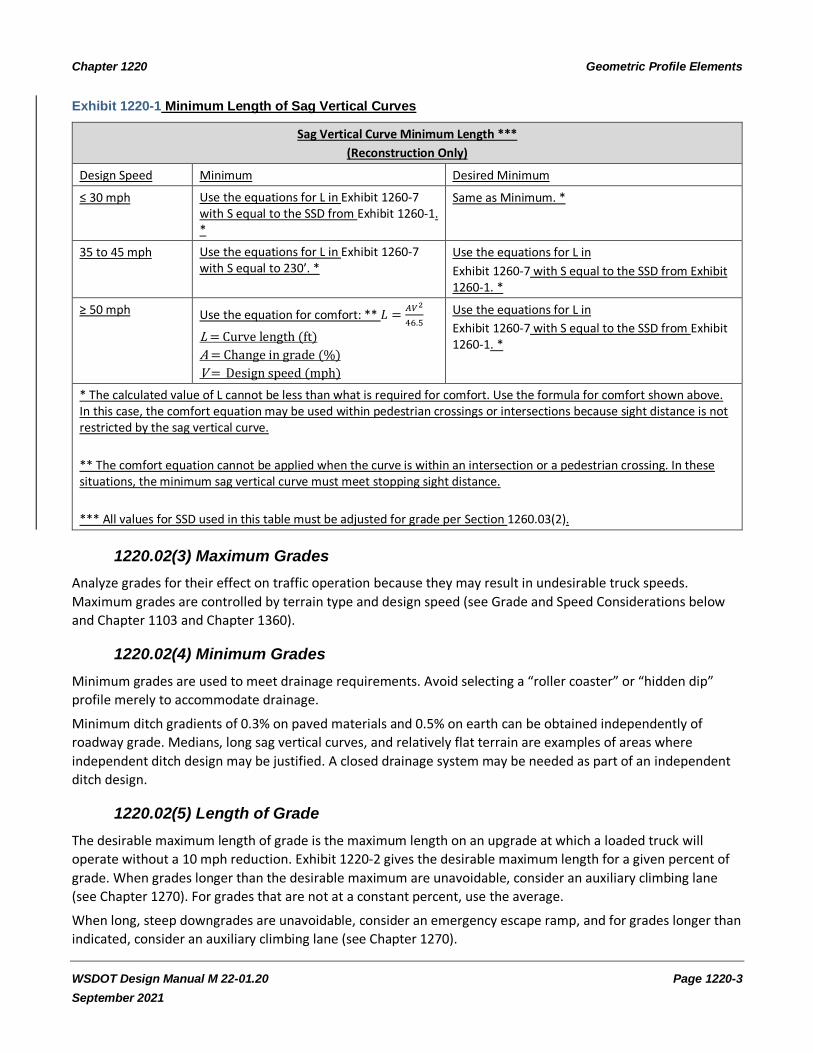
The minimum length of sag vertical curves is determined using Exhibit 1220-1. There are two minimum lengths
listed in Exhibit 1220-1: minimum and desired minimum. Try to meet the desired minimum as it provides more
sight distance for nighttime driving. If you are unable to meet the desired minimums and must drop to the
minimum, document your decision in the Design Documentation Package. A spreadsheet is available on the
Design Support website to calculate the minimum and desired minimum shown in Exhibit 1220-1.
Chapter 1220 Geometric Profile Elements
WSDOT Design Manual M 22-01.20 Page 1220-3
September 2021
Exhibit 1220-1 Minimum Length of Sag Vertical Curves
Sag Vertical Curve Minimum Length ***
(Reconstruction Only)
Design Speed Minimum Desired Minimum
≤ 30 mph Use the equations for L in Exhibit 1260-7 with S equal to the SSD from Exhibit 1260-1. *
Same as Minimum. *
35 to 45 mph Use the equations for L in Exhibit 1260-7 with S equal to 230’. *
Use the equations for L in
Exhibit 1260-7 with S equal to the SSD from Exhibit 1260-1. *
≥ 50 mph Use the equation for comfort: ** 𝐿 =𝐴𝑉2
46.5
L = Curve length (ft)
A = Change in grade (%)
V = Design speed (mph)
Use the equations for L in
Exhibit 1260-7 with S equal to the SSD from Exhibit 1260-1. *
* The calculated value of L cannot be less than what is required for comfort. Use the formula for comfort shown above. In this case, the comfort equation may be used within pedestrian crossings or intersections because sight distance is not restricted by the sag vertical curve.
** The comfort equation cannot be applied when the curve is within an intersection or a pedestrian crossing. In these situations, the minimum sag vertical curve must meet stopping sight distance.
*** All values for SSD used in this table must be adjusted for grade per Section 1260.03(2).
1220.02(3) Maximum Grades
Analyze grades for their effect on traffic operation because they may result in undesirable truck speeds.
Maximum grades are controlled by terrain type and design speed (see Grade and Speed Considerations below
and Chapter 1103 and Chapter 1360).
1220.02(4) Minimum Grades
Minimum grades are used to meet drainage requirements. Avoid selecting a “roller coaster” or “hidden dip”
profile merely to accommodate drainage.
Minimum ditch gradients of 0.3% on paved materials and 0.5% on earth can be obtained independently of
roadway grade. Medians, long sag vertical curves, and relatively flat terrain are examples of areas where
independent ditch design may be justified. A closed drainage system may be needed as part of an independent
ditch design.
1220.02(5) Length of Grade
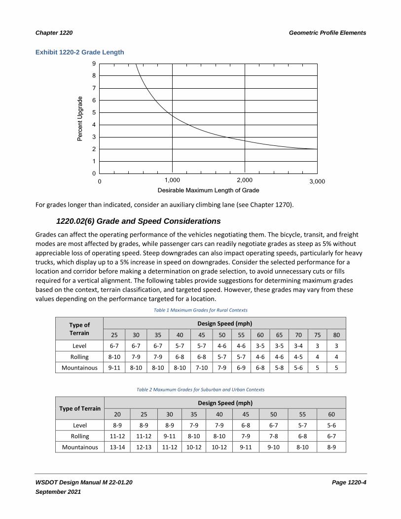
The desirable maximum length of grade is the maximum length on an upgrade at which a loaded truck will
operate without a 10 mph reduction. Exhibit 1220-2 gives the desirable maximum length for a given percent of
grade. When grades longer than the desirable maximum are unavoidable, consider an auxiliary climbing lane
(see Chapter 1270). For grades that are not at a constant percent, use the average.
When long, steep downgrades are unavoidable, consider an emergency escape ramp, and for grades longer than
indicated, consider an auxiliary climbing lane (see Chapter 1270).
Chapter 1220 Geometric Profile Elements
WSDOT Design Manual M 22-01.20 Page 1220-4
September 2021
Exhibit 1220-2 Grade Length
Desirable Maximum Length of Grade
1,0000 2,000 3,000
0
2
4
6
7
9
8
5
3
1
Pe
rce
nt
Up
gra
de
For grades longer than indicated, consider an auxiliary climbing lane (see Chapter 1270).
1220.02(6) Grade and Speed Considerations
Grades can affect the operating performance of the vehicles negotiating them. The bicycle, transit, and freight
modes are most affected by grades, while passenger cars can readily negotiate grades as steep as 5% without
appreciable loss of operating speed. Steep downgrades can also impact operating speeds, particularly for heavy
trucks, which display up to a 5% increase in speed on downgrades. Consider the selected performance for a
location and corridor before making a determination on grade selection, to avoid unnecessary cuts or fills
required for a vertical alignment. The following tables provide suggestions for determining maximum grades
based on the context, terrain classification, and targeted speed. However, these grades may vary from these
values depending on the performance targeted for a location.
Table 1 Maximum Grades for Rural Contexts
Type of Terrain
Design Speed (mph)
25 30 35 40 45 50 55 60 65 70 75 80
Level 6-7 6-7 6-7 5-7 5-7 4-6 4-6 3-5 3-5 3-4 3 3
Rolling 8-10 7-9 7-9 6-8 6-8 5-7 5-7 4-6 4-6 4-5 4 4
Mountainous 9-11 8-10 8-10 8-10 7-10 7-9 6-9 6-8 5-8 5-6 5 5
Table 2 Maxumum Grades for Suburban and Urban Contexts
Type of Terrain Design Speed (mph)
20 25 30 35 40 45 50 55 60
Level 8-9 8-9 8-9 7-9 7-9 6-8 6-7 5-7 5-6
Rolling 11-12 11-12 9-11 8-10 8-10 7-9 7-8 6-8 6-7
Mountainous 13-14 12-13 11-12 10-12 10-12 9-11 9-10 8-10 8-9
Chapter 1220 Geometric Profile Elements
WSDOT Design Manual M 22-01.20 Page 1220-5
September 2021
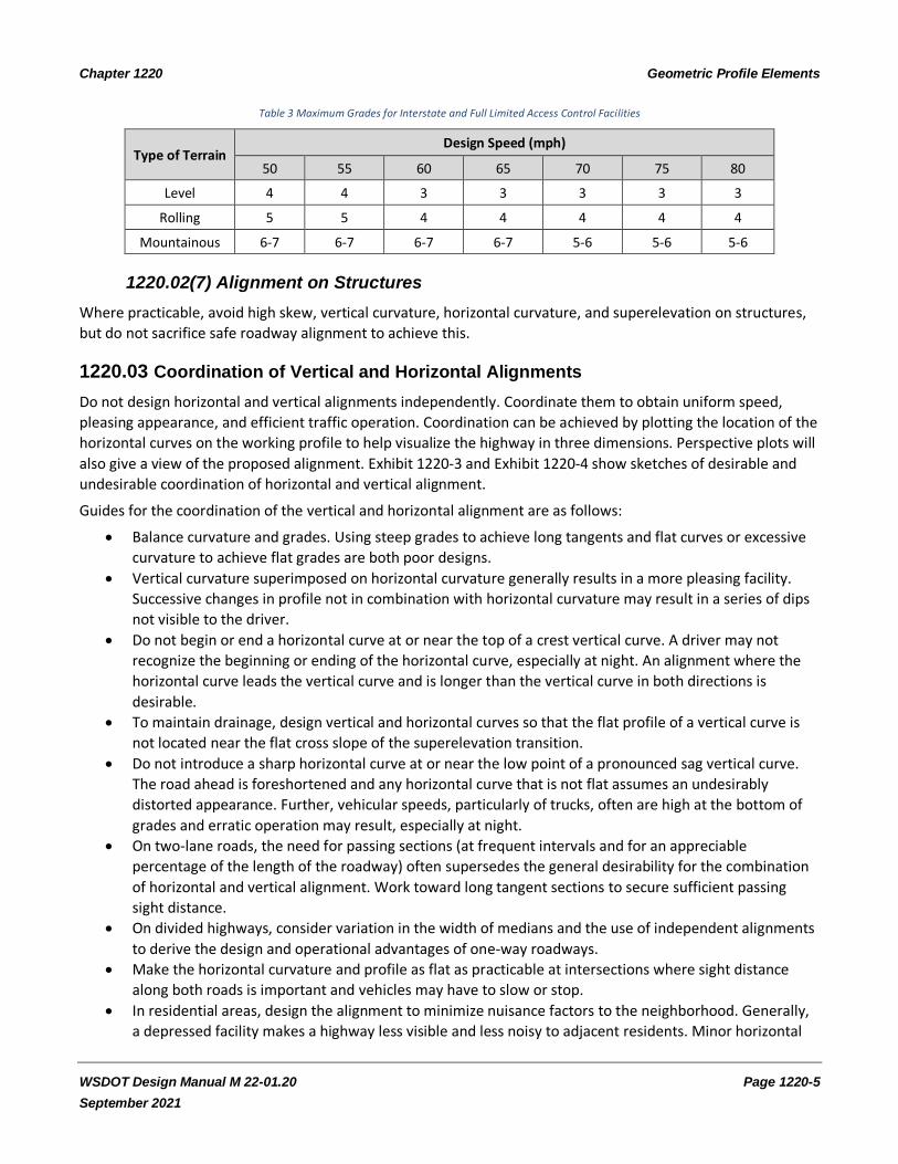
Table 3 Maximum Grades for Interstate and Full Limited Access Control Facilities
Type of Terrain Design Speed (mph)
50 55 60 65 70 75 80
Level 4 4 3 3 3 3 3
Rolling 5 5 4 4 4 4 4
Mountainous 6-7 6-7 6-7 6-7 5-6 5-6 5-6
1220.02(7) Alignment on Structures
Where practicable, avoid high skew, vertical curvature, horizontal curvature, and superelevation on structures,
but do not sacrifice safe roadway alignment to achieve this.
1220.03 Coordination of Vertical and Horizontal Alignments
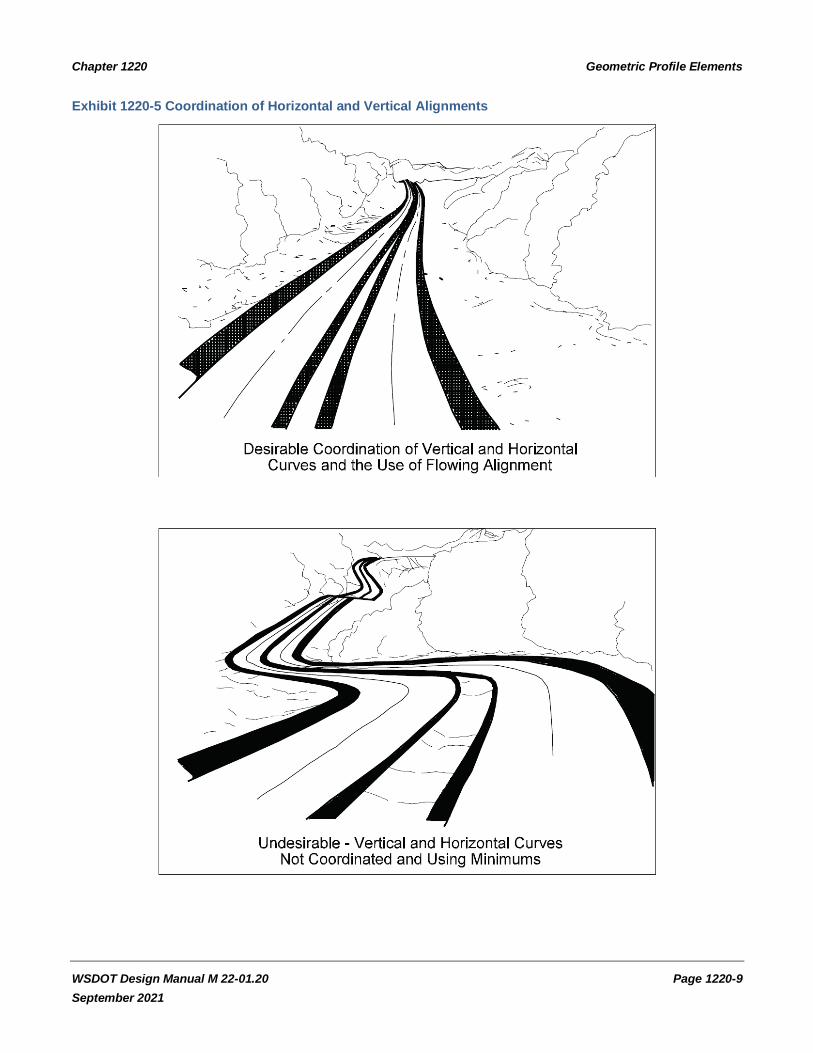
Do not design horizontal and vertical alignments independently. Coordinate them to obtain uniform speed,
pleasing appearance, and efficient traffic operation. Coordination can be achieved by plotting the location of the
horizontal curves on the working profile to help visualize the highway in three dimensions. Perspective plots will
also give a view of the proposed alignment. Exhibit 1220-3 and Exhibit 1220-4 show sketches of desirable and
undesirable coordination of horizontal and vertical alignment.
Guides for the coordination of the vertical and horizontal alignment are as follows:
• Balance curvature and grades. Using steep grades to achieve long tangents and flat curves or excessive
curvature to achieve flat grades are both poor designs.
• Vertical curvature superimposed on horizontal curvature generally results in a more pleasing facility.
Successive changes in profile not in combination with horizontal curvature may result in a series of dips
not visible to the driver.
• Do not begin or end a horizontal curve at or near the top of a crest vertical curve. A driver may not
recognize the beginning or ending of the horizontal curve, especially at night. An alignment where the
horizontal curve leads the vertical curve and is longer than the vertical curve in both directions is
desirable.
• To maintain drainage, design vertical and horizontal curves so that the flat profile of a vertical curve is
not located near the flat cross slope of the superelevation transition.
• Do not introduce a sharp horizontal curve at or near the low point of a pronounced sag vertical curve.
The road ahead is foreshortened and any horizontal curve that is not flat assumes an undesirably
distorted appearance. Further, vehicular speeds, particularly of trucks, often are high at the bottom of
grades and erratic operation may result, especially at night.
• On two-lane roads, the need for passing sections (at frequent intervals and for an appreciable
percentage of the length of the roadway) often supersedes the general desirability for the combination
of horizontal and vertical alignment. Work toward long tangent sections to secure sufficient passing
sight distance.
• On divided highways, consider variation in the width of medians and the use of independent alignments
to derive the design and operational advantages of one-way roadways.
• Make the horizontal curvature and profile as flat as practicable at intersections where sight distance
along both roads is important and vehicles may have to slow or stop.
• In residential areas, design the alignment to minimize nuisance factors to the neighborhood. Generally,
a depressed facility makes a highway less visible and less noisy to adjacent residents. Minor horizontal
Chapter 1220 Geometric Profile Elements
WSDOT Design Manual M 22-01.20 Page 1220-6
September 2021
adjustments can sometimes be made to increase the buffer zone between the highway and clusters of
homes.
• Design the alignment to enhance attractive scenic views of the natural and constructed environment,
such as rivers, rock formations, parks, and outstanding buildings.
When superelevation transitions fall within the limits of a vertical curve, plot profiles of the edges of pavement
and check for smooth transitions.
1220.04 Airport Clearance
Contact the airport authorities early for proposed highway construction or alteration in the vicinity of a public or
military airport, so that advance planning and design work can proceed within the required Federal Aviation
Administration (FAA) regulations (see the Environmental Manual).
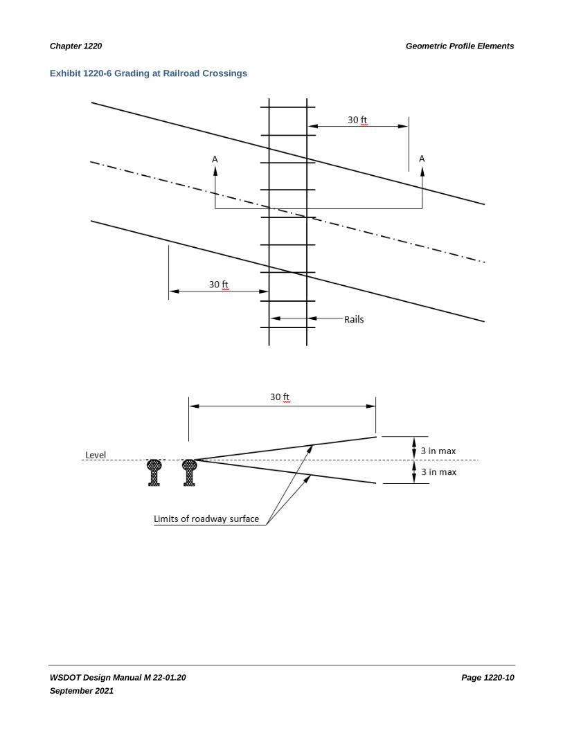
1220.05 Railroad Crossings
When a highway crosses a railroad at grade, design the highway grade to prevent low-hung vehicles from
damaging the rails or getting hung up on the tracks. Exhibit 1220-6 gives guidance on designing highway grades
at railroad crossings. For more information on railroad-highway crossings, see Chapter 1350.
1220.06 Procedures
When the project modifies the vertical alignment, develop vertical alignment plans for inclusion in the Plans,
Specifications, and Estimates (PS&E) to a scale suitable for showing vertical alignment for all proposed
roadways, including ground line, grades, vertical curves, and superelevation. (See the Plans Preparation Manual
for guidance.) When justifying any modification to the vertical alignment, include the reasons for the change,
alternatives addressed (if any) and why the selected alternative was chosen.
When the profile is a result of new horizontal alignment, develop vertical and horizontal alignments together,
and include the profile with the horizontal alignment justification.
1220.07 Documentation
Refer to Chapter 300 for design documentation requirements.
1220.08 References
1220.08(1) Federal/State Laws and Codes
Washington Administrative Code (WAC) 468-18-040, Design standards for rearranged county roads, frontage
roads, access roads, intersections, ramps and crossings
1220.08(2) Design Guidance
Local Agency Guidelines (LAG), M 36-63, WSDOT
Manual on Uniform Traffic Control Devices for Streets and Highways, USDOT, FHWA; as adopted and modified by
Chapter 468-95 WAC “Manual on uniform traffic control devices for streets and highways” (MUTCD)
Plans Preparation Manual, M 22-31, WSDOT
Chapter 1220 Geometric Profile Elements
WSDOT Design Manual M 22-01.20 Page 1220-7
September 2021
1220.08(3) Supporting Information
A Policy on Geometric Design of Highways and Streets (Green Book), AASHTO, current edition
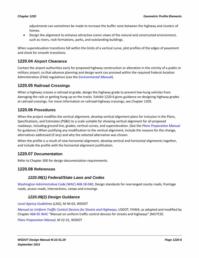
Exhibit 1220-3 Coordination of Horizontal and Vertical Alignments
Horizontal curve
Crest vertical curve
Coinciding Horizontal and Crest Vertical Curves
When horizontal and crest vertical curves coincide, a satisfactory appearance results.
Horizontal curve
Sag vertical curve
Coinciding Horizontal and Sag Vertical Curves
When horizontal and sag vertical curves coincide, a satisfactory appearance results.
Crest vertical curve
Horizontal alignment
Short Tangent on a Crest Between Two Horizontal Curves
This combination is deficient for several reasons:
• The curve reversal is on a crest, making the second curve less visible.
• The tangent is too short for the superelevation transition.
• The flat area of the superelevation transition will be near the flat grade in the crest.
Chapter 1220 Geometric Profile Elements
WSDOT Design Manual M 22-01.20 Page 1220-8
September 2021
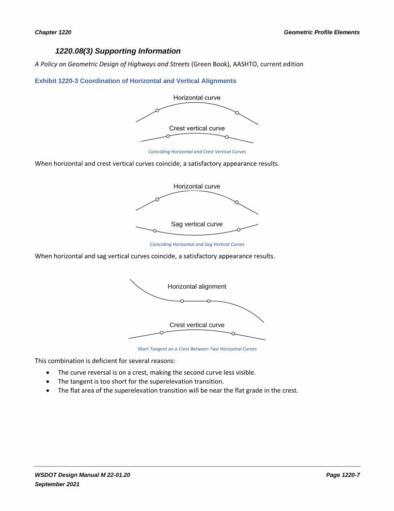
Exhibit 1220-4 Coordination of Horizontal and Vertical Alignments
Profile
Desirable profile
Horizontal tangent
Profile with Tangent Alignment
Avoid designing dips on an otherwise long uniform grade.
Sag vertical curve
Horizontal curve
Sharp Angle Appearance
This combination presents a poor appearance. The horizontal curve looks like a sharp angle.
Perspective
Horizontal alignment
Profile
Line of sight
Disjointed Effect
A disjointed effect occurs when the beginning of a horizontal curve is hidden by an intervening crest while the
continuation of the curve is visible in the distance beyond the intervening crest.
Chapter 1220 Geometric Profile Elements
WSDOT Design Manual M 22-01.20 Page 1220-9
September 2021
Exhibit 1220-5 Coordination of Horizontal and Vertical Alignments
Chapter 1220 Geometric Profile Elements
WSDOT Design Manual M 22-01.20 Page 1220-10
September 2021
Exhibit 1220-6 Grading at Railroad Crossings
Related Documents


