P ART FOUR Part Four examines the internal mechanisms and user-network interfaces that have been developed to support voice, data, and multimedia communications over long- distance networks. The traditional technologies of packet switching and circuit switching are examined,as well as the more recent ATM and wireless WANs. ROAD MAP FOR PART FOUR Chapter 12 Circuit Switching and Packet Switching Chapter 12 introduces the concept of network switching techniques. The chapter then introduces the two traditional approaches to wide area networking: circuit switching and packet switching. With circuit switching, a key design issue is that of control signaling, and this area is explored. The remainder of Chapter 12 introduces packet-switching technology. The chapter covers the basic principles of packet switching and analyzes datagram and virtual circuit approaches. Chapter 13 Frame Relay and ATM Frame relay is in essence a packet-switching technology, but it is more streamlined and efficient than traditional packet switching and is designed to support higher data rates.ATM, also known as cell relay, is also a packet-switching technology; it is even more streamlined than frame relay and is designed for very high data rates. Chapter 13 looks at the protocols and design issues involved in both frame relay and ATM. Chapter 14 Wireless WANs Chapter 14 begins with a discussion of the important design issues related to cellu- lar wireless networks.The chapter then looks at issues of multiple access, with a spe- cial emphasis on code-division multiple access (CDMA), which is becoming the dominant cellular transmission technology. Chapter 14 next looks at issues related to third-generation cellular networks.The remainder of Chapter 14 deals with satel- lite communications. Wide Area Networks 342 Business Data Communications, Sixth Edition, by William Stallings. Published by Prentice Hall. Copyright © 2009 by Pearson Education, Inc. ISBN 0-558-69515-9

Welcome message from author
This document is posted to help you gain knowledge. Please leave a comment to let me know what you think about it! Share it to your friends and learn new things together.
Transcript
PART FOUR
Part Four examines the internal mechanisms and user-network interfaces that havebeen developed to support voice, data, and multimedia communications over long-distance networks. The traditional technologies of packet switching and circuitswitching are examined, as well as the more recent ATM and wireless WANs.
ROAD MAP FOR PART FOUR
Chapter 12 Circuit Switching and Packet SwitchingChapter 12 introduces the concept of network switching techniques. The chapterthen introduces the two traditional approaches to wide area networking: circuitswitching and packet switching. With circuit switching, a key design issue is that ofcontrol signaling, and this area is explored. The remainder of Chapter 12 introducespacket-switching technology. The chapter covers the basic principles of packetswitching and analyzes datagram and virtual circuit approaches.
Chapter 13 Frame Relay and ATMFrame relay is in essence a packet-switching technology, but it is more streamlinedand efficient than traditional packet switching and is designed to support higherdata rates. ATM, also known as cell relay, is also a packet-switching technology; it iseven more streamlined than frame relay and is designed for very high data rates.Chapter 13 looks at the protocols and design issues involved in both frame relay andATM.
Chapter 14 Wireless WANsChapter 14 begins with a discussion of the important design issues related to cellu-lar wireless networks.The chapter then looks at issues of multiple access, with a spe-cial emphasis on code-division multiple access (CDMA), which is becoming thedominant cellular transmission technology. Chapter 14 next looks at issues relatedto third-generation cellular networks. The remainder of Chapter 14 deals with satel-lite communications.
Wide Area Networks
342
Business Data Communications, Sixth Edition, by William Stallings. Published by Prentice Hall. Copyright © 2009 by Pearson Education, Inc.
ISB
N0-558-69515-9

CIRCUIT SWITCHING AND PACKETSWITCHING
12.1 Switching Techniques
12.2 Circuit-Switching NetworksBasic OperationControl SignalingSoftswitch Architecture
12.3 Packet-Switching NetworksBasic OperationSwitching Technique
12.4 Traditional Wide Area Network AlternativesWide Area Networks for VoiceWide Area Networks for Data
12.5 Summary
12.6 Recommended Reading and Web Sites
12.7 Key Terms, Review Questions, and Problems
343
CHAPTER
Business Data Communications, Sixth Edition, by William Stallings. Published by Prentice Hall. Copyright © 2009 by Pearson Education, Inc.
ISB
N0-
558-
6951
5-9

This chapter begins with a general discussion of switched communications networks.The remainder of the chapter focuses on wide area networks and, in particular, on tradi-tional approaches to wide area network design: circuit switching and packet switching.
12.1 SWITCHING TECHNIQUES
For transmission of data1 beyond a local area, communication is typically achievedby transmitting data from source to destination through a network of intermediateswitching nodes; this switched network design is typically used to implement LANsas well. The switching nodes are not concerned with the content of the data; rather,their purpose is to provide a switching facility that will move the data from node tonode until they reach their destination. Figure 12.1 illustrates a simple network. Theend devices that wish to communicate may be referred to as stations. The stationsmay be computers, terminals, telephones, or other communicating devices. We shallrefer to the switching devices whose purpose is to provide communication as nodes.The nodes are connected to one another in some topology by transmission links.Each station attaches to a node, and the collection of nodes is referred to as acommunications network.
In a switched communication network, data entering the network from astation are routed to the destination by being switched from node to node. For ex-ample, in Figure 12.1, data from station A intended for station F are sent to node 4.They may then be routed via nodes 5 and 6 or nodes 7 and 6 to the destination.Several observations are in order:
1. Some nodes connect only to other nodes (e.g., 5 and 7). Their sole task is theinternal (to the network) switching of data. Other nodes have one or more
Chapter Objectives
After reading this chapter, you should be able to
♦ Explain the need for a communications network for wide area voice and datacommunications.
♦ Define circuit switching and describe the key elements of circuit-switching networks.
♦ Discuss the important applications of circuit switching, including public networks, pri-vate networks, and software-defined networks.
♦ Define packet switching and describe the key elements of packet-switching technology.
♦ Discuss the important applications of packet switching, including public and privatenetworks.
♦ Discuss the relative merits of circuit switching and packet switching and analyze thecircumstances for which each is most appropriate.
1We use this term here in a very general sense, to include audio, image, and video, as well as ordinary data(e.g., numerical, text).
344 CHAPTER 12 / CIRCUIT SWITCHING AND PACKET SWITCHING
Business Data Communications, Sixth Edition, by William Stallings. Published by Prentice Hall. Copyright © 2009 by Pearson Education, Inc.
ISB
N0-558-69515-9

12.2 / CIRCUIT-SWITCHING NETWORKS 345
stations attached as well; in addition to their switching functions, such nodesaccept data from and deliver data to the attached stations.
2. Node-station links are generally dedicated point-to-point links. Node-node linksare usually multiplexed links, using either frequency division multiplexing(FDM) or some form of time division multiplexing (TDM).
3. Usually, the network is not fully connected; that is, there is not a direct link be-tween every possible pair of nodes. However, it is always desirable to havemore than one possible path through the network for each pair of stations.This enhances the reliability of the network.
Two different technologies are used in wide area switched networks: circuitswitching and packet switching. These two technologies differ in the way the nodesswitch information from one link to another on the way from source to destination.In the remainder of this chapter, we look at the details of both of these technologies.
12.2 CIRCUIT-SWITCHING NETWORKS
Basic Operation
Circuit switching is still the dominant technology for voice communications today,although the volume of packet-based voice communication continues to grow. Com-munication via circuit switching implies that there is a dedicated communication
B
A
E
F
C
D
1
4
5
2
3
6
7
Personalcomputer
Personalcomputer
Mainframe
Switchingnode
Personalcomputer
Personalcomputer
Server
Figure 12.1 Simple Switching Network
Business Data Communications, Sixth Edition, by William Stallings. Published by Prentice Hall. Copyright © 2009 by Pearson Education, Inc.
ISB
N0-
558-
6951
5-9

path between two stations. That path is a connected sequence of links between net-work nodes. On each physical link, a channel is dedicated to the connection. Themost common example of circuit switching is the telephone network.
Communication via circuit switching involves three phases, which can be ex-plained with reference to Figure 12.1.
1. Circuit establishment. Before any signals can be transmitted, an end-to-end(station-to-station) circuit must be established. For example, station A sends arequest to node 4 requesting a connection to station E. Typically, the link fromA to 4 is a dedicated line, so that part of the connection already exists. Node 4must find the next leg in a route leading to E. Based on routing informationand measures of availability and perhaps cost, node 4 selects the link to node5, allocates a free channel (using FDM or TDM) on that link and sends a mes-sage requesting connection to E. So far, a dedicated path has been establishedfrom A through 4 to 5. Because a number of stations may attach to 4, it mustbe able to establish internal paths from multiple stations to multiple nodes.How this is done is discussed later in this section.The remainder of the processproceeds similarly. Node 5 allocates a channel to node 6 and internally ties thatchannel to the channel from node 4. Node 6 completes the connection to E. Incompleting the connection, a test is made to determine if E is busy or is pre-pared to accept the connection.
2. Data transfer. Data can now be transmitted from A through the network to E.The transmission may be analog voice, digitized voice, or binary data, dependingon the nature of the network.As the carriers evolve to fully integrated digital net-works, the use of digital (binary) transmission for both voice and data is becom-ing the dominant method. The path is as follows: A-4 link, internal switchingthrough 4, 4-5 channel, internal switching through 5, 5-6 channel, internal switch-ing through 6, 6-E link. Generally, the connection is full duplex, and signals maybe transmitted in both directions simultaneously.
3. Circuit disconnect. After some period of data transfer, the connection is ter-minated, usually by the action of one of the two stations. Signals must be prop-agated to nodes 4, 5, and 6 to deallocate the dedicated resources.
Note that the connection path is established before data transmission begins.Thus, channel capacity must be reserved between each pair of nodes in the path andeach node must have available internal switching capacity to handle the requestedconnection. The switches must have the intelligence to make these allocations andto devise a route through the network.
Circuit switching can be rather inefficient. Channel capacity is dedicated forthe duration of a connection, even if no data are being transferred. For a voice con-nection, utilization may be rather high, but it still does not approach 100%. For aclient/server connection, the capacity may be idle during most of the time of theconnection. In terms of performance, there is a delay prior to signal transfer for callestablishment. However, once the circuit is established, the network is effectivelytransparent to the users. Information is transmitted at a fixed data rate with nodelay other than the propagation delay through the transmission links. The delay ateach node is negligible.
346 CHAPTER 12 / CIRCUIT SWITCHING AND PACKET SWITCHING
Business Data Communications, Sixth Edition, by William Stallings. Published by Prentice Hall. Copyright © 2009 by Pearson Education, Inc.
ISB
N0-558-69515-9

12.2 / CIRCUIT-SWITCHING NETWORKS 347
Circuit switching was developed to handle voice traffic but is now also used fordata traffic. Some of the key applications of circuit switching are summarized in Table12.1. The best-known example of a circuit-switching network is the public telephonenetwork (Figure 12.2). This is actually a collection of national networks intercon-nected to form the international service. Although originally designed and imple-mented to service analog telephone subscribers, it handles substantial data traffic via
Table 12.1 Applications of Circuit Switching and Packet Switching
Circuit Switching Packet Switching
Public Telephone Network
Provide interconnection for two-way voice exchangebetween attached telephones. Calls can be placedbetween any two subscribers on a national and in-ternational basis. This type of network handles anincreasing volume of data traffic.
Public Data Network (PDN)/Value-Added Network(VAN)
Provide a wide area data communications facility forcomputers and terminals.The network is a sharedresource, owned by a provider who sells the capacityto others.Thus, it functions as a utility service for anumber of subscriber communities.
Private Branch Exchange
Provide a telephone and data exchange capabilitywithin a single building or cluster of buildings. Callscan be placed between any two subscribers within thelocal site; interconnection is also provided to public orprivate wide area circuit-switched networks.
Private Packet-Switching Network
Provide a shared resource for one organization’scomputers and terminals. A private packet-switchingnetwork is justified if there are a substantial numberof devices with a substantial amount of traffic in oneorganization.
Private Wide Area Network
Provide interconnection among a number of sites.Generally used to interconnect PBXs that are part ofthe same organization.
Data Switch
Provide for the interconnection of terminals andcomputers within a local site.
Figure 12.2 Example Connection over a Public Circuit-Switching Network
End office
Long-distanceoffice
Long-distanceoffice
End office
Digital PBX
Subscriber loop
Connecting trunk Intercity trunk Connecting trunk
Business Data Communications, Sixth Edition, by William Stallings. Published by Prentice Hall. Copyright © 2009 by Pearson Education, Inc.
ISB
N0-
558-
6951
5-9

modem and is now primarily a digital network. Another well-known application ofcircuit switching is the private branch exchange (PBX), used to interconnect tele-phones within a building or office. Circuit switching is also used in private networks.Typically, such a network is set up by a corporation or other large organization to in-terconnect its various sites. Such a network usually consists of PBX systems at eachsite interconnected by dedicated, leased lines obtained from a carrier, such as AT&T.
A public telecommunications network can be described using four genericarchitectural components:
• Subscribers: The devices that attach to the network. It is still the case that mostsubscriber devices to public telecommunications networks are telephones, butthe percentage of data traffic increases year by year.
• Subscriber line: The link between the subscriber and the network, also re-ferred to as the subscriber loop or local loop.Almost all local loop connectionsuse twisted-pair wire. The length of a local loop is typically in a range from afew kilometers to a few tens of kilometers.
• Exchanges: The switching centers in the network. A switching center that di-rectly supports subscribers is known as an end office. Typically, an end officewill support many thousands of subscribers in a localized area. There are over19,000 end offices in the United States, so it is clearly impractical for each endoffice to have a direct link to each of the other end offices; this would requireon the order of 2 × 10⁸ links. Rather, intermediate switching nodes are used.
• Trunks: The branches between exchanges. Trunks carry multiple voice-frequency circuits using either FDM or synchronous TDM. These are also re-ferred to as carrier systems.
Subscribers connect directly to an end office, which switches traffic betweensubscribers and between a subscriber and other exchanges. The other exchanges areresponsible for routing and switching traffic between end offices. This distinction isshown in Figure 12.3. To connect two subscribers attached to the same end office, a
348 CHAPTER 12 / CIRCUIT SWITCHING AND PACKET SWITCHING
a
b
c
d
Trunk
Trunk
Endoffice
Endoffice
Intermediateexchange
Figure 12.3 Circuit Establishment
Business Data Communications, Sixth Edition, by William Stallings. Published by Prentice Hall. Copyright © 2009 by Pearson Education, Inc.
ISB
N0-558-69515-9
12.2 / CIRCUIT-SWITCHING NETWORKS 349
circuit is set up between them in the same fashion as described before. If two sub-scribers connect to different end offices, a circuit between them consists of a chain ofcircuits through one or more intermediate offices. In the figure, a connection isestablished between lines a and b by simply setting up the connection through theend office. The connection between c and d is more complex. In c’s end office, aconnection is established between line c and one channel on a TDM trunk to theintermediate switch. In the intermediate switch, that channel is connected to a chan-nel on a TDM trunk to d’s end office. In that end office, the channel is connected toline d.
Circuit-switching technology has been driven by its use to carry voice traffic.One of the key requirements for voice traffic is that there must be virtually no trans-mission delay and certainly no variation in delay.A constant signal transmission ratemust be maintained, because transmission and reception occur at the same signalrate.These requirements are necessary to allow normal human conversation. Further,the quality of the received signal must be sufficiently high to provide, at a minimum,intelligibility.
Circuit switching achieved its widespread, dominant position because it is wellsuited to the analog transmission of voice signals. In today’s digital world, its ineffi-ciencies are more apparent. However, despite the inefficiency, circuit switching isand will remain an attractive choice for both local area and wide area networking.One of its key strengths is that it is transparent. Once a circuit is established, it ap-pears like a direct connection to the two attached stations; no special networkinglogic is needed at the station.
Control Signaling
Control signals are the means by which the network is managed and by which callsare established, maintained, and terminated. Both call management and overall net-work management require that information be exchanged between subscriber andswitch, among switches, and between switch and network management center. For alarge public telecommunications network, a relatively complex control signalingscheme is required.
SIGNALING FUNCTIONS Control signals affect many aspects of network behavior,including both network services visible to the subscriber and internal mechanisms.As networks become more complex, the number of functions performed by controlsignaling necessarily grows. The following functions are among the most important:
1. Audible communication with the subscriber, including dial tone, ringing tone,busy signal, and so on.
2. Transmission of the number dialed to switching offices that will attempt to com-plete a connection.
3. Transmission of information between switches indicating that a call cannot becompleted.
4. Transmission of information between switches indicating that a call has endedand that the path can be disconnected.
5. A signal to make a telephone ring.
Business Data Communications, Sixth Edition, by William Stallings. Published by Prentice Hall. Copyright © 2009 by Pearson Education, Inc.
ISB
N0-
558-
6951
5-9

6. Transmission of information used for billing purposes.
7. Transmission of information giving the status of equipment or trunks in the net-work.This information may be used for routing and maintenance purposes.
8. Transmission of information used in diagnosing and isolating system failures.
9. Control of special equipment such as satellite channel equipment.
As an example of the use of control signaling, consider a typical telephoneconnection sequence from one line to another in the same central office:
1. Prior to the call, both telephones are not in use (on-hook). The call beginswhen one subscriber lifts the receiver (off-hook); this action is automaticallysignaled to the end office switch.
2. The switch responds with an audible dial tone, signaling the subscriber that anumber may be dialed.
3. The caller dials a number, which is communicated as a called address to theswitch.
4. If the called subscriber is not busy, the switch alerts that subscriber to an incom-ing call by sending a ringing signal, which causes the telephone to ring.
5. Feedback is provided to the calling subscriber by the switch:
a. If the called subscriber is not busy, the switch returns an audible ringing toneto the caller while the ringing signal is being sent to the called subscriber.
b. If the called subscriber is busy, the switch sends an audible busy signal to thecaller.
c. If the call cannot be completed through the switch, the switch sends an audi-ble “reorder” message to the caller.
6. The called party accepts the call by lifting the receiver (off-hook), which is auto-matically signaled to the switch.
7. The switch terminates the ringing signal and the audible ringing tone, and estab-lishes a connection between the two subscribers.
8. The connection is released when either subscriber hangs up.
When the called subscriber is attached to a different switch than the callingsubscriber, the following switch-to-switch trunk signaling functions are required:
1. The originating switch seizes an idle interswitch trunk and sends an off-hookindication on the trunk so that the address may be communicated.
2. The terminating switch sends an off-hook followed by an on-hook signal, knownas a “wink.”This indicates a register-ready status.
3. The originating switch sends the address digits to the terminating switch.
This example illustrates some of the functions performed using control signals.Signaling can also be classified functionally as supervisory, address, call information,and network management.
The term supervisory is generally used to refer to control functions that have abinary character (true/false; on/off), such as request for service, answer, alerting, andreturn to idle. They deal with the availability of the called subscriber and of the
350 CHAPTER 12 / CIRCUIT SWITCHING AND PACKET SWITCHING
Business Data Communications, Sixth Edition, by William Stallings. Published by Prentice Hall. Copyright © 2009 by Pearson Education, Inc.
ISB
N0-558-69515-9

12.2 / CIRCUIT-SWITCHING NETWORKS 351
needed network resources. Supervisory control signals are used to determine if aneeded resource is available and, if so, to seize it.They are also used to communicatethe status of requested resources.
Address signals identify a subscriber. Initially, an address signal is generatedby a calling subscriber when dialing a telephone number. The resulting address maybe propagated through the network to support the routing function and to locateand ring the called subscriber’s phone.
The term call information refers to those signals that provide information tothe subscriber about the status of a call. This is in contrast to internal control signalsbetween switches used in call establishment and termination. Such internal signalsare analog or digital electrical messages. In contrast, call information signals are au-dible tones that can be heard by the caller or an operator with the proper phone set.
Supervisory, address, and call information control signals are directly involvedin the establishment and termination of a call. Network management signals are usedfor the maintenance, troubleshooting, and overall operation of the network. Such sig-nals may be in the form of messages, such as a list of preplanned routes being sent toa station to update its routing tables. These signals cover a broad scope, and it is thiscategory that will expand most with the increasing complexity of switched networks.
LOCATION OF SIGNALING Control signaling needs to be considered in two contexts:signaling between a subscriber and the network, and signaling within the network.Typically, signaling operates differently within these two contexts.
Signaling between a telephone or other subscriber device and the switchingoffice to which it attaches is, to a large extent, determined by the characteristics ofthe subscriber device and the needs of the human user. Signals within the networkare entirely computer-to-computer. Internal signaling is concerned not only with themanagement of subscriber calls but also with the management of the network itself.Thus, for internal signaling, a more complex repertoire of commands, responses, andset of parameters is needed.
Because two different signaling techniques are used, the local switching officeto which the subscriber is attached must provide a mapping between the relativelyless complex signaling technique used by the subscriber and the more complextechnique used within the network. For intranetwork signaling, Signaling SystemNumber 7 (SS7) is used on most digital networks.
COMMON CHANNEL SIGNALING Traditional control signaling in circuit-switchingnetworks has been on a per-trunk or inchannel basis. With inchannel signaling, thesame channel is used to carry control signals as is used to carry the call to which thecontrol signals relate. Such signaling begins at the originating subscriber and followsthe same path as the call itself. This has the merit that no additional transmissionfacilities are needed for signaling; the facilities for voice transmission are sharedwith control signaling.
As public telecommunications networks become more complex and provide aricher set of services, the drawbacks of inchannel signaling become more apparent.The information transfer rate is quite limited with inchannel signaling because thesame capacity is shared with the information being transmitted. With such limits, it isdifficult to accommodate, in a timely fashion, any but the simplest form of controlmessages.To take advantage of the potential services and to cope with the increasing
Business Data Communications, Sixth Edition, by William Stallings. Published by Prentice Hall. Copyright © 2009 by Pearson Education, Inc.
ISB
N0-
558-
6951
5-9

complexity of evolving network technology, a richer and more powerful control sig-nal repertoire is needed.
A second drawback of inchannel signaling is the amount of delay from thetime a subscriber enters an address (dials a number) and the connection is estab-lished.The requirement to reduce this delay is becoming more important as the net-work is used in new ways. For example, computer-controlled calls, such as withtransaction processing, use relatively short messages; therefore, the call setup timerepresents an appreciable part of the total transaction time.
Both of these problems can be addressed with common channel signaling, inwhich control signals are carried over paths completely independent of the voice chan-nels. One independent control signal path can carry the signals for a number of sub-scriber channels and hence is a common control channel for these subscriber channels.
Internal to the network, common channel signals are transmitted on paths thatare logically distinct from those that carry the subscriber information. In some cases,these may be physically distinct transmission facilities; in other cases, separate logi-cal channels on shared trunks are used. The common channel can be configuredwith the bandwidth required to carry control signals for a rich variety of functions.Thus, both the signaling protocol and the network architecture to support that pro-tocol are more complex than inchannel signaling. However, the continuing drop incomputer hardware costs makes common channel signaling increasingly attractive.The control signals are messages that are passed between switches and between aswitch and the network management center. Thus, the control signaling portion ofthe network is in effect a distributed computer network carrying short messages.
With inchannel signaling, control signals from one switch are originated by acontrol processor and switched onto the outgoing channel. On the receiving end, thecontrol signals must be switched from the voice channel into the control processor.With common channel signaling, the control signals are transferred directly fromone control processor to another, without being tied to a voice signal. This is a sim-pler procedure and one that is less susceptible to accidental or intentional interfer-ence between subscriber and control signals. This is one of the main motivations forcommon channel signaling. Another key motivation for common channel signalingis that call setup time is reduced. Consider the sequence of events for call setup withinchannel signaling when more than one switch is involved. A control signal will besent from one switch to the next in the intended path. At each switch, the controlsignal cannot be transferred through the switch to the next leg of the route until theassociated circuit is established through that switch. With common channel signal-ing, forwarding of control information can overlap the circuit-setup process.
Common channel techniques can also be used external to the network, at the in-terface between the subscriber and the network.This is the case with ISDN (IntegratedDigital Services Network) and many other digital networks. For external signaling, alogically distinct channel on the subscriber-network link is devoted to control signaling,used for setting up and tearing down connections on other logical channels on that link.Thus, a multiplexed link is controlled by a single channel over that link.
Softswitch Architecture
The latest trend in the development of circuit-switching technology is generally re-ferred to as the softswitch. In essence, a softswitch is a general-purpose computer
352 CHAPTER 12 / CIRCUIT SWITCHING AND PACKET SWITCHING
Business Data Communications, Sixth Edition, by William Stallings. Published by Prentice Hall. Copyright © 2009 by Pearson Education, Inc.
ISB
N0-558-69515-9

12.2 / CIRCUIT-SWITCHING NETWORKS 353
running specialized software that turns it into a smart phone switch. Softswitchescost significantly less than traditional circuit switches and can provide more func-tionality. In particular, in addition to handling the traditional circuit-switching func-tions, a softswitch can convert a stream of digitized voice bits into packets. Thisopens up a number of options for transmission, including the increasingly popularvoice over IP (Internet Protocol) approach (VoIP).
In any telephone network switch, the most complex element is the software thatcontrols call processing. This software performs call routing and implements call-pro-cessing logic for hundreds of custom calling features. Typically, this software runs on aproprietary processor that is integrated with the physical circuit-switching hardware.Amore flexible approach is to physically separate the call processing function from thehardware switching function. In softswitch terminology, the physical switching functionis performed by a media gateway (MG) and the call processing logic resides is a mediagateway controller (MGC). Often, these are combined in to a single gateway module.
Figure 12.4, based on [COFF04], contrasts the architecture of a traditionalPBX circuit switch with the softswitch architecture. The traditional digital PBX can
Analogendpoint
Analogendpoint
Module
Gateway
Module
Intermodulecommunication
(typically time divisionmultiplexing)
PSTN
PSTN � public switchedtelephone network
(a) Traditional PBX architecture
(b) IP-PBX (softswitch) architecture
PSTN
Digitalendpoint
Digitalendpoint
Digitalendpoint
Controlprocessor
Intermoduleswitching
Gateway
IPendpoint
IPendpoint
Communicationapplication
controlprocessor
EnterpriseIP network
Figure 12.4 Comparison between Traditional Circuit Switching and Softswitch
Business Data Communications, Sixth Edition, by William Stallings. Published by Prentice Hall. Copyright © 2009 by Pearson Education, Inc.
ISB
N0-
558-
6951
5-9
accommodate both analog and digital endpoints. The most common endpoints aretelephones; other endpoints are fax machines, modems, PDAs, and telephony appli-cations running on laptop computers.The other typical components of a digital PBXinclude the following:
• Control processor: To run the software that operates the system features.
• Modules: House interface cards that provide endpoint interfaces to the switch.In the case of analog endpoints, the module interface converts between analogand digital.
• Inter-module switching: Allows the interconnection of ports in different mod-ules, using circuit switching.
One module provides an interface to the public switched telephone network(PSTN).
Figure 12.4b illustrates, in general terms, the softswitch PBX architecture. Thecontrol processor is often an off-the-shelf server that runs communications applica-tion software on a standard operating system. The system can accommodate tradi-tional analog and digital telephones as well as IP phones.
12.3 PACKET-SWITCHING NETWORKS
Around 1970, research began on a new form of architecture for long-distance digitaldata communications: packet switching.Although the technology of packet switchinghas evolved substantially since that time, it is remarkable that (1) the basic technol-ogy of packet switching is fundamentally the same today as it was in the early-1970snetworks, and (2) packet switching remains one of the few effective technologies forlong-distance data communications. The two newest WAN technologies, frame relayand ATM, are essentially variations on the basic packet-switching approach. In thischapter, we provide an overview of traditional packet switching, which is still in use;frame relay and ATM are discussed in Chapter 13.
Basic Operation
The long-haul circuit-switching telecommunications network was originally de-signed to handle voice traffic, and the majority of traffic on these networks contin-ues to be voice. A key characteristic of circuit-switching networks is that resourceswithin the network are dedicated to particular calls. For voice connections, the re-sulting circuit will enjoy a high percentage of utilization because, most of the time,one party or the other is talking. However, as the circuit-switching network began tobe used increasingly for data connections, two shortcomings became apparent:
• In a typical user/host data connection (e.g., personal computer user logged onto a database server), much of the time the line is idle. Thus, with data connec-tions, a circuit-switching approach is inefficient.
• In a circuit-switching network, the connection provides for transmission at aconstant data rate. Thus, each of the two devices that are connected musttransmit and receive at the same data rate as the other.This limits the utility ofthe network in interconnecting a variety of host computers and workstations.
354 CHAPTER 12 / CIRCUIT SWITCHING AND PACKET SWITCHING
Business Data Communications, Sixth Edition, by William Stallings. Published by Prentice Hall. Copyright © 2009 by Pearson Education, Inc.
ISB
N0-558-69515-9

12.3 / PACKET-SWITCHING NETWORKS 355
To understand how packet switching addresses these problems, let us brieflysummarize packet-switching operation. Data are transmitted in short packets. Atypical upper bound on packet length is approximately 1500 octets (bytes). If asource has a longer message to send, the message is broken up into a series of pack-ets (Figure 12.5). Each packet contains a portion (or all for a short message) of theuser’s data plus some control information. The control information, at a minimum,includes the information that the network requires to be able to route the packetthrough the network and deliver it to the intended destination. At each node enroute, the packet is received, stored briefly, and passed on to the next node.
Figure 12.6 illustrates the basic operation. A transmitting computer or otherdevice sends a message as a sequence of packets (a). Each packet includes controlinformation indicating the destination station (computer, terminal, etc.). The pack-ets are initially sent to the node to which the sending station attaches. As eachpacket arrives at this node, it stores the packet briefly, determines the next leg of theroute, and queues the packet to go out on that link. When the link is available, eachpacket is transmitted to the next node (b). All of the packets eventually work theirway through the network and are delivered to the intended destination.
The packet-switching approach has a number of advantages over circuitswitching:
• Line efficiency is greater, because a single node-to-node link can be dynami-cally shared by many packets over time. The packets are queued up and trans-mitted as rapidly as possible over the link. By contrast, with circuit switching,time on a node-to-node link is preallocated using synchronous time divisionmultiplexing. Much of the time, such a link may be idle because a portion of itstime is dedicated to a connection that is idle.
• A packet-switching network can carry out data-rate conversion. Two stationsof different data rates can exchange packets, because each connects to its nodeat its proper data rate.
• When traffic becomes heavy on a circuit-switching network, some calls areblocked; that is, the network refuses to accept additional connection requestsuntil the load on the network decreases. On a packet-switching network, pack-ets are still accepted, but delivery delay increases.
Application data
Control information(packet header)
Packet
Packet-switchingnetwork
Figure 12.5 The Use of Packets
Business Data Communications, Sixth Edition, by William Stallings. Published by Prentice Hall. Copyright © 2009 by Pearson Education, Inc.
ISB
N0-
558-
6951
5-9

356 CHAPTER 12 / CIRCUIT SWITCHING AND PACKET SWITCHING
Figure 12.6 Packet Switching: Datagram Approach
(c)
(b)
(a)
(d)
(e)
2
3
1
2 13
2
3
1
2 1
3
32
1
Business Data Communications, Sixth Edition, by William Stallings. Published by Prentice Hall. Copyright © 2009 by Pearson Education, Inc.
ISB
N0-558-69515-9
12.3 / PACKET-SWITCHING NETWORKS 357
• Priorities can be used. If a node has a number of packets queued for transmis-sion, it can transmit the higher-priority packets first. These packets will there-fore experience less delay than lower-priority packets.
Packet switching also has disadvantages relative to circuit switching:
• When a packet passes through a packet-switching node, it incurs a delay notexperienced in circuit switching. At a minimum, it incurs a transmission delayequal to the length of the packet in bits divided by the incoming channel ratein bits per second; this is the time it takes to absorb the packet into an internalbuffer. In addition, there may be a variable delay due to processing and queu-ing in the node.
• Because the packets between a given source and destination may vary inlength, may take different routes, and may be subject to varying delay in theswitches they encounter, the overall packet delay can vary substantially. Thisphenomenon, called jitter, may not be desirable for some applications (forexample, in real-time applications including telephone voice and real-timevideo).
• To route packets through the network, overhead information including the ad-dress of the destination and often sequencing information must be added toeach packet, which reduces the communication capacity available for carryinguser data. This is not needed in circuit switching once the circuit is set up.
• More processing is involved in the transfer of information using packet switch-ing than in circuit switching at each node. In the case of circuit switching, thereis virtually no processing at each switch once the circuit is set up.
Switching Technique
A station has a message to send through a packet-switching network that is ofgreater length than the maximum packet size. It therefore breaks the messageinto packets and sends these packets, one at a time, to the network. A questionarises as to how the network will handle this stream of packets as it attempts toroute them through the network and deliver them to the intended destination.Two approaches are used in contemporary networks: datagram and virtualcircuit.
In the datagram approach, each packet is treated independently, with no refer-ence to packets that have gone before. This approach is illustrated in Figure 12.6.Each node chooses the next node on a packet’s path, taking into account informa-tion received from neighboring nodes on traffic, line failures, and so on. So the pack-ets, each with the same destination address, do not all follow the same route, andthey may arrive out of sequence at the exit point. In this example, the exit node re-stores the packets to their original order before delivering them to the destination.In some datagram networks, it is up to the destination rather than the exit node todo the reordering.Also, it is possible for a packet to be damaged in the network. Forexample, if a packet-switching node crashes momentarily, all of its queued packetsmay be lost.Again, it is up to either the exit node or the destination to detect the lossof a packet and decide how to recover it. In this technique, each packet, treated in-dependently, is referred to as a datagram.
Business Data Communications, Sixth Edition, by William Stallings. Published by Prentice Hall. Copyright © 2009 by Pearson Education, Inc.
ISB
N0-
558-
6951
5-9
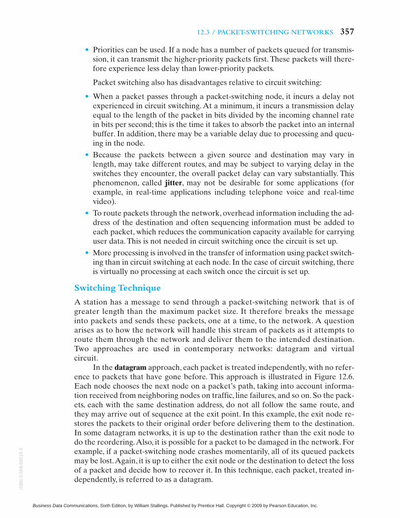
In the virtual circuit approach, a preplanned route is established before anypackets are sent. Once the route is established, all the packets between a pair ofcommunicating parties follow this same route through the network. This is illus-trated in Figure 12.7. Because the route is fixed for the duration of the logical
358 CHAPTER 12 / CIRCUIT SWITCHING AND PACKET SWITCHING
Figure 12.7 Packet Switching: Virtual-Circuit Approach
(c)
(b)
(a)
(d)
(e)
2 13
3
21
32
1
3 2 1
32
1
Business Data Communications, Sixth Edition, by William Stallings. Published by Prentice Hall. Copyright © 2009 by Pearson Education, Inc.
ISB
N0-558-69515-9

12.4 / TRADITIONAL WIDE AREA NETWORK ALTERNATIVES 359
connection, it is somewhat similar to a circuit in a circuit-switching network and isreferred to as a virtual circuit. Each packet now contains a virtual circuit identifieras well as data. Each node on the preestablished route knows where to direct suchpackets; no routing decisions are required. At any time, each station can have morethan one virtual circuit to any other station and can have virtual circuits to morethan one station.
So the main characteristic of the virtual-circuit technique is that a route be-tween stations is set up prior to data transfer. Note that this does not mean that thisis a dedicated path, as in circuit switching.A packet is still buffered at each node andqueued for output over a line. The difference from the datagram approach is that,with virtual circuits, the node need not make a routing decision for each packet. It ismade only once for all packets using that virtual circuit.
If two stations wish to exchange data over an extended period of time, there arecertain advantages to virtual circuits. First, the network may provide services relatedto the virtual circuit, including sequencing and error control. Sequencing refers to thefact that, because all packets follow the same route, they arrive in the original order.Error control is a service that assures not only that packets arrive in proper sequencebut also that all packets arrive correctly. For example, if a packet in a sequence fromnode 4 to node 6 fails to arrive at node 6, or arrives with an error, node 6 can requesta retransmission of that packet from node 4.Another advantage is that packets shouldtransit the network more rapidly with a virtual circuit; it is not necessary to make arouting decision for each packet at each node.
One advantage of the datagram approach is that the call setup phase isavoided. Thus, if a station wishes to send only one or a few packets, datagram de-livery will be quicker. Another advantage of the datagram service is that, becauseit is more primitive, it is more flexible. For example, if congestion develops in onepart of the network, incoming datagrams can be routed away from the conges-tion. With the use of virtual circuits, packets follow a predefined route, and thus itis more difficult for the network to adapt to congestion. A third advantage is thatdatagram delivery is inherently more reliable. With the use of virtual circuits, if anode fails, all virtual circuits that pass through that node are lost. With datagramdelivery, if a node fails, subsequent packets may find an alternate route that by-passes that node.
12.4 TRADITIONAL WIDE AREA NETWORK ALTERNATIVES
As Table 12.1 indicates, packet switching adds several new alternatives for widearea networking, in addition to those that can be provided using circuit-switchingtechnology. Just as there are public and private circuit-switching networks, thereare also public and private packet-switching networks. A public packet-switchingnetwork works much like a public telephone network. In this case, the networkprovides a packet transmission service to a variety of subscribers. Typically, thenetwork provider owns a set of packet-switching nodes and links these togetherwith leased lines provided by a carrier such as AT&T. Such a network is called avalue-added network (VAN), reflecting the fact that the network adds value tothe underlying transmission facilities. In a number of countries, there is a single
Business Data Communications, Sixth Edition, by William Stallings. Published by Prentice Hall. Copyright © 2009 by Pearson Education, Inc.
ISB
N0-
558-
6951
5-9

public network owned or controlled by the government and referred to as apublic data network (PDN). The other packet-switching alternative is a networkdedicated to the needs of a single organization. The organization may own thepacket-switching nodes or lease an entire dedicated packet-switching networkfrom a network provider. In either case, the links between nodes are again leasedtelecommunications lines.
Thus, a business is faced with an array of choices for meeting wide area net-working needs. These choices include a number of high-speed options, such asframe relay and ATM. In this section, we explore the various traditional WAN op-tions, to get some feel for the types of tradeoffs involved. The issues are revisited inChapter 13.
Before beginning our evaluation of these alternatives, it is useful to considerthe overview of circuit switching and packet switching provided in Table 12.2. Whileboth circuit switching and packet switching can be used for data transmission, eachhas its particular strengths and weaknesses for a given application.
360 CHAPTER 12 / CIRCUIT SWITCHING AND PACKET SWITCHING
Table 12.2 Relative Merits of Circuit Switching and Packet Switching of Data
Circuit Switching
Advantages Disadvantages
Compatible with voice. Economies of scale can be re-alized by using the same network for voice and data.
Commonality of calling procedures for voice anddata. No special user training or communication pro-tocols are needed to handle data traffic.
Predictable, constant rate for data traffic.
Subject to blocking. This makes it difficult to size thenetwork properly. The problem is less severe with theuse of dynamic nonhierarchical routing techniques.
Requires subscriber compatibility. The devices ateach end of a circuit must be compatible in terms ofprotocol and data rate, since the circuit is a transpar-ent connection.
Large processing and signal burden. For transaction-type applications, data calls are of short duration andneed to be set up rapidly. This proportionally in-creases the overhead burden on the network.
Packet Switching
Advantages Disadvantages
Provides speed conversion. Two attached deviceswith different data rates may exchange data; the net-work buffers the data and delivers them at the appro-priate data rate.
Appears nonblocking. As the network load increases,the delay increases, but new exchanges are usuallypermitted.
Efficient utilization. Switches and trunks are used ondemand rather than dedicating capacity to a particu-lar call.
Logical multiplexing. A host system can have simulta-neous conversations with a number of terminals overa single line.
Complex routing and control. To achieve efficiencyand resilience, a packet-switched network must em-ploy a complex set of routing and control algorithms.
Delay. Delay is a function of load. It can be long andit is variable.
Business Data Communications, Sixth Edition, by William Stallings. Published by Prentice Hall. Copyright © 2009 by Pearson Education, Inc.
ISB
N0-558-69515-9

12.4 / TRADITIONAL WIDE AREA NETWORK ALTERNATIVES 361
Wide Area Networks for Voice
Traditionally, the preferred business alternatives for wide area voice communica-tions all employ circuit switching. With the increasing competition and advancingtechnology of recent years, this still leaves the manager with many choices, includingprivate networks, software-defined networks, ordinary telephone service, and a vari-ety of special services such as toll-free numbers. Further complicating the choice isthe introduction of services related to ISDN.
With all of these choices, and with the constantly changing prices attached tothe various choices, it is difficult to generalize. What can be said is that business re-lies heavily on the public telephone networks and related services. Private networksare appropriate for an organization with a number of sites and with a substantialamount of voice traffic between them.
A new entry in the competition is voice over IP (VoIP), mentioned in Chapter 6.VoIP uses a packet transmission approach over Internets and intranets. VoIP is en-joying gradually growing acceptance as an alternative.
Wide Area Networks for Data
For data traffic, the number of wide area networking choices is even broader.Roughly, we can list the following categories as alternatives:
• Public packet-switching networks: There are a number of such networks in theUnited States and at least one in most industrialized countries. Typically, theuser must lease a line from the user’s computing equipment to the nearestpacket-switching node.
• Private packet-switching networks: In this case, the user owns or leases thepacket-switching nodes, which are generally collocated with the user’s dataprocessing equipment. Leased lines, typically 56 or 64 kbps digital lines, inter-connect the nodes.
• Private leased lines: Dedicated lines can be used between sites. No switching isinvolved, so a leased line is needed between any pair of sites that wish to ex-change data.
• Public circuit-switching networks: With the use of modems or switched digitalservice, the user can employ dial-up telephone lines for data communications.
• Private circuit-switching networks: If the user has an interconnected set of dig-ital PBXs, either by leased 56-kbps lines or T-1 lines, then this network cancarry data as well as voice.
• ISDN: ISDN offers both packet switching and traditional circuit switching inan integrated service.
The last two alternatives are likely to be justified on the basis of the voice traf-fic, with data traffic being a sort of bonus that comes with the network. Because thisapproach is therefore not directly comparable to the others, we do not consider itfurther in this chapter
As with voice, the choice of approach for data networking is complex and de-pends on current prices. In comparing the alternatives for wide area data networks,we look first at the cost and performance considerations, which are more easily
Business Data Communications, Sixth Edition, by William Stallings. Published by Prentice Hall. Copyright © 2009 by Pearson Education, Inc.
ISB
N0-
558-
6951
5-9

quantified and analyzed.Then we consider some other issues that are also importantin selecting a network.
COST/PERFORMANCE CONSIDERATIONS Data communications traffic can be roughlyclassified into two categories: stream and bursty. Stream traffic is characterized bylengthy and fairly continuous transmission. Examples are file transfer, telemetry,other sorts of batch data processing applications, and digitized voice communication.Bursty traffic is characterized by short, sporadic transmissions. Interactive client/servertraffic, such as transaction processing, data entry, and time sharing, fits this description.Facsimile transmission is also bursty.
The public circuit-switching network approach makes use of dial-up lines. Thecost is based on data rate, connection time, and distance. As we have said, this isquite inefficient for bursty traffic. However, for occasional stream-oriented require-ments, this may be the most appropriate choice. For example, a corporation mayhave distributed offices. At the close of the day, each office transfers a file to head-quarters summarizing the activities for that day. A dial-up line used for the singletransfer from each office appears to be the most cost-effective solution. When thereis a high volume of stream traffic among a few sites, the most economical solution isto obtain dedicated circuits among sites.These circuits, also known as leased lines orsemipermanent circuits, may be leased from a telecommunications provider, such asa telephone company, or from a satellite provider. The dedicated circuit carries aconstant fixed cost based on data rate and, in some cases, distance. If the traffic vol-ume is high enough, then the utilization will be high enough to make this approachthe most attractive.
On the other hand, if the traffic is primarily bursty, then packet switching hasthe advantage. Furthermore, packet switching permits terminals and computer portsof various data rates to be interconnected. If the traffic is primarily bursty but is ofrelatively modest volume for an organization, a public packet-switching networkprovides the best solution. In this case, the network provides a packet transmissionservice to a variety of subscribers, each of which has moderate traffic requirements.If there is a number of different subscribers, the total traffic should be great enoughto result in high utilization. Hence, the public network is cost effective from theprovider’s point of view. The subscriber gets the advantages of packet switchingwithout the fixed cost of implementing and maintaining the network.The cost to thesubscriber is based on both connection time and traffic volume but not distance.
If the volume of an organization’s bursty traffic is high and is concentratedamong a small number of sites, a private packet-switching network is the best solu-tion. With a lot of bursty traffic among sites, the private packet-switching networkprovides much better utilization and hence lower cost than using circuit switching orsimple dedicated lines. The cost of a private network (other than the initial fixedcost of the packet switching nodes and the dedicated lines) is based solely on dis-tance.Thus, it combines the efficiencies of public packet switching with the time andvolume independence of dedicated circuits.
OTHER CONSIDERATIONS In addition to the issues of cost and performance, thechoice of network should also take into account control, reliability, and security.
An organization large enough to need a wide area data network will come torely heavily on that network. Accordingly, it is vital that management be able to
362 CHAPTER 12 / CIRCUIT SWITCHING AND PACKET SWITCHING
Business Data Communications, Sixth Edition, by William Stallings. Published by Prentice Hall. Copyright © 2009 by Pearson Education, Inc.
ISB
N0-558-69515-9

12.4 / TRADITIONAL WIDE AREA NETWORK ALTERNATIVES 363
maintain proper control of the network to provide an efficient and effective serviceto users. We will explore this topic at some length in Chapter 19. For our purposeshere, we can say that three aspects of control are significant in comparing variousnetwork approaches: strategic control, growth control, and day-to-day operation ofthe network.
Strategic control involves the process of designing and implementing thenetwork to meet the organization’s unique requirements. With public packetswitching, the subscriber has virtually no strategic control over service levels, re-liability, or maintenance. The network is intended as a public utility to serve theaverage customer. With either dedicated lines or a private packet-switching net-work, the user organization can decide on the capacity and level of redundancythat it is willing to pay for. Growth control allows users to plan for network ex-pansion and modifications arising as their needs change. A private packet-switchingnetwork provides the most flexibility in accommodating needs for growth. Addi-tional packet switching nodes, more trunks, and higher-capacity trunks can beadded as needed. These raise the overall capacity and reliability of the network.Although the user has control over the number and capacity of lines in a dedi-cated-line design, there is less flexibility for incrementally expanding the net-work. Again, with a public packet-switching network, the user has no control overgrowth. The user’s needs are satisfied only if they happen to be within the capa-bilities of the public network. With respect to day-to-day operation, the user isconcerned with accommodating peaks of traffic and with quickly diagnosing andrepairing faults. Packet-switching networks can be designed with effective cen-tralized network control that allows the network to be adjusted to changing con-ditions. Of course, in the case of the public network, the user is dependent on thenetwork provider. As in any public utility, such as a transportation system, theretend to be “rush hours” in public networks when service levels decline. Day-to-day control is more difficult to automate in the case of dedicated lines; availabletools are comparatively few and crude because we are not dealing with a unifiednetwork.
The inherent reliability of a packet-switching network is higher than that of acollection of dedicated lines. The network consists of a set of shared facilities and isequipped with centralized, automated network control facilities. Faults can be easilylocated and isolated and the traffic shifted to the healthy part of the network. Apublic network may be able to afford a greater investment in redundancy and con-trol tools, because the cost is spread over many users. Further, the user is relieved ofthe burden of developing the expertise required to keep a large data communica-tions network operational.
Finally, data security is vital to most corporations. We explore this topic in de-tail in Chapter 18. For purposes of the present discussion, we can say that use of aprivate network or dedicated lines will clearly afford greater security than a publicpacket-switching network. Public networks can use various access control mecha-nisms to limit the ways in which users can obtain data across the network. Thosesame control mechanisms are useful in private networks, because an organizationmay wish to segregate various communities of users.
Table 12.3 summarizes the difference among the various communicationsapproaches.
Business Data Communications, Sixth Edition, by William Stallings. Published by Prentice Hall. Copyright © 2009 by Pearson Education, Inc.
ISB
N0-
558-
6951
5-9

364 CHAPTER 12 / CIRCUIT SWITCHING AND PACKET SWITCHING
Table 12.3 Features of Wide Area Networks
Feature Dedicated (leased lines)
Public Packet Private Packet
Strategic control Network design, service,and maintenance can begiven priority and con-trolled by user.
Service limited to thatwhich suits average cus-tomer.
Network design, service,and maintenance can begiven priority and con-trolled by user.
Growth control and op-eration control
Not integrated; decen-tralized fault detectionmay be expensive.
Provided by service sup-plier to satisfy averagerequirements.
Integrated into allequipment; centralizedfault isolation and detec-tion.
Reliability Manual and user-visiblerecovery from failure.
Transparent and auto-matic recovery from failure.
Transparent and auto-matic recovery from failure.
Security Private users only. Public users, network ac-cess control.
Private users only, net-work access control.
APPLICATION NOTE
Switching
Discussions about switching can be confusing because there are so many protocols, differ-ent possible layers of networking models, and different types of switches. For many orga-nizations, the type of switching used to send data from the local site to externaldestinations can be a complete mystery due to the complexity of wide area networks anda reduced level of local control. Once the data leave the home network, there may be lit-tle that a local network administrator can do to affect its travel. Usually the influence ofthe local network staff is limited to the customer premises equipment and the type of con-nection going offsite.
To make things more difficult, next generation networks will make use of multilayerswitching techniques such as layer 3 switching (layer 2 routing), optical switching, and ap-plication layer switching. In the next couple of paragraphs we will try to provide someguidance into the switching terms that a typical network administrator is likely to run intoand some of the terms used to describe external connectivity.
Almost all local area networks run the Internet Protocol (IP) over some form of Ether-net. Ethernet nodes are usually connected to each other via a layer 2 switch that examineslayer 2 addresses in the frame prior to forwarding. The traffic encapsulated within theEthernet frame is the IP-based data. The IP packet header includes all the informationnecessary for getting the packet from source to destination. This means that we are usinga datagram approach.While upper-layer protocols like the Transmission Control Protocol(TCP) can control the flow of data to a certain extent, they do not change the type ofswitching/routing used. If we include the idea that any routers involved are processing theIP packets flowing between networks, we could classify this type of transmission as apacket-switching network with a datagram approach. Alternately, we might say that weused Ethernet switching and IP-based routers (packet switches) to move the traffic along.Both packet switching and its counterpart, circuit switching, are described in this chapter.
Business Data Communications, Sixth Edition, by William Stallings. Published by Prentice Hall. Copyright © 2009 by Pearson Education, Inc.
ISB
N0-558-69515-9

12.4 / TRADITIONAL WIDE AREA NETWORK ALTERNATIVES 365
When traffic must travel offsite, it will be transferred to the network of the Internet ser-vice provider (ISP) for processing. Essentially, this is the beginning of the Internet. TheInternet is actually a huge collection of networks. Web sites or Web servers are also at-tached to these networks. The ISP networks can vary quite a bit in terms of protocolsused, speeds available, and the type of switching when compared to the local area net-works of their customers. One consistent item is that all networks attached to the Internettransmit and receive IP packets. As a packet travels from source to destination, it willlikely cross several different network types before arriving.
Upon entering the ISP network, routing decisions must be made. If the network utilizes adatagram approach, no further action is taken as the IP packets contain all of the neces-sary information and no circuit is required. However, if the network utilizes virtual cir-cuits for establishing a pathway from one end of the ISP network to the other, this circuitmust be established before any data can be forwarded. Examples of protocols utilizingvirtual circuits are frame relay and asynchronous transfer mode, (ATM). Note that Ether-net rarely survives past the customer connection to the Internet.
Once the circuit has been established, the data are forwarded, with each network nodemaking forwarding decisions based on the connection setup.Thus, a routing decision (typ-ically layer 3) is made upon entrance to the network and then lower-layer switching deci-sions are made as the data cross the network.This virtual circuit is only valid to the borderof the provider’s network. All packets heading for the same destination follow the samepath.At the edge, another routing decision must be made and a hand-off completed to thefollowing network. At this point, the process starts again for each network until the desti-nation is reached. The primary reason we process traffic in this fashion is for an improve-ment in speed. The advantage is that we do not have to process layer 3 IP addresses forthe packets. Switching data at layer 2 is almost always faster than routing data at layer 3,no matter what kind of network you are on. Since these virtual circuit connections have asetup and teardown procedure and the circuit is allocated to that connection, this type offorwarding is called circuit switching.
In another example of circuit switching, a dial-up user initially connects to an ISP with atelephone call from a modem and the data are handled in the exact same fashion—circuitswitching. The only difference is that instead of voice, the data started out as digital fromthe computer. Once the circuit-switched telephone call to the ISP is made, data can betransferred. The packets all follow the same path to the ISP. Internally, the ISP will have astandard IP network running over Ethernet that simply forwards the data to the correctrouter output interface. This interface may subsequently be connected to another, largerISP using T carriers, a frame relay or an ATM network—but they all will carry IP packetsas their payload.The packet passes through a router and is forwarded to the next networklink. Note that at no time are the contents of the layer 3 IP datagrams manipulated. Theyare simply being carried over a different layer 2 network.
The term switching has many meanings, but all of them usually refer to the process of for-warding traffic between locations. The type of external switching that an organization se-lects is a decision that is often dependent upon factors such as bandwidth requirements,cost, and availability. There are a large number of protocols that can be used for connect-ing to the outside world, but choosing the correct type requires a survey of available prod-ucts and an understanding of local requirements.
Business Data Communications, Sixth Edition, by William Stallings. Published by Prentice Hall. Copyright © 2009 by Pearson Education, Inc.
ISB
N0-
558-
6951
5-9

12.5 SUMMARY
The use of a direct point-to-point link for information communications is impractical forall but the most limited requirements. For cost-effective, practical information commu-nications, some sort of communications network is needed. For communications outsidethe range of a single building or a cluster of buildings, a wide area network (WAN) isemployed.Two basic technologies are employed: circuit switching and packet switching.
Circuit switching is used in public telephone networks and is the basis for privatenetworks built on leased lines and using on-site circuit switches. Circuit switchingwas developed to handle voice traffic but can also handle digital data, although thislatter use is often inefficient. With circuit switching, a dedicated path is establishedbetween two stations for communication. Switching and transmission resourceswithin the network are reserved for the exclusive use of the circuit for the durationof the connection.The connection is transparent: Once it is established, it appears toattached devices as if there were a direct connection.
Packet switching is employed to provide an efficient means of using the sharedfacilities in a data communications network. With packet switching, a station trans-mits data in small blocks, called packets. Each packet contains some portion of theuser data plus control information needed for proper functioning of the network.Public packet-switching networks are available, to be shared by a number of sepa-rate subscriber communities. The technology may also be employed to build a pri-vate packet-switching network.
The choice between circuit and packet switching depends on a host of considera-tions, including cost, performance, reliability, and flexibility. Both technologies willcontinue to be important in wide area networking.
12.6 RECOMMENDED READING AND WEB SITES
As befits its age, circuit switching has inspired a voluminous literature. Two goodbooks on the subject are [BELL00] and [FREE04].
The literature on packet switching is also enormous. Books with good treatments ofthis subject include [SPOH02] and [BERT92]. [ROBE78] is a classic paper on howpacket switching technology evolved. [BARA02] and [HEGG84] are also interesting.
366 CHAPTER 12 / CIRCUIT SWITCHING AND PACKET SWITCHING
BARA02 Baran, P. “The Beginnings of Packet Switching: Some Underlying Concepts.”IEEE Communications Magazine, July 2002.
BELL00 Bellamy, J. Digital Telephony. New York: Wiley, 2000.BERT92 Bertsekas, D., and Gallager, R. Data Networks. Englewood Cliffs, NJ: Prentice
Hall, 1992.FREE04 Freeman, R. Telecommunication System Engineering. New York: Wiley, 2004.HEGG84 Heggestad, H. “An Overview of Packet Switching Communications.” IEEE
Communications Magazine, April 1984.ROBE78 Roberts, L. “The Evolution of Packet Switching.” Proceedings of the IEEE,
November 1978.SPOH02 Spohn, D. Data Network Design. New York: McGraw-Hill, 2002.
Business Data Communications, Sixth Edition, by William Stallings. Published by Prentice Hall. Copyright © 2009 by Pearson Education, Inc.
ISB
N0-558-69515-9
12.7 / KEY TERMS, REVIEW QUESTIONS,AND PROBLEMS 367
Review Questions
12.1 Why is it useful to have more than one possible path through a network for each pairof stations?
12.2 Concerning a switched communications network, answer the following as either trueor false.a. All switching nodes are connected to every other node.b. Links between switching nodes utilize some sort of multiplexing technique.c. Switching nodes provide connectivity for a single end station.
12.3 What are the four generic architectural components of a public communications net-work? Define each term.
12.4 Answer the following as either true or false regarding circuit switching.a. A complete connection from end to end must be completed before data transmis-
sion can occur.b. There are three basic stages; connection setup, data transfer, and connection ter-
mination.c. Circuit switching is very efficient.
12.5 What is the principal application that has driven the design of circuit-switching net-works?
12.6 Distinguish between static and alternate routing in a circuit-switching network.12.7 What is the difference between inchannel and common channel signaling?12.8 The control signals used in the public switched telephone network are part of what ar-
chitecture?12.9 Explain the difference between datagram and virtual circuit operation.
12.10 What are some advantages of private networks?
Recommended Web sites:
• IP Multimedia Subsystems Forum: News, technical information, and vendor informa-tion on Voice over IP and softswitch technology and products
12.7 KEY TERMS, REVIEW QUESTIONS,AND PROBLEMS
Key Terms
circuit switchingcommon channel signalingcontrol signalingdatagramexchangeinchannel signalingintegrated services digital
network (ISDN)
local looppacketpacket switchingpublic data network (PDN)softswitchsubscribersubscriber linesubscriber loop
trunkvalue-added network (VAN)virtual circuit
Business Data Communications, Sixth Edition, by William Stallings. Published by Prentice Hall. Copyright © 2009 by Pearson Education, Inc.
ISB
N0-
558-
6951
5-9

368 CHAPTER 12 / CIRCUIT SWITCHING AND PACKET SWITCHING
12.11 What are some of the limitations of using a circuit-switching network for data trans-mission?
12.12 What is a value-added network (VAN)?12.13 Why is packet switching impractical for digital voice transmission?
Problems
12.1 How far away from your local switching center is your business or home?12.2 In the public switched telephone network, your call is set up and switched based on
the numbers that you dial. These numbers actually provide different frequencysounds or tones to the switching center. What is this signaling called?
12.3 Define the following parameters for a switching network:N � number of hops between two given end systemsL � message length in bitsB � data rate, in bits per second (bps), on all linksP � fixed packet size, in bitsH � overhead (header) bits per packetS � call setup time (circuit switching or virtual circuit) in secondsD � propagation delay per hop in secondsa. For N � 4, L � 3200, B � 9600, P � 1024, H � 16, S � 0.2, D � 0.001, compute the
end-to-end delay for circuit switching, virtual circuit packet switching, and data-gram packet switching. Assume that there are no acknowledgments. Ignore pro-cessing delay at the nodes.
b. Derive general expressions for the three techniques of part (a), taken two at a time(three expressions in all), showing the conditions under which the delays are equal.
12.4 Consider a simple telephone network consisting of two end offices and one interme-diate switch with a 1-MHz full-duplex trunk between each end office and the interme-diate switch. The average telephone is used to make four calls per 8-hour workday,with a mean call duration of six minutes. Ten percent of the calls are long distance.What is the maximum number of telephones an end office can support?
12.5 Explain the flaw in the following reasoning: Packet switching requires control andaddress bits to be added to each packet. This introduces considerable overhead inpacket switching. In circuit switching, a transparent circuit is established. No extra bitsare needed.a. Therefore, there is no overhead in circuit switching.b. Because there is no overhead in circuit switching, line utilization must be more ef-
ficient than in packet switching.12.6 Assuming no malfunction in any of the stations or nodes of a network, is it possible
for a packet to be delivered to the wrong destination?12.7 Consider a packet-switching network of N nodes, connected by the following topologies:
a. Star: One central node with no attached station; all other nodes attach to the cen-tral node.
b. Loop: Each node connects to two other nodes to form a closed loop.c. Fully connected: Each node is directly connected to all other nodes.
For each case, give the average number of hops between stations.
Business Data Communications, Sixth Edition, by William Stallings. Published by Prentice Hall. Copyright © 2009 by Pearson Education, Inc.
ISB
N0-558-69515-9
Related Documents