11.1-1 Chapter 11 Properties of Walls Using Lightweight Concrete and Lightweight Concrete Masonry Units 11.0 Introduction 11.1 Thermal Resistance and Energy Conservation 11.2 Fire Resistance 11.3 Acoustical Resistance 11.4 Enclosure Properties April 2007 Expanded Shale, Clay & Slate Institute (ESCSI) 2225 E. Murray Holladay Rd, Suite 102 Salt Lake City, Utah 84117 (801) 272-7070 Fax: (801) 272-3377 [email protected] www.escsi.org

Welcome message from author
This document is posted to help you gain knowledge. Please leave a comment to let me know what you think about it! Share it to your friends and learn new things together.
Transcript

11.1-1
Chapter 11
Properties of Walls Using
Lightweight Concrete and
Lightweight Concrete Masonry Units
11.0 Introduction
11.1 Thermal Resistance and Energy Conservation
11.2 Fire Resistance
11.3 Acoustical Resistance
11.4 Enclosure Properties
April 2007
Expanded Shale, Clay & Slate Institute (ESCSI)
2225 E. Murray Holladay Rd, Suite 102
Salt Lake City, Utah 84117
(801) 272-7070 Fax: (801) 272-3377
[email protected] www.escsi.org

7/11/2007
11.1-2
Chapter 11
11.0 Introduction
11.1 Thermal Resistance and Energy Conservation with Structural Lightweight
Concrete and Lightweight Concrete Masonry
Thermal Conductivity
Thermal Conductivity of Aggregates and Natural Minerals
Influence of Moisture
Thermal Conductivity of Concrete Used in Concrete Masonry Units
Thermal Conductivity Calculations Using the Cubic Model
Practical Thermal Conductivity
Thermal Resistance of Concrete Masonry Units
Calculation Methods for Steady-State Thermal Resistance of Wall
Systems
Maximum “R” Values That Can Be Achieved With Insulated CMU’s
Thermal Resistance of Other Concrete Wall Systems
Thermal Inertia, thermal mass
Thermal diffusivity
Heat Capacity
Insulation
Daily Temperature Changes
Building Design
Calibrated Hot-Box Facilities
Computer Simulations of Buildings
Interior Thermal Mass
Thermal Properties for Passive Solar Design
Incorporating Mass into Passive Solar Designs
Summary
Condensation Control
Prevention of Condensation on Wall Surfaces Under Steady-State
Analysis
Prevention of Condensation Within Wall Constructions
Appendix 11.1A ESCSI Information Sheet No. 4 “Thermal Insulation”, Reprinted 6/83
Appendix 11.1B Thermal Inertia of Lightweight Concrete Products
Appendix 11.1C ESCSI Information Sheet 3201 “Energy Efficient Buildings with
SmartWall Systems®”, 4th
Edition, Aug. 2004.
Appendix 11.1D ESCSI Information Sheet 3530, “Life Cycle Cost Analysis”, Mar. 2000.

7/11/2007
11.1-3
11.2 Fire Resistance of Lightweight Concrete and Masonry
Definitions of Terms
Fire Endurance
Fire Resistance
Fire Rating
Standard Fire Test
End-Point Criteria and Analytical Methods
Walls
Beams
Floors and Roofs
Columns
Factors Influencing Endurance of Concrete and Masonry Units
Effect of Structural Slab Thickness, Concrete Density and Aggregate Type
on Fire Endurance
Effect of Restraint on Member During Fire Loading
Temperature Distribution Within Concrete and Masonry members and
Assemblies
Heat Transmission End Point
Solid Concrete Walls, Floors, and Roofs
Performance of Lightweight Concrete Slabs in Actual Fires
Tapered Flanges
Ribbed Concrete Members
Hollow-Core Concrete Planks
Structural End Point
Fire Resistance of Prestressed Concrete Floor Slab
Thermal Expansion During Fires
Multi-Wythe Walls
Fire Resistance of Concrete Masonry Walls
Analysis of the Validity of the Fire Resistance Rating Contained in Table
6.
Field Performance of Lightweight Concrete Masonry Units
Safety
Appendix 11.2A Underwriters Lab Report of ESCSI ET’s for 2, 3, and 4 hours
Appendix 11.2B Underwriters Lab UL 618
Appendix 11.2C Fire Resistance Ratings, Including “Estimated Ratings”
Appendix 11.2D School will probably open despite fire

7/11/2007
11.1-4
11.3 Acoustical Resistance of Walls of Lightweight Concrete and Lightweight
Concrete Masonry
Resistance to Transmission of Airborne Sound
Introduction
The Energy of Sound
Sound Transmission Resistance of Concrete Masonry
Determination of Sound Transmission Class (STC)
Calculated STC Values
Sound Transmission Resistance of Structural Lightweight Concrete
Sound Absorption of Concrete Masonry Walls
Introduction
Principal of Control
Absorption Control
Texture
Reverberation
Sound Absorption Calculations
Resistance to Impact Sound
Introduction
Laboratory Testing Program
11.4 Resistance to the Environment of Lightweight Concrete and Lightweight
Concrete Masonry
Dimension Stability
General
Thermal Movements in Masonry
Reduce Thermal Movements
Impact Resistance of Lightweight Concrete Masonry Walls
Air Barrier Resistance
Code Requirements
Air Impermeability
Appendix 11.4A Impact Performance of Fully Grouted Concrete Masonry Walls
7/11/2007
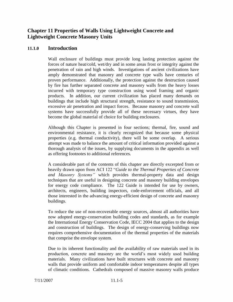
11.1-5
Chapter 11 Properties of Walls Using Lightweight Concrete and
Lightweight Concrete Masonry Units
11.1.0 Introduction
Wall enclosure of buildings must provide long lasting protection against the
forces of nature heat/cold, wet/dry and in some areas frost or integrity against the
penetration of rain and high winds. Investigations of ancient civilizations have
amply demonstrated that masonry and concrete type walls have centuries of
proven performance. Additionally, the protection against the destruction caused
by fire has further separated concrete and masonry walls from the heavy losses
incurred with temporary type construction using wood framing and organic
products. In addition, our current civilization has placed many demands on
buildings that include high structural strength, resistance to sound transmission,
excessive air penetration and impact forces. Because masonry and concrete wall
systems have successfully provide all of these necessary virtues, they have
become the global material of choice for building enclosures.
Although this Chapter is presented in four sections; thermal, fire, sound and
environmental resistance, it is clearly recognized that because some physical
properties (e.g. thermal conductivity), there will be some overlap. A serious
attempt was made to balance the amount of critical information provided against a
thorough analysis of the issues, by supplying documents in the appendix as well
as offering footnotes to additional references.
A considerable part of the contents of this chapter are directly excerpted from or
heavily drawn upon from ACI 122 “Guide to the Thermal Properties of Concrete
and Masonry Systems” which provides thermal-property data and design
techniques that are useful in designing concrete and masonry building envelopes
for energy code compliance. The 122 Guide is intended for use by owners,
architects, engineers, building inspectors, code-enforcement officials, and all
those interested in the advancing energy-efficient design of concrete and masonry
buildings.
To reduce the use of non-recoverable energy sources, almost all authorities have
now adopted energy-conservation building codes and standards, as for example
the International Energy Conservation Code, IECC 2004 that applies to the design
and construction of buildings. The design of energy-conserving buildings now
requires comprehensive documentation of the thermal properties of the materials
that comprise the envelope system.
Due to its inherent functionality and the availability of raw materials used in its
production, concrete and masonry are the world’s most widely used building
materials. Many civilizations have built structures with concrete and masonry
walls that provide uniform and comfortable indoor temperatures despite all types
of climatic conditions. Cathedrals composed of massive masonry walls produce

7/11/2007
11.1-6
an indoor climate with little temperature variation during the entire year despite
the absence of a heating system. Even primitive housing in the desert areas of
North America used thick masonry walls that produced acceptable interior
temperatures despite outside temperatures that had a high daily peak.
Exterior wall systems made with concrete products provide efficient load-bearing
masonry wall systems as well as resistance to weather, temperature changes, fire,
and noise. Many of these wall systems are made with lightweight concrete to
enhance thermal characteristics, static and dynamic resistance.
In addition to structural requirements, a building envelope should be designed to
control the flow of air, heat, sunlight, radiant energy, and water vapor, and to
avoid the entry of rain and snow. It should also provide the many other attributes
generally associated with enclosure materials, including fire and noise control,
structural adequacy, durability, aesthetic quality, and economy. Any analysis of
building enclosure materials should account for their multifunctional purpose.
11.1.1 Thermal Resistance and Energy Conservation with Structural
Lightweight Concrete and Lightweight Concrete Masonry
Thermal Conductivity
Thermal conductivity is a specific property of a gas, liquid, or solid. The
coefficient of thermal conductivity k is a measure of the rate at which heat
(energy) passes perpendicularly through a unit area of homogeneous material of
unit thickness for a temperature difference of one degree; k is expressed as Btu •
in./(h • ft² • ºF)[W/(m²K)].
The thermal resistance of a layer of material can be calculated as the thickness of
the layer divided by the thermal conductivity of the material. If a wall is made up
of uniform layers of different materials in contact with each other, or separated by
continuous air spaces of uniform thickness, the resistances of each are combined
by a simple addition. Surface-air-film resistances should be included to yield the
wall’s total thermal resistance (R-value). If any air spaces are present between
layers, the thermal resistances of these air spaces are also included.
The thermal conductivity of a material, such as concrete or insulation, is usually
determined by measuring in accordance with ASTM C 177 or ASTM C 236.
Several methods for calculating concrete thermal conductivity have been
developed and are discussed. These calculated estimates are useful if test data are
not available.
Basic testing programs conducted by Technical Institutions demonstrate that, in
general, the coefficient of thermal conductivity for concrete kc, is dependent on
the aggregate types used in the concrete mixture. For simplicity, these data are
often correlated to concrete density d. Valore (1980) plotted oven-dry density of

7/11/2007
11.1-7
concrete as a function of the logarithm of kc, developing a straight line that can be
expressed by the equation
kc = 0.5e0.02d
(inch-pound units)
(11-1)
kc = 0.072e0.00125d
(S.I. units)
where d = oven-dry density in lb/ft³ [kg/m³].
Thermal conductivity values for concretes with the same density made with
different aggregates can differ from the relationship expressed by Eq. (11-1) and
may significantly underestimate kc for normalweight concretes and for lightweight
concretes containing normalweight supplemental aggregates (Valore 1980, 1988).
This is due to differences in the thermal properties of specific mineral types in the
aggregates. Thermal conductivity values obtained using Eq. (11-1) for concrete
with densities from 20 lb/ft³ to 100 lb/ft³ [320 to 1600 kg/m³] correlate better to
test data than for concretes outside this density range (Valore 1980).
Thermal Conductivity of Natural Minerals and Aggregates
Oven-dry thermal-conductivity values for natural minerals and aggregates are
shown in Table 11.1.1.
Table 11.1.1 – Thermal Conductivity of some natural minerals
Mineral Thermal Conductivity
Quartz (single crystal) 87, 47
Quartz 40
Quartzite 22 to 37
Hornblende-quartz-gneiss 20
Quartz-monzonite 18
Sandstone 9 to 16
Granite 13 to 28
Marble 14 to 21
Limestone 6 to 22
Chalk 6
Diorite (dolerite) 15.6
Basalt (trap rock) 9.6 to 15
Slate 13.6
Lightweight Aggregate 3.3*
*From “Thermo-Structural Stability of Concrete Masonry Walls”, Holm &
Bremner 1987

7/11/2007
11.1-8
Influence of Moisture
In normal use, concrete is not in moisture-free or oven-dry conditions; thus,
concrete conductivity should be corrected for moisture effects.
A more accurate value to determine moisture effects may be estimated by
increasing the value of kc by 6% for each 1% of moisture by weight (Valore 1980,
1988).
(11-2)
where dm and do are densities of concrete in
moist and oven-dry conditions, respectively.
For most concrete walls, a single factor of 1.2 can be applied to oven-dry kc
values (Valore 1980). It then becomes necessary only to change the constant in
Eq. (11-2) from 0.5 [0.072] to 0.6 [0.0865] to provide for a 20% increase in kc for
air-dry, in-service, concrete, or concrete masonry:
kc = 0.6 • e0.02d
(inch-pound units)
(11-3)
kc = 0.0865 • e0.00125d
(S.I. units)
Thermal Conductivity of Concrete Used in Concrete Masonry Units
Concrete Masonry Units (CMU) consists of approximately 65 to 70% aggregate
by volume. The remaining volume consists of voids between aggregate particles,
entrapped air, and cement paste. The typical air-void content of concrete used to
make lightweight CMU’s, for example, has been found to be about 8-12% by
volume. Expressed as a percentage of the cement paste, void volumes are
approximately 25 to 40%. For a typical lightweight CMU having a net w/c of 0.6
and an average cement-paste air-void content of 40%, the thermal conductivity
would be in the range of 1.5 to 1.8 Btu • in./h • ft² • ºF [0.22 to 0.26 W/(m²K)].
Such values are considerably lower than those in Eq. (11-1) or Eq. (11-2) for
typical lightweight aggregate, concrete (void-free) (Valore 1980) because the air
spaces found in the zero slump CMU lightweight concrete provide additional heat
flow resistance, thus lowering the conductivity.
o
omcc
d
dd6(1k)corrected(k

7/11/2007
11.1-9
Thermal Conductivity Calculations Using the Cubic Model
The cubic model can be used to calculate kc as a function of cement paste
conductivity, aggregate conductivity, and aggregate volume. The cubic model
(Fig. 11.1.1) is a unit volume cube of concrete consisting of a cube of aggregate
of volume Va encased on all sides by a layer of cement past of unit thickness, (1 –
Va1/3
)/2. The cubic model also accounts for the fact that concrete is a thermally
and physically heterogeneous material and may contain highly conductive
aggregates that serve as thermal bridges or shunts. Thermal bridges are highly
conductive materials surrounded by relatively low conductive materials that
greatly increase the composite system’s conductivity. In the case of concrete,
highly conductive aggregates are the thermal bridges and they are surrounded by
the lower conductive cement paste and/or and fine aggregate matrix. To use the
cubic model, Eq. (11-4), thermal-conductivity values for cement paste kp,
aggregate ka, and aggregate volume Va are required for estimating the thermal
conductivity of concrete.
Figure 11.1.1 Cubic model for calculating thermal conductivity
kc of concrete as a function of conductive kp and ka of cement
paste and aggregate, and volume fraction Va of aggregate.

7/11/2007
11.1-10
When fine and coarse aggregate ka values differ, kc is calculated for the paste/fine
aggregate mortar first and the calculation is then repeated for the paste/coarse
aggregate combination using the appropriate Va value in each step. For concretes
weighing 120 lb/ft³ [1920 kg/m³] or less, thermal conductivities determined using
Eq. (11-2) show good agreement with the thermal conductivity determined using
the simpler conductivity/density relationship of Eq. (11-1). For normalweight
concretes with densities greater than 120 lb/ft³ [1920 kg/m³], Eq. (11-4), yields
more accurate kc values than Eq. (11-1).
The cubic model shows that the thermal conductivity of a discrete two-phase
system, such as concrete, can also be calculated by knowing the volume fractions
and the thermal conductivity values of the cement pastes and aggregates (Fig.
11.1). For lightweight aggregate concretes, Eq. (11-1) yields kc values similar to
those calculated by using the cubic-model equation, Eq. (11-4). Equation (11-1)
is not always accurate over a wide range of concrete densities (Valore 1980),
particularly above 100 lb/ft³ [1600 kg/m³], because aggregate mineralogical
characteristics cause a wide range of aggregate thermal conductivities. The cubic-
model equation is also appropriate for calculating thermal conductivities of
concrete above 100 lb/ft³ [1600 kg/m³]. The cubic-model equation demonstrates
how the factors that influence concrete thermal conductivity kc impose a ceiling
limit on kc even for concretes containing hypothetical aggregates with infinitely
high thermal conductivities. The insulative effect of the cement paste matrix on
kc is determined by its quantity and quality of the paste volume fraction and
density. The cubic model also explains how normalweight aggregates
produce disproportionately high conductivity values when added to
lightweight-aggregate concrete.
4)-(11
1 3/23/2
3/2
3/2
ap
aa
aaa
apc
Vk
Vk
VVV
Vkk

7/11/2007
11.1-11
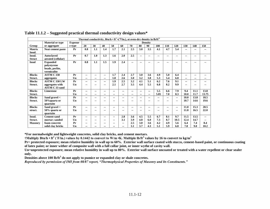
Practical Thermal Conductivity
Practical thermal conductivity design values for normalweight and lightweight
concrete, solid clay brick, cement mortar, and gypsum materials are shown in
Table 11.1.2, (ACI 122).
11.1-12
Table 11.1.2 – Suggested practical thermal conductivity design values*
*For normalweight and lightweight concretes, solid clay bricks, and cement mortars.
†Multiply Btu/h • ft2 (˚F/in.) values by 0.1442 to convert to W/m •K. Multiple lb/ft
3 values by 16 to convert to kg/m
3
Pr= protected exposure; mean relative humidity in wall up to 60%. Exterior wall surface coated with stucco, cement-based paint, or continuous coating
of latex paint; or inner wither of composite wall with a full collar joint, or inner wythe of cavity wall.
Un=unprotected exposure; mean relative humidity in wall up to 80%. Exterior wall surface uncoated or treated with a water repellent or clear sealer
only.
Densities above 100 lb/ft3 do not apply to pumice or expanded clay or shale concretes.
Reproduced by permission of IMI from 08/87 report, “Thermophysical Properties of Masonry and Its Constituents.”
Thermal conductivity, Btu/h • ft2 •( /in.), at oven-dry density in lb/ft3†
Group
Material or type
or aggregate
Exposur
e type
Density
20 30 40 50 60 70 80 90 100 110 120 130 140 150
Matrix
Insul.
Neat cement paste Pr 0.8 1.1 1.4 1.7 2.1 2.5 3.0 3.5 4.1 4.7 5.4 -- -- --
Insul.
Struct
Autoclaved
aerated (cellular)
Pr 0.7 1.0 1.3 1.6 2.0 2.5 -- -- -- -- -- -- -- --
Insul Expanded
polystyrene
beads, perlite,
vermiculite
Pr 0.8 1.1 1.5 1.9 2.4 -- -- -- -- -- -- -- -- --
Blocks
Struct.
ASTM C 330
aggregates
Pr
Un
--
--
--
--
--
--
1.7
1.8
2.4
2.6
2.7
3.0
3.0
3.2
3.6
3.8
4.9
5.3
5.0
5.4
6.4
6.8
--
--
--
--
--
--
Blocks
Struct.
ASTM C 330 LW
aggregates with
ASTM C 33 sand
Pr
Un
--
--
--
--
--
--
1.9
2.1
2.5
2.7
3.2
3.5
4.1
4.4
5.1
5.5
6.2
6.8
7.6
8.2
9.1
9.9
--
--
--
--
--
--
Blocks
Struct.
Limestone Pr
Un
--
--
--
--
--
--
--
--
--
--
--
--
--
--
--
--
5.5
5.85
6.6
7.0
7.9
8.3
9.4
10.0
11.1
11.7
13.8
13.75
Blocks
Struct.
Sand gravel <
50%quartz or
quartzite
Pr
Un
--
--
--
--
--
--
--
--
--
--
--
--
--
--
--
--
--
--
--
--
--
--
10.0
10.7
13.8
14.6
18.5
19.6
Blocks
struct.
Sand gravel >
50% quartz or
quartzite
Pr
Un
--
--
--
--
--
--
--
--
--
--
--
--
--
--
--
--
--
--
--
--
--
--
11.0
11.8
15.3
16.5
20.5
22.0
Insul.
Struct.
Masonry
Cement-sand
mortar; sanded
foam concrete
solid clay bricks
Pr
Un
Pr
Un
--
--
--
--
--
--
--
--
--
--
--
--
--
--
--
--
2.8
3.1
--
--
3.6
3.9
2.5
3.1
4.5
4.8
3.0
3.7
5.5
6.0
3.6
4.3
6.7
7.3
4.2
5.1
8.1
8.7
4.9
5.9
9.7
10.5
5.6
6.8
11.5
12.4
6.4
7.8
13.5
14.7
7.4
9.0
--
--
8.4
10.2

11.1-13
Thermal Resistance of Concrete Masonry Units
Thermal resistance of CMU’s is affected by many variables, including unit shape
and size, concrete density, insulation types, aggregate type(s), aggregate grading,
aggregate mineralogy, cementitious binder, and moisture content. It simply is not
feasible to test all of the possible variations. More than 100 CMU walls,
however, have been tested and reported on by Valore 1980. These tests provide a
basis for comparison of various calculation methods. Two calculation methods
have been widely used and accepted: the parallel-path method and the series-
parallel method (also know as isothermal planes). Both methods are described in
the following paragraphs.
The parallel-path method was considered acceptable practice until insulated
CMU’s appeared in the marketplace. The parallel-path method assumes that heat
flows in straight parallel lines through a CMU. If a hollow CMU has 20% web
area and 80% core area, this method assumes that 20% of the heat flow occurs
through the web and 80% occurs through the core (Fig. 11.2). This method is
reasonably accurate for un-insulated hollow CMU’s.
Figure 11.1.2. Parallel and series parallel heat flow schematics.
The series-parallel (also known as isothermal planes) method is the current
practice and provides good agreement with test data for both un-insulated and
insulated CMU’s. As with fluid flow and electrical currents, the series-parallel
method considers that heat flow follows the path of least resistance. It accounts
for lateral heat flows in CMU face shells and heat bypassing areas of relatively
high thermal resistance, either air space or insulation in the hollow cores.
Therefore CMU cross webs are a thermal bridge. As shown in Fig. 11.2, heat
flow is mostly concentrated in webs.

7/11/2007
11.1-14
The basic equation for the series-parallel method is
(11-5)
where
anp = fractional area of heat flow path number p of thermal layer number n;
Rnp = thermal resistance of heat flow path number p of thermal layer number
n, h • ft² • ºF/Btu (m²K/W);
Rf = surface-air-film resistances, equal to 0.85 h • ft² • ºF/Btu (0.149 m²
K/W); and
RT = total CMU thermal resistance including surface-air-film resistance, h •
ft² • ºF/Btu (m²K/W).
Using this method, the masonry unit is divided into thermal layers. Thermal
layers occur at all changes in unit geometry and at all interfaces between adjacent
materials. For example, a hollow un-insulated CMU will have three thermal
layers:
1. The interior face shell and mortar joint;
2. The hollow core air space and cross web; and
3. The exterior face shell and mortar joint.
A hollow CMU with and insulation insert placed over reduced cross webs in the
middle of the CMU has five thermal layers:
1. The exterior face shell and mortar joint;
2. The full height concrete webs and hollow core air space;
3. The reduced height concrete webs combined with the insulating insert and
air space;
4. The same as layer 2; and
5. The same as layer 1.
These five layers are shown in Fig. 11.1.3.
The series-parallel method also dictates that thermal layers be further divided into
heat flow paths corresponding to the materials in each layer: for example, the
np
np
np
np
np
np
np
np
fT
R
a
R
a
1...
R
a
R
a
1RR

7/11/2007
11.1-15
reduced-cross-web insulated CMU. Layer one has two heat flow paths: the face
shell concrete and the mortar joint mortar. Layer three has three heat flow paths:
the reduced cross web concrete, the insulating insert insulation, and the air space.
As is the case in most commercially available insulated CMU’s, the insulating
insert does not completely wrap the unit’s webs (that is, it does not cover the
mortar joint area and it does not have a 8 x 16 in. [200 x 400 mm] profile to fully
cover a typical CMU’s area) and that is why layer three must have three heat flow
paths. If the insulating insert does in fact have an 8 x 16 in. [200 x 400 mm]
profile, then the layer has only two heat flow paths: the reduced cross web and the
insulating insert. Table 11.1.3. lists standard CMU dimensions.
Table 11.1.3 – Dimensions of plain-end two-core concrete blocks, in inches
(meters) for calculating U-values. Thickness Average face
shell
thickness x2
Average web
thickness x3
Fractional web
face area
Fractiona
l core
face area
Average core
thickness or web
length*
Nominal Actual Actual
length
Lb A fs w aw (w/A) ac (1 – aw) Lf or Lw (Lb – fs)
4 (0.10
)
3.625 (0.092) 15.62
5
(0.397
)
2.36 (0.06) 3.42 (0.087
)
0.22 0.78 1.265 (0.032)
6 (0.15
)
5.625 (0.143) 15.62
5
(0.397
)
2.38 (0.06) 3.45 (0.088
)
0.22 0.78 3.245 (0.082)
8 (0.20
)
7.625 (0.194) 15.62
5
(0.397
)
3.04 (0.078
)
3.48 (0.088
)
0.22 0.78 4.585 (0.116)
10 (0.25
)
9.625 (0.244) 15.62
5
(0.397
)
3.46 (0.088
)
3.81 (0.097
)
0.24 0.76 6.165 (0.157)
12 (0.30
)
11.62
5
(0.295) 15.62
5
(0.397
)
3.46 (0.088
)
4.17 (0.106
)
0.27 0.73 8.165 (0.207) *In direction of heat flow for Method 2 only; for Methods 1 and 3, web length is direction of heat flow in actual thickness Lb.
Reprinted from “Calculation of U-Values of Hollow Concrete Masonry, ” R. C. Valore, Jr., Concrete International, V. 2, No. 2, Feb. 1980

7/11/2007
11.1-16
Figure 11.1.3. Five layers of an insulated hollow CMU.

11.1-17
Calculation Methods for Steady-State Thermal Resistance of Wall Systems
Thermal resistance, or R-value as it is commonly known, is the most widely used
and recognized thermal property. Building codes generally prescribe
requirements for minimum R-value or maximum thermal transmittance, U-value,
for elements of a building envelope. Thermal resistance R is the reciprocal of
thermal conductance 1/C and does not include surface-air-film resistances.
Thermal conductance C is the coefficient of heat transfer for a wall and does not
include surface-air-film resistances. Thermal transmittance U is the overall
coefficient of heat transfer and does include the interior and exterior surface-air-
film resistances plus the wall’s thermal resistance. The total thermal resistance of
a wall (RT) is the reciprocal of U; RT = 1/U h • ft² • ºF/Btu [m²K/W]. Units for U-
value and C are Btu/h • ºF [W/(m²K)].
Maximum R Value That Can Be Achieved With Insulated CMU’S
In keeping with well known natural laws, the movement of heat, water,
electricity…is determined by the path of least resistance. For example an
electrical network have parallel resistance paths (Fig. 11.1.4) where one resistance
R1 is extremely large in comparison to the other resistance R2, the current flow in
the high resistance path will approach zero and virtually all current flows will
pass through the low resistance path…a “shunt” is developed.
Figure 11.1.4. Current flow in an electric network

7/11/2007
11.1-18
This situation is replicated in a standard commercially available ASTM C 90
concrete masonry unit with full depth webs Fig. 11.1.5 when all core spaces are
filled with a totally nonconducting, super-insulating material with a thermal
resistivity approaching infinity (rfill→ ∞).
Figure 11.1.5. Heat Flow in an insulated
Concrete Masonry Unit
In this case (Fig. 11.1.5) virtually all heat flow is through the webs and the rate of
flow is decisively determined by the thermal resistivity of the block concrete.
Using standard series-parallel (Isothermal Planes) calculations methods as
mandated by ASHRAE 90.1 and simple arithmetic concepts, the “limiting”
thermal resistance of standard concrete masonry units may be approximated as
follows:
LAYER THERMAL RESISTANCE
1. Thermal Resistance of Surface Films (.18 + .67)
2. Thermal Resistance of Two Face Shells (2 X 1.5” X rC)
+
3. The equivalent thermal resistance of
the parallel paths through the webs
and the highly insulated cores is
approximated by: fC rr 2.8
73.
2.8
27.
1

7/11/2007
11.1-19
For a standard 12” CMU, 8.2” is the width of the core and webs; .27 and .73 are
the percentage face areas of the webs and cores; and rC and rf are the resistivities
of the block concrete and core insulating materials.
As the resistivity of the insulating material in the example approaches infinity
(rfill→ ∞); a totally nonconducting, perfect insulator, then the expression
will reduce to zero. From a physical perspective this suggests that all the heat in
the face shells will converge on and concentrate in a path through the webs. With
the use of a perfect insulating material, the equivalent path thermal resistance
expression will reduce to Cr 30or
2.8
27.
1
Cr
Then the total resistance (R) of a standard commercial 12” ASTM C90 CMU will
be approximately as follows:
85.3330385.
Resistance Shell Face and
WebEquivalent Resistance Shell Face Resistance Film Resistance Total
"12 cr
cr
crRMax
When the surface film thermal resistances are not included then the limiting
thermal resistance of a standard 12” wide concrete masonry unit filled with totally
non-conducting core insulation may be approximated by 33rC
In similar fashion, an 8” wide CMU would be approximated as follows.
C
C
C
Max rrX
rxR 24)6.4(22.
1)3.12("8
Then computation of the theoretical thermal resistance ceiling of integrally
insulated concrete masonry requires inputting the value of the thermal resistivity
of the block concrete. Thermal resistivity is best obtained by a guarded hot plate
laboratory measurement in accordance with the procedures of ASTM C 177. An
alternative is to use an estimated resistivity obtained from Chapter 22 of the 1993
ASHRAE Handbook of Fundamentals. For Comparative analytical purposes,
theoretical maximum thermal resistance RMAX values of integrally insulated single
wythe walls built with commercially available standard ASTM C 90 concrete
fr2.8
73.

7/11/2007
11.1-20
masonry units with the cores filled with an insulating material having an infinite
thermal resistance (totally non-conducting) is shown in the following table:
Table 11.1.4
Figure 11.1.6. Thermal Resistance “R” Values of
Single Wythe Concrete Masonry Wall
(No Surface Films Added)
It becomes clear that any strategy to increase the thermal resistance R of concrete
masonry units must recognize the decisive influence of the thermal resistivity of
the web block concrete and the thermal bridging effects within a standard
commercial unit. One alternate strategy would be to reduce web dimensions
7/11/2007
11.1-21
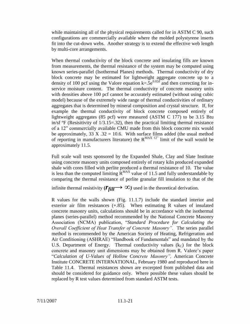
while maintaining all of the physical requirements called for in ASTM C 90, such
configurations are commercially available where the molded polystyrene inserts
fit into the cut-down webs. Another strategy is to extend the effective web length
by multi-core arrangements.
When thermal conductivity of the block concrete and insulating fills are known
from measurements, the thermal resistance of the system may be computed using
known series-parallel (Isothermal Planes) methods. Thermal conductivity of dry
block concrete may be estimated for lightweight aggregate concrete up to a
density of 100 pcf using the Valore equation k=.5e0.02d
and then correcting for in-
service moisture content. The thermal conductivity of concrete masonry units
with densities above 100 pcf cannot be accurately estimated (without using cubic
model) because of the extremely wide range of thermal conductivities of ordinary
aggregates that is determined by mineral composition and crystal structure. If, for
example the thermal conductivity of block concrete composed entirely of
lightweight aggregates (85 pcf) were measured (ASTM C 177) to be 3.15 Btu
in/sf ºF (Resisitivity of 1/3.15=.32), then the practical limiting thermal resistance
of a 12” commercially available CMU made from this block concrete mix would
be approximately, 33 X .32 = 10.6. With surface films added (the usual method
of reporting in manufacturers literature) the RMAX 12”
limit of the wall would be
approximately 11.5.
Full scale wall tests sponsored by the Expanded Shale, Clay and Slate Institute
using concrete masonry units composed entirely of rotary kiln produced expanded
shale with cores filled with perlite produced a thermal resistance of 10. The value
is less than the computed limiting RMAX
value of 11.5 and fully understandable by
comparing the thermal resistance of perlite granular fill insulation to that of the
infinite thermal resistivity (rfill→ ∞) used in the theoretical derivation.
R values for the walls shown (Fig. 11.1.7) include the standard interior and
exterior air film resistances (+.85). When estimating R values of insulated
concrete masonry units, calculations should be in accordance with the isothermal
planes (series-parallel) method recommended by the National Concrete Masonry
Association (NCMA) publication, “Standard Procedure for Calculating the
Overall Coefficient of Heat Transfer of Concrete Masonry”. The series parallel
method is recommended by the American Society of Heating, Refrigeration and
Air Conditioning (ASHRAE) “Handbook of Fundamentals” and mandated by the
U.S. Department of Energy. Thermal conductivity values (kC) for the block
concrete and masonry unit dimensions may be obtained from R. Valore’s paper
“Calculation of U-Values of Hollow Concrete Masonry”, American Concrete
Institute CONCRETE INTERNATIONAL, February 1980 and reproduced here in
Table 11.4. Thermal resistances shown are excerpted from published data and
should be considered for guidance only. Where possible these values should be
replaced by R test values determined from standard ASTM tests.

7/11/2007
11.1-22
F
i
g
u
r
e
X
.
T
h
e
r
Figure 11.1.7 Thermal Resistance of Masonry Walls Built
With Lightweight Aggregate Concrete Masonry Units and Integral Insulation
(Normalweight concretes in parenthesis)
The above schematic is based upon the following reports:
“Heat Transfer Observations of Lightweight Concrete Block Walls Before
and After Filling the Cores with Lightweight Aggregate”, Tests sponsored
by the Expanded Shale, Clay & Slate Institute, conducted at Institute for
Building Research at the Pennsylvania State University, June 15, 1967.
ESCSI Information Sheet #311. “Energy Efficient Buildings with
Lightweight Concrete Masonry”. Numbers in parentheses ( ) are R values
for HWCMU.
Grace Construction Products brochure, MI-277C 8/85, “Zonolite Masonry
Insulation”.
Tests conducted at the Institute for Building Research at Pennsylvania State
University, Sponsored by the Perlite Institute, September 28, 1964.
EnerBlock® brochure, “Insulated Concrete Masonry Wall”, West
Materials, Inc. 12/92.

7/11/2007
11.1-23
Thermal Resistance of Other Concrete Wall Systems
The series-parallel method can also be used to calculate the thermal resistance of
other concrete wall systems, such as tilt-up walls, precast walls, insulated
sandwich panels, and cast-in-place walls. Wall-shear connectors and solid-
concrete perimeters in sandwich panels can have relatively high thermal
conductivities and will act as thermal bridges in the same manner as webs do in
CMU’s. When these wall types do not contain thermal bridges, the series-parallel
equation can be simplified to a series equation that is, adding the resistances of
each layer because each layer has only one path.
Thermal Inertia – Thermal Mass
The terms thermal inertia or thermal mass describe the reluctance to change
temperature and the absorption and storage of significant amounts of heat in a
building or in walls of a building. Concrete and masonry change temperature
slower than many other building materials. This thermal inertia delays and
reduces heat transfer through a concrete or masonry wall, resulting in a reduction
in total heat loss or gain through the building envelope. With concrete or
masonry walls more heat is stored in the element and later released back into the
environment or room. Outdoor daily temperature cycles have a lesser effect on
the temperature inside a thermally massive building because massive materials
reduce heat transfer and moderate the indoor temperature.
Concrete and masonry walls often perform better than indicated by R-values
because R-values are determined under steady-state temperature conditions.
Thus, a thermally massive building will generally use less energy than a wood or
metal frame building insulated by materials of the same R-value. Laboratory tests
or computer simulations can be used to quantify the energy savings. These
methods have permitted building codes to allow lower R-values for mass walls
than for frame walls to achieve the same thermal performance.
Thermal diffusivity- Thermal diffusivity α indicates how quickly a material
changes temperature. It is calculated by
α = k/dcp = thermal diffusivity (in • ft³/h • ºF) [JW/m4] (12-6)
where
k = thermal conductivity (Btu • in./(h • ft² • ºF) [W/(m/m²K)];
d = density (lb/ft³) [kg/m³]; and
cp = specific heat (Btu/lb • ft²) [J/kg • K].

7/11/2007
11.1-24
A high thermal diffusivity indicates that heat transfer through a material will be
fast. Materials as for example metals, with a high thermal diffusivity respond
quickly to changes in temperature. Low thermal diffusivity means a slower rate
of heat transfer and a larger amount of heat storage. Materials with low thermal
diffusivity respond slowly to an imposed temperature difference. Materials with
low thermal diffusivities, such as concrete and masonry, are effective thermal
mass elements in a building.
Heat Capacity- Heat capacity is another indicator of thermal mass, one that is
often used in energy codes. Concrete and masonry, because they absorb heat
slowly, will generally have higher heat capacities than other materials. Heat
capacity is defined as the amount of heat necessary to raise the temperature of a
given mass one degree. More simply, it is the product of a mass and its specific
heat. In concrete or concrete masonry, the heat capacity of walls is determined by
multiplying the wall mass per area (lb/ft²) [kg/m²] by the specific heat (Btu/(lb •
ºF) [J/(kg • K] of the wall material. For example, a single-wythe masonry wall
weighing 34 lb/ft² (166 kg/m²) with a specific heat of 0.21 Btu(lb • ºF) [880 J/kg
•K] has a heat capacity of 7.14 Btu/(ft² • ºF) [46,080 J/(m²K)]. The total wall heat
capacity is simply the sum of the heat capacities of each wall component. Table
11.1.5 lists specific heat capacity values for concrete masonry materials.
Table 11.1.5 - Heat capacity of un-grouted hollow single wythe walls
(Btu/ft² • ºF)
Size of CMU and
% solid
Density of concrete in CMU, lb/ft³*
80 90 100 110 120 130 140
4 in.*
65 3.40 3.78 4.17 4.55 4.93 5.56 5.96
78 4.01 4.47 4.94 5.40 5.86 6.60 7.08
100 5.05 5.64 6.23 6.82 7.41 8.37 8.99
6 in. * 55 4.36 4.87 5.37 5.87 6.38 7.19 7.72
78 6.04 6.76 7.47 8.18 6.90 10.05 10.80
8 in.* 52 5.57 6.23 6.88 7.52 8.17 9.21 9.89
78 8.17 9.14 10.11 11.08 12.04 13.61 14.63
10 in.* 48 6.50 7.25 8.01 8.76 9.51 10.60 11.38
78 10.26 11.48 12.71 13.93 15.15 17.13 18.41
12 in.* 48 7.75 8.66 9.57 10.48 11.39 12.86 13.81
78 12.30 13.77 15.25 16.37 18.20 20.59 22.14 *Multiply Btu/h • ft² • ºF values by 5.68 to convert to W/m²K; multiply lb/ft³ values by 16 to
convert to kg/m³; multiply in. values by 25.4 to convert to mm.
Note: Face shell bedding (density of mortar = 120 lb/ft³; specific heat of mortar = 0.20 [Btu/lb •
ºF]
From NCMA TEK 6-16, National Concrete Masonry Association, 1989.
Insulation – The physical location of wall insulation relative to wall mass also
significantly affects thermal performance. In concrete masonry walls, insulation
can be placed on the interior of the wall, integral with the masonry, or on the

7/11/2007
11.1-25
exterior. For maximum benefit the exterior wall thermal mass should be in direct
contact with the conditioned air. Because insulation on the interior of the mass
thermally isolates the mass from the conditioned space, exterior insulation
strategies are usually recommended. For example, rigid board insulation applied
on the wall exterior, with a finish applied over the insulation, is more energy
efficient than furring out the interior of a mass wall and installing batt insulation.
Integral insulation strategies include insulating the cores of a masonry unit, using
an insulated concrete sandwich panel, or insulating the cavity of a double-wythe
masonry wall. In these cases, mass is on both sides of the insulation. Integral
insulation allows greater thermal mass benefits than interior insulation but not as
much as exterior insulation.
Daily temperature changes – A structure can be designed for energy savings by
using the thermal mass effect to introduce thermal lag, which delays and reduces
peak temperatures. Figure 9a illustrates the thermal lag for an 8 in. (20mm)
concrete wall. When outdoor temperatures are at their peak, the indoor air
remains relatively unaffected because the outdoor heat has not had time to
penetrate the mass. By nightfall, when outside temperatures are falling, the
exterior wall mass begins to release the heat stored during the day, moderating its
effect on the interior conditioned space. Temperature amplitudes are reduced and
never reach the extremes of the outdoor temperatures. Figure 9b represents an
ideal climate condition for thermal mass in which large outdoor daily temperature
swings do not create uncomfortable indoor temperatures due to the mass wall’s
ability to moderate heat flow into the building. Thermal mass benefits are greater
in seasons having large daily temperature swings, as can occur during the spring
and fall. In cold climates, the thermal mass effect can be used to collect and store
solar energy and internal heat gains generated by office and mechanical
equipment. These thermal gains are later reradiated into the conditioned space,
thus reducing the heating load. During the cooling season, these same solar and
internal gains can be dissipated using night-ventilation strategies (circulating
cooler outdoor air over the thermal mass materials or walls). The night venting
cools the thermal mass, allowing the interior of the building to remain cool well
into the day, reducing the cooling loads and to shifting peak loads.
Building design – Building design and use can impact thermal mass because
different buildings use energy in different ways. In low-rise residential
construction, heating and cooling are influenced by the thermal performance of
the building envelope. These buildings are said to have skin-dominated thermal
loads, and the effects of exterior thermal mass for low-rise residential buildings
are influenced primarily by climate and wall construction.
On the other hand, the thermal mass of commercial and high-rise residential
buildings is significantly affected by internal heat gains in addition to the climate
and wall construction. Large internal heat gains from lighting, equipment,
occupants, and solar transmission through windows create a greater need for
interior thermal mass to absorb heat and delay heat flow. Also, commercial

7/11/2007
11.1-26
buildings generally have peak cooling loads in the afternoon and have low or no
occupancy in the evening. Therefore, delaying the peak load from the afternoon
to the evening saves substantial energy because the peak then occurs when the
building is unoccupied and sensors can be shifted to a nighttime setting. The
benefits of thermal mass in commercial buildings are generally greater than for
low-rise residential buildings.
Physical testing and computer simulations may be used to estimate the dynamic
thermal performance of concrete and masonry walls and buildings. The calibrated
hot box (ASTM C 976) can be used to determine the dynamic thermal
performance of concrete and masonry wall sections. These tests are usually
limited to 8 ft² (0.74 m²) sections of the opaque wall. A computer is needed to
simulate the complex interactions of all building envelope components under
constantly varying climatic conditions.
Calibrated hot-box facilities – Calibrated hot-box test facilities are used to
determine the static and dynamic response of wall specimens to indoor and
outdoor temperatures. The hot box consists of two highly insulated chambers
clamped tightly together to surround the test wall. Air in each chamber is
conditioned by heating and cooling equipment to obtain desired temperatures on
each side of the test wall.
The outdoor (climatic) chamber is cycled between various temperatures. These
temperature cycles can be programmed to simulate outdoor daily temperature
swings. The indoor (metering) chamber is typically maintained at a constant
temperature between 65 and 80 ºF (18 and 27 ºC) to simulate indoor room
conditions.
The chambers and test specimens are instrumented to monitor air and surface
temperatures on both sides of the test wall and heating energy input to the indoor
chamber. Instruments monitor the energy required to maintain a constant indoor
temperature while the outdoor temperature is varied. This energy, when corrected
for small thermal losses through the frame, provides a measure of transient heat
flow through the test wall.
The calibrated hot box is used to quantify the time lag between outdoor and
indoor peak temperatures and the reduction in peak temperatures from outside to
inside. The time lag shows the response time of a mass wall to outdoor
temperature fluctuations. A long time lag and amplitude reduction relieve
excessive cycling of the heating, ventilating, and air conditioning (HVAC)
equipment and increase system efficiency. Additional cost savings can result
where utility companies offer reduced off-peak energy rates. With a reduction in
peak temperatures, less cooling capacity is needed, and the cooling capacity of the
HVAC system can frequently be reduced. Similar savings occur for heating.
Thermal lag depends on the R-value as well as the heat capacity because both of
these factors influence the rate of heat flow through a wall.
7/11/2007
11.1-27
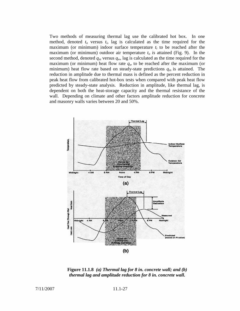
Two methods of measuring thermal lag use the calibrated hot box. In one
method, denoted to versus ti, lag is calculated as the time required for the
maximum (or minimum) indoor surface temperature ti to be reached after the
maximum (or minimum) outdoor air temperature to is attained (Fig. 9). In the
second method, denoted qss versus qw, lag is calculated as the time required for the
maximum (or minimum) heat flow rate qw to be reached after the maximum (or
minimum) heat flow rate based on steady-state predictions qss is attained. The
reduction in amplitude due to thermal mass is defined as the percent reduction in
peak heat flow from calibrated hot-box tests when compared with peak heat flow
predicted by steady-state analysis. Reduction in amplitude, like thermal lag, is
dependent on both the heat-storage capacity and the thermal resistance of the
wall. Depending on climate and other factors amplitude reduction for concrete
and masonry walls varies between 20 and 50%.
Figure 11.1.8 (a) Thermal lag for 8 in. concrete wall; and (b)
thermal lag and amplitude reduction for 8 in. concrete wall.
7/11/2007
11.1-28
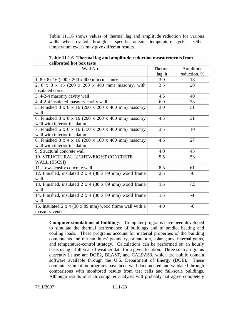
Table 11.1.6 shows values of thermal lag and amplitude reduction for various
walls when cycled through a specific outside temperature cycle. Other
temperature cycles may give different results.
Table 11.1.6- Thermal lag and amplitude reduction measurements from
calibrated hot box tests
Wall No. Thermal
lag, h
Amplitude
reduction, %
1. 8 x 8x 16 (200 x 200 x 400 mm) masonry 3.0 18
2. 8 x 8 x 16 (200 x 200 x 400 mm) masonry, with
insulated cores.
3.5 28
3. 4-2-4 masonry cavity wall 4.5 40
4. 4-2-4 insulated masonry cavity wall 6.0 38
5. Finished 8 x 8 x 16 (200 x 200 x 400 mm) masonry
wall
3.0 51
6. Finished 8 x 8 x 16 (200 x 200 x 400 mm) masonry
wall with interior insulation
4.5 31
7. Finished 6 x 8 x 16 (150 x 200 x 400 mm) masonry
wall with interior insulation
3.5 10
8. Finished 8 x 4 x 16 (200 x 100 x 400 mm) masonry
wall with interior insulation
4.5 27
9. Structural concrete wall 4.0 45
10. STRUCTURAL LIGHTWEIGHT CONCRETE
WALL (ESCSI)
5.5 53
11. Low-density concrete wall 8.5 61
12. Finished, insulated 2 x 4 (38 x 89 mm) wood frame
wall
2.5 -6
13. Finished, insulated 2 x 4 (38 x 89 mm) wood frame
wall
1.5 7.5
14. Finished, insulated 2 x 4 (38 x 89 mm) wood frame
wall
1.5 -4
15. Insulated 2 x 4 (38 x 89 mm) wood frame wall with a
masonry veneer
4.0 -6
Computer simulations of buildings – Computer programs have been developed
to simulate the thermal performance of buildings and to predict heating and
cooling loads. These programs account for material properties of the building
components and the buildings’ geometry, orientation, solar gains, internal gains,
and temperature-control strategy. Calculations can be performed on an hourly
basis using a full year of weather data for a given location. Three such programs
currently in use are DOE2, BLAST, and CALPAS3, which are public domain
software available through the U.S. Department of Energy (DOE). These
computer simulation programs have been well documented and validated through
comparisons with monitored results from test cells and full-scale buildings.
Although results of such computer analyses will probably not agree completely

7/11/2007
11.1-29
with actual building performance, relative values between computer-modeled
buildings and the corresponding actual buildings are in good agreement.
Interior Thermal Mass - Up to this point, most of the information presented in
this chapter has focused on the effects of thermal mass in the exterior envelopes
of buildings. Concrete and masonry can also help improve building occupant
comfort and save additional energy when used in building interiors. When
designing interior mass components, R-values are not important because there is
no significant heat transfer through an interior wall or floor. Instead, heat is
absorbed from the room into the mass then re-released back into the room. In
other words, the interior mass acts as a storage facility for energy. A concrete
floor in a sunroom absorbs solar energy during the day, then releases the stored
warmth during the cooler nighttime hours.
Interior thermal mass acts to balance temperature fluctuations within a building
that occur from day to night or from clouds intermittently blocking sunlight.
Because of this flywheel effect, the temperature inside a building changes slowly.
This keeps the building from cooling to fast at night during the heating season or
heating to quickly during the day in the cooling season.
To use interior thermal mass effectively, carefully choose the heat capacity and
properly locate the concrete and masonry components. Concrete or masonry as
thin as 3 in. (75 mm) is sufficient to moderate the interior temperature because
surface area is more important than thickness for interior thermal mass. A large
surface area in contact with conditioned air tends to stabilize interior
temperatures. Concrete or masonry distributed in a thin layer over the walls and
floors of interior rooms is more effective than the same amount of mass placed in
one thick, solid thermal mass wall. Other designs may require different
placements of thermal mass. For passive solar applications, the mass should be in
direct contact with the sunlight for maximum effectiveness.
Thermal Properties for Passive Solar Design
Passive solar buildings use three basic components: glazing, thermal mass, and
ventilation. South-facing glass is used as the heat collector. Glass in other parts
of the building is minimized to reduce heat loss or unwanted heat gain. Thermal
mass is used to store heat gained through the glass and to maintain interior
comfort. The building ventilation system distributes air warmed by solar gains
throughout the building.
Passive solar buildings require a thermal mass to adequately store solar gains and
maintain comfort in both heating and cooling seasons. The heat-storage capacity
of concrete and masonry materials is determined by a variety of thermal
properties, such as absorbtivity, conductivity, specific heat, diffusivity and
emissivity. This section describes these properties, discusses their impact on
passive solar buildings, and provides design values. These data allow designers to

7/11/2007
11.1-30
more accurately predict the performance of thermal storage mass and to choose
appropriate materials for a particular design.
Thermal properties of the storage mass must be known to size HVAC equipment,
maintain comfort in the building, and determine the optimal amount and
arrangement of the thermal mass. For most passive solar applications, heat
energy absorbed during the day is preferably released at night, as opposed to the
next day. Therefore, the thermal mass storage effectiveness depends on the heat-
storage capacity of the mass and rate of heat flow through the mass.
Conductivity, defined earlier, indicates how quickly or easily heat flows through a
material. In passive solar applications, conductivity allows the solar heat to be
transferred beyond the surface of the mass for more effective storage. Materials
with very high conductivity values, however, should be avoided because high
conductivity can shorten the time lag for heat delivery.
The amount of heat absorbed by a wall depends on its absorbtivity and the solar
radiation incident on the wall. Absorbtivity is a measure of the efficiency of
receiving radiated heat and is the fraction of incident solar radiation that is
absorbed by a given material, as opposed to being reflected or transmitted. For
opaque materials, such as concrete and masonry, solar radiation not absorbed by
the wall is reflected away from it. Absorbtivity is a relative value; and
absorbtivity of 1.0 indicates that a material absorbs all incident radiated heat and
reflects none.
The absorbtivity of nonmetallic materials is a surface effect largely dependent on
surface color. Dark surfaces have higher absorbtivities than light surfaces
because they absorb more heat, while light surfaces reflect more heat than they
absorb.
Sunlit thermal-mass floors should be relatively dark in color to absorb and store
heat more efficiently. Robinson (1980) concludes that reds, browns, blues, and
blacks will perform adequately for passive solar storage. Nonmass walls and
ceilings should be light in color to reflect solar radiation to the thermal storage
mass and to help distribute light more evenly.
Rough-textured surfaces, such as split-faced block or stucco, provide more
surface area for collection of solar energy than smooth surfaces, but this
advantage in solar energy collection has not been thoroughly investigated. Solar
absorbtivity is usually determined using ASTM E 434. This test subjects a
specimen to simulated solar radiation. Radiant energy absorbed by a specimen
and emitted to the surroundings causes the specimen to reach an equilibrium
temperature that is dependent on the ratio of absorbtivity to emissivity. Solar
absorbtivity is then determined from the known emissivity.
Emissivity, sometimes called emittance, describes how efficiently a material
transfers energy by radiation heat transfer or how efficiently a material emits

7/11/2007
11.1-31
energy. Like absorbtivity, emissivity is a unitless value defined as the fraction of
energy emitted or released from a material, relative to the radiation of a perfect
emitter or blackbody. For thermal storage, high-emissivity materials are used to
effectively release stored solar heat into the living areas.
The ability of a material to emit energy increases as the temperature of the
material increases. Therefore, emissivity is a function of temperature and
increases with increasing temperature. For the purposes of passive solar building
design, emissivity values at room temperature are used. Mazria (1979) and other
researchers frequently assume an emissivity value of 0.90 for all nonmetallic
building materials.
Emissivity is determined using either emitter or receiver methods. An emitter
method involves measuring the amount of energy required to heat a specimen and
the temperature of the specimen. A receiver method such as ASTM E 408
measures emitted radiation directed into a sensor.
Specific heat defined earlier, is a material property that describes the ability of a
material to store heat. Specific heat is the ratio of the amount of heat required to
raise the temperature of a given mass of material by one degree to the amount of
heat required to raise the temperature of an equal mass of water by one degree.
Materials with high specific heat values are effectively used for thermal storage in
passive solar designs. Values of specific heat for concrete and masonry materials
vary between 0.19 and 0.22 Btu/lb ● ºF (0.79 and 0.92 kl/kg ● K) (ACI 122)
(Table 11..1.7).
Some heat-capacity defined earlier, storage is present in all buildings in the
framing, gypsum board, furnishings, and floors. Home furnishings typically have
a heat capacity of approximately 0.18 Btu/(h ● ºF). A larger amount of thermal
mass, however, is required in passive solar buildings. Walls and floors with high
heat capacities are desirable for passive solar storage applications.
In addition to heat capacity, another property that is often used in passive solar
design references is thermal diffusivity. Thermal diffusivity is a measure of heat
transport relative to energy storage and is defined earlier. Materials with high
thermal diffusivities are more effective at heat transfer than heat storage.
Therefore, materials with low thermal diffusivities are desirable for storing solar
energy.

7/11/2007
11.1-32
Table 11.1.7 Thermal Properties of Various Building Materials Thermal Resistance (R),
and Heat Capacity (HC)
Building material R-values are from 1989 ASHRAE Handbook of Fundamentals, chapter 22. HC-values are
calculated from Density and Specific Heat from the same source, except as noted other wise.
MATERIAL DESCRIPTION
PER THICKNESS LISTED
THICKNESS
(in.)
R VALUE
(h•ft²•ºF / Btu)
HC VALUE
(Btu / ft² • ºF)
WEIGHT
(pounds / ft²)
BUILDING BOARD
Gypsum Wallboard 0.5 0.45 0.54 2.1
Plywood (Douglas Fir) 0.5 0.62 0.41 1.4
Fiber board sheathing, regular density 0.5 1.32 0.23 0.8
Hardboard, medium density 0.5 0.69 0.65 2.1
Particleboard, medium density 0.5 0.53 0.65 2.1
INSULATING MATERIALS
Mineral Fiber With Metal Stud Framing1
R-11, 2x4 @ 16” (R-11 x .50 correction factor) 5.50 0.30 1.7
R-11, 2x4 @ 24” (R-11 x .60 correction factor) 6.60 0.27 1.4
R-19, 2x6 @ 16” (R-19 x .40 correction factor) 7.60 0.44 2.4
R-19, 2x6 @ 24” (R-19 x .45 correction factor) 8.55 0.39 1.9
Mineral Fiber With Wood Framing2 (with
lapped
siding, 1/2” sheathing, and 1/2” gypsum board)
R-11, 2x4 @ 16” on center 12.44 2.01 6.1
R-19, 2x6 @ 24” on center 19.11 2.13 6.5
Board, Slabs, and Loose Fill
Cellular glass 1 2.86 0.13 0.7
Expanded polystyrene, extruded 1 5.00 0.08 0.3
Expanded polystyrene, molded beads3
1 4.00 0.03 0.1
Perlite3
1 3.13 0.11 0.4
Polyurethane 1 6.25 0.05 0.5
UF Foam4
1 4.35 0.02 0.1
Vermiculite3
1 2.44 0.13 0.4
Expanded Shale, Clay & Slate LWA5
30# / CF Dry loose weight 1 1.21 0.53 2.5
40# / CF Dry loose weight 1 1.02 0.70 3.3
50# / CF Dry loose weight 1 0.88 0.88 4.2
Mortar3, Plaster & Misc. Masonry
Clay brick masonry 3.63 0.40 8.16 40.8
Stucco and cement plaster, sand aggregate 1 0.20 1.93 9.7
Gypsum plaster, perlite aggregate 1 0.67 1.20 3.8
Mortar 1 0.20 2.00 10.0
CONCRETE3 (cast in place, precast)
60 pcf 1 0.60 1.05 5.0
70 pcf 1 0.49 1.23 5.8
80 pcf 1 0.40 1.40 6.7
90 pcf 1 0.33 1.58 7.5
100 pcf 1 0.27 1.75 8.3
110 pcf 1 0.22 1.93 9.2
120 pcf 1 0.18 2.10 10.0
135 pcf 1 0.13 2.48 11.3
150 pcf 1 0.10 2.75 12.5
WOODS
Southern Pine 1 1.00-0.89 1.16-1.34 3.0-3.4
California Redwood 1 1.35-1.22 0.80-0.91 2.0-2.3
1. R-Value corrected per ASHRAE / IES 90.1-1989 8C2; HC from vendors’ data
2. Calculated per ASHRAE 1989 FUNDAMENTALS, Chapter 22
3. NCMA TEK 164 and NCMA “Concrete Masonry R-Value Program”
4. NBS Tech Note 946
5. R-Values from Thermophysical Properties of Masonry and its Constituents”, Part I, by Rudolph Valore, Jr.
11.1-33
Incorporating Mass into Passive Solar Designs - In addition to the material
properties discussed here, location of thermal mass materials is also important in
passive solar applications. For most materials, the effectiveness of thermal mass
in the floor or interior wall increases proportionally with a thickness up to
approximately 3 to 4 inch (75 to 100 mm). Beyond that, the effectiveness does
not increase as significantly. A 4 in. (100 mm) thick mass floor is about 30%
more effective at storing direct sunlight than a 2 in. (50 mm) thick mass floor. A
6 in. (150 mm) thick mass floor, however, will only perform about 8% better than
the 4 in. (100 mm) floor. For most applications, 3 to 4 inc. (75 to 100 mm) thick
mass walls and floors maximize the amount of storage per unit of wall or floor
material, unless thicker elements are required for structural or other
considerations. Distributing thermal mass evenly around a room stores heat more
efficiently and improves comfort by reducing localized hot or cold spots.
Location of thermal mass within a passive solar building is also important in
determining a building’s efficiency and comfort. Mass located in the space where
solar energy is collected is about four times more effective than mass located
outside the collection area. If the mass is located away from the sunlit area, it is
considered to be convectively coupled. Convectively coupled mass provides a
mechanism for storing heat away from the collection area through natural
convection and improves comfort by damping indoor temperature swings.
Covering mass walls and floors with materials having R-values larger than
approximately 0.5 h • ft² • ºF/Btu (0.09 m²K/W) and low thermal diffusivities will
reduce the daily heat-storage capacity. Coverings such as surface bonding, thin
plaster coats, stuccos, and wallpapers do not significantly reduce the storage
capacity. Materials such as cork, paneling with furring and sound boards are best
avoided. Direct attachment of gypsum board is acceptable if it is firmly adhered
to the block or brick wall surface (no air space between gypsum board and
masonry). Exterior mass walls should be insulated on the exterior or witin the
cores of concrete block to maximize the effectiveness of the thermal mass.
Thermal mass can easily be incorporated into the floors. If mass is used in floors,
it will be much more effective if sunlight falls directly on it. Effective materials
for floors include painted, colored, or vinyl-covered concrete; brick or concrete
pavers; quarry tile; and dark-colored ceramic tile.
As more south-facing glass is used, more thermal mass should be provided to
store heat gains and prevent the building from overheating. Although the concept
is simple, in practice the relationship between the amount of glazing and the
amount of mass is complicated by many factors. From a comfort standpoint, it
would be difficult to add too much mass. Thermal mass will hold solar gains
longer in winter and keep buildings cooler in summer. Thermal mass has a cost,
however, so adding too much can be uneconomical. Design guidance on passive
solar buildings is beyond the scope of this reference manual.
Summary- -Passive solar buildings represent a specialized application of thermal
mass for solar heat storage, retention and re-radiation. To accomplish these tasks,

7/11/2007
11.1-34
the storage medium should have certain thermal characteristics. Thermal
conductivity should be high enough to allow the heat to penetrate into the storage
material but not so high that the storage time or thermal lag is shortened. Solar
absorbtivity should be high, especially for mass floors, to maximize the amount of
solar energy that can be stored.
Thermal storage materials should have high-emissivity characteristics to
efficiently reradiate the stored energy back into the occupied space. Specific heat
and heat capacity should be high to maximize the amount of energy that can be
stored in a given amount of material.
Concrete and masonry materials fulfill all of these requirements for effective
thermal storage. These materials have been used with great success in passive
solar buildings to store the collected solar energy, prevent overheating, and
reradiate energy to the interior space when needed.
Condensation Control
Moisture condensation on the interior surfaces of a building envelope is unsightly
and can cause damage to the building or its contents. Moisture condensation
within a building wall or ceiling assembly can be even more undesirable because
it may not be noticed until damage has occurred. In addition increased moisture
trapped in the wall lowers the thermal resistance considerably.
Air contains water vapor, and warm air carries more water vapor than cold air.
Moisture, in the form of water vapor, is added to the air by respiration,
perspiration, bathing, cooking, laundering, humidifiers, and industrial processes.
When the air contacts cold surfaces, the air may be cooled below its dew point,
permitting condensation to occur. Dew point is the temperature at which water
vapor condenses.
Once condensation occurs, the relative humidity of the interior space of a building
cannot be increased because any additional water vapor will simply condense on
the cold surface. The inside wall surface temperature of a building assembly
effectively limits the relative humidity of air contained in an interior space.
Prevention of Condensation on Wall Surfaces Under Steady-State Analysis -
Condensation on interior surfaces can be prevented by using materials with high
thermal resistance such that the surface temperature will not fall below the dew
point temperature of the air in the room. The amount of thermal resistance that
should be provided to avoid condensation can be determined from the following
relationship.
)(
)(1
si
otft
tt
ttRR

7/11/2007
11.1-35
C).(º Fº re temperatupoing dewor ,saturation
and C);(º Fº atureair temperoutdoor t
C);(º Fº atureair temperindoor
);/(/ºfth filmair surfaceinterior of resistance thermal
);/(/ºft hassembly wallof resistance thermalR
o
22
22t
s
i
ft
t
t
WKmBtuFR
WKmBtuF
Due to lag time associated with the thermal mass effect, the steady-state analysis
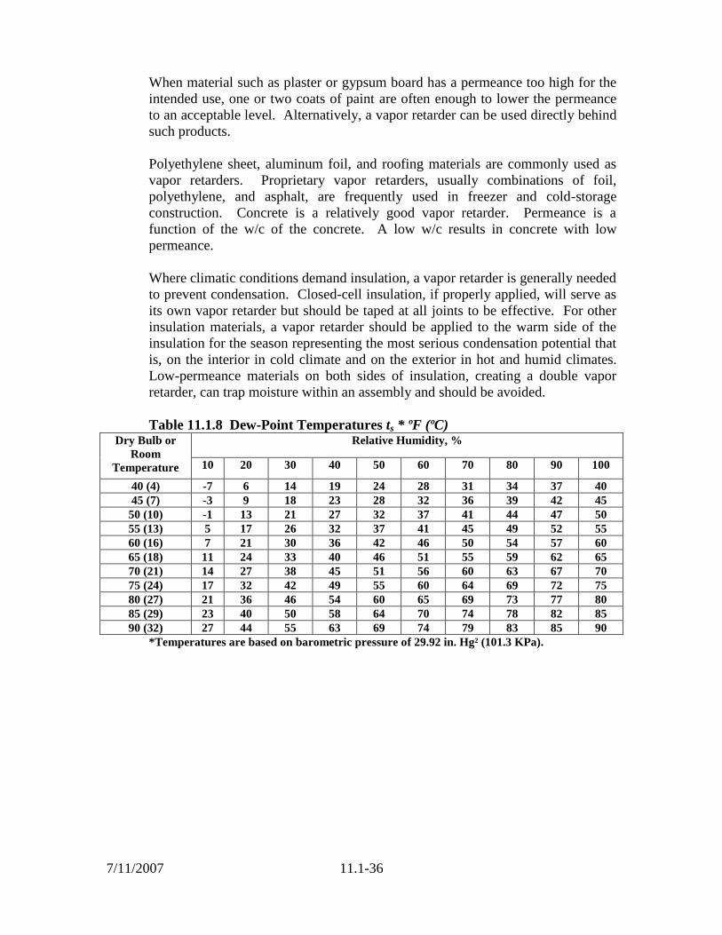
of condensation is conservative for masonry walls. Dew point temperatures to the
nearest degree Fahrenheit for various values of ti and relative humidity are shown
in Table 11.1.8.
For example, Rt is to be determined when the room temperature and relative
humidity are 70 ºF (21 ºC) and 40% respectively, and to during the heating season
is -10 ºF (-24 ºC). From Table 11.6, the dew point temperature ts is 45 ºF (7 ºC)
and because the resistance of the interior air film fi is 0.68 h • ft² • ºF/Btu (0.12
m²K/W)
]/38.0[/º18.24570
)10(7068.0
/12.0/º68.0
22
22
WKmBtuFfthR
WKmBtuFfthR
t
ft
Prevention of Condensation within Wall Constructions - Water vapor in air is
a gas and it diffuses through building materials at rates that depend on vapor
permeabilities of materials and vapor-pressure differentials. Colder outside air
temperatures increase the water-vapor-pressure differential with the warm inside
air; this increases the driving force moving the inside air to the outside.
Leakage of moisture-laden air into an assembly through small cracks can be a
greater problem than vapor diffusion. The passage of water vapor through a
material is, in itself, generally not harmful. It becomes of consequence when, at
some point along the vapor flow path, vapors fall below the dew point
temperature and condense.
Water-vapor permeability and permeances of some building materials are shown
in Table 11.1.9. Water-vapor permeability μ (gr/h•ft² •(in.Hg)/in.)(ng/s•m•Pa) is
defined as the rate of water-vapor transmission per unit area of a body between
two specified parallel surfaces induced by a unit vapor-pressure difference
between the two surfaces. When properly used, low-permeability materials keep
moisture from entering a wall or roof assembly, whereas high permeability
materials allow moisture to escape. Water-vapor permeance M is defined as the
water-vapor permeability for a thickness other than the unit thickness to which μ
refers. Hence, M = μ/l where l is the flow path, or material, thickness (gr/(h • ft² -
[in.Hg])(ng/s •m²•Pa).
7/11/2007
11.1-36
When material such as plaster or gypsum board has a permeance too high for the
intended use, one or two coats of paint are often enough to lower the permeance
to an acceptable level. Alternatively, a vapor retarder can be used directly behind
such products.
Polyethylene sheet, aluminum foil, and roofing materials are commonly used as
vapor retarders. Proprietary vapor retarders, usually combinations of foil,
polyethylene, and asphalt, are frequently used in freezer and cold-storage
construction. Concrete is a relatively good vapor retarder. Permeance is a
function of the w/c of the concrete. A low w/c results in concrete with low
permeance.
Where climatic conditions demand insulation, a vapor retarder is generally needed
to prevent condensation. Closed-cell insulation, if properly applied, will serve as
its own vapor retarder but should be taped at all joints to be effective. For other
insulation materials, a vapor retarder should be applied to the warm side of the
insulation for the season representing the most serious condensation potential that
is, on the interior in cold climate and on the exterior in hot and humid climates.
Low-permeance materials on both sides of insulation, creating a double vapor
retarder, can trap moisture within an assembly and should be avoided.
Table 11.1.8 Dew-Point Temperatures ts * ºF (ºC) Dry Bulb or
Room
Temperature
Relative Humidity, %
10 20 30 40 50 60 70 80 90 100
40 (4) -7 6 14 19 24 28 31 34 37 40
45 (7) -3 9 18 23 28 32 36 39 42 45
50 (10) -1 13 21 27 32 37 41 44 47 50
55 (13) 5 17 26 32 37 41 45 49 52 55
60 (16) 7 21 30 36 42 46 50 54 57 60
65 (18) 11 24 33 40 46 51 55 59 62 65
70 (21) 14 27 38 45 51 56 60 63 67 70
75 (24) 17 32 42 49 55 60 64 69 72 75
80 (27) 21 36 46 54 60 65 69 73 77 80
85 (29) 23 40 50 58 64 70 74 78 82 85
90 (32) 27 44 55 63 69 74 79 83 85 90
*Temperatures are based on barometric pressure of 29.92 in. Hg² (101.3 KPa).

7/11/2007
11.1-37
Table 11.1.9 Typical Permeance (M) and Permeability (μ) Values. Material M** perm Μ**perm-in.
Concrete (1:2:4 mixture)** 3.2
Wood (sugar pine) --- 0.4 to 5.4
Expanded polystyrene (extruded) --- 1.2
Paint-two coats
Asphalt paint on plywood 0.4 ---
Enamels on smooth plaster 0.5 to 1.5 ---
Various primers plus one coat flat oil paint on plaster 1.6 to 3.0 ---
Expanded polystyrene (bead) --- 2.0 to 5.8
Plaster on gypsum lath (with studs) 20.00 ---
Gypsum wallboard, 0.375 in. (9.5 mm) 50.00 ---
Polyethylene, 2 mil (0.05 mm) 0.16 ---
Aluminum foil, 0.35 mil (0.009 mm) 0.05 ---
Aluminum foil, 1 mil (0.03 mm) 0.00 ---
Built-up roofing (hot mopped) 0.00 ---
Duplex sheet, asphalt laminated aluminum foil one side 0.002 ---

11.2-1
11.2 Fire Resistance of Lightweight Concrete and Masonry
Definition of Terms
Fire Endurance - A measure of the elapsed time during which a material or
assembly continues to exhibit fire resistance under specified conditions of test and
performance. As applied to elements of buildings, fire endurance shall be
measured by the methods and to the criteria defined by ASTM Methods E 119,
“Standard Methods of Fire Tests of Building Construction and Materials.” (Fire
endurance is a technical term).
Fire Resistance - The property of a material or assembly to withstand fire or give
protection from it. As applied to elements of buildings, fire resistance is
characterized by the ability to confine a fire or to continue to perform a given
structural function, or both. (Fire resistance is a descriptive term.)
Fire Rating - A time required, usually expressed in hours, for an element in a
building to maintain its particular fire-resistant properties. Model codes establish
the required fire ratings for various building elements. (Fire rating or fire-
resistance rating is a legal term.)
Standard Fire Tests
Fire-endurance periods for building components are normally determined by
physical tests conducted according to ASTM E 119, “Standard Methods of Fire
Tests of Building Construction and Materials.” Provisions of the ASTM E 119
test require that specimens be subjected to a fire which follows the standard time-
temperature curve shown in Fig. 11.2.1.
Figure 11.2.1 ASTM Standard E 119 Time-Temperature Curve.

11.2-2
Under the E 119 standard, the fire endurance of a member or assembly is
determined by the time required to reach the first of any of the following three
end points:
1. Ignition of cotton waste due to passage of flame through cracks or
fissures.
2. A temperature rise of 325ºF (single point) or 250ºF (average) on the
unexposed surface of the member or assembly. This is known as the
heat transmission end point.
3. Inability to carry the applied design load, that is, structural collapse.
Additional rating criteria for the fire endurance of a member or assembly include:
1. Concrete structural members: in some cases the average temperature of
the tension steel at any section must not exceed 800ºF for cold-drawn
prestressing steel or 1100ºF for reinforcing bars. Tests show that the
respective steels retain approximately 50% of their original yield
strength at these temperatures.
2. For wall sections: the ability to resist the impact, erosion, and cooling
effects of a specific size hose stream.
Table 11.2.1 presents a listing of ASTM E 119 end-point criteria and test
conditions and outlines applicable end points of various concrete and masonry
members and assemblies.
ASTM E 119 classifies beams, floors, and roofs as either restrained or
unrestrained. A restrained member is one in which the thermal expansion is
restricted. Reinforced concrete assemblies are generally classified as restrained if
they have continuity at interior supports or are restricted from lateral movement as
exterior supports. Table 11.2.2 should be referenced when determining the
presence of thermal restraint.
The model code requires fire testing in accordance with ASTM E 119 or
analytical calculation based on ASTM E 119 test data to satisfy all fire-resistance
ratings required by the codes. These recently approved analytical methods
present significant cost savings when compared to actual ASTM E 119 fire
testing.
End-Point Criteria and Analytical Methods - To analytically calculate the fire
endurance of a given member it is useful to understand which end-point criteria
will govern design of that member. As previously discussed, the first end point
reached during the E 119 fire tests establishes the fire endurance period of the
member. To further aid in understanding applicability of various end-point
criteria see Table 11.2.1.

11.2-3
Walls - Concrete and masonry walls nearly always fail the heat transmission end
point before allowing passage of flame or failing structurally. By examining heat
transmission through various thicknesses of concrete, made with various types of
aggregates, from E 119 fire tests it is possible to determine a given thickness or
equivalent thickness of concrete, masonry, or brick to limit the temperature rise to
below 250ºF (average) or to 325ºF (single point) as specified in ASTM E 119.
Beams - Prestressed and normally reinforced concrete beams cannot be so easily
categorized. The ability of a beam to carry a design load is the primary end point
and is dependent on several factors which are accounted for in rational design
methods.
Floors and Roofs - Calculation of fire endurance of reinforced and prestressed
concrete roof and floor slabs is based on both analyses of heat transmission and of
load-carrying capacity at elevated temperatures. The heat transmission end point
can be analyzed similarly to walls. As with beams, the ability of roofs and floors
to carry load is influenced by several factors in design. Tabulated values for
concrete cover, similar to those for beams, exist for roof and floor slabs and are
shown in Table 11.2.1.

11.2-4
Table 11.2.1-Applicable End-Point Criteria and Test Conditions for Concrete and
Masonry Members and Assemblies (Based on ASTM E 119 Standard Fire Tests) End
point
Member
250 F
average
temperature
rise or 325
F point
temp. rise
on
unexposed
surface
Flame
impingement
through
cracks or
fissures
sufficient to
ignite cotton
waste
Carry
applied
load
Steel
temperature
end point
Restrained
during
testing
Hose
stream test
Walls
Bearing
Nonbearing
Yes
Yes
Yes
Yes
Yes
No load
applied
Not considered
Not considered
No1
Yes1
Yes2
Yes2
Floors
and
roofs
Restrained
Unrestrained
Yes
Yes
Yes
Yes
Yes
Yes
No3
No
Yes
No
No
No
Columns
No
No
Yes
No
Restraint
not
imposed:
test specifies
simulation
of end
connection
No
Individual beams-
restrained:
prestressed or
reinforced
No
No
Yes
Yes4
Yes
No
Individual beams-
unrestrained:
prestressed or
reinforced
No
No
Yes
No
No
No
1Non-load-bearing walls are restrained but not loaded during tests. Bearing walls are loaded but not
restrained. 2Hose stream tests apply only to those walls required to have a one-hour rating or greater.
3Restrained floor and roof slabs utilizing concrete beams spaced greater than 4′ center-to-center must not
exceed steel temperature limits of 1100ºF (reinforcing steel) and 800ºF (prestressed steel) for one-half the
rating period or 1 hour, whichever is greater.* 4Reinforcing steel I concrete beams or joists spaced greater than 4′ center-to-center and cast monolithically
with floors and columns must be maintained below 800ºF (prestressing) and 1100ºF (reinforcing) for 1
hours or one-half the desired rating period, whichever is greater.
*ESCSI Note: The fact that ASTM E 119 permits the acceptance of fire resisting walls for
ratings greater than one hour without exposing the same wall to a hose stream test should be
pointed out to design professionals. The following addition to usual masonry specifications
should be suggested “Hose steam testing shall be conducted at, or in excess of, the fire
endurance rating time specified”.
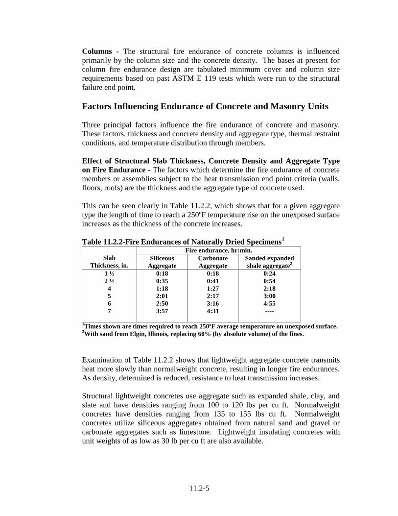
11.2-5
Columns - The structural fire endurance of concrete columns is influenced
primarily by the column size and the concrete density. The bases at present for
column fire endurance design are tabulated minimum cover and column size
requirements based on past ASTM E 119 tests which were run to the structural
failure end point.
Factors Influencing Endurance of Concrete and Masonry Units
Three principal factors influence the fire endurance of concrete and masonry.
These factors, thickness and concrete density and aggregate type, thermal restraint
conditions, and temperature distribution through members.
Effect of Structural Slab Thickness, Concrete Density and Aggregate Type
on Fire Endurance - The factors which determine the fire endurance of concrete
members or assemblies subject to the heat transmission end point criteria (walls,
floors, roofs) are the thickness and the aggregate type of concrete used.
This can be seen clearly in Table 11.2.2, which shows that for a given aggregate
type the length of time to reach a 250ºF temperature rise on the unexposed surface
increases as the thickness of the concrete increases.
Table 11.2.2-Fire Endurances of Naturally Dried Specimens1
Slab
Thickness, in.
Fire endurance, hr:min.
Siliceous
Aggregate
Carbonate
Aggregate
Sanded expanded
shale aggregate2
1 ½
2 ½
4
5
6
7
0:18
0:35
1:18
2:01
2:50
3:57
0:18
0:41
1:27
2:17
3:16
4:31
0:24
0:54
2:18
3:00
4:55
----
1Times shown are times required to reach 250ºF average temperature on unexposed surface.
2With sand from Elgin, Illinois, replacing 60% (by absolute volume) of the fines.
Examination of Table 11.2.2 shows that lightweight aggregate concrete transmits
heat more slowly than normalweight concrete, resulting in longer fire endurances.
As density, determined is reduced, resistance to heat transmission increases.
Structural lightweight concretes use aggregate such as expanded shale, clay, and
slate and have densities ranging from 100 to 120 lbs per cu ft. Normalweight
concretes have densities ranging from 135 to 155 lbs cu ft. Normalweight
concretes utilize siliceous aggregates obtained from natural sand and gravel or
carbonate aggregates such as limestone. Lightweight insulating concretes with
unit weights of as low as 30 lb per cu ft are also available.

11.2-6
In a similar fashion the fire endurance of CMU walls is determined by unit
geometry and the thermal properties of the block concrete. In the paper “Design
of Concrete Masonry Walls for Fire Endurance”, T.Z. Harmathy, former
chairman of ACI Committee 216, presented empirical and semi-empirical
formulae for calculating the fire endurance of CMU walls based upon a
knowledge of the geometry of the units and the thermal properties (i.e.
conductivity and diffusivity based upon density). The following information is
taken directly from the paper:
“THERMAL PROPERTIES”
“The thermal conductivity and apparent specific heat of concrete have been the
subject of extensive theoretical and experimental study (1,2,3). Generally
speaking, thermal conductivity depends primarily on the mineralogical
composition and microstructure of the aggregates, and apparent specific heat on
the degree of chemical stability of all concretes made with highly crystalline
aggregates is relatively high at room temperature and decreases with rise of
temperature. Concretes made with fire-grained rocks and those with amorphous
characteristics (e.g. anorthosite, basalt) exhibit low conductivities at room
temperature and slowly increasing conductivities as temperature rises.
Among the common natural stones, quartz has the highest conductivity. The
thermal conductivity of concretes made with quartz aggregates may be as high as
1.5 Btu/hr ft F (0.0062 cal/cm s C) at room temperature (in oven-dry condition).
The lower limit for the conductivity of normalweight concretes made with natural
aggregates is about 0.7 Btu/hr ft F (0.0029 cal/cm s C). As temperature rises the
differences diminish, and at temperatures over 1400 F (760 C) all normalweight
concretes exhibit conductivities in the range 0.6 to 0.8 Btu/hr ft F (0.0025 to
0.0033 cal/cm s C).
Lightweight aggregates are predominantly amorphous materials. In addition,
their porosity is generally very high, so that the thermal conductivity of concretes
made with lightweight aggregates is low, typically 0.2 to 0.4 Btu/hr ft F (0.0008
to 0.0017 cal/cm s C). Again, the differences diminish at elevated temperatures,
and at temperature above 1400 F (760 C) 0.35 Btu/hr ft F (0.0015 cal/cm s C) is a
typical value.
Figure 11.2.2 shows the temperature dependence of the thermal conductivity of
concretes. The four solid lines delineate two regimes arrived at by combined
theoretical-experimental analysis for structural Normalweight (lines 1 & 2) and
lightweight concretes (lines 3 & 4), respectively. The points represent measured
values for three normalweight masonry units and 13 lightweight units.

11.2-7
Figure 11.2.2. Thermal conductivity of concrete
Effect of Restraint on Member During Fire Loading
Most cast-in-place reinforced concrete members are considered restrained.
Precast or prestressed concrete members are more difficult to classify, and
conditions which affect thermal restraint should be carefully examined in every
case involving a beam, floor, or roof assembly. The tabular methods contained
within the model codes consider either fully restrained or fully unrestrained
members subjected to ASTM E 119 fire tests. In most castes the presence of
restraint will enhance fire endurance.
Temperature Distribution Within Concrete and Masonry Members and
Assemblies - In concrete and masonry, several factors influence temperature
distribution through a member: they are the shape or thickness of the member and
the concrete density and aggregate type. Temperature distribution through or
within the member during ASTM E 119 fire testing is important in determining
heat transmission rates in walls and floors and roofs and in determining steel and
concrete temperatures in beams, floors and roofs, and columns.

11.2-8
Heat Transmission End Point
Solid Concrete Walls, Floors, and Roofs
When considering flat, single-wythe concrete or masonry walls, floors, or roofs,
heat transmission endurance periods are based on the actual or equivalent
thickness of the assembly in accordance with Fig. 11.2.3.
When the building component in questions is ribbed, tapered, undulating, or has
hollow cores, an equivalent solid thickness must be determined. Equivalent
thickness is the thickness obtained by considering the gross cross-sectional area of
a wall minus the area of voids or undulations in hollow or ribbed sections, all
divided by the width of the member. Calculation of equivalent thickness is
outlined for several common concrete and masonry building components, in Figs.
11.2.3, 11.2.4, and 11.2.5 and elsewhere within the text.
Figure 11.2.3 Effect of slab thickness and aggregate type on fire
resistance of concrete slabs based on 250 deg F (139 deg C)
rise in temperature of unexposed surface (ACI 216.1)

11.2-9
Performance of Lightweight Concrete Slabs in Actual Fires - While
standardized fire testing following the procedures of ASTM E 119 are valuable in
establishing building code requirements, there is a great deal to be accomplished
by corroborating these values with the performance in actual fires. The following
is a report on a seven hour fire in a high school constructed with structural
lightweight concrete (From Concrete Facts, Vol. 12 No. 1, ESCSI 1967).

11.2-10
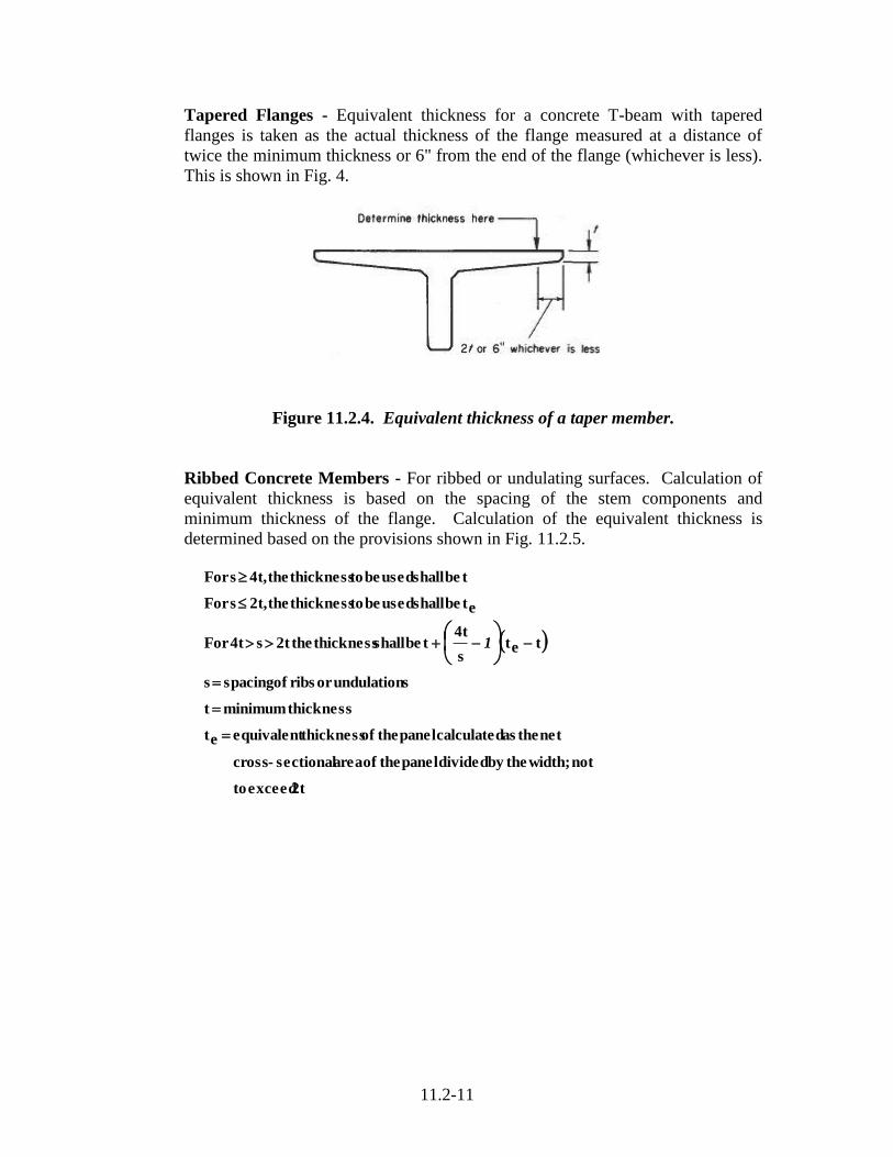
11.2-11
Tapered Flanges - Equivalent thickness for a concrete T-beam with tapered
flanges is taken as the actual thickness of the flange measured at a distance of
twice the minimum thickness or 6" from the end of the flange (whichever is less).
This is shown in Fig. 4.
Figure 11.2.4. Equivalent thickness of a taper member.
Ribbed Concrete Members - For ribbed or undulating surfaces. Calculation of
equivalent thickness is based on the spacing of the stem components and
minimum thickness of the flange. Calculation of the equivalent thickness is
determined based on the provisions shown in Fig. 11.2.5.
2t exceed to
not width; the by divided panel the of area sectional-cross
net the as calculated panel the of thickness equivalent et
thickness minimum t
sundulationor ribs of spacing s
tets
4tt be shall thickness the2t s 4t For
et be shall used be to thickness the 2t, sFor
t be shall used be to thickness the 4t, sFor
1

11.2-12
Figure 11.2.5 Equivalent thickness of a ribbed or undulating section
Hollow-Core Concrete Planks - The equivalent thickness (teq) of hollow-core
planks is obtained by the equation
where Anet is the gross cross section (thickness X width) minus the area of cores.
This is shown in Fig 11.2.6.
Figure 11.2.6 Typical hollow-core concrete plank
width
At neteq

11.2-13
Structural End Point
Fire Resistance of Prestressed Concrete Floor Slab - As previously discussed
the fire endurance of floor and roof slabs is based on either the heat transmission
or structural failure end point. It is for this reason that code approved empirical
methods require both a minimum slab thickness to limit heat transmission and a
minimum amount of concrete cover to limit steel temperatures. As discussed
earlier, the fire endurance of reinforced or prestressed concrete slabs is dependent
upon several factors, such as type of aggregate in the concrete, concrete cover,
and restraint of thermal expansion.
The values for slabs shown in Table 11.2.3 represent minimum required slab
thickness and concrete cover requirements for reinforced or prestressed slabs for
various aggregate type concretes in restrained or unrestrained conditions. The
tabular fire endurances listed are based on examination of past ASTM E 119 test
results of slabs with similar cover, restraint conditions, and concrete aggregate
type. The specified cover for unrestrained assemblies will maintain steel
temperatures below the specified limits of 800 ºF for prestressing and 1100 ºF for
reinforcing steel.
Table 11.2.3. Minimum Slab and Concrete Cover in Inches for Listed Fire
Resistance of Reinforced Concrete Floors and Roofs1
A. Minimum Slab Thickness for Concrete Floors or Roofs
2
Concrete aggregate type
Minimum slab thickness (inches)
For fire-resistance rating
1 hr 1 ½ hr 2 hr 3 hr 4 hr
Siliceous
Carbonate
Sand-lightweight
Lightweight
3.5
3.2
2.7
2.5
4.3
4.0
3.3
3.1
5.0
4.6
3.8
3.6
6.2
5.7
4.6
4.4
7.0
6.6
5.4
5.1
B. Cover Thickness for Reinforced Concrete Floor or Roof Slabs
3
Concrete aggregate type
Thickness of cover (inches) for fire-resistance rating
Restrained3 Unrestraind
3
1 hr 1 ½ hr 2 hr 3 hr 1 hr 1 ½ hr 2 hr. 3 hr.
Siliceous
Carbonate
Sand-lightweight
Lightweight
3/4
3/4
3/4
3/4
3/4
3/4
3/4
3/4
3/4
3/4
3/4
3/4
3/4
3/4
3/4
3/4
3/4
3/4
3/4
3/4
3/4
3/4
3/4
3/4
1
3/4
3/4
3/4
1 ¼
1 ¼
1 ¼
1 ¼
C. Cover Thickness for Prestressed Concrete Floor or Roof Slabs
3
Concrete aggregate type
Thickness of cover (inches) for fire-resistance rating
Restrained3 Unrestraind
3
1 hr 1 ½ hr 2 hr 3 hr 1 hr 1 ½ hr 2 hr. 3 hr.
Siliceous
Carbonate
Sand-lightweight
Lightweight
3/4
3/4
3/4
3/4
3/4
3/4
3/4
3/4
3/4
3/4
3/4
3/4
3/4
3/4
3/4
3/4
1 1/3
1
1
1
1 ½
1/ ¾
1 ¾
1 ¾
1 ¾
1 3/8
1 ½
1 ½
2 3/8
2 ½
2
2

11.2-14
Thermal Expansion During Fires - The coefficient of thermal expansion is used
to predict thermally induced loads and curvatures in a structure. Thermal
expansion of concrete was measured at elevated temperatures (Fig. 11.2.7).
Figure 11.2.7. Thermal Expansion of Concrete (ACI 216, 1994)
During actual fires members may expand against restraining structure and may
cause structural damage. The influence of concrete properties on thrust fold is
based on experimental research by Issen, Gustaferro and Carlson (1970). The
experimental program consisted of 40 standard fire resistance test conducted by
the Portland Cement Association (PCA).
The following is from the “Best Practice Guidelines for Structural Fire
Resistance Design of Concrete and Steel Buildings” (Multihazard Mitigation
Council-National Institute of Building Sciences, March 8, 2005):
“The first 25 tests were conducted to provide a set of reference tests that could be
used to obtain data to examine the accuracy of predictions from the analytical
method. The 25 tests included 13 normalweight (carbonate) and 12 lightweight
Double-T slabs that were 16 ft long. The specimens were both prestressed and
reinforced concrete designs. The expansion permitted in the tests ranged from
0.04 – 1.40 in. A diagram of a reference specimen is provided in Figure 11.2.8.

11.2-15
Figure 11.2.8. Reference Specimen (CRSI, 1980)
The maximum thrust measured from the reference specimens is plotted in the
graph in Figure 9. As expected, the thrust increased with a decrease in the
amount of expansion permitted.
In the next phase of the experimental program, 15 tests were conducted with
“correlation specimens”. These specimens used different geometries and
aggregates to observe differences in behavior. The analytical method developed
from the reference specimens was adapted with the data from the correlation
specimens for increased applicability.
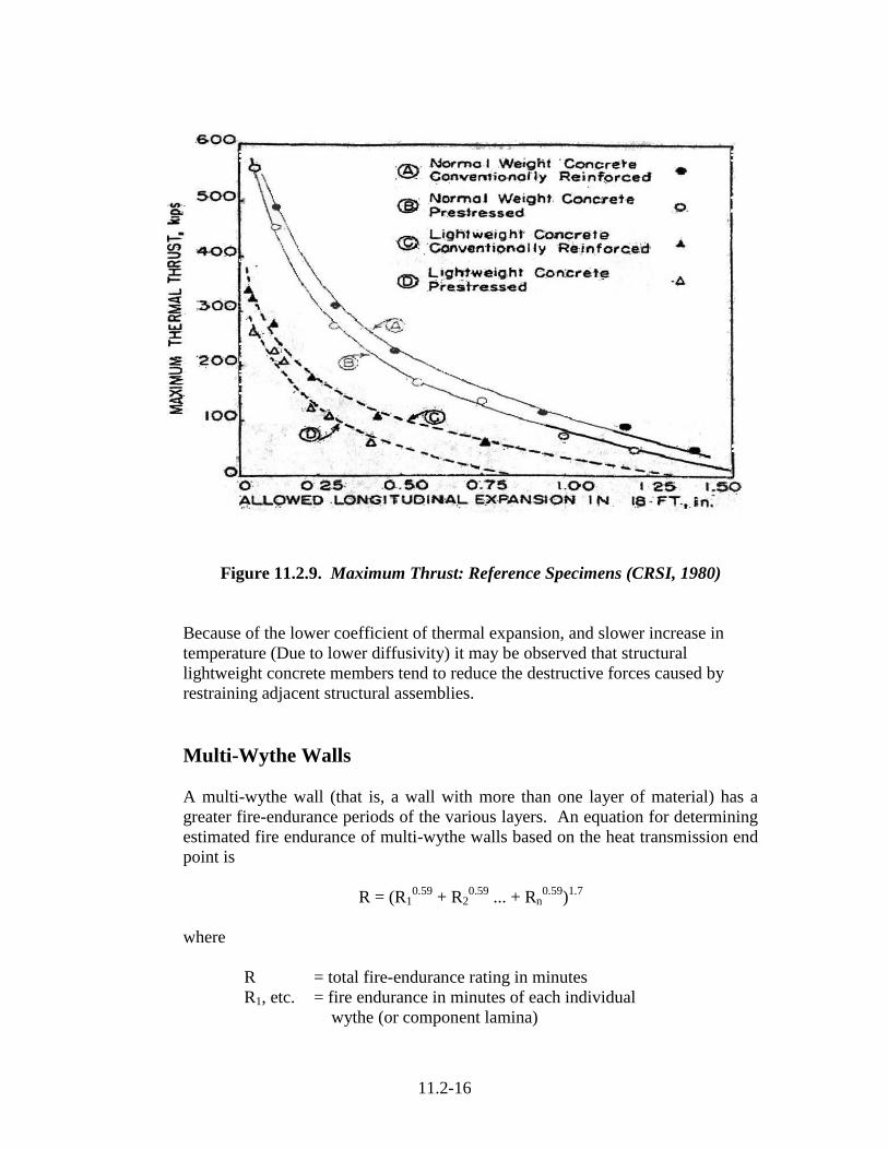
11.2-16
Figure 11.2.9. Maximum Thrust: Reference Specimens (CRSI, 1980)
Because of the lower coefficient of thermal expansion, and slower increase in
temperature (Due to lower diffusivity) it may be observed that structural
lightweight concrete members tend to reduce the destructive forces caused by
restraining adjacent structural assemblies.
Multi-Wythe Walls
A multi-wythe wall (that is, a wall with more than one layer of material) has a
greater fire-endurance periods of the various layers. An equation for determining
estimated fire endurance of multi-wythe walls based on the heat transmission end
point is
R = (R10.59
+ R20.59
... + Rn0.59
)1.7
where
R = total fire-endurance rating in minutes
R1, etc. = fire endurance in minutes of each individual
wythe (or component lamina)
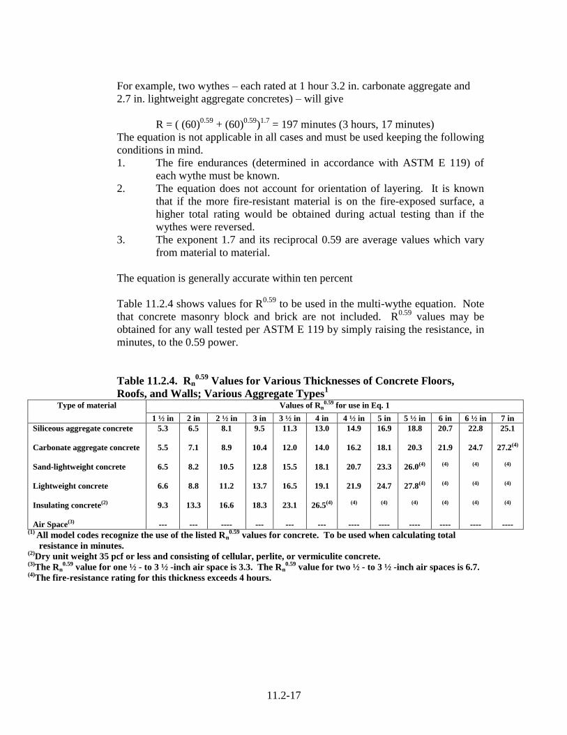
11.2-17
For example, two wythes – each rated at 1 hour 3.2 in. carbonate aggregate and
2.7 in. lightweight aggregate concretes) – will give
R = ( (60)0.59
+ (60)0.59
)1.7
= 197 minutes (3 hours, 17 minutes)
The equation is not applicable in all cases and must be used keeping the following
conditions in mind.
1. The fire endurances (determined in accordance with ASTM E 119) of
each wythe must be known.
2. The equation does not account for orientation of layering. It is known
that if the more fire-resistant material is on the fire-exposed surface, a
higher total rating would be obtained during actual testing than if the
wythes were reversed.
3. The exponent 1.7 and its reciprocal 0.59 are average values which vary
from material to material.
The equation is generally accurate within ten percent
Table 11.2.4 shows values for R0.59
to be used in the multi-wythe equation. Note
that concrete masonry block and brick are not included. R0.59
values may be
obtained for any wall tested per ASTM E 119 by simply raising the resistance, in
minutes, to the 0.59 power.
Table 11.2.4. Rn0.59
Values for Various Thicknesses of Concrete Floors,
Roofs, and Walls; Various Aggregate Types1
Type of material Values of Rn0.59 for use in Eq. 1
1 ½ in 2 in 2 ½ in 3 in 3 ½ in 4 in 4 ½ in 5 in 5 ½ in 6 in 6 ½ in 7 in
Siliceous aggregate concrete
Carbonate aggregate concrete
Sand-lightweight concrete
Lightweight concrete
Insulating concrete(2)
Air Space(3)
5.3
5.5
6.5
6.6
9.3
---
6.5
7.1
8.2
8.8
13.3
---
8.1
8.9
10.5
11.2
16.6
----
9.5
10.4
12.8
13.7
18.3
---
11.3
12.0
15.5
16.5
23.1
---
13.0
14.0
18.1
19.1
26.5(4)
---
14.9
16.2
20.7
21.9
(4)
----
16.9
18.1
23.3
24.7
(4)
----
18.8
20.3
26.0(4)
27.8(4)
(4)
----
20.7
21.9
(4)
(4)
(4)
----
22.8
24.7
(4)
(4)
(4)
----
25.1
27.2(4)
(4)
(4)
(4)
---- (1)
All model codes recognize the use of the listed Rn0.59
values for concrete. To be used when calculating total
resistance in minutes. (2)
Dry unit weight 35 pcf or less and consisting of cellular, perlite, or vermiculite concrete. (3)
The Rn0.59
value for one ½ - to 3 ½ -inch air space is 3.3. The Rn0.59
value for two ½ - to 3 ½ -inch air spaces is 6.7. (4)
The fire-resistance rating for this thickness exceeds 4 hours.

11.2-18
Fire Resistance of Concrete Masonry Walls
Concrete masonry units are available in nominal thicknesses of 2, 3, 4, 6, 8, 10
and 12 inch with varying percentages of solid area. The equivalent thickness for
hollow block can be calculated using a procedure similar to that for hollow-core
slabs. The percent of solids in any given masonry unit can be obtained from the
manufacturer or calculated. Once equivalent thickness is known, the fire
resistance rating of masonry walls can be determined. If 100% solid flat-sided
concrete masonry units are used, the equivalent thickness is the actual thickness.
The equivalent thickness of concrete masonry assemblies (Fig. 10), Teq shall be
computed as the sum of the equivalent thickness of the concrete masonry unit, Te
as determined by Tef, plus the equivalent thickness of finishes, Tef, determined in
accordance with:
Tea = Te + Te\f
Te = Vn / LH = equivalent thickness of concrete masonry unit, in. where
Vn = net volume of masonry unit, in.³
L= specified length of masonry unit, in.
H= specified height of masonry unit, in.
Ungrouted or partially grouted construction - Te shall be the value obtained for
the concrete masonry unit determined in accordance with ASTM C 140.
Solid grouted construction – The equivalent thickness, Te of solid grouted
concrete masonry units is the actual thickness of the unit.
Air spaces and cells filled with loose fill material – The equivalent thickness of
completely filled hollow concrete masonry is the actual thickness of the unit when
loose ordinary fill materials that meet ASTM C 33 requirements; lightweight
aggregates that comply with ASTM C 331; or perlite or vermiculite meeting the
requirements of ASTM C 549 and C 516, respectively.
The minimum equivalent thickness of various types of plain or reinforced
concrete masonry bearing or nonbearing walls required to provide fire resistance
ratings of 1 to 4 hour shall conform to Table 11.2.4. For examples of the fire
resistance ratings of typical lightweight aggregate CMU’s see Table 11.2.4.
“Equivalent Solid Thickness” is the average thickness of the solid material in the
unit, and is used as a criteria for fire resistance. We can compute Equivalent
Solid Thickness by this formula. If Ps equals percent solid volume, T equals
actual width of unit, then equivalent thickness,
100. .
TxPsTHEQ
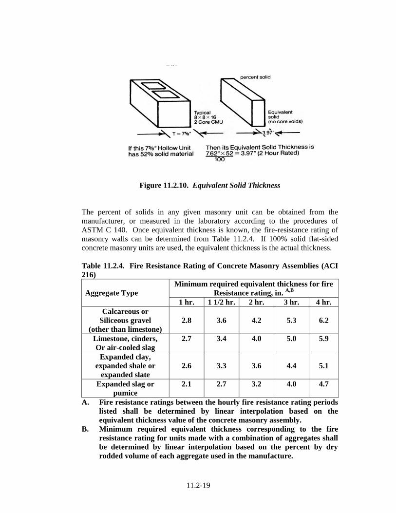
11.2-19
Figure 11.2.10. Equivalent Solid Thickness
The percent of solids in any given masonry unit can be obtained from the
manufacturer, or measured in the laboratory according to the procedures of
ASTM C 140. Once equivalent thickness is known, the fire-resistance rating of
masonry walls can be determined from Table 11.2.4. If 100% solid flat-sided
concrete masonry units are used, the equivalent thickness is the actual thickness.
Table 11.2.4. Fire Resistance Rating of Concrete Masonry Assemblies (ACI
216)
Aggregate Type
Minimum required equivalent thickness for fire
Resistance rating, in. A,B
1 hr. 1 1/2 hr. 2 hr. 3 hr. 4 hr.
Calcareous or
Siliceous gravel
(other than limestone)
2.8
3.6
4.2
5.3
6.2
Limestone, cinders,
Or air-cooled slag
2.7 3.4 4.0 5.0 5.9
Expanded clay,
expanded shale or
expanded slate
2.6
3.3
3.6
4.4
5.1
Expanded slag or
pumice
2.1 2.7 3.2 4.0 4.7
A. Fire resistance ratings between the hourly fire resistance rating periods
listed shall be determined by linear interpolation based on the
equivalent thickness value of the concrete masonry assembly.
B. Minimum required equivalent thickness corresponding to the fire
resistance rating for units made with a combination of aggregates shall
be determined by linear interpolation based on the percent by dry
rodded volume of each aggregate used in the manufacture.

11.2-20
Analysis of the Validity of the Fire Resistance Ratings Contained in Table
11.2.4 - A significant number of the required equivalent thickness values shown
in Table 11.2.4 are fundamentally incorrect. To a large degree the ratings are
based upon the tests conducted in the 1930’s, wherein the walls tested were not in
keeping with the requirements of ASTM E 119. Lack of conformance with the
procedure of ASTM E 119 included:
Some walls were tested too early with units that contained excessive
moisture approximately 2 months old and therefore having relative
humidity’s greater than the maximum allowed by E 119. Because water
boils at 212ºF, the temperature on the unexposed side will not rise above
212ºF until all the moisture is boiled off. As shown in Fig. 11 this process
significantly extends the “steaming zone” allowing the wall to have
unsupportable long fire endurance in violations of the standard procedures
of E 119.
Figure 11.2.11 Effect of extension of fire endurance due to extension of
“steaming zone” due to CMU RH > 75% (Nov. ASTM E 119)

11.2-21
Table 11.2.5. Estimate Rating – Expanded Slag Rating
Hours
American Insurance Association
ACI 216.1*
Table 3.1
NCMA
Sponsored
Tests ASTM
E 119 Omega
point 1990
Estimated
ratings* not
tested in
accordance to
ASTM E 119
Tested in
accordance with
ASTM E 119
4 4.7 5.3 4.7 5.7
3 4.0 4.78 4.0 -----
2 3.2 4.13 3.2 3.8
1 2.1 ----- 2.1 ----
*Tests not in compliance with ASTM E 119, CMU’s not in compliance with
ASTM C 90 (AIA Ref 42).
Additionally all the walls tested did not meet the size requirements of ASTM E
119. Finally, many of the walls tested were composed of CMU’s that did not
meet the requirements of ASTM C 90 “Standard Specification for Load Bearing
Concrete Masonry Units”.
Consider for example the Tables 11.2.6 and 11.2.7 shown that were part of the
fire endurance ratings data produced by the American Insurance Association and
widely used in the past by the designer. Note that comparison between the
“Estimated Ratings Table” and the table based upon full scale ASTM E 119 for
CMU’s based on an aggregate type that includes expanded slag or pumice.
Table 6 comparing the results of tests sponsored by NCMA in 1990 with the fire
ratings value in Table 3.1 of ACI 216 further demonstrates the inadequacies of
table 3.1. In all other sections of ACI 216 (Fire resistance of slabs, column
protected by CMU and brick masonry) the protection is related to the density of
the concrete, CMU’s and brick Table 3.1 divides protective material resistance by
aggregate type only, a technically unsupported procedure.

11.2-22
FULL SCALE ASTM E 119 FIRE TESTS ON CMU’S - Shown in Table
11.2.7 are the results of tests on CMU’s made with ESCS aggregate.
Table 11.2.6. Fire Resistance Rating – Typical Lightweight Aggregate
Masonry Units using ESCS aggregate.
Size Type %
Solid
Equivalen
Thickness
Fire
Resistance
Rating Hours
4x8x16 2 core 65 2.36 1
4x8x16 Solid 100 3.63 2
6x8x16 2 core 49 2.76 1
6x8x16 3 core 69 3.87 2
6x8x16 3 core 89 5.01 4
8x8x16 2 core 52 3.97 2
8x8x16 75% solid 75 5.72 4
8x8x16 2 core 58 4.40 3
12x8x16 2 core 49 5.70 4
12x8x16 75% solid 75 8.72 4
6" Backup 61% solid, unplastered faced with 2 1/4" brick 4
Equivalent thickness shown are representative of typical commercial units.
Wear of mold parts, or differing geometry may result in small variation.
Note: 8", 10", and 12" units shown conform to UL 618, 4" and 6" units
conform to National Bureau of Standards and National Research Council
full scale fire tests. The reports of these wall tests are available from the
Expanded Shale, Clay and Slate Institute (ESCSI).
Table 11.2.7 compares fire resistance rating of CMU as reported in ACI 216.1,
NCMA Omega Point test and UL 618.

11.2-23
Table 11.2.7 ACI 216.1 Fire Resistance Rating of Concrete Masonry
Assembly Compared to Underwriters UL 618 and the Results of Tests on
CMU Walls Sponsored by NCMA at Omega Point Laboratories
Eq. Th. Fire Endurance Requirements 2 Hours 4 Hours
RATINGS (Reference) ACI
216.1
NCMA
Omega
UL 618 ACI
216.1
NCMA
Omega
UL 618
TIME 1997 1990 1998 1997 1990 1998
AGGREGATE TYPE
Expanded Slag 3.2 3.83 4.10 4.7 5.67 5.3
Expanded Slag blended with Sand 4.07 6.07
Expanded Slag blended Limestone 4.12 5.82
Pumice 3.2 3.62 4.7 4.83 4.4
Pumice blended with sand 3.87 5.42
ESCSI 3.6 3.6 5.1 5.1
Limestone, cinders, unexpanded
slag
4.0 4.34 5.9 6.39
Calcareous 4.2 6.2
(Limestone/S&G) 4.34 6.54
Siliceous 4.2 4.2 6.2 6.45
Natural or By-Product
W or W/O sand (700 psi)
4.2
Natural or By-Product
W or W/O sand (1800 psi)
6.5

11.2-24
Field Performance of Lightweight Concrete Masonry Units
Lightweight concrete masonry walls have an outstanding record of exceeding all
the requirements of the fire testing standard, ASTM E 119 tests (Fig 11.2.12).
Figure 11.2.12. 12" LWCMU Wall Passing Hose
Stream Pressure After 4 hour Fire Test.
The LWC masonry unit wall successfully endured the full 4 hour fire test with
almost no visible cracking, without any spalls and with insignificant lateral
bowing. Immediately after reaching the fire test time limit the wall was extracted
from the furnace and exposed to the standard ASTM E 119 hose stream test.
Despite the force of the high pressure hose stream and the intense thermal shock
developed by the cold water impacting on the fiery hot exposed face that had
experienced 4 hours of gas flames at temperatures approaching 2000ºF, there was
no damage to the wall.
On the following day, the wall was deliberately demolished by a fork lift for
disposal. To demonstrate the remarkable inherent structural integrity, three fire
exposed LW concrete masonry units were salvaged from the rubble of the
collapsed wall and taken to an independent testing laboratory for standard
compression tests. All three units failed in compression on the fire tested side
with average net strengths approaching 1400 psi. Developing such high residual
compression strengths in a standard test, despite non-uniform loading developed

11.2-25
due to the non-homogeneous concrete block properties (exposed versus
unexposed sides) is outstanding performance. After enduring 4 hours of high
temperature fire exposure, despite the thermal shock of the hose stream test, and
after being demolished by a fork lift, these LWCM units still had sufficient
capacity to maintain wall integrity to protect fire fighters. This remarkable
performance confirms the fact that a commercially available LWCMU wall can
function both as a structural and thermally insulating fire wall barrier to contain
fire spread (See Fig. 11.2.13).
Figure 11.2.13. LWCMU Fire Wall Meets Expectations!
Proven Performance in Actual Fires.
Safety - Safety! That’s what it’s about. Just how long can a fire be contained to
save lives? How long can a fire be contained to give firemen a chance to save the
building? The answer to these questions is related to the fire resistance and
structural stability of walls, columns, floors, and other building members exposed
to the fire.
When tested side by side in actual fires in real world structures, concrete masonry
unit walls have outperformed other fire resistant, non-masonry wall systems. The
photographs in Fig. 11.2.13 and 11.2.14 shows the aftermath of a catastrophic fire

11.2-26
to an essentially completed, but fortunately unoccupied, retirement complex in
Kentucky. The fire destroyed 120 units and caused 6 million dollars in damage.
The flames spread unchecked from end to end of the structure without any fuel
load other than the construction materials used. A nearby hospital had to be
evacuated due to intense radiant heat temperatures sufficient to buckle glass. The
only assembly remaining intact in the path of the fire was the elevator shaft,
constructed just prior to the fire with lightweight aggregate concrete masonry
units (Fig. 12).
When the complex was rebuilt, the decision to use lightweight aggregate concrete
masonry units to replace alternate containment materials in other parts of the
project was based on a solid performance record under conditions significantly
more severe than laboratory test.
Figure 11.2.14. The only remaining assembly is the
Elevator shaft constructed with lightweight
Aggregate concrete masonry units.
11.3-1
11.3 Acoustical Resistance of Walls of Lightweight Concrete and
Lightweight Concrete Masonry
Resistance to Transmission of Airborne Sound
Introduction - The control of sound in rooms of buildings may be classified with
respect to the origin of the sound-namely, sounds originating within the room and
sounds originating outside the room. Efficient and economical control of sound is
dependent not only upon its origin, but also upon the design of the enclosure and
type of occupancy.
For reduction of sound originating within a room, the sound absorption qualities
of the walls, ceiling and flooring, as well as furnishings, are important. The type
and use of the room affords the architect latitude in the selection of sound
absorption materials for elements of the room. Enclosures with high ceilings and
large expanse of wall areas, as in gymnasiums and churches, might utilize sound
absorbing textured masonry walls as an economical solution. On the other hand,
for enclosures with relatively low ceilings, and rather small exposed wall areas, as
in offices and classrooms, the use of acoustical ceilings, floor coverings, and
interior furnishings might be the more effective solution.
This section is concerned primarily with utilizing concrete and concrete masonry
to reduce the sources of sound transmitted through building partitions from
sources outside of rooms. These sounds are transmitted as solid-borne, as well as
air-borne, noise. For example, a bare concrete floor transmits the sound of
footsteps between rooms, the sound traveling through the rigid concrete slab.
Solid-borne impact sound should be suppressed at the source. A concrete floor
for example, should be covered with a resilient material, to minimize the amount
of solid-borne sound transmission.
Air-borne sound may be effectively reduced by barriers such as concrete masonry
partitions. Obviously, attention should be given to doors and their closures, as
well as connections of the walls to the ceilings and floors. Too often the
effectiveness of a concrete masonry partition, which should provide satisfactory
acoustical isolation, is unnecessarily lost, by failure to take into account the other
important factors that are involved, such as continuing the partition to the
structural ceiling. Also, cutting of continuous holes through the wall for ducts,
and electrical outlets should be avoided.
The Energy of Sound - Sound energy is measured in decibels. The decibel is a
convenient unit because it is approximately the smallest change in energy that the
ear can detect. The following table 11.3.1. Of sound intensities will aid in an
understanding of decibel values.
11.3-2
Table 11.3.1. Representative Sound Levels
Loudness Decibels Sound
Deafening
110-150
Jet plane takeoff
Siren at 100 ft (30 m)
Thunder-sonic boom
Hard rock band
Very Loud 90-100 Power lawn mower
Pneumatic jackhammer
Loud 70-80 Noisy office
Average radio
Moderate 50-60 Normal conversation
Average home
Faint 30-40 Private office
Quite home
Very Faint 3-20 Whisper at 4 ft (1.2 m)
Normal breathing TEK 13-1A ©2000 National Concrete Masonry Association (replaces TEK 13-1)
Sound Transmission Resistance of Concrete Masonry - Sound is transmitted
through most walls and floors by setting the entire structure into vibration. This
vibration generates new sound waves of reduced intensity on the other side. The
passage of sound into one room of a building from a source located in another
room or outside the building is termed “sound transmission”.
Transmission loss is a measure of the effectiveness of a wall, floor, door or other
barrier in restricting the passage of sound. The transmission loss varies with
frequency of the sound and the loss is usually greater with higher frequencies.
Sound transmission loss measurements are conducted in accordance with
American Society for Testing and Materials ASTM E 90 “Standard Test Method
for Laboratory Measurement of Airborne Sound Transmission Loss of Building
Partitions”. A concrete or concrete masonry wall eleven (11) feet (3.35 m) wide
and nine (9) feet (2.74 m) high mounted on a movable base is rolled between two
isolated reverberation rooms (Fig. 11.3.1 & 11.2.2). Measurements are made at
16 frequencies in 1/3-octave bands, from 125 to 4000 cycles per second, (cps)
(generally called Hertz (Hz). The unit of measure of sound transmission loss is
the decibel (dB). The higher the transmission loss of a wall the better it functions
as a barrier to the passage of unwanted noise.
Lightweight concrete masonry units produced under strict laboratory supervision
and inspection were made and shipped to Kowaris Acoustical Laboratories where
the blocks were made into movable wall panels of various thicknesses with a wall
area of 99 sq. ft. These panels rolled between two isolated reverberations rooms,
where measurements of sound transmission loss were made.

11.3-3
Figure 11.3.1. Testing for sound transmission resistance of
lightweight concrete masonry units by procedures
of ASTM E 90.
Sound transmission loss tests were conducted in accordance with the American
Society for Testing and Materials designation E 90 on a lightweight concrete
masonry unit wall 11 feet wide and 9 feet high mounted on a movable base. The
lightweight concrete masonry unit wall was rolled between two isolated
reverberation rooms. Measurements were made at 16 frequencies in 1/3-octave
hands, from 125 to 4000 cps.
Figure 11.3.2. Laboratory set-up for measurements
of sound transmission loss.

11.3-4
Determination of Sound Transmission Class (STC) - Sound transmission class
(STC) provides an estimate of the performance of a wall in certain common sound
insulation applications.
The STC of a wall is determined by comparing plotted transmission loss values to
a standard contour. Sound transmission loss (STL) is the decrease or attenuation
in sound energy, in dB, of airborne sound as it passes through a wall. Although
STC is a convenient index of transmission loss, it may be necessary in some cases
to study the sound transmission loss data across a range of frequencies. This may
be desirable in a case where the main source of noise is of one known frequency.
In this case, the STL curve is checked to ensure there is not a “hole”, or low STL
value, at the particular frequency of interest.
To determine STC, the standard curve is superimposed over a plot of the STL
curve obtained by test (Figure 11.3.3) and shifted upward or downward relative to
the test curve until some of the measured transmission loss values fall below those
of the standard STC contour and the following conditions are fulfilled:
1. The sum of the deficiencies (deviations below the standard contour are
not greater than 32 dB, and
2. The maximum deficiency at a single test point is not greater than 8 dB.
When the contour is adjusted to the highest value that meets the above criteria, the
sound transmission class is taken to be the transmission loss value read from the
standard contour at the 500 Hz frequency line. For example, the STC for the data
plotted in Figure 11.3.3 is 45.
Figure 11.3.3. Frequency in cycles per second.

11.3-5
Results of laboratory tests on walls of lightweight concrete masonry units.
Many walls constructed with lightweight concrete masonry units produced with
expanded shale, clay or slate by the rotary kiln method has been tested. Tests of
these various walls are listed in Table 11.3.2.
Table 11.3.2. Test results sound transmission class (STC) for lightweight
concrete masonry walls MASONRY WALL THICKNESS 4 inch 6 inch 8 inch 12 inch
Plain 40 44 45
Painted 41 45 46 50
Wall Board attached one side 47 49 56
Plastered 50 50 51
Cores filled with insulation - - 51
COMPOSITE*-Cavity*-Grouted*
8”
4” Block plus 4” Concrete Brick plain 51
plastered on
block surface
53
½” gyp. Board
on block face
56
10”CAVITY
4” Block-2” Cavity-4” Concrete Brick plain 54
½” plastered on
block
57
½” gyp on
block
59
All cells grouted 48
½” plaster both
sides
56
½” gyp. both
sides
60
*The National Concrete Masonry Association was sponsor of the composite, cavity & grouted walls.
Calculated STC Values – Analysis of the results of sound transmission loss tests
on a wide range of concrete masonry walls yield the following equation:
STC = 0.18W + 40
Where W = wall weight in psf
The equation is applicable to uncoated fine- or medium-textured concrete
masonry. Coarse-textured units, however, may allow airborne sound to enter the
wall, and therefore require a surface treatment to seal at least one side of the wall.
Coatings of acrylic, alkyd latex, or cement-based paint, or of plaster are
specifically called for in The Masonry Society Standard 0302, although other
coatings that effectively seal the surface are also acceptable. The equation above
also assumes the following:
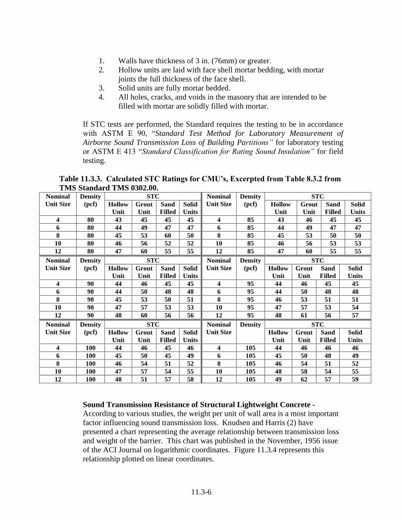
11.3-6
1. Walls have thickness of 3 in. (76mm) or greater.
2. Hollow units are laid with face shell mortar bedding, with mortar
joints the full thickness of the face shell.
3. Solid units are fully mortar bedded.
4. All holes, cracks, and voids in the masonry that are intended to be
filled with mortar are solidly filled with mortar.
If STC tests are performed, the Standard requires the testing to be in accordance
with ASTM E 90, “Standard Test Method for Laboratory Measurement of
Airborne Sound Transmission Loss of Building Partitions” for laboratory testing
or ASTM E 413 “Standard Classification for Rating Sound Insulation” for field
testing.
Table 11.3.3. Calculated STC Ratings for CMU’s, Excerpted from Table 8.3.2 from
TMS Standard TMS 0302.00. Nominal
Unit Size
Density
(pcf)
STC Nominal
Unit Size
Density
(pcf)
STC
Hollow
Unit
Grout
Unit
Sand
Filled
Solid
Units
Hollow
Unit
Grout
Unit
Sand
Filled
Solid
Units
4 80 43 45 45 45 4 85 43 46 45 45
6 80 44 49 47 47 6 85 44 49 47 47
8 80 45 53 60 50 8 85 45 53 50 50
10 80 46 56 52 52 10 85 46 56 53 53
12 80 47 60 55 55 12 85 47 60 55 55
Nominal
Unit Size
Density
(pcf)
STC Nominal
Unit Size
Density
(pcf)
STC
Hollow
Unit
Grout
Unit
Sand
Filled
Solid
Units
Hollow
Unit
Grout
Unit
Sand
Filled
Solid
Units
4 90 44 46 45 45 4 95 44 46 45 45
6 90 44 50 48 48 6 95 44 50 48 48
8 90 45 53 50 51 8 95 46 53 51 51
10 90 47 57 53 53 10 95 47 57 53 54
12 90 48 60 56 56 12 95 48 61 56 57
Nominal
Unit Size
Density
(pcf)
STC Nominal
Unit Size
Density STC
Hollow
Unit
Grout
Unit
Sand
Filled
Solid
Units
Hollow
Unit
Grout
Unit
Sand
Filled
Solid
Units
4 100 44 46 45 46 4 105 44 46 46 46
6 100 45 50 45 49 6 105 45 50 48 49
8 100 46 54 51 52 8 105 46 54 51 52
10 100 47 57 54 55 10 105 48 58 54 55
12 100 48 51 57 58 12 105 49 62 57 59
Sound Transmission Resistance of Structural Lightweight Concrete -
According to various studies, the weight per unit of wall area is a most important
factor influencing sound transmission loss. Knudsen and Harris (2) have
presented a chart representing the average relationship between transmission loss
and weight of the barrier. This chart was published in the November, 1956 issue
of the ACI Journal on logarithmic coordinates. Figure 11.3.4 represents this
relationship plotted on linear coordinates.

11.3-7
Figure 11.3.4 presents rather clearly the decreasing value of wall weight in
effecting sound transmission loss. It will be noticed that whereas the first 15 lbs.
per square foot of wall area furnish a loss of 40 decibels, the next 15 lbs. per
square foot increase the loss only 5 decibels.
Results of tests conducted on cast-in-place structural lightweight concrete are
superimposed on the Knudsen and Harris curve shown in Fig. 11.3.4. Test walls
were constructed with a nominal 3000 psi concrete with air 4.5% and a fresh
density of 116 pcf. The tests confirm the weight vs. sound transmission loss
curve (Table 11.3.4).
Table 11.3.4. Comparison of STC vs. Weight
Wall (in.) Weight (psf) Test Results MH Curve TMS 302-00
4 37 46 45 47
8 74 52 50 53
Figure 11.3.4. Sound Transmission Loss as a Function of Wall Weight
Sound Absorption of Concrete Masonry Walls
Introduction - Sound absorption control deals with the reduction and control of
sound emanating from a source within the room. Control is dependent on the
shape, as well as the efficiency, of the many surfaces in the room in absorbing
(i.e., not reflecting) sound waves.
The study of sound conditioning and acoustical control is highly specialized field,
and for a thorough and accurate solution, particularly of special problems,

11.3-8
authorities on the subject and more detailed manuals should be consulted. This
section will serve as an introduction to some of the principles involved.
Principal of Control - Sound waves created by voices, equipment, and other
sources, radiate in all directions in a room until they strike a surface, such as a
wall, ceiling, floor, or furnishings. There the energy of the sound wave is partly
absorbed and partly reflected, the extent of each depending on the nature of the
surface it strikes. Reduction of the amount of sound reflected, therefore, is
essentially a matter of selection of materials for walls, floor, ceiling, and
furnishings which will absorb the desired degree of sound. In the control of
sound where a speaker or music is to be heard, such as in a church or auditorium,
reverberation time in the room should also be considered.
Absorption Control - The following three terms are introduced to define and
evaluate sound absorption: Sound Absorption Coefficient, Sabin, and Noise
Reduction Coefficient.
The Sound Absorption Coefficient is a measure of the proportion of the sound
striking a surface which is absorbed by that surface, and is usually given for a
particular frequency. Thus, a surface which would absorb 100% of the incident
sound would have a Sound Absorption Coefficient of 1.00, while a surface which
absorbs 45% of the sound, and reflects 55% of it, would have a Sound Absorption
Coefficient of 0.45. The Sound Absorption Coefficient usually varies with each
frequency tested.
A Sabin is defined as the amount of sound absorbed by one square foot of surface
having a Sound Absorption Coefficient of 1.00. The number of Sabins
(Absorption Units) of a given area is then the product of the area and the Sound
Absorption Coefficient. A 100 sq. ft. area of a surface with a Sound Absorption
Coefficient of 0.25 furnishes 25 Sabins (Absorption Units).
Most materials are tested at frequencies from 125 to 4000 cycles per second (cps)
in octave steps. The Noise Reduction Coefficient is the average of the Sound
Absorption Coefficient at 250, 500, 1000 and 2000 cps in octave steps. Table 1
lists approximate values of the Noise Reduction Coefficients of numerous
materials.
Texture - The Noise Reduction Coefficient of a surface is, to a large degree,
dependent on the porosity of the material and the texture of the surface. For
example, a sheet of painted fiberboard with its relatively smooth paint covering
would be expected to reflect a major portion of sound striking it, thereby
furnishing low sound absorption. On the other hand, if the surface were
punctured with a number of holes, sound could then penetrate the porous core and
be dissipated, thus appreciable increasing its sound absorption.

11.3-9
Concrete masonry produced with ESCS offers an extremely strong material with
countless minute pores and void spaces due to the modern processes of aggregate
and block manufacture. These pores and void spaces naturally appear on the
surface of the unit, thereby permitting sound waves to enter the unit and be
dissipated within the material, this characteristic results in good sound absorbing
properties, when compared to ordinary concrete surfaces.
Painting the concrete masonry will tend to seal the surface, reducing the sound
absorption. Tests indicate the extent of sealing depends upon the type of paint
and method of applications (See Table 11.3.5).
Table 11.3.5 Noise Reduction Coefficients MATERIAL APPROX.
N.R.C.
Expanded Shale Block,
Medium Texture, unpainted
Heavy Aggregate Block
Medium Texture, unpainted
0.45
0.27
Increase 10% for Coarse
Texture
Decrease 10% for Fine Texture
Increase 5% for Coarse Texture
Decrease 5% for Fine Texture
REDUCTIONS OF ABOVE FOR PAINTED BLOCK
PAINT TYPE APPLICATION ONE
COAT
TWO
COATS
THREE
COATS
Any
Oil Base
Latex or Resin Base
Cement Base
Spray
Brushed
Brushed
Brushed
10%
20
30
60
20%
55
55
90
70%
75
90
__
MATERIAL N.R.C. MATERIAL N.R.C.
Brick wall-unpainted
Brick wall-painted
Floors
Concrete or terrazzo
Wood
Linoleum, asphalt, rubber or cork
Tile on concrete
Glass
Marble or glaze tile
Plaster, gypsum or lime, smooth
Finish on tile or brick
Same on lath
Plaster, gypsum or lime, rough
Finish on lath
Plaster, acoustical
Wood Paneling
Acoustical Ceiling Tile
Carpet, heavy, on concrete
Carpet, heavy, hairfelt underlay
.05
.02
.02
.03
.03-.08
.02
.01
.04
.04
.05
.21
.06
.55-.85
.45
.70
Fabrics
Light, 10 oz. Per sq. yd.
hung straight
Medium, 14 oz. Per sq. yd.
draped to half area
Heavy, 18 oz. Per sq. yd.
draped to half area
.20
.57
.63
Note: Adapted from ESCSI Information Sheet 3430.2 “Sound Absorption of Concrete
Masonry Walls”
11.3-10
Reverberation - Reverberation is the persistence of sound within an enclosed
space after the source of sound has been cut off. Its effect on hearing is to
prolong syllables in speech or tones in music which, if not in the right range,
make hearing difficult and irritating.
Reverberation time is defined as the time in seconds for the intensity level to fall
60 decibels. The factors which affect reverberation time are (1) the volume of the
room and (2), the sound absorbing properties of the room’s surfaces.
In small rooms, such as offices, reverberation generally is not the major factor. In
assembly areas where speech or music is to be heard, as in churches and
auditoriums, an investigation of reverberation time is necessary.
Reverberation time may be computed by the .05V formula developed by Prof.
W.C. Sabine:
T=reverberation time
V=volume of the room in cubic feet
a=absorption of the surfaces in Sabins
The desirable reverberation times for hearing may be taken from the chart in Fig.
11.3.5. The shaded area on this chart represents acceptable reverberation times
for various room sizes. When treating rooms for speech or with public address
systems, the times should fall nearer the lower limit of tolerance. In churches or
rooms designed for music or without public address systems, the time selected
should fall nearer the upper limits.
Sound Absorption Calculations - Tabulated or tested values of the Sound
Absorption Coefficient, plus the concept of the Sabin (Absorption Unit) provide a
means of estimating the total sound absorbed in a room, and permit a choice of
materials to accomplish the desired value.
Experience of acoustical engineers has indicated that for noise reduction comfort,
the total number of Absorption Units in a room (exclusive of the absorption
provided by the occupants), should be between 20% and 50% of the total surface
area in square feet. The lower range is generally satisfactory for enclosures such
as offices and classrooms, whereas the upper range is desirable for such areas as
libraries. Where a speaker or music is to be heard by an audience, reverberation
time becomes the controlling factor in comfort design.
wherea
.T
050

11.3-11
Figure 11.3.5 Reverberations time-seconds.
The following example will serve to illustrate Sound Absorption calculations.
An office 15 x 25 ft. with 9-foot ceilings: medium textured concrete masonry
walls sprayed with two coats of latex base paint, asphalt tile floors, and acoustical
tile ceiling. Interior Surface Area-(15x25x2)+(30+50)x9=1,470 sq. ft.
1,470x20%=294, minimum number of Absorption Units desired for comfort.
1470 x 50% = 735, desirable number of Absorption units.
Absorption Units Calculations (See Table 1 for Noise Reduction Coefficients).
Floor 12x25 375 sq.ft.x0.05 = 19.0
Ceiling 15x25 375 sq.ft.x0.70 = 262.0
Window 6x4 25 sq.ft.x0.02 = 0.5
Door 6.5x4 26 sq.ft.x0.06 = 1.5
Walls (30+50)x9 720 sq.ft.
Masonry 720-(24+26) 670 sq.ft.x0.36* = 241.0
524.0
*LW cmu med. texture 0.45-(.2x.45)=0.36

11.3-12
Since the total Absorption Units are greater than the minimum required, 294, and
less than the maximum, 735, the office should be satisfactory.
References
1. “Less Noise-Better Hearing”, 6th
Edition, Hale J. Sabine, The Celotex
Corporation.
2. “Theory and use of Architectural Acoustical Materials”, 2nd
Edition,
Paul E. Sabine, Acoustical Material Association.
3. “Sound Reduction Properties of Concrete Masonry Walls”, 1955,
National Concrete Masonry Association.
4. “Sound Absorbing Value of Portland Cement Concrete”, by F.R. Watson
and Keron C. Morrical, ACI Journal, May-June 1936.
5. “Insulating Concrete”, by R.C. Valore, Jr., ACI Journal November,
1956.
Resistance to Impact Sound
Introduction - The increased noisiness of our environment has led to concern for
the isolation of impact noise. Footsteps, dropped toys and some appliances cause
impact noise. Isolation against impact noise provided by a given floor
construction is measured in accordance with ISO recommendation R 140-60.
This procedure utilizes a standard tapping machine that is placed in operation on a
test floor specimen, which forms a horizontal separation between two rooms, one
directly above the other. The transmitted impact sound is measured in 1/3-octave
bands over a frequency range of 100 to 3150 Hz in the receiving room below.
From the data collected a single figure rating, called Impact Insulation Class
(IIC), is derived in a prescribed manner from the values of the impact sound
pressure levels measured in the receiving room. The rating provides an estimate
of the impact sound insulating performance of a floor-ceiling assembly. Details
of the procedures are outlined in ASTM E-492.
Laboratory Testing Program - The Expanded Shale, Clay & Slate Institute
sponsored a test program at Riverbank Laboratories, Geneva, Illinois, to
determine the effect of the concrete density and Modulus of Elasticity on impact
sound transmission. Slab thicknesses of 5 inches and 10 inches were selected for
study. Three concretes designed to weigh approximately 95, 115, and 150
pounds per cubic foot were used so the weight per square foot of floor would
cover a broad range. The slabs were designed for a compressive strength of 3000-
psi (21 Mpa) and included reinforcement in keeping with flat plate design.
The impact Noise Reduction (INR) factors determined from the Riverbank
Laboratory tests have been converted to the current designation, Impact Insulation
Class (IIC), and are shown in Table 11.3.6.
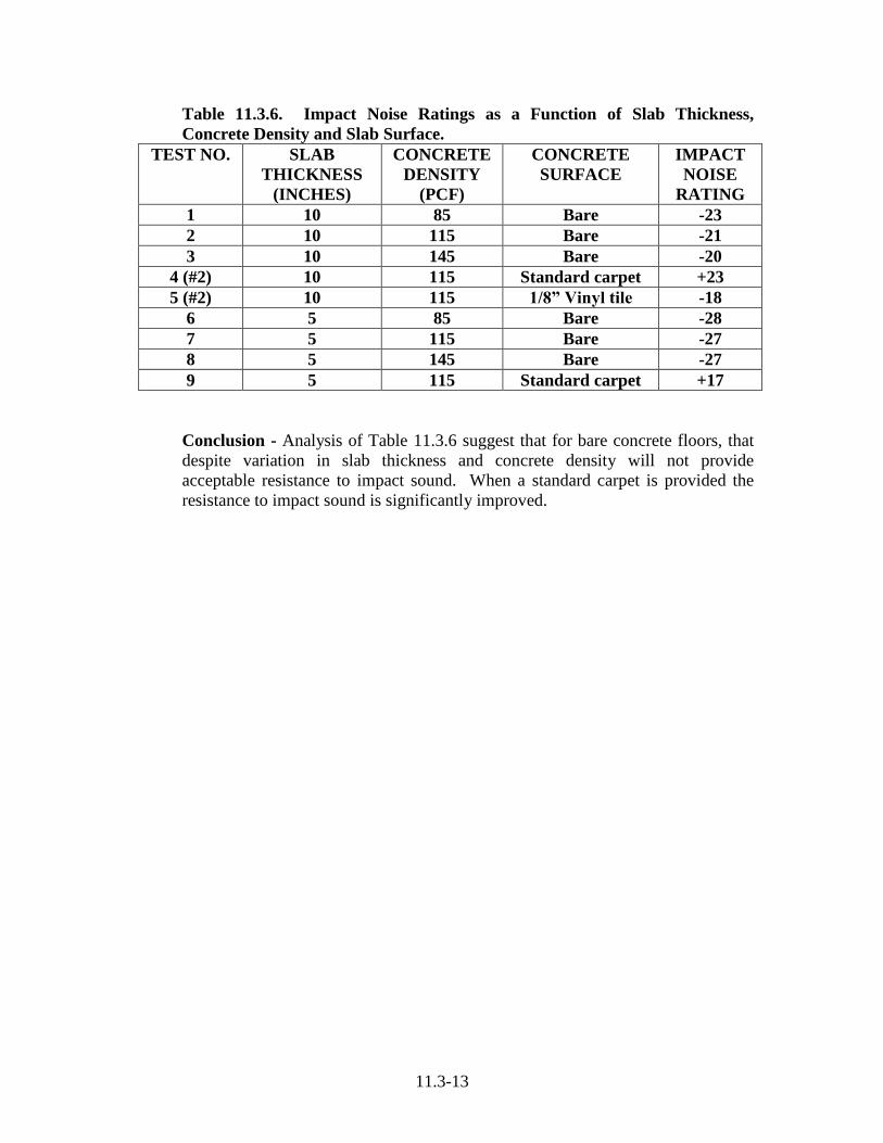
11.3-13
Table 11.3.6. Impact Noise Ratings as a Function of Slab Thickness,
Concrete Density and Slab Surface.
TEST NO. SLAB
THICKNESS
(INCHES)
CONCRETE
DENSITY
(PCF)
CONCRETE
SURFACE
IMPACT
NOISE
RATING
1 10 85 Bare -23
2 10 115 Bare -21
3 10 145 Bare -20
4 (#2) 10 115 Standard carpet +23
5 (#2) 10 115 1/8” Vinyl tile -18
6 5 85 Bare -28
7 5 115 Bare -27
8 5 145 Bare -27
9 5 115 Standard carpet +17
Conclusion - Analysis of Table 11.3.6 suggest that for bare concrete floors, that
despite variation in slab thickness and concrete density will not provide
acceptable resistance to impact sound. When a standard carpet is provided the
resistance to impact sound is significantly improved.

11.4-1
11.4 Resistance to the Environment of Lightweight Concrete and
Lightweight Concrete Masonry
Dimension Stability
General - Masonry is undeniably the most enduring of all construction materials,
and yet paradoxically, it is never quiescent. As with all construction materials,
the assemblage of units and mortar as we know as masonry is an eternal state of
movement caused by the inevitable changes in temperature, moisture and
chemistry. Additionally, as masonry is usually connected to other structural
members, the differential movements between the various building elements must
also be accommodated. An attitude of accommodation to movement is essential
as the forces of nature cannot be resisted without causing distress.
This section will briefly account for the factors causing volumetric changes in
units and elements and then suggest practical methods of accommodating these
movements. Frequently in masonry construction there are conflicting desires to
provide isolation of individual building elements and yet maintain continuity of
the structure as a whole. These considerations are mutually exclusive and a
design professional must apply judgment in trade-offs between these
considerations and promote the optimized structure. Comprehensive information
and recommendations on masonry movements and crack control is available from
The National Concrete Masonry Association (NCMA) including TEK 10-1A, 2B,
3 and 4.
Of the numerous considerations involved in the analysis of movements in joints
there are a few global views of masonry that are especially useful. First, any
attempt to resist the forces of nature is unlikely to succeed. In general, free
unimpeded movement of units and elements will not cause stress. It is the
restrained segment that will develop opposing forces that may produce cracking
and buckling in the masonry or distress in the adjoining elements. The magnitude
of the movements developed in laboratory testing programs must be adjusted to
the temperature regimes the structure endure as built. Timing of construction can
be significant in evaluating the residual movements that are restrained by
adjoining elements.
Buildings constructed today are taller, thinner, with longer spans and higher
strength to weight ratios than in earlier days. While the structural frames can
accommodate all the horizontal and vertical movements that are attendant with
taller, thinner buildings, the interaction between the various non-structural
elements of walls and piping, however, should be closely examined due to the
interaction of these elements with the structural frame. In addition, the
compelling economic drive toward more efficient, higher strength to weight
materials will inevitably result in less forgiving structures and walls. Older
buildings composed of stiffer frames and thick walls were less responsive to
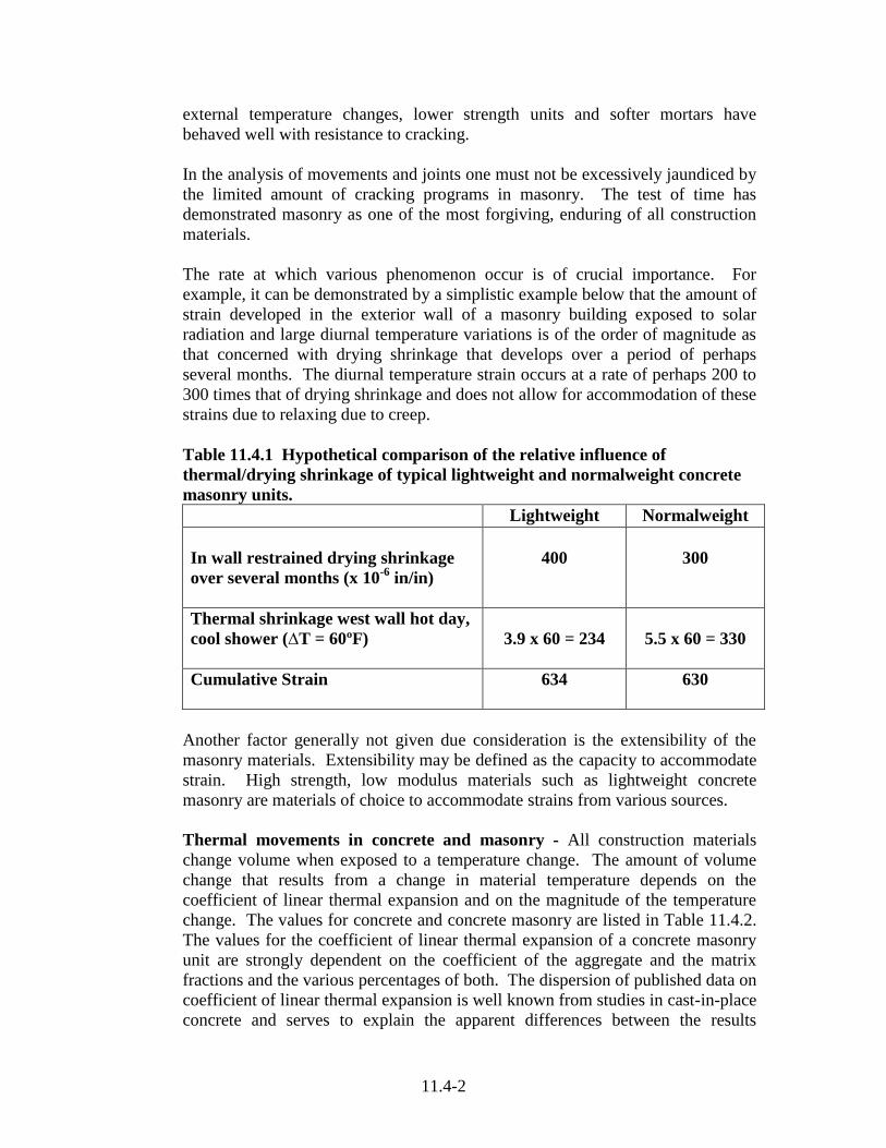
11.4-2
external temperature changes, lower strength units and softer mortars have
behaved well with resistance to cracking.
In the analysis of movements and joints one must not be excessively jaundiced by
the limited amount of cracking programs in masonry. The test of time has
demonstrated masonry as one of the most forgiving, enduring of all construction
materials.
The rate at which various phenomenon occur is of crucial importance. For
example, it can be demonstrated by a simplistic example below that the amount of
strain developed in the exterior wall of a masonry building exposed to solar
radiation and large diurnal temperature variations is of the order of magnitude as
that concerned with drying shrinkage that develops over a period of perhaps
several months. The diurnal temperature strain occurs at a rate of perhaps 200 to
300 times that of drying shrinkage and does not allow for accommodation of these
strains due to relaxing due to creep.
Table 11.4.1 Hypothetical comparison of the relative influence of
thermal/drying shrinkage of typical lightweight and normalweight concrete
masonry units.
Lightweight Normalweight
In wall restrained drying shrinkage
over several months (x 10-6
in/in)
400
300
Thermal shrinkage west wall hot day,
cool shower (∆T = 60ºF)
3.9 x 60 = 234
5.5 x 60 = 330
Cumulative Strain
634
630
Another factor generally not given due consideration is the extensibility of the
masonry materials. Extensibility may be defined as the capacity to accommodate
strain. High strength, low modulus materials such as lightweight concrete
masonry are materials of choice to accommodate strains from various sources.
Thermal movements in concrete and masonry - All construction materials
change volume when exposed to a temperature change. The amount of volume
change that results from a change in material temperature depends on the
coefficient of linear thermal expansion and on the magnitude of the temperature
change. The values for concrete and concrete masonry are listed in Table 11.4.2.
The values for the coefficient of linear thermal expansion of a concrete masonry
unit are strongly dependent on the coefficient of the aggregate and the matrix
fractions and the various percentages of both. The dispersion of published data on
coefficient of linear thermal expansion is well known from studies in cast-in-place
concrete and serves to explain the apparent differences between the results
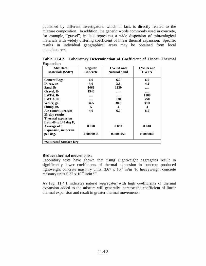
11.4-3
published by different investigators, which in fact, is directly related to the
mixture composition. In addition, the generic words commonly used in concrete,
for example, “gravel”, in fact represents a wide dispersion of mineralogical
materials with widely differing coefficient of linear thermal expansion. Specific
results in individual geographical areas may be obtained from local
manufacturers.
Table 11.4.2. Laboratory Determination of Coefficient of Linear Thermal
Expansion Mix Data
Materials (SSD*)
Regular
Concrete
LWCA and
Natural Sand
LWCA and
LWFA
Cement Bags
Darex, oz
Sand, lb
Gravel, lb
LWFA, lb
LWCA, lb
Water, gal
Slump, in.
Air content percent
35-day results:
Thermal expansion
from 40 to 140 deg F,
Average of 3
Expansion, in. per in.
per deg.
6.0
3.0
1068
1940
….
….
34.5
5
4.0
0.058
0.0000058
6.0
3.6
1320
….
….
930
38.0
4
6.0
0.050
0.0000050
6.0
4.2
….
….
1180
750
39.0
4
6.0
0.040
0.0000040
*Saturated Surface Dry
Reduce thermal movements: Laboratory tests have shown that using Lightweight aggregates result in
significantly lower coefficients of thermal expansion in concrete produced
lightweight concrete masonry units, 3.67 x 10⁻⁶
in/in ºF, heavyweight concrete
masonry units 5.32 x 10⁻⁶
in/in ºF.
As Fig. 11.4.1 indicates natural aggregates with high coefficients of thermal
expansion added to the mixture will generally increase the coefficient of linear
thermal expansion and result in greater thermal movements.

11.4-4
Figure 11.4.1 Thermal Expansion of Concrete Products.
Impact Resistance of Lightweight Concrete Masonry Walls
Numerous prison type security structures have been successfully constructed with
walls utilizing structural grade lightweight concrete masonry aggregate. Reported
below is a summary of the results of research into the impact resisting
performance of lightweight concrete masonry walls. The full report is included as
Appendix 11.4A.
To provide adequate security barrier walls, tests were conducted on several
grouted reinforced concrete walls where the strength of grout, strength and
density of the CMU were varied. All walls exceeded the security grade
requirements of ASTM F 2322, “Standard Test Methods for Physical Assault on
Vertical Fixed Barriers for Detention and Correctional Facilities”, shown in
Table 11.4.3.
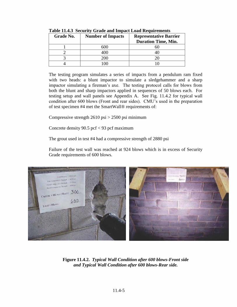
11.4-5
Table 11.4.3 Security Grade and Impact Load Requirements
Grade No. Number of Impacts Representative Barrier
Duration Time, Min.
1 600 60
2 400 40
3 200 20
4 100 10
The testing program simulates a series of impacts from a pendulum ram fixed
with two heads: a blunt impactor to simulate a sledgehammer and a sharp
impactor simulating a fireman’s axe. The testing protocol calls for blows from
both the blunt and sharp impactors applied in sequences of 50 blows each. For
testing setup and wall panels see Appendix A. See Fig. 11.4.2 for typical wall
condition after 600 blows (Front and rear sides). CMU’s used in the preparation
of test specimen #4 met the SmartWall® requirements of:
Compressive strength 2610 psi > 2500 psi minimum
Concrete density 90.5 pcf < 93 pcf maximum
The grout used in test #4 had a compressive strength of 2880 psi
Failure of the test wall was reached at 924 blows which is in excess of Security
Grade requirements of 600 blows.
Figure 11.4.2. Typical Wall Condition after 600 blows-Front side
and Typical Wall Condition after 600 blows-Rear side.

11.4-6
Air Barrier Resistance - Air barrier resistance requirements are increasing from
both a commercial acceptance and future governmental regulation perspectives.
The negative effects of air leakage include:
Increased energy costs
Metal stud corrosion
Tie and reinforcement corrosion
Increased possibility of efflorescence
Mold and mildew
Degradation of insulation
At the present time (August 2006) information on the performance of concrete
masonry is limited. Research commitments have been supported and testing is
currently underway.
Code Requirements - Air barrier system code requirements require air leakage
control compliance:
Material compliance – The air barrier material in an assembly must have
an air permeance not to exceed a flow of 0.004 cfm/sf at 1.57 psf (0.02 l/s
• m² @ 75 Pa) when tested in accordance with ASTM E 2178.
Assembly compliance – An air barrier assembly must have an air
permeance not to exceed 0.03 cfm/sf at 1.57 psf (0.15 l/s•m² at 75 Pa)
when tested according to ASTM E 1677.
These requirements have been developed because of reports that up to 40% of the
energy used by buildings for heating and cooling is lost due to infiltration.
Several governmental agencies have recently developed code requirements
mandating an air barrier system in the building envelope. A continuous air barrier
system is the combination of interconnected materials, flexible sealed joints and
the components of the building envelope that provide air-tightness.
Air Impermeability - Materials that have been identified as too air-permeable
include fiberboards and uncoated single wythe concrete block. Canada and
Massachusetts consider a flow of 0.004 cfm/sf as the maximum air leakage for a
material that can be used as part of the air barrier system. Flow of 0.004 happens
to be the air permeance of a sheet of 1/2" unpainted gypsum wall board.

11.4-7
According to one report the following materials do not qualify as an air barrier
material without additional coatings:
Uncoated concrete block
Plain and asphalt impregnated fiberboard
Expanded polystyrene
Batt and semi-fibrous insulator
Perforated house wraps
Asphalt impregnated felt (15 or 30 lb.)
Tongue and groove plank
Vermiculated insulation
Cellulose spray-on insulation
Walls that are constructed using materials that are very permeable to air, such as
concrete block, must be air-tightened using a coating either as a specially
formulated paint or air barrier sheet product, or a liquid spray-on or trowel-on
material (ANIS 2004).
Table11.4.4 Status of Testing in Accordance with ASTM E 2178 Sponsor Test
Facility
CMU Density Un-coated Coated Note
NECMA
10/03
Program
Bodycote 12 NW .046 .00102 Coated with
“ “ 8 NW .12 .00087 “ “
“ “ 8 LW ----- ----- (to be tested)
“ “ 8 NW .0005 Coated with (1)
NCMA
(no date)
NCMA HW ----- .02 One coat of paint
NCMA
(no date)
NCMA HW ----- .002 Two coats of
paint
ESCSI
12/04
NCMA LW 3820
92.6
----- .0609 1 coat of prep
rite primer and 1
coat of latex
interior
ESCSI
12/04
NCMA LW 3820
92.6
----- .003 1 coat of prep
rite primer and 2
coats of latex
interior
ESCSI 8/05 NCMA LW 3450
96
.33 Wait for cure
Test @ 28
NCMA
8/05
NCMA NW 0.6 to 1.0 Wait for cure
Test @ 28
(1) Coated with Sherman Williams Conflex XL Elastomeric Coating (50-60 ft²/gal) on top of
Luxor block surfacer (50-75 ft²/gal)


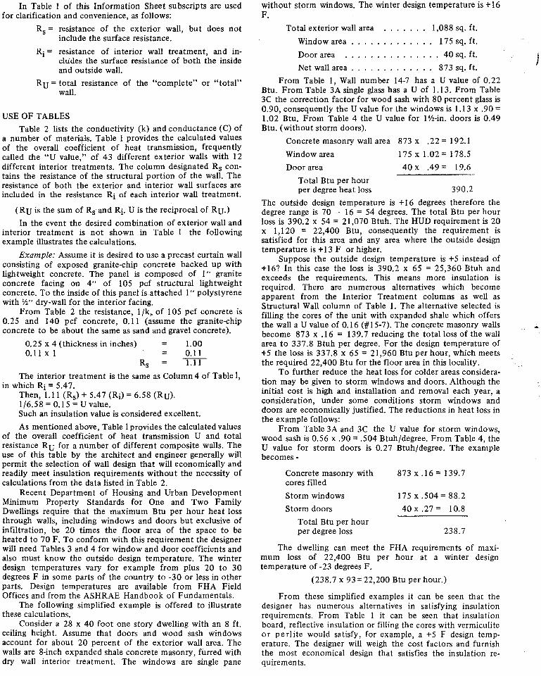
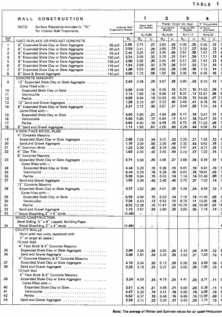


For Peer Review O
nly
2/3/2006 1
THERMAL INERTIA OF CONCRETE AND CONCRETE MASONRY 1T.A. Holm, M. G. Van Geem, J.P. Ries 2
34
Biography 5(75 Words Maximum for each author) 6
7Thomas A. Holm, P.E., FACI is the Director of Engineering of the Expanded Shale, Clay and 8
Slate Institute, Richmond Virginia. Past-chairman of ACI Committees 213 and 122 and has 9
published more than 40 papers on concrete, masonry, thermo-physical and geotechnical issues, and 10
is the co-author of the Corps of Engineers’ State-of-the-Art Report on High-Strength, High-11
Durability, Low-Density Concrete for Applications in Severe Environments. 12
13 Martha G. Van Geem, PE, LEED AP, Principal Engineer, Manager Building Science and 14
Sustainability, CTLGroup, Skokie, Illinois. A graduate of the University of Illinois–UC, with a 15
degree in civil engineering, and University of Chicago with an MBA. Has published more than 70 16
articles on the thermal properties of concrete, thermal mass, energy conservation, sustainability, 17
and moisture problems in buildings. She is active in ASHRAE standard committees and ACI. 18
19
John P. Ries, P.E., FACI, President of the Expanded Shale, Clay and Slate Institute of Lightweight 20
Aggregate Industry. A graduate of Montana State University with a BS degree in civil engineering, 21
and current chairman of ACI 122, past chair of ACI 213 (7 years) past chair (10 years) of ASTM 22
Committee C 9.21 Lightweight Aggregates and Concrete and is active on ACI 216, 301, 211B, 23
Sustainability, High Performance Concrete and a member of the Sustaining Member Committee. 24
25 26Keywords: Calibrated hot box; concrete; concrete masonry; density; diffusivity; specific heat; 27
thermal conductivity; thermal damping; thermal inertia; thermal lag. 28
29
30
Page 1 of 17 ACI Journal Manuscript Submission
123456789101112131415161718192021222324252627282930313233343536373839404142434445464748495051525354555657585960

For Peer Review O
nly
2/3/2006 2
1ABSTRACT 2
3The thermal performance of wall systems is determined by two parameters. The steady-state 4
thermal resistance is well established in building codes. Thermal inertia, the reluctance of the wall 5
to change temperature when exposed to a dynamic temperature regime is considerably more 6
complicated, less well understood and has been approximated in codes and standards by crude 7
assumptions. 8
9
This paper reports the influence of density, conductivity and specific heat on the dynamic testing of 10
wall and unit specimens and the impact of these criteria on thermal lag, reduction in amplitude and 11
energy transfer. Also included is a theoretical determination of the optimum concrete density to 12
maximize the thermal inertia of a single wythe, homogenous wall. 13
14 INTRODUCTION 15
16 The thermal performance of wall systems is described by two parameters: 17
• Thermal resistance: the walls resistance to a steady-state heat flow. This is well established 18
and commonly referred to in building codes and marketing literature as the “R” value of the 19
wall or as “R” values of individual wall components. The reciprocal of thermal resistance is 20
thermal conductance, and for a homogenous material, thermal conductivity. 21
• Thermal inertia: Relates to the reluctance of the wall to change temperature when exposed 22
to a variable temperature regime. Thermal inertia depends on thermal conductivity, specific 23
heat, thermal diffusivity, and density. 24
Until recently, standard practice considered only the thermal resistance parameter because of the 25
simplicity and relative accuracy of the calculation of a steady-state heat flow for “light frame” 26
construction. Steady-state heat flow can be used to predict the thermal performance of wood and 27
Page 2 of 17ACI Journal Manuscript Submission
123456789101112131415161718192021222324252627282930313233343536373839404142434445464748495051525354555657585960

For Peer Review O
nly
2/3/2006 3
steel frame construction fairly accurately, but significantly under estimates the thermal performance 1
of masonry and concrete walls. While the performance of substantial wall systems (masonry, 2
concrete, etc.) have been intuitively understood and widely recognized for many centuries, the 3
procedure for defining the beneficial behavior of thermal inertia remains complex to calculate and 4
codify. 5
6
This paper presents data on the thermal characteristics of concrete mixtures used in the production 7
of concrete and concrete masonry units (CMU). This data will allow an improved understanding of 8
the influence on density of the block concrete on the thermal inertia of a masonry wall. The effects 9
of a wall’s thermal inertia on overall energy requirements of a building are complex and difficult to 10
reduce to one factor. This is because of the significant influence of variables which include: 11
seasonal and building orientation, diurnal weather conditions (particularly the solar affects and the 12
daily fluctuation of outdoor temperature relative to a constant indoor setting), the location of 13
insulation and many other factors beyond the scope of this paper. 14
RESEARCH SIGNIFICANCE 15
The International Energy Conservation Code (IECC) provides simple approximations that reflect 16
the influence of the thermal/physical properties of concrete that are used in the determination of 17
energy loss through building walls. This paper provides an analytical method for determining 18
optimum properties of cast-in-place concrete as well as the concrete used in the manufacture of 19
masonry units. Also reported on are modifications to specimen preparation that allow the 20
determination of the thermal diffusivity for zero slump (high void) of fresh concrete obtained at the 21
manufacturing facility. Thermal values obtained from these testing procedures support the changes 22
made in recent modifications to the IECC (2004) in the approximations used to qualify walls for 23
benefits obtained from thermal inertia. 24
Page 3 of 17 ACI Journal Manuscript Submission
123456789101112131415161718192021222324252627282930313233343536373839404142434445464748495051525354555657585960
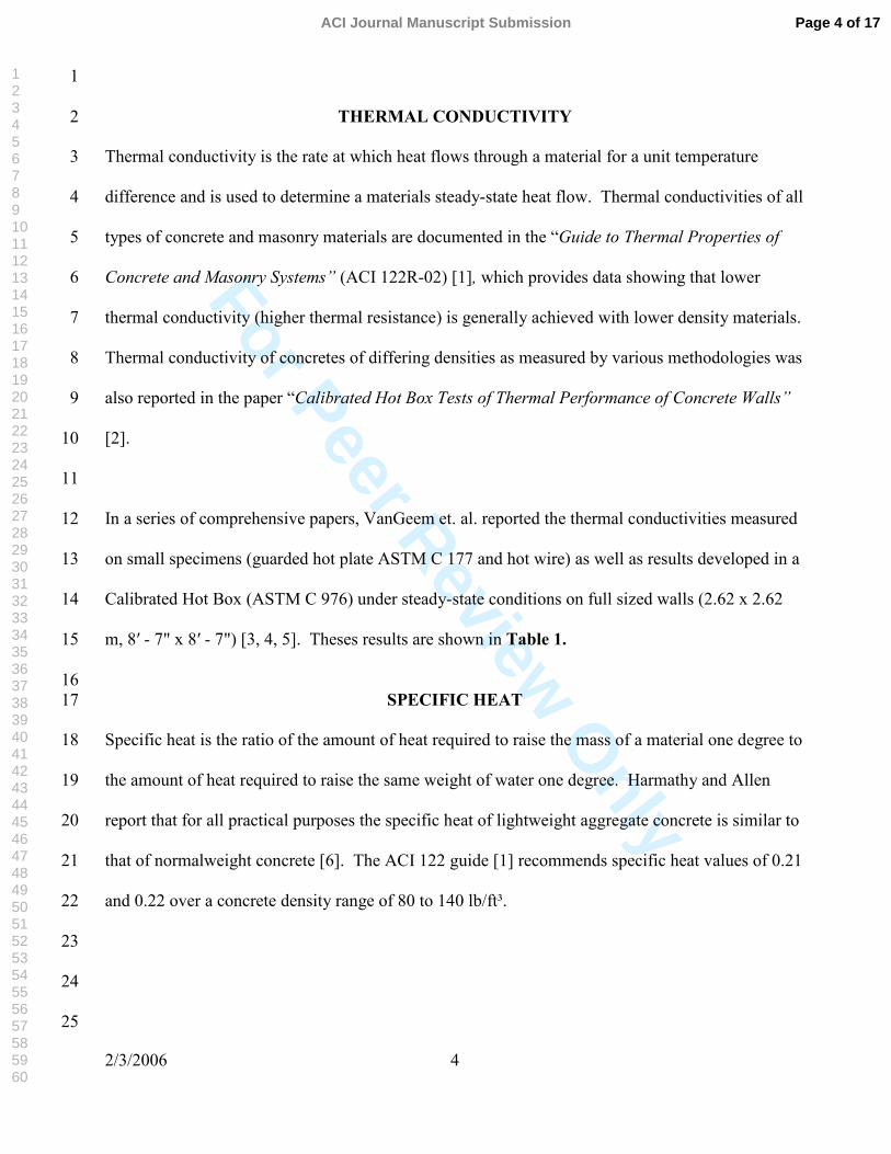
For Peer Review O
nly
2/3/2006 4
1
THERMAL CONDUCTIVITY 2
Thermal conductivity is the rate at which heat flows through a material for a unit temperature 3
difference and is used to determine a materials steady-state heat flow. Thermal conductivities of all 4
types of concrete and masonry materials are documented in the “Guide to Thermal Properties of 5
Concrete and Masonry Systems” (ACI 122R-02) [1], which provides data showing that lower 6
thermal conductivity (higher thermal resistance) is generally achieved with lower density materials. 7
Thermal conductivity of concretes of differing densities as measured by various methodologies was 8
also reported in the paper “Calibrated Hot Box Tests of Thermal Performance of Concrete Walls” 9
[2]. 10
11
In a series of comprehensive papers, VanGeem et. al. reported the thermal conductivities measured 12
on small specimens (guarded hot plate ASTM C 177 and hot wire) as well as results developed in a 13
Calibrated Hot Box (ASTM C 976) under steady-state conditions on full sized walls (2.62 x 2.62 14
m, 8′ - 7" x 8′ - 7") [3, 4, 5]. Theses results are shown in Table 1. 15
16 SPECIFIC HEAT 17
Specific heat is the ratio of the amount of heat required to raise the mass of a material one degree to 18
the amount of heat required to raise the same weight of water one degree. Harmathy and Allen 19
report that for all practical purposes the specific heat of lightweight aggregate concrete is similar to 20
that of normalweight concrete [6]. The ACI 122 guide [1] recommends specific heat values of 0.21 21
and 0.22 over a concrete density range of 80 to 140 lb/ft³. 22
23
24
25
Page 4 of 17ACI Journal Manuscript Submission
123456789101112131415161718192021222324252627282930313233343536373839404142434445464748495051525354555657585960
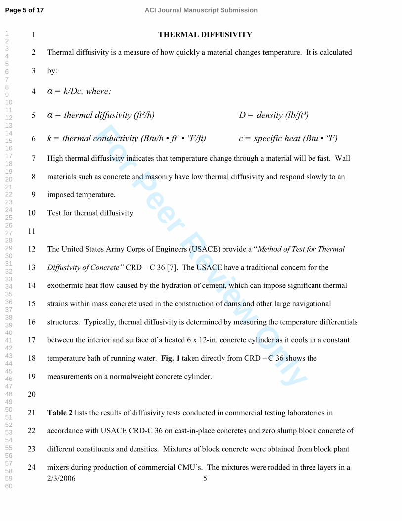
For Peer Review O
nly
2/3/2006 5
THERMAL DIFFUSIVITY 1
Thermal diffusivity is a measure of how quickly a material changes temperature. It is calculated 2
by: 3
α = k/Dc, where: 4
α = thermal diffusivity (ft²/h) D = density (lb/ft³) 5
k = thermal conductivity (Btu/h • ft² • ºF/ft) c = specific heat (Btu • ºF) 6
High thermal diffusivity indicates that temperature change through a material will be fast. Wall 7
materials such as concrete and masonry have low thermal diffusivity and respond slowly to an 8
imposed temperature. 9
Test for thermal diffusivity: 10
11
The United States Army Corps of Engineers (USACE) provide a “Method of Test for Thermal 12
Diffusivity of Concrete” CRD – C 36 [7]. The USACE have a traditional concern for the 13
exothermic heat flow caused by the hydration of cement, which can impose significant thermal 14
strains within mass concrete used in the construction of dams and other large navigational 15
structures. Typically, thermal diffusivity is determined by measuring the temperature differentials 16
between the interior and surface of a heated 6 x 12-in. concrete cylinder as it cools in a constant 17
temperature bath of running water. Fig. 1 taken directly from CRD – C 36 shows the 18
measurements on a normalweight concrete cylinder. 19
20
Table 2 lists the results of diffusivity tests conducted in commercial testing laboratories in 21
accordance with USACE CRD-C 36 on cast-in-place concretes and zero slump block concrete of 22
different constituents and densities. Mixtures of block concrete were obtained from block plant 23
mixers during production of commercial CMU’s. The mixtures were rodded in three layers in a 24
Page 5 of 17 ACI Journal Manuscript Submission
123456789101112131415161718192021222324252627282930313233343536373839404142434445464748495051525354555657585960

For Peer Review O
nly
2/3/2006 6
standard 6 x 12-in. cylinder mold with 25 blows/layer using a tamping rod in accordance with 1
ASTM C 192 “Standard Practice for Making and Curing Test Specimens in the Laboratory”. Care 2
was taken to locate the thermo-couple in the center of the cylinder. 3
4Using the formula proposed by Valore [8] as an approximation for the thermal conductivity of 5
moist concrete: 6
7k = 0.6e0.02D 8
9where k and D are as defined before, then the calculated conductivity of block concrete specimen 10S5 would yield kS5 = 0.6e0.02(90) = 3.6, resulting in a calculated diffusivity of: 11
12 13
14 15
16 It’s important to note that Valore’s formula is applicable only to lightweight concretes with 17
densities less than 100 lb/ft³. Thermal conductivity of concretes containing normalweight 18
aggregates with densities above 100 lb/ft³ can not be accurately estimated as a function of density 19
because of the wide range of mineralogy that directly effect the thermal conductivity of natural 20
aggregates giving them a large distribution range. 21
THERMAL LAG 22
Thermal lag is a measure of the response of the inside surface temperature to fluctuations in 23
outdoor temperature. Lag is sensitive to both thermal resistance and thermal inertia properties of 24
the wall. Using the calibrated hot box tests, references 3, 4 and 5 provide comprehensive data on 25
the results of steady-state and dynamic tests on full scale single layer cast concrete walls of 26
differing densities. These tests determined: 27
• Thermal lag: a measure of the response of inside and outside surface temperatures and heat 28
flow to fluctuations in outdoor temperature. 29
• Reduction in amplitude: The damping effect on peak heat flow. 30
0.016) results(test .x..s 016090210
12635 ==α
Page 6 of 17ACI Journal Manuscript Submission
123456789101112131415161718192021222324252627282930313233343536373839404142434445464748495051525354555657585960

For Peer Review O
nly
2/3/2006 7
• Reduction in measured energy: The energy necessary to maintain a constant indoor 1
temperature while outdoor temperature is varied compared to steady-state predictions. 2
3It can be seen from Table 3 that as the wall’s concrete density was reduced from 143 to 98 to 56 4
lb/ft³: 5
• Average thermal lag increased from 4 to 5.5 to 8.5 hours; 6
• Amplitude reduction increased from 45 to 54 to 63%; 7
• The ratio of total energy decreased from 66 to 60 to 53%. 8
It should be noted that these results are only comparative and were developed on the basis of the 9
wide temperature swing used in the NBS-10 test cycle (a simulated sol-air cycle used by the 10
National Bureau of Standards, now the National Institute of Standards and Technology) in which 11
mean outdoor temperature of the cycle was approximately equal to the mean indoor temperature. 12
For further details of the test instrumentation, analysis and commentary on application to total 13
energy demands, refer to reference 2. 14
Fig. 2 taken from Ref 11 depicts the thermal lag and reduction in amplitude (damping) on a 15
normalweight concrete wall in a moderate climate. 16
17
Thermal lag increases with an increase in 18
where:
20
L = wall thickness (ft) 21
P = length of dynamic cycle (hr) 22
= thermal diffusivity (ft²/hr) 23
Comparing walls of equal thickness L, subjected to the same dynamic cycle P, then thermal lag 24
PL α/2
α
Page 7 of 17 ACI Journal Manuscript Submission
123456789101112131415161718192021222324252627282930313233343536373839404142434445464748495051525354555657585960

For Peer Review O
nly
2/3/2006 8
is proportional to 1
2
3
and a direct comparison of the thermal lag of the three walls would be: 4
Wall C2 compared to wall C1 5
6
7
For the walls tested this ratio would be 8
9
10
11
12
In the dynamic tests conducted at CTLGroup the measured thermal lags for walls C2 and C3 were 13
1.4 and 2.1 times the thermal lag for wall C1, and therefore consistent with theoretical calculations. 14
In a similar fashion an estimate of the theoretical increase in thermal lag obtained by reducing the 15
density of the block concrete masonry walls from 114 lb/ft³ (Test No. S1) to 94 lb/ft³ (Test No. S2) 16
would be approximately 17
18
19
THERMAL MASS 20
The moderating effects on interior temperatures of internal walls are increased with higher 21
concrete densities for a given wall thickness, which result in high heat storage capacity. This is 22
commonly referred to as the effect of thermal mass. However, with regard to exterior single layer 23
un-insulated concrete product walls, the beneficial effects of thermal inertia, as characterized by the 24
α1
LW
NW
NWLW
11
αα
αα=÷
and C1wallofthat times1.5 bewouldC2oflag thermalor the 1.5 0155.037.
=
C1. wallofthat times2.1 bewouldC3oflag thermalor the 2.1 00849.037.
=
increase) (17% ... 17101600220
=
Page 8 of 17ACI Journal Manuscript Submission
123456789101112131415161718192021222324252627282930313233343536373839404142434445464748495051525354555657585960

For Peer Review O
nly
2/3/2006 9
reluctance to change temperature (as a result of lower diffusivity), are increased when density is 1
reduced. These lower density concretes have enough density to provide thermal mass effects while 2
having a lower thermal conductivity than normalweight concrete. These combine to provide a 3
lower thermal diffusivity. 4
OPTIMUM CONCRETE DENSITY FOR MAXIMUM THERMAL INERTIA 5
Change in diffusivity with respect to concrete density is not linear, because thermal conductivity 6
increases exponentially when compared to increases in density. The velocity of temperature 7
penetration is further increased when the crystalinity of the minerals of ordinary sand and gravel 8
aggregates increases. Therefore, the results of thermal inertia of concrete walls (thermal lag, 9
amplitude reduction, lowering total energy) are significantly lower when density is reduced 10
(structural lightweight, insulating lightweight and aerated lightweight concretes). Indeed, if the 11
Valore formula for thermal conductivity is inserted into the diffusivity equation, then the 12
relationship between thermal lag and concrete density would be: 13
14
15
16
differentiating thermal lag with respect to density 17
Setting, the results to zero, results in a density of 50 pcf that will provide maximum thermal lag. 18
[9]. See appendix. 19
20
INTERNATIONAL ENERGY CONSERVATION CODE (IECC) 21
The IECC (2004 Supplement) provides decreased R-value requirements for above-grade mass walls 22
compared to frame walls in commercial buildings. Article 802.2.1 in Chapter 8 “Building Design 23
for Commercial Buildings” states that “mass walls” shall include walls weighing at least (1) 35 24
De
Dck
Dc02.0
6.0
1==α
−= −α 2
12
1D01.D2
1dD
/1d
Page 9 of 17 ACI Journal Manuscript Submission
123456789101112131415161718192021222324252627282930313233343536373839404142434445464748495051525354555657585960
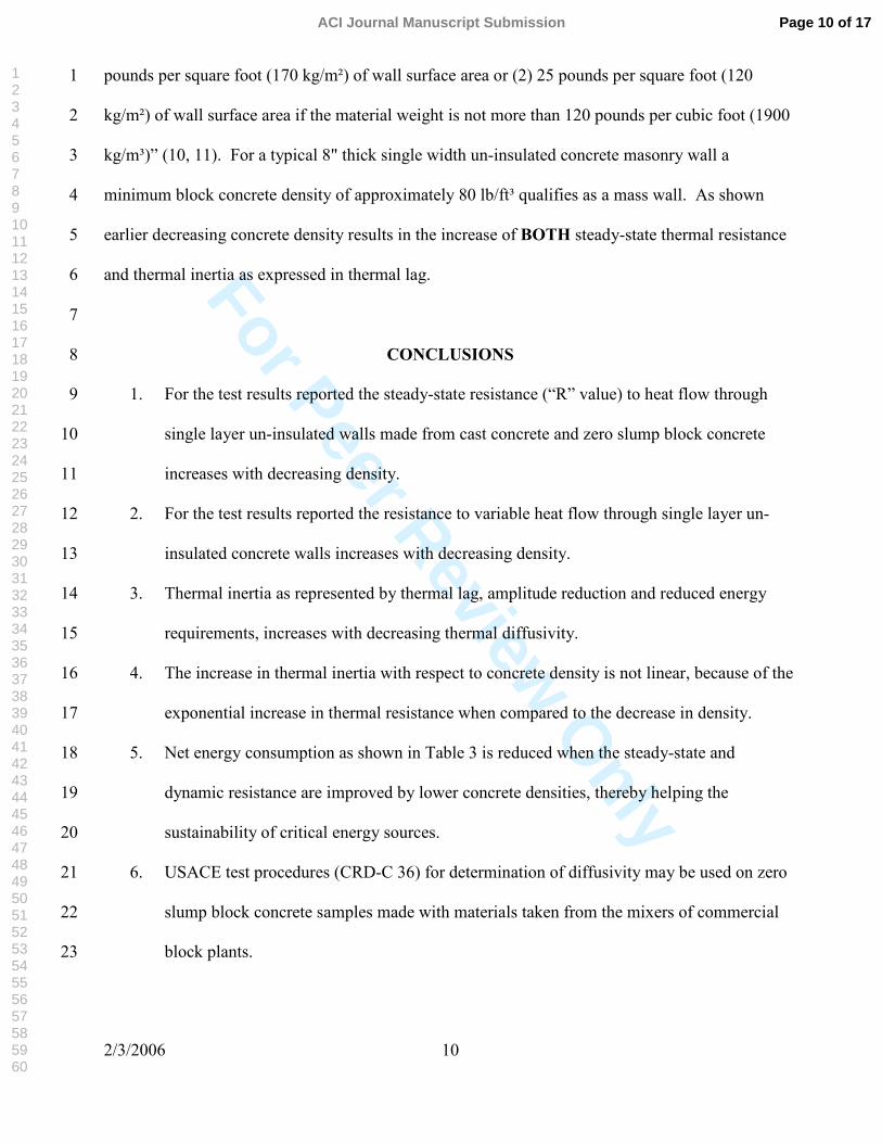
For Peer Review O
nly
2/3/2006 10
pounds per square foot (170 kg/m²) of wall surface area or (2) 25 pounds per square foot (120 1
kg/m²) of wall surface area if the material weight is not more than 120 pounds per cubic foot (1900 2
kg/m³)” (10, 11). For a typical 8" thick single width un-insulated concrete masonry wall a 3
minimum block concrete density of approximately 80 lb/ft³ qualifies as a mass wall. As shown 4
earlier decreasing concrete density results in the increase of BOTH steady-state thermal resistance 5
and thermal inertia as expressed in thermal lag. 6
7
CONCLUSIONS 8
1. For the test results reported the steady-state resistance (“R” value) to heat flow through 9
single layer un-insulated walls made from cast concrete and zero slump block concrete 10
increases with decreasing density. 11
2. For the test results reported the resistance to variable heat flow through single layer un-12
insulated concrete walls increases with decreasing density. 13
3. Thermal inertia as represented by thermal lag, amplitude reduction and reduced energy 14
requirements, increases with decreasing thermal diffusivity. 15
4. The increase in thermal inertia with respect to concrete density is not linear, because of the 16
exponential increase in thermal resistance when compared to the decrease in density. 17
5. Net energy consumption as shown in Table 3 is reduced when the steady-state and 18
dynamic resistance are improved by lower concrete densities, thereby helping the 19
sustainability of critical energy sources. 20
6. USACE test procedures (CRD-C 36) for determination of diffusivity may be used on zero 21
slump block concrete samples made with materials taken from the mixers of commercial 22
block plants. 23
Page 10 of 17ACI Journal Manuscript Submission
123456789101112131415161718192021222324252627282930313233343536373839404142434445464748495051525354555657585960

For Peer Review O
nly
2/3/2006 11
7. The requirement of IECC 2004 Supplement Article 802.2.1 requiring a lower wall weight 1
(25 vs. 35 lb/ft³) for mass walls constructed with concrete densities less than 120 lb/ft³ is a 2
simple and effective approximation of the influence of the reduction in diffusivity, and 3
hence increased time lag of lower density concrete and concrete masonry. 4
5
REFERENCES 6
1. ACI 122R-02 “Guide to Thermal Properties of Concrete and Masonry Systems”, 7
American Concrete Institute, Farmington Hills, MI ,2002, www.aci-int.org8
2. VanGeem M.G.; Fiorato A.E. and Musser D.W., “Calibrated Hot Box Tests of Thermal 9
Performance of Concrete Walls”, Proceedings of the ASHRAE/DOE Conference on 10
Thermal Performance of the Exterior Envelopes of Buildings II, Las Vegas, NV. 11
December 1982, ASHRAE SP-38, Atlanta 1983. 12
3. VanGeem M.G.; Fiorato A.E.; and Julien J.T., “Heat Transfer Characteristics of a 13
Normalweight Concrete Wall”, Oak Ridge National Laboratory Report No. 14
ORNL/Sub/79-42539/1, Construction Technology Laboratories (CTLGroup) Portland 15
Cement Association, Serial No. 0886, Skokie, IL 1983, 89 pages. www.CTLGroup.com16
4. VanGeem M.G. and Fiorato A.E., “Heat Transfer Characteristics of a Structural 17
Lightweight Concrete Wall”, Oak Ridge National Laboratory Report No. ORNL/Sub/79-18
42539/2, Construction Technology Laboratories (CTLGroup), Portland Cement 19
Association, Serial No. 0887, Skokie, IL 1983 pages. www.CTLGroup.com20
5. VanGeem M.G. and Fiorato A.E., “Heat Transfer Characteristics of a Low Density 21
Concrete Wall”, Oak Ridge National Laboratory Report No. ORNL/Sub/79-42539/3, 22
Construction Technology Laboratories (CTLGroup), Portland Cement Association Serial 23
No. 0885, Skokie, IL 1983, 89 pages. www.CTLGroup.com24
Page 11 of 17 ACI Journal Manuscript Submission
123456789101112131415161718192021222324252627282930313233343536373839404142434445464748495051525354555657585960

For Peer Review O
nly
2/3/2006 12
6. Harmathy T.E. and Allen L.W.; “Thermal Properties of Selected Masonry Unit 1
Concretes”, ACI Journal, February 1973, p. 123-142. 2
7. “Method of Test for Thermal Diffusivity of Concrete”, CRD-C 36 Handbook for Concrete 3
and Cement, U.S. Army Waterways Experimental Station, Vicksburg, MI, December 4
1973. 5
8. Valore, R.C. Jr.; “Calculation of U-Values of Hollow Concrete Masonry”, American 6
Concrete Institute, February 1980. 7
9. Bentz D.; Private communication October 2004 8
10. International Energy Conservation Code (IECC), International Code Council Inc., Country 9
Club Hills, IL, 2004. www.ICCsafe.org10
11. Eley, Charles “Thermal Mass Handbook Concrete and Masonry Design Provisions Using 11
ASHRAE IES 90.1-1989, National Codes and Standards Council of the Concrete & 12
Masonry Industries, 1994. 13
14
Page 12 of 17ACI Journal Manuscript Submission
123456789101112131415161718192021222324252627282930313233343536373839404142434445464748495051525354555657585960

For Peer Review O
nly
2/3/2006 13
APPENDIX 12
OPTIMUM CONCRETE DENSITY FOR MAXIMUM THERMAL INERTIA 3456789
Where: 10L = Wall thickness 11P = Sinusoidal temperature cycle 12α = Thermal diffusivity = k/DC where: 13k = Thermal conductivity 14D = Concrete Density 15c = Specific heat 16
17 Comparing the behavior of a single width homogenous wall with the same specific heat (c) and 18exposed to the same temperature cycle (P), then: 19
20 21
22 23
24 25
26 27
28 29
30 31
32 33
34 35
36 37
38 39
40 41
42 43
44 The solution is shown graphically in Figure A1. 45
46
kDc
PL
PL
:toalproprotion iswallhomogenous width single aofinertia hermal tThe
⋅=α=λ22
D.e.k
kD
02050recommends s"Assemblage Masonry and Concrete of
Properties Thermal the toGuide"122 ACI pcf 100-40ofdensity awithconcretes For
=
=λ
:then (D)density torespect withateddifferenti is)lag( thermal If02050α=λ D.e.
D
D.e.DD.eD 0150020
−=⋅=λ
D.e.D.D.e.DD
020500102502
1 −−−=∂
λ∂
−−=
∂
λ∂ 500105021020 .D..D/D.eD
( ) 5001050001050or001050or
0,
5050
020
===−=−
=∞→=∂λ∂
−
−
..D,D..D.D.
eDiespossibilit in two Results 0D
Setting
..
D.
Page 13 of 17 ACI Journal Manuscript Submission
123456789101112131415161718192021222324252627282930313233343536373839404142434445464748495051525354555657585960

For Peer Review O
nly
2/3/2006 14
TABLES AND FIGURES 12
List of Tables: 34
Table 1 - Thermal Conductivity for Concretes of Differing Densities as Measured From Small 5Sized Specimens and Full Sized Walls (Excerpted from Ref [2]). 6
7Table 2 - - Results of Diffusivity Tests measured on Structural Concretes and zero slump block 8
concrete of Different Densities 910
Table 3 - Excerpt from Table 5 “Summary of Dynamic Test Results for NBS-10 Test Cycle” (Ref 112) 12
13 List of Figures: 14
15 Fig.1 - Calculation of thermal diffusivity of a concrete cylinder 16
17 Fig. A1 - Optimum concrete density for maximum thermal lag (Graphical solution from equations 18in Appendix A) 19
20 Fig. 2 - Time Lag and Temperature Damping 21
22 23
24 25Table 1 – Thermal Conductivity for Concretes of Differing Densities as Measured From 26
Small Sized Specimens and Full Sized Walls (Excerpted from Ref [2]). 27
Concrete Wall C1
NormalweightC2
Structural Lightweight*
C3 Insulating Non-
Structural
Density Fresh 147 103 56 Density Air Dry 144 99 48 Density Oven Dry 140 94 46 Thermal Conductivity measured by (Btu•in /h • ft² • ºF)
Hot Plate (ASTM C 177) 16.1 4.49 1.44 Hot Wire Conductivity at moisture content shown
Hot Wire Conductivity Oven Dry 14.0 5.1 1.3 Calibrated Hot Box @ Temp 52+3ºF (steady-state) ASTM C 976
11.64
4.69
1.38
• Structural lightweight concrete use both coarse and fine rotary kiln produced 28expanded shale. 29
30
Page 14 of 17ACI Journal Manuscript Submission
123456789101112131415161718192021222324252627282930313233343536373839404142434445464748495051525354555657585960
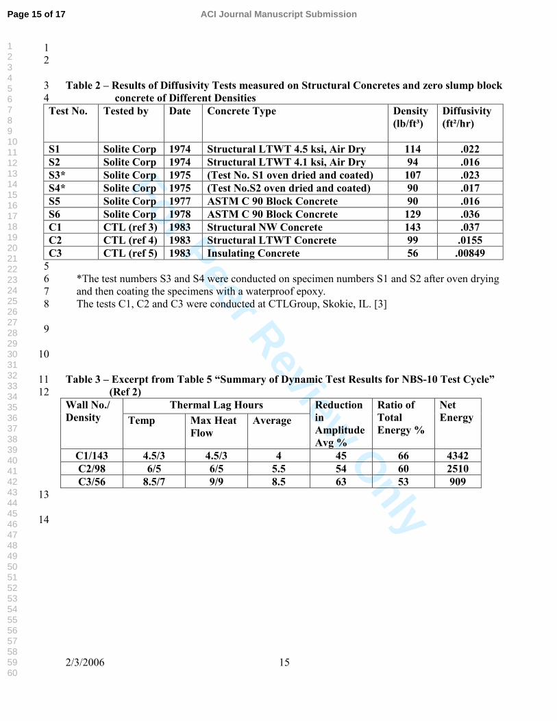
For Peer Review O
nly
2/3/2006 15
12
Table 2 – Results of Diffusivity Tests measured on Structural Concretes and zero slump block 3concrete of Different Densities 4
Test No. Tested by Date Concrete Type Density (lb/ft³)
Diffusivity (ft²/hr)
S1 Solite Corp 1974 Structural LTWT 4.5 ksi, Air Dry 114 .022 S2 Solite Corp 1974 Structural LTWT 4.1 ksi, Air Dry 94 .016 S3* Solite Corp 1975 (Test No. S1 oven dried and coated) 107 .023 S4* Solite Corp 1975 (Test No.S2 oven dried and coated) 90 .017 S5 Solite Corp 1977 ASTM C 90 Block Concrete 90 .016 S6 Solite Corp 1978 ASTM C 90 Block Concrete 129 .036 C1 CTL (ref 3) 1983 Structural NW Concrete 143 .037 C2 CTL (ref 4) 1983 Structural LTWT Concrete 99 .0155 C3 CTL (ref 5) 1983 Insulating Concrete 56 .00849
5*The test numbers S3 and S4 were conducted on specimen numbers S1 and S2 after oven drying 6and then coating the specimens with a waterproof epoxy. 7The tests C1, C2 and C3 were conducted at CTLGroup, Skokie, IL. [3] 8
9
10
Table 3 – Excerpt from Table 5 “Summary of Dynamic Test Results for NBS-10 Test Cycle” 11(Ref 2) 12
Thermal Lag Hours Wall No./ Density Temp Max Heat
Flow Average
Reduction in Amplitude Avg %
Ratio of Total Energy %
Net Energy
C1/143 4.5/3 4.5/3 4 45 66 4342 C2/98 6/5 6/5 5.5 54 60 2510 C3/56 8.5/7 9/9 8.5 63 53 909
13
14
Page 15 of 17 ACI Journal Manuscript Submission
123456789101112131415161718192021222324252627282930313233343536373839404142434445464748495051525354555657585960

For Peer Review O
nly
2/3/2006 16
1
2
3
4
5
6
7
8
9
10
11
Figure 1 – Calculation of thermal diffusivity of a concrete cylinder 12
13 14
15 16
17 18
19 20
21 22
23 24
25 26
27 28
29 30
31 32
Figure 2 Time Lag and Temperature Damping 3334
3536
Page 16 of 17ACI Journal Manuscript Submission
123456789101112131415161718192021222324252627282930313233343536373839404142434445464748495051525354555657585960
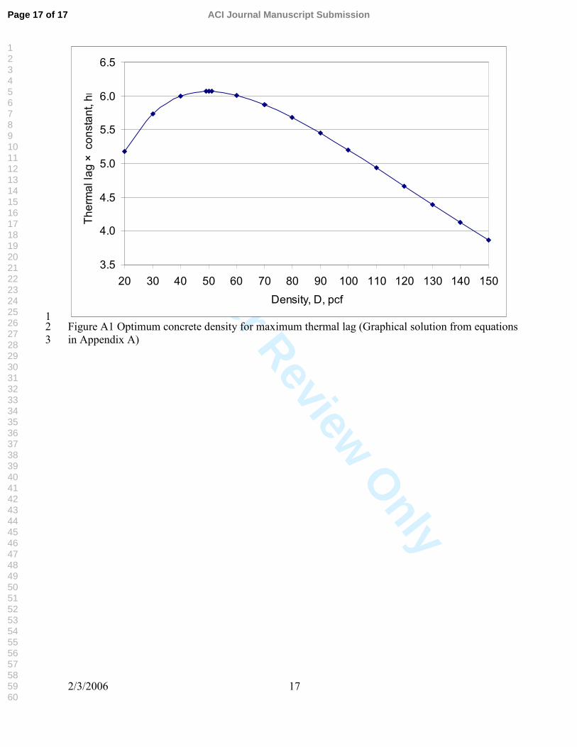
For Peer Review O
nly
2/3/2006 17
3.5
4.0
4.5
5.0
5.5
6.0
6.5
20 30 40 50 60 70 80 90 100 110 120 130 140 150Density, D, pcf
Ther
mal
lag
×co
nsta
nt,h
r
1Figure A1 Optimum concrete density for maximum thermal lag (Graphical solution from equations 2in Appendix A) 3
Page 17 of 17 ACI Journal Manuscript Submission
123456789101112131415161718192021222324252627282930313233343536373839404142434445464748495051525354555657585960

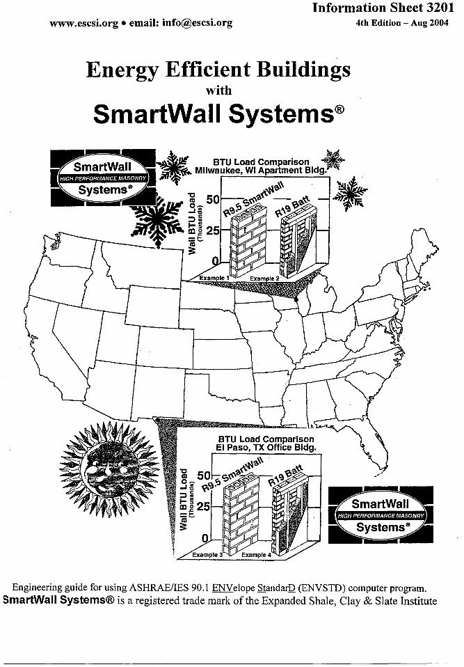


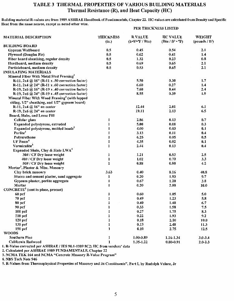

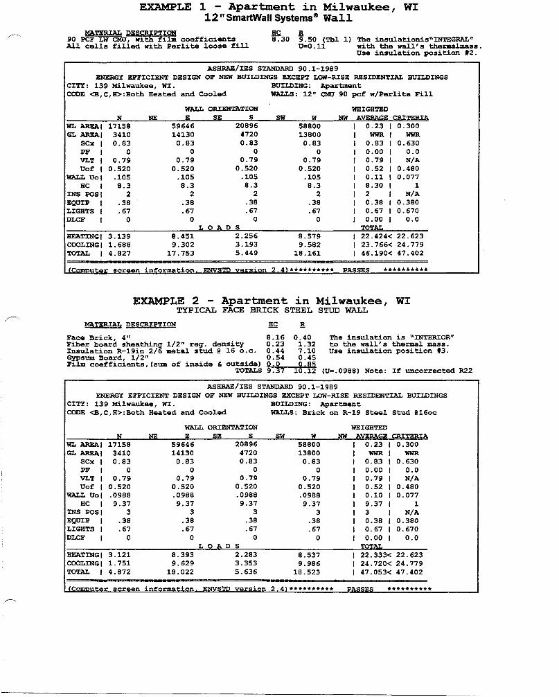
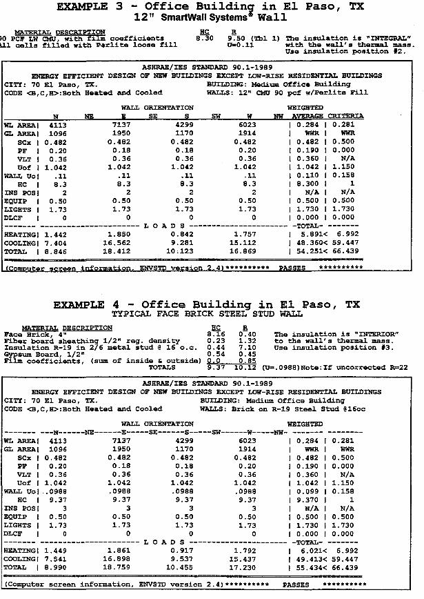


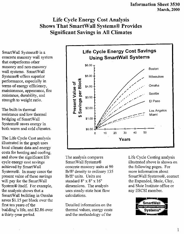


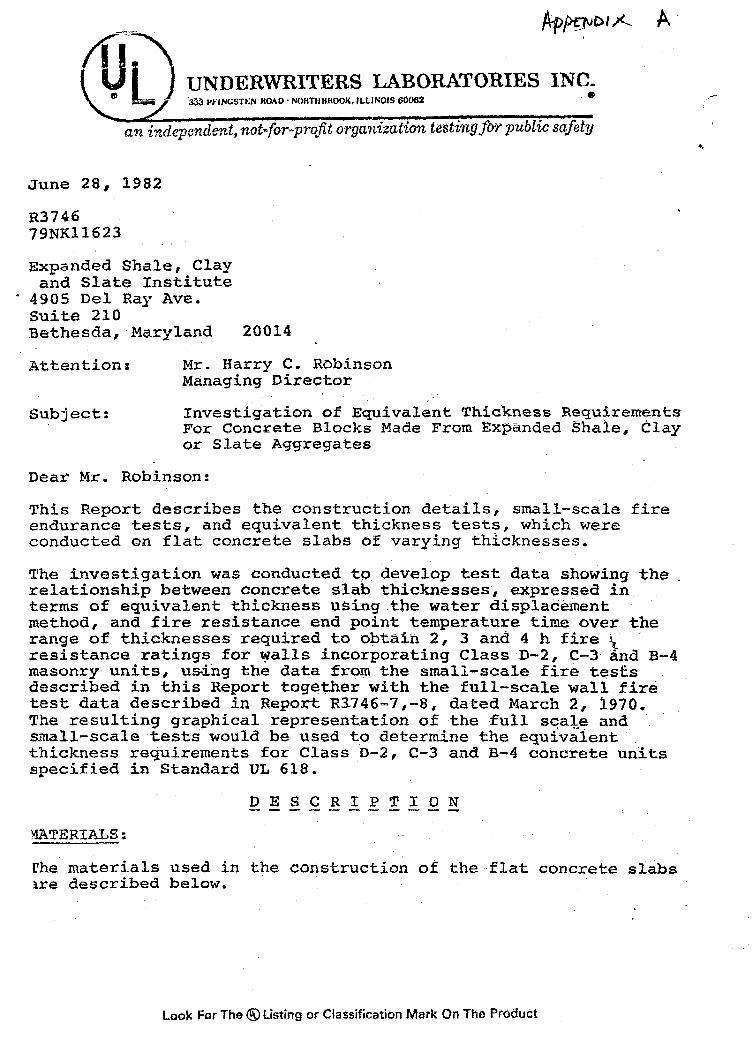


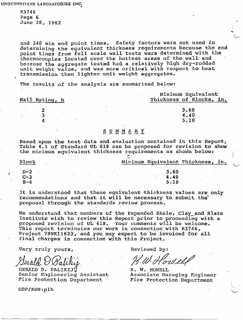
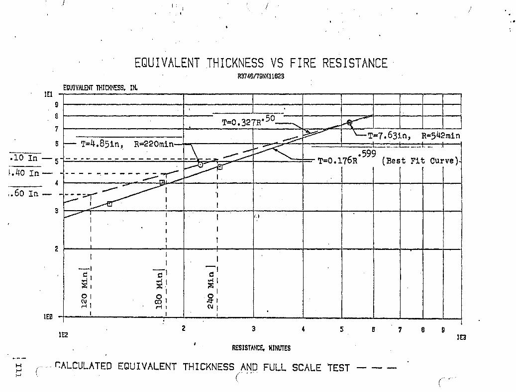


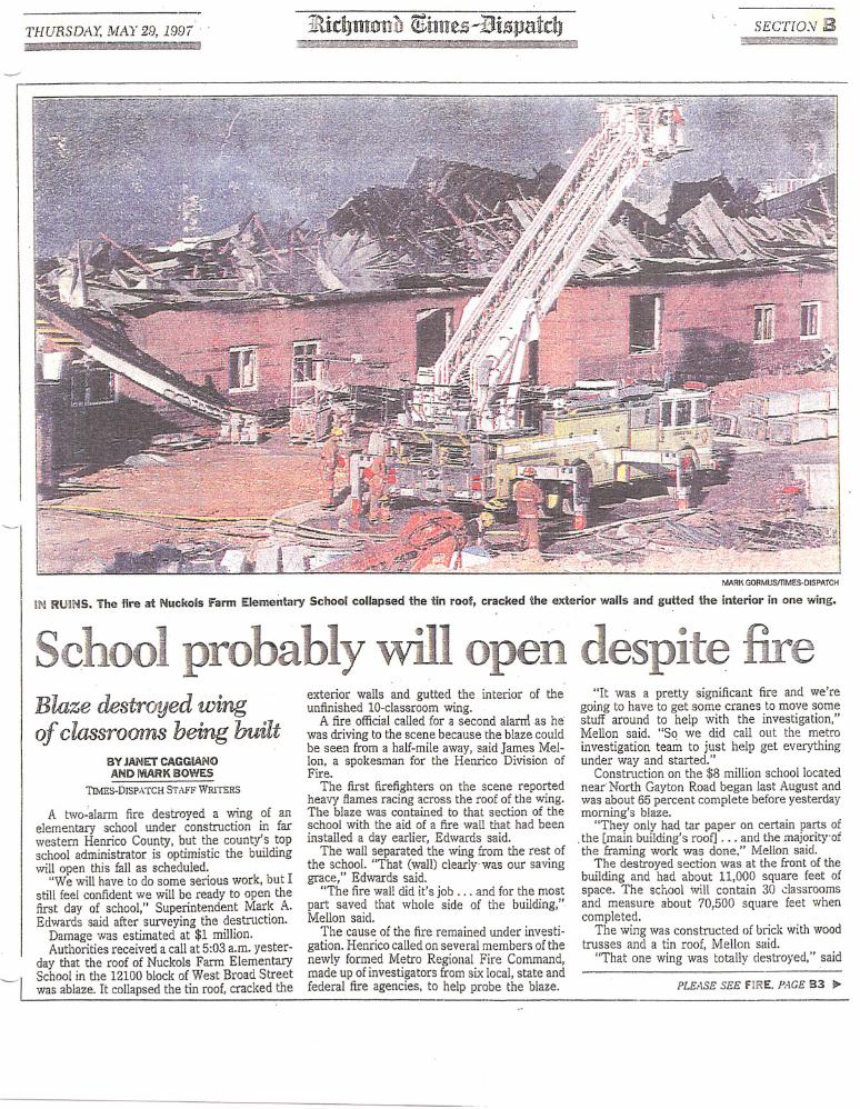


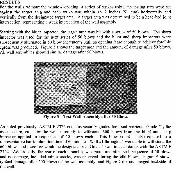


Related Documents