Chapter 11. Optical Interferometry Last Lecture • Two- Beam Interference • Young’s Double Slit Experiment • Virtual Sources • Newton’s Rings This Lecture • Michelson Interferometer • Variations of the Michelson Interferometer • Multiple - beam interference • Fabri - Perot interferometer

Welcome message from author
This document is posted to help you gain knowledge. Please leave a comment to let me know what you think about it! Share it to your friends and learn new things together.
Transcript
Chapter 11. Optical InterferometryChapter 11. Optical Interferometry
Last Lecture• Two- Beam Interference• Young’s Double Slit Experiment• Virtual Sources• Newton’s Rings
This Lecture• Michelson Interferometer• Variations of the Michelson Interferometer• Multiple- beam interference• Fabri- Perot interferometer
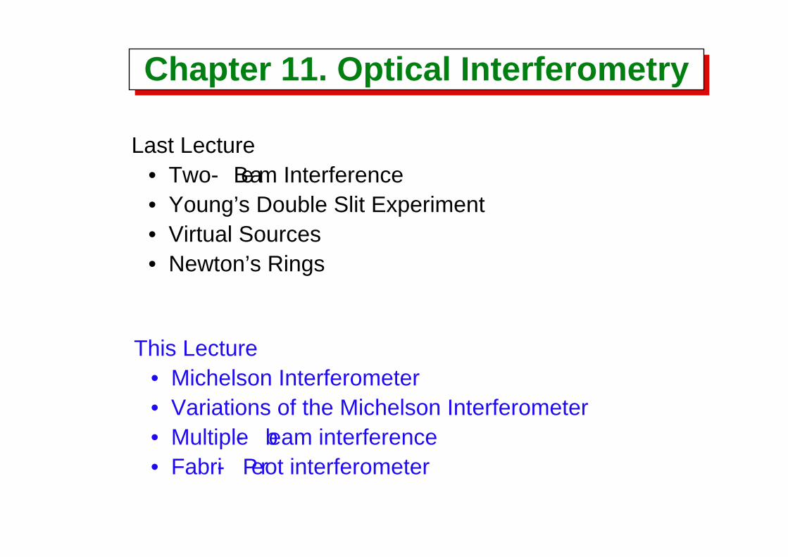
The Michelson InterferometerThe Michelson Interferometer
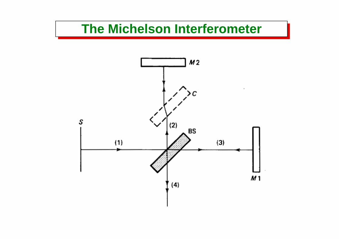
The Michelson InterferometerThe Michelson Interferometer
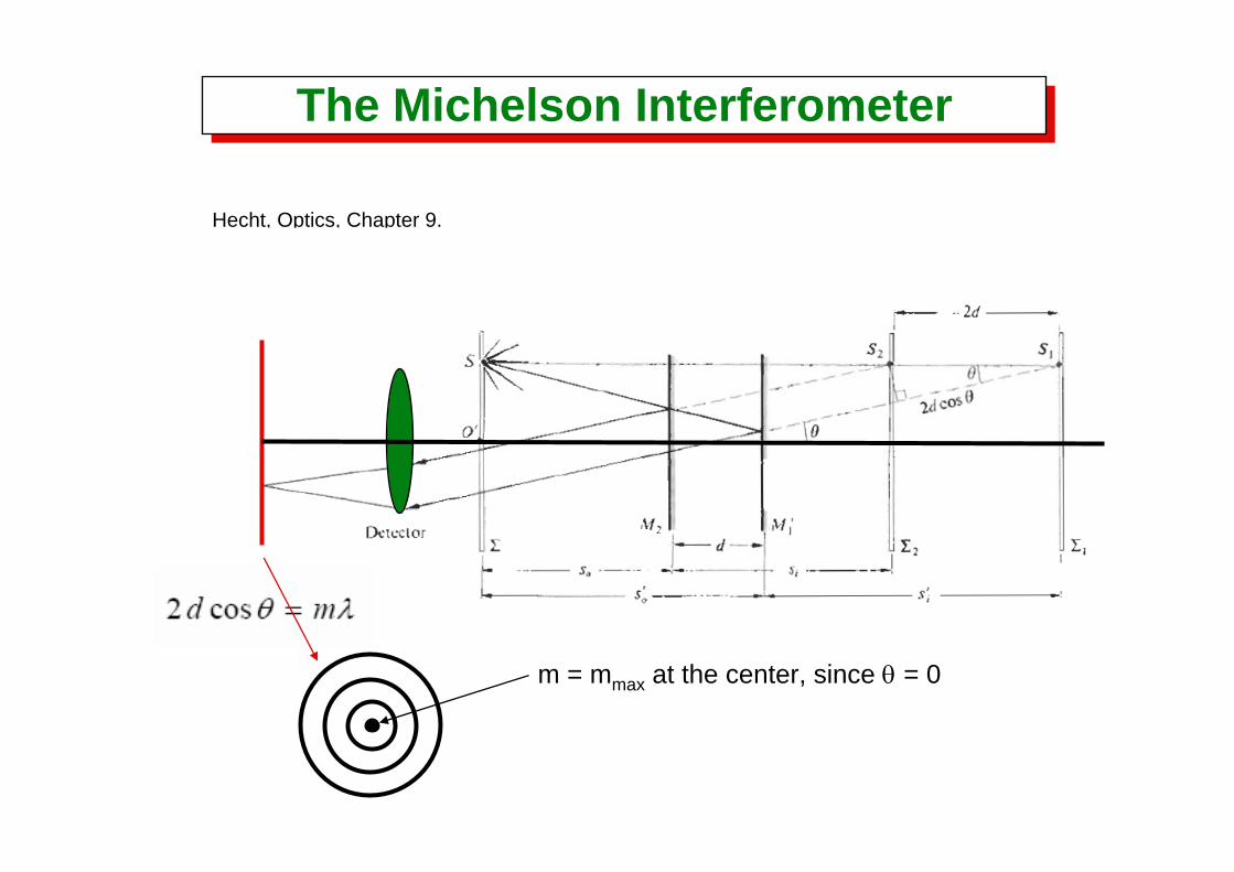
Hecht, Optics, Chapter 9.
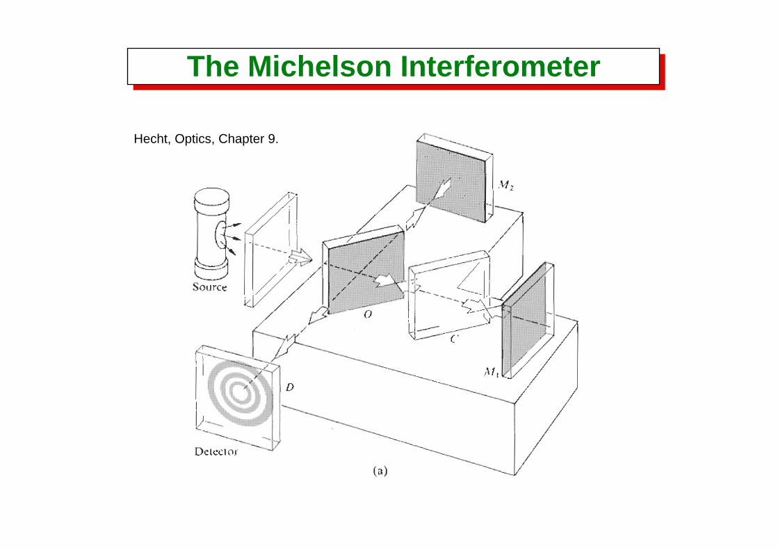
The Michelson InterferometerThe Michelson Interferometer
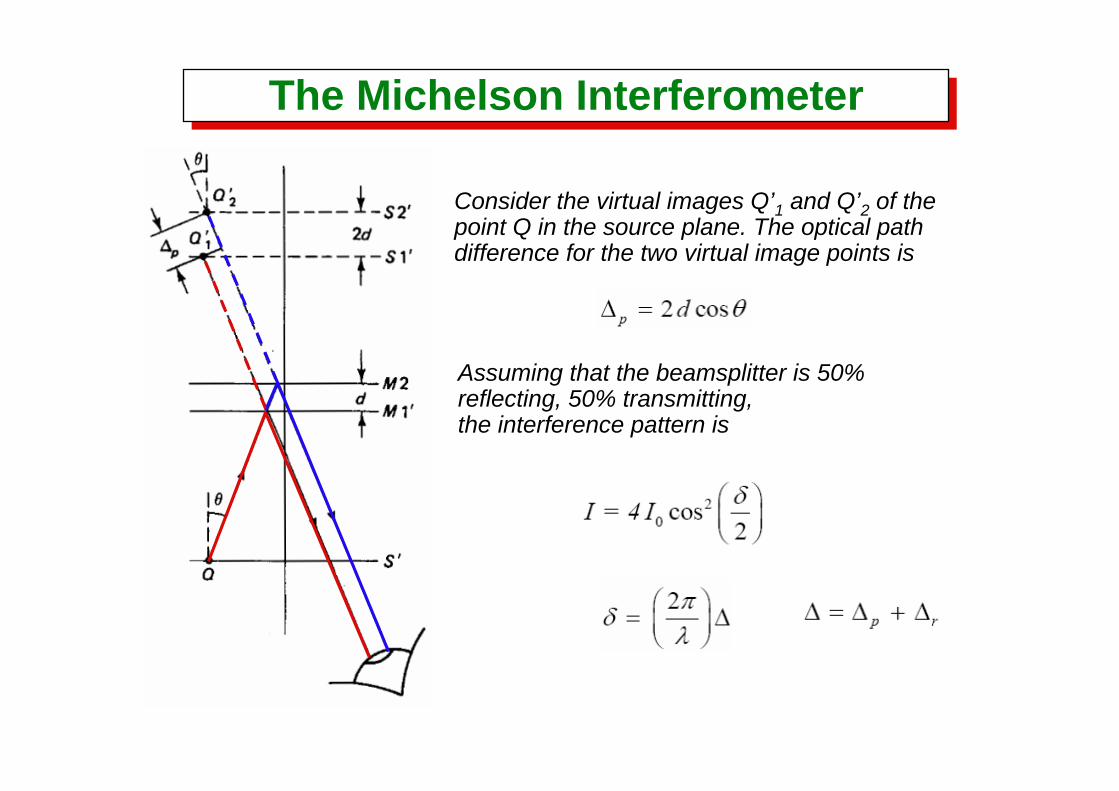
Consider the virtual images Q’1 and Q’2 of thepoint Q in the source plane. The optical pathdifference for the two virtual image points is
Assuming that the beamsplitter is 50% reflecting, 50% transmitting, the interference pattern is
The Michelson InterferometerThe Michelson Interferometer
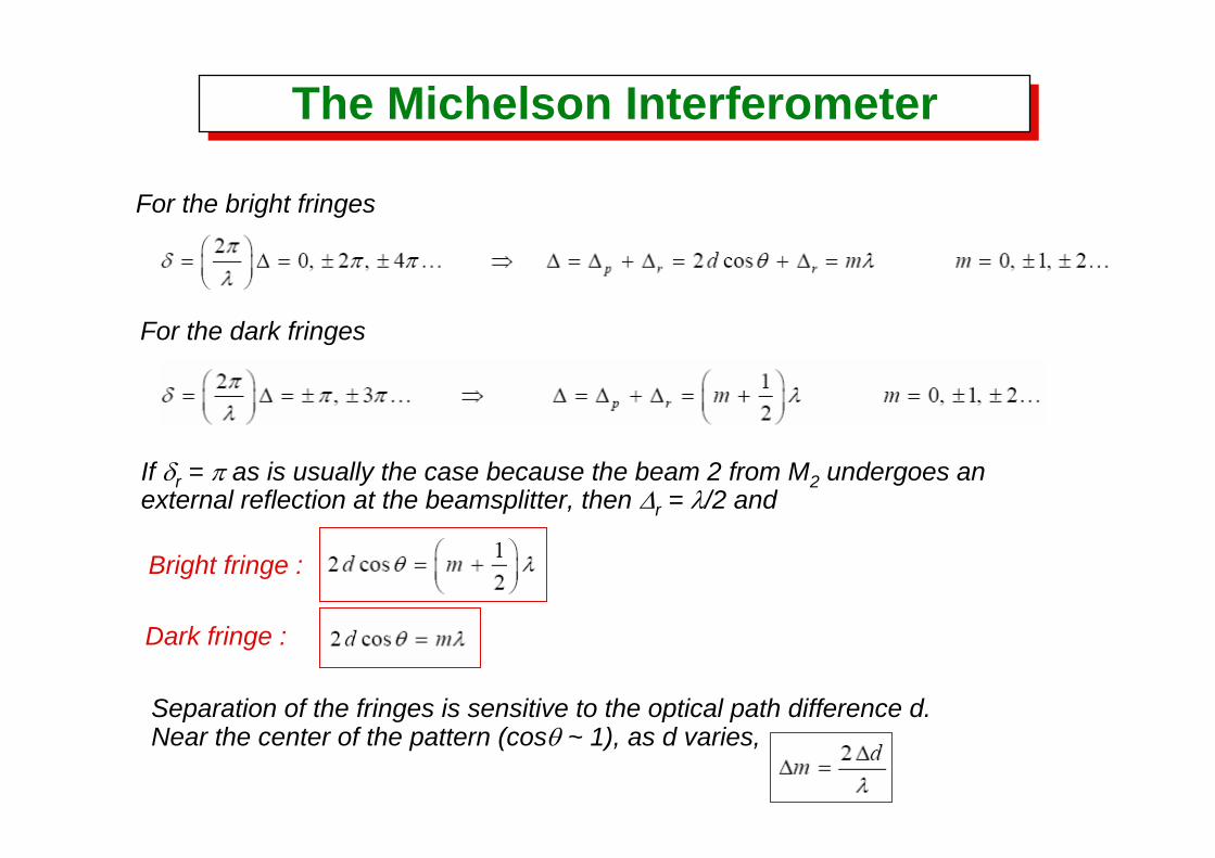
For the bright fringes
For the dark fringes
If δr = π as is usually the case because the beam 2 from M2 undergoes an external reflection at the beamsplitter, then Δr = λ/2 and
Bright fringe :
Dark fringe :
Separation of the fringes is sensitive to the optical path difference d.Near the center of the pattern (cosθ ~ 1), as d varies,
The Michelson InterferometerThe Michelson Interferometer
Hecht, Optics, Chapter 9.
m = mmax at the center, since θ = 0
The Michelson InterferometerThe Michelson Interferometer
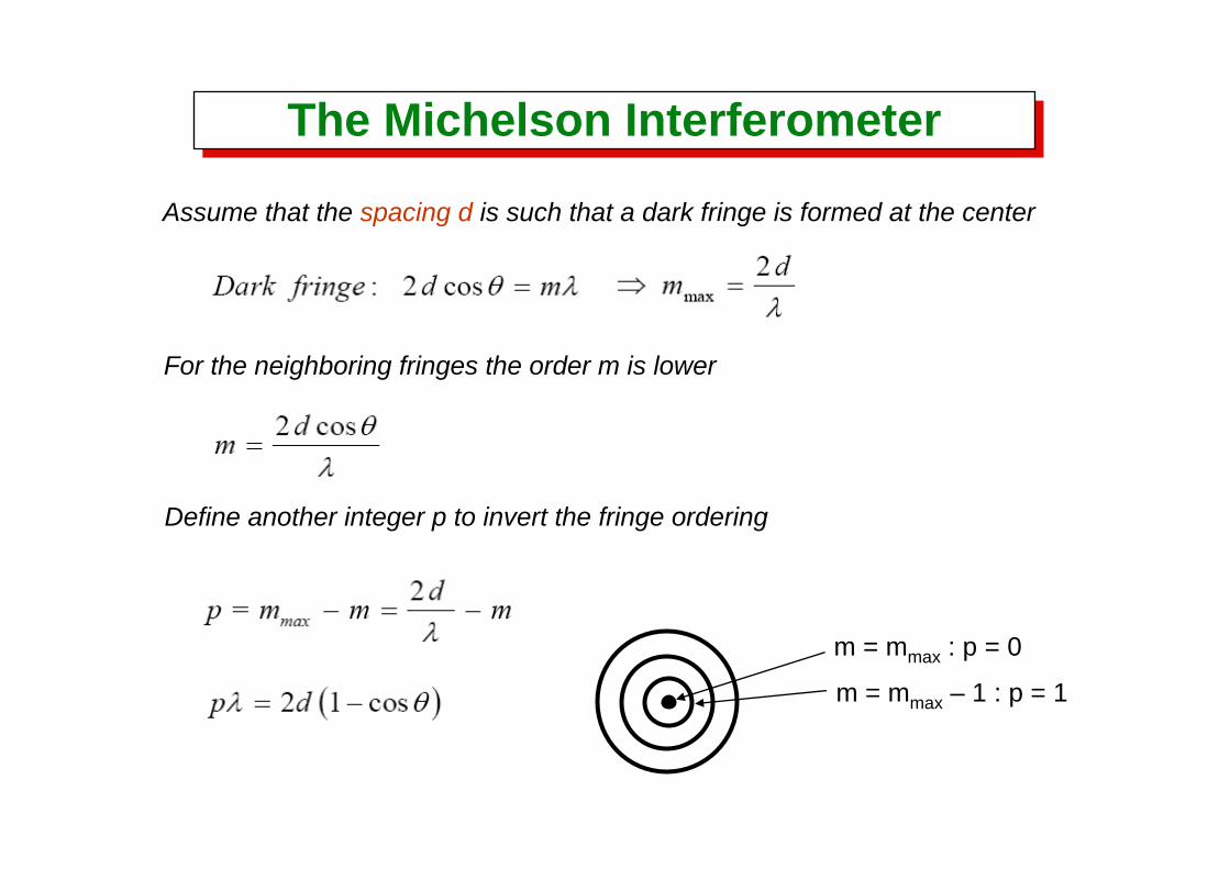
Assume that the spacing d is such that a dark fringe is formed at the center
For the neighboring fringes the order m is lower
Define another integer p to invert the fringe ordering
m = mmax : p = 0
m = mmax – 1 : p = 1
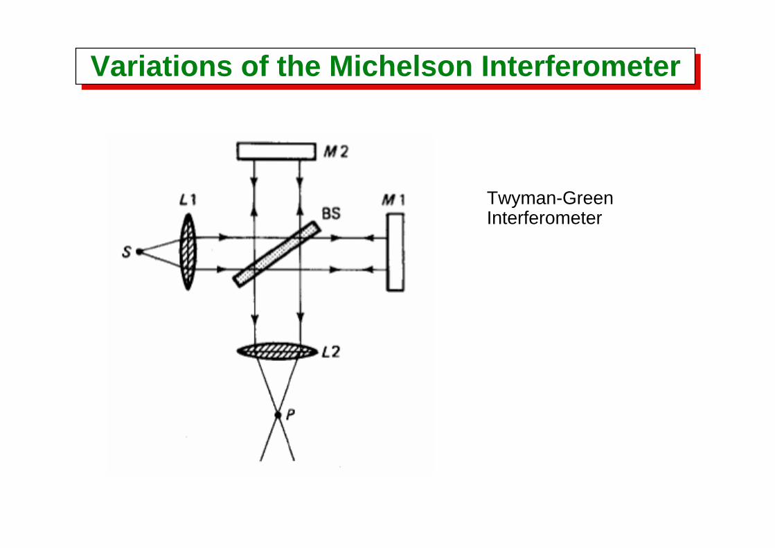
Variations of the Michelson InterferometerVariations of the Michelson Interferometer
Twyman-Green Interferometer
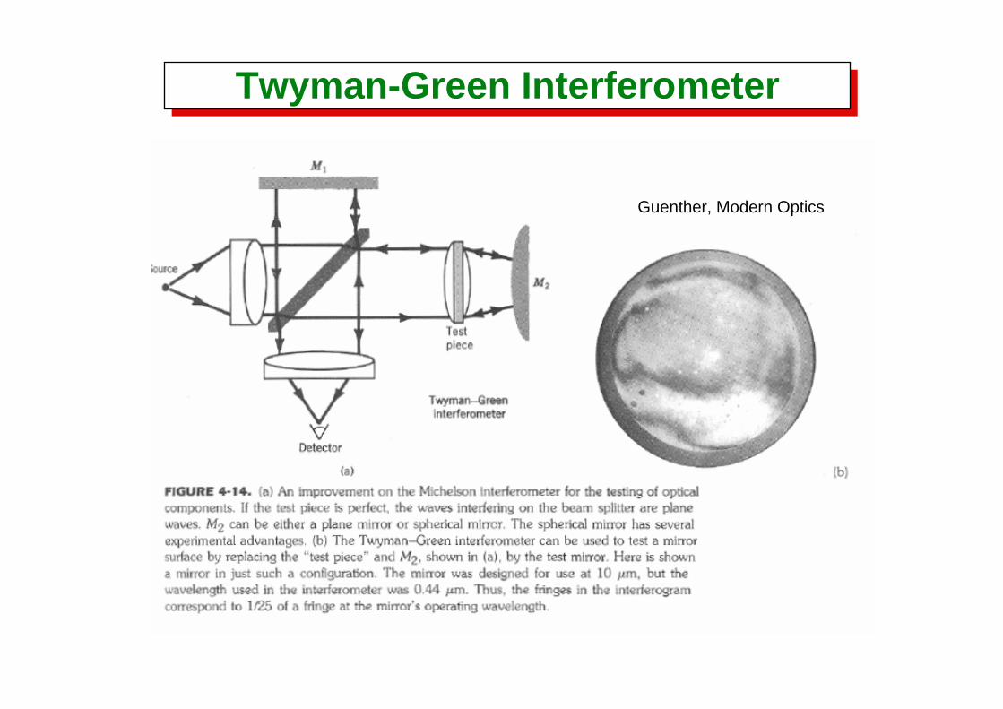
Twyman-Green InterferometerTwyman-Green Interferometer
Guenther, Modern Optics
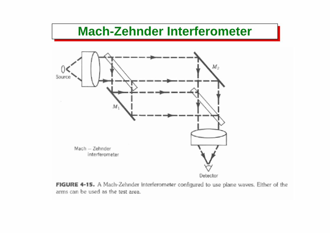
Mach-Zehnder InterferometerMach-Zehnder Interferometer
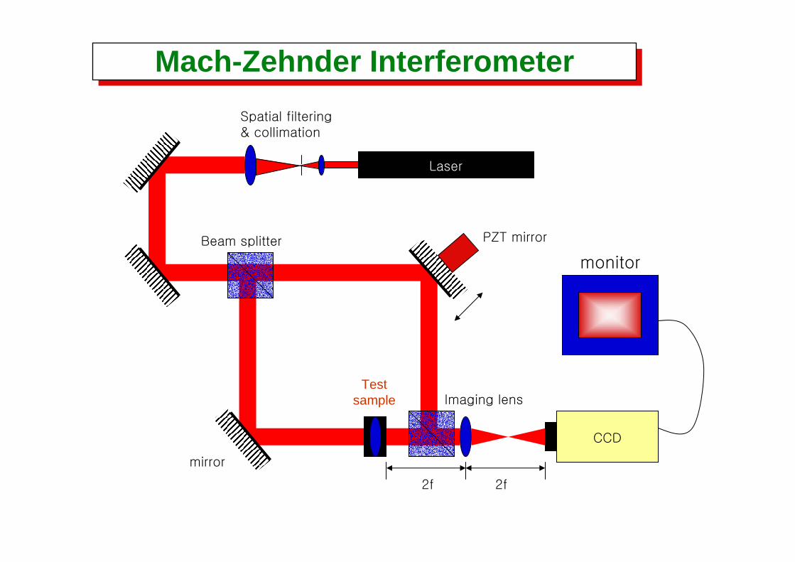
Laser
CCD
mirror
PZT mirror
Spatial filtering& collimation
Beam splitter
2f 2f
Imaging lens
monitor
Testsample
Mach-Zehnder InterferometerMach-Zehnder Interferometer
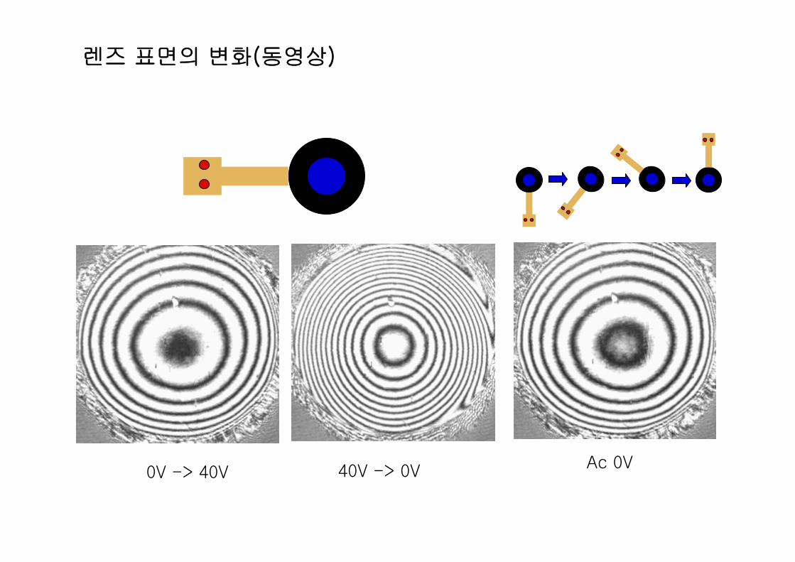
렌즈 표면의 변화(동영상)
Ac 0V0V -> 40V 40V -> 0V
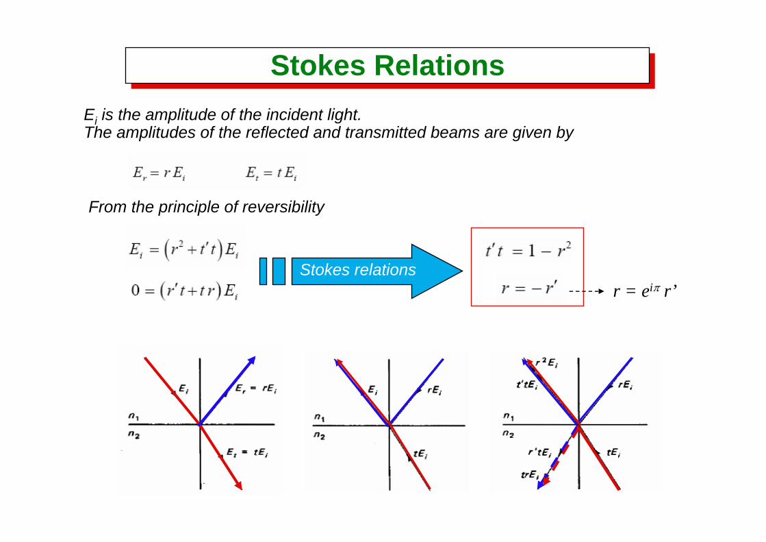
Stokes RelationsStokes RelationsEi is the amplitude of the incident light.The amplitudes of the reflected and transmitted beams are given by
From the principle of reversibility
Stokes relationsr = eiπ r’
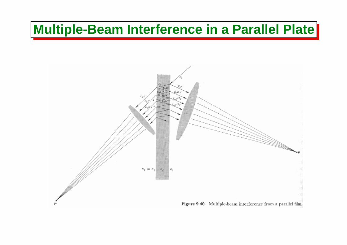
Multiple-Beam Interference in a Parallel PlateMultiple-Beam Interference in a Parallel Plate
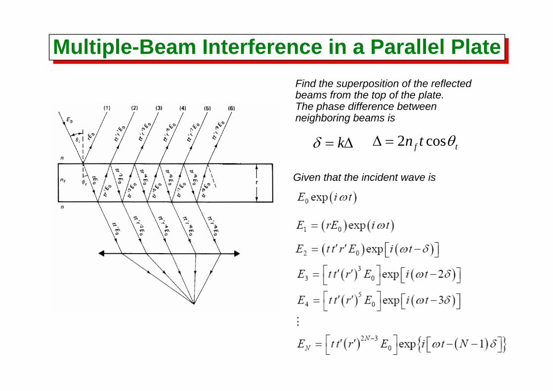
Find the superposition of the reflectedbeams from the top of the plate.The phase difference between neighboring beams is
Given that the incident wave is
Δ= kδ tf tn θcos2=Δ
Multiple-Beam Interference in a Parallel PlateMultiple-Beam Interference in a Parallel Plate
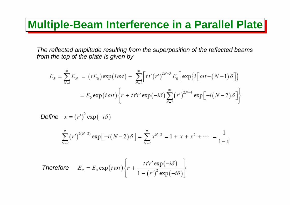
The reflected amplitude resulting from the superposition of the reflected beams from the top of the plate is given by
Define
Therefore
Multiple-Beam Interference in a Parallel PlateMultiple-Beam Interference in a Parallel Plate
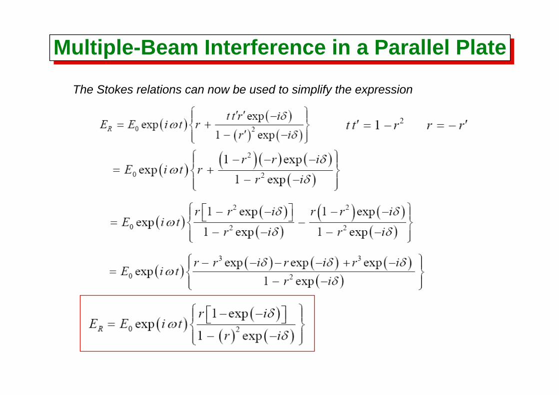
The Stokes relations can now be used to simplify the expression
Multiple-Beam Interference in a Parallel PlateMultiple-Beam Interference in a Parallel Plate
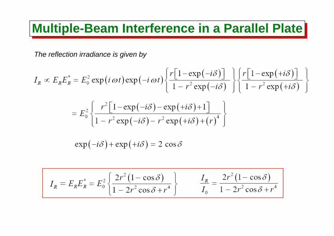
The reflection irradiance is given by
Multiple-Beam Interference in a Parallel PlateMultiple-Beam Interference in a Parallel Plate
Multiple-Beam Interference in a Parallel PlateMultiple-Beam Interference in a Parallel Plate
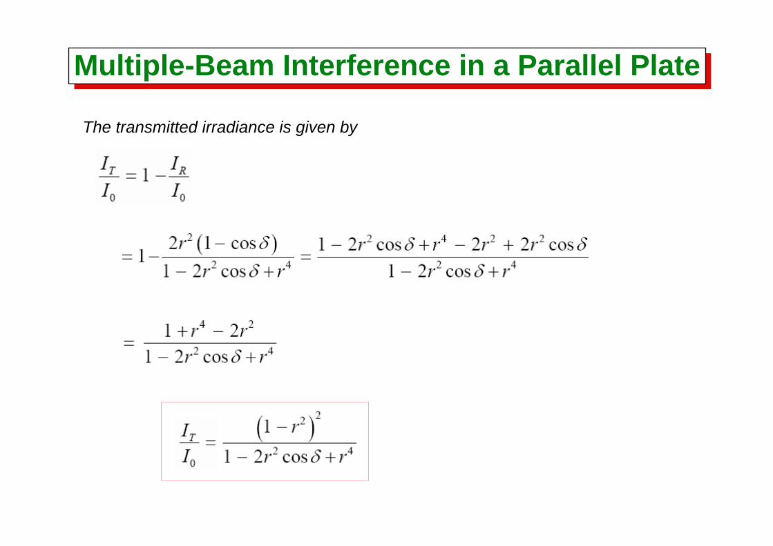
The transmitted irradiance is given by

Multiple-Beam Interference in a Parallel PlateMultiple-Beam Interference in a Parallel Plate
Minima in transmitted irradiance and maxima in reflected irradiance occur when
Minima in reflected irradiance and maxima in transmitted irradiance occur when

The Fabry-Perot Interferometer:High-Resolution Air-Spaced
The Fabry-Perot Interferometer:High-Resolution Air-Spaced
Inner surfaces polished to flatness of λ/50 or better, coated with silver or aluminum films with thickness of about 50 nm. The metal films are partially transmitting. The outer surfaces of the plates are wedged to eliminate spurious fringe patterns.
The Fabry-Perot InterferometerThe Fabry-Perot Interferometer
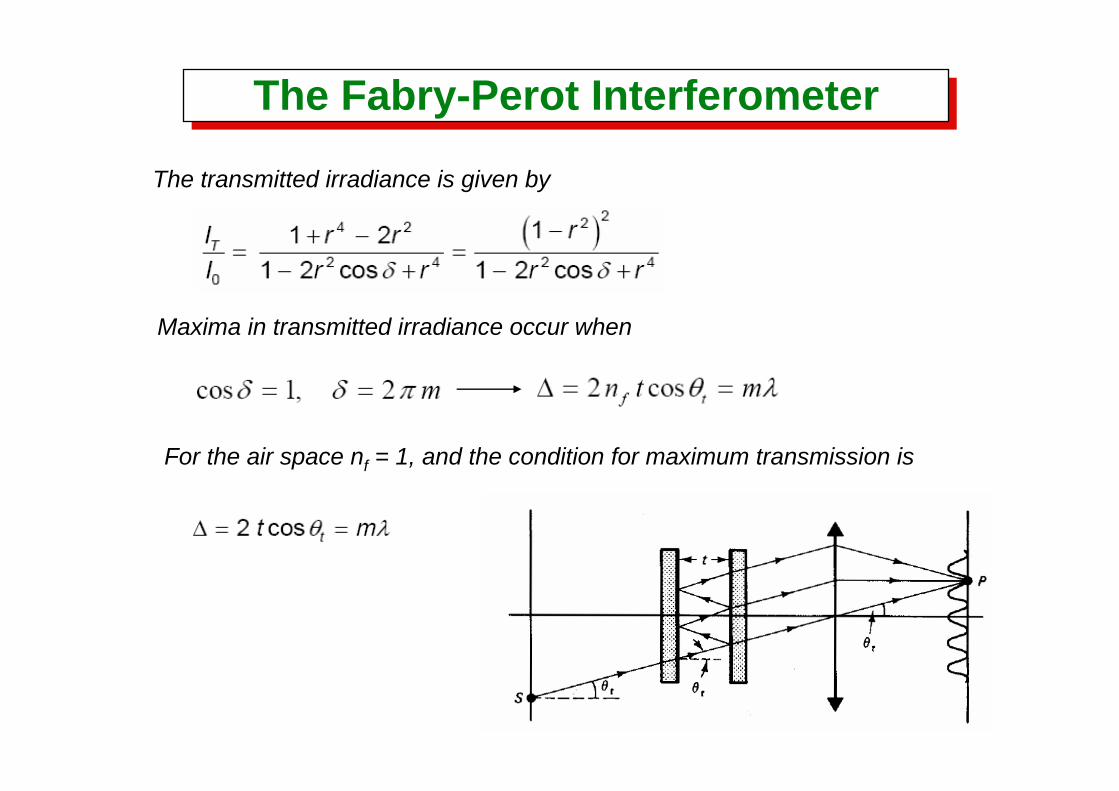
The transmitted irradiance is given by
Maxima in transmitted irradiance occur when
For the air space nf = 1, and the condition for maximum transmission is

The Fabry-Perot Interferometer:High-Resolution Air-Spaced
The Fabry-Perot Interferometer:High-Resolution Air-Spaced
The fringe pattern will shift as the wavelength of the light is scanned or as the thickness of the air gap is varied.
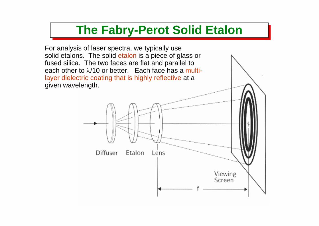
The Fabry-Perot Solid EtalonThe Fabry-Perot Solid EtalonFor analysis of laser spectra, we typically usesolid etalons. The solid etalon is a piece of glass or fused silica. The two faces are flat and parallel to each other to λ/10 or better. Each face has a multi-layer dielectric coating that is highly reflective at a given wavelength.
The Fabry-Perot Interferometer:Fringe profiles – The Airy functionThe Fabry-Perot Interferometer:
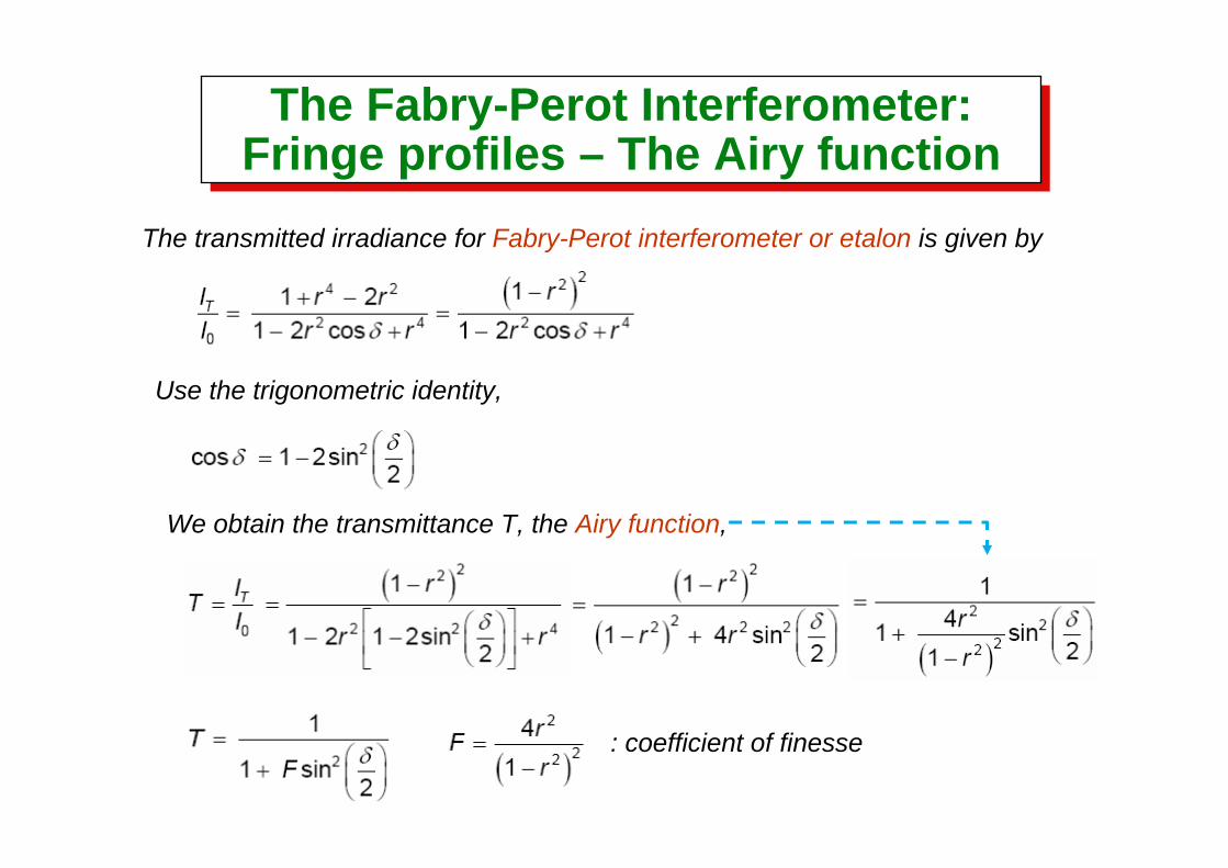
Fringe profiles – The Airy functionThe transmitted irradiance for Fabry-Perot interferometer or etalon is given by
Use the trigonometric identity,
We obtain the transmittance T, the Airy function,
: coefficient of finesse
The Fabry-Perot Interferometer:Fringe profiles – The Airy functionThe Fabry-Perot Interferometer:
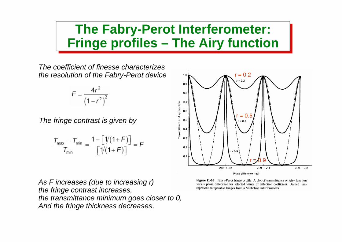
Fringe profiles – The Airy functionThe coefficient of finesse characterizesthe resolution of the Fabry-Perot device
The fringe contrast is given by
As F increases (due to increasing r)the fringe contrast increases, the transmittance minimum goes closer to 0, And the fringe thickness decreases.
r = 0.2
r = 0.5
r = 0.9
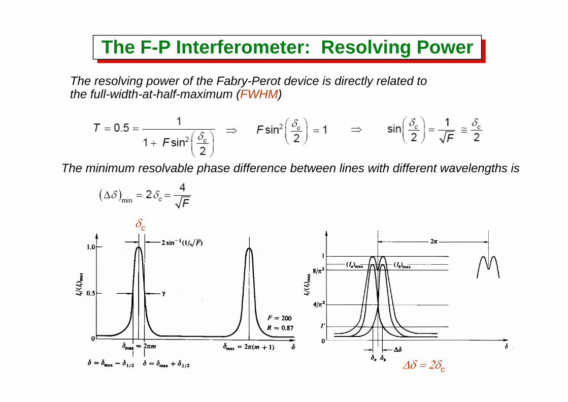
The F-P Interferometer: Resolving PowerThe F-P Interferometer: Resolving PowerThe resolving power of the Fabry-Perot device is directly related to the full-width-at-half-maximum (FWHM)
The minimum resolvable phase difference between lines with different wavelengths is
δc
Δδ = 2δc
Resolving PowerResolving Power
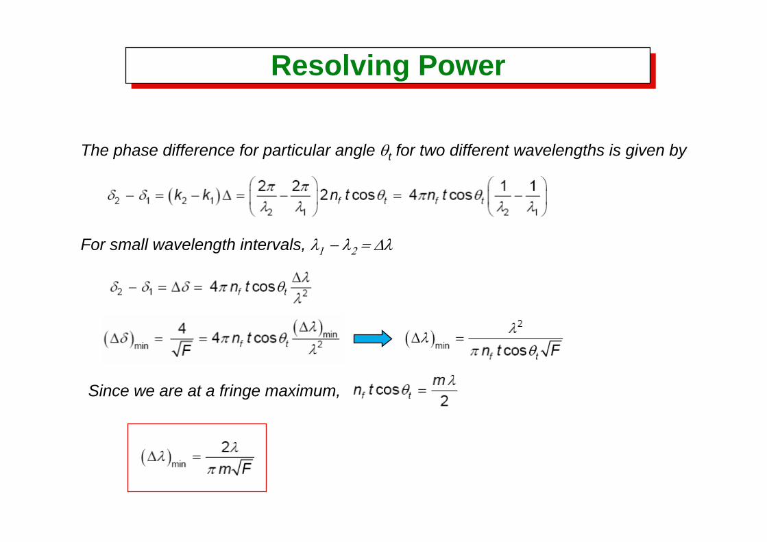
The phase difference for particular angle θt for two different wavelengths is given by
For small wavelength intervals, λ1 − λ2 = Δλ
Since we are at a fringe maximum,
Resolving PowerResolving Power
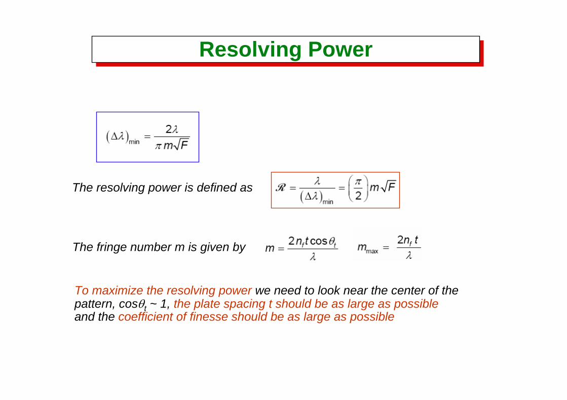
The resolving power is defined as
The fringe number m is given by
To maximize the resolving power we need to look near the center of the pattern, cosθt ~ 1, the plate spacing t should be as large as possibleand the coefficient of finesse should be as large as possible
Free Spectral RangeFree Spectral Range
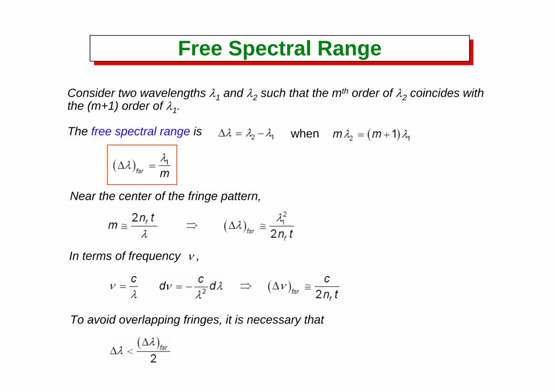
Consider two wavelengths λ1 and λ2 such that the mth order of λ2 coincides withthe (m+1) order of λ1.
The free spectral range is when
Near the center of the fringe pattern,
In terms of frequency ν ,
To avoid overlapping fringes, it is necessary that
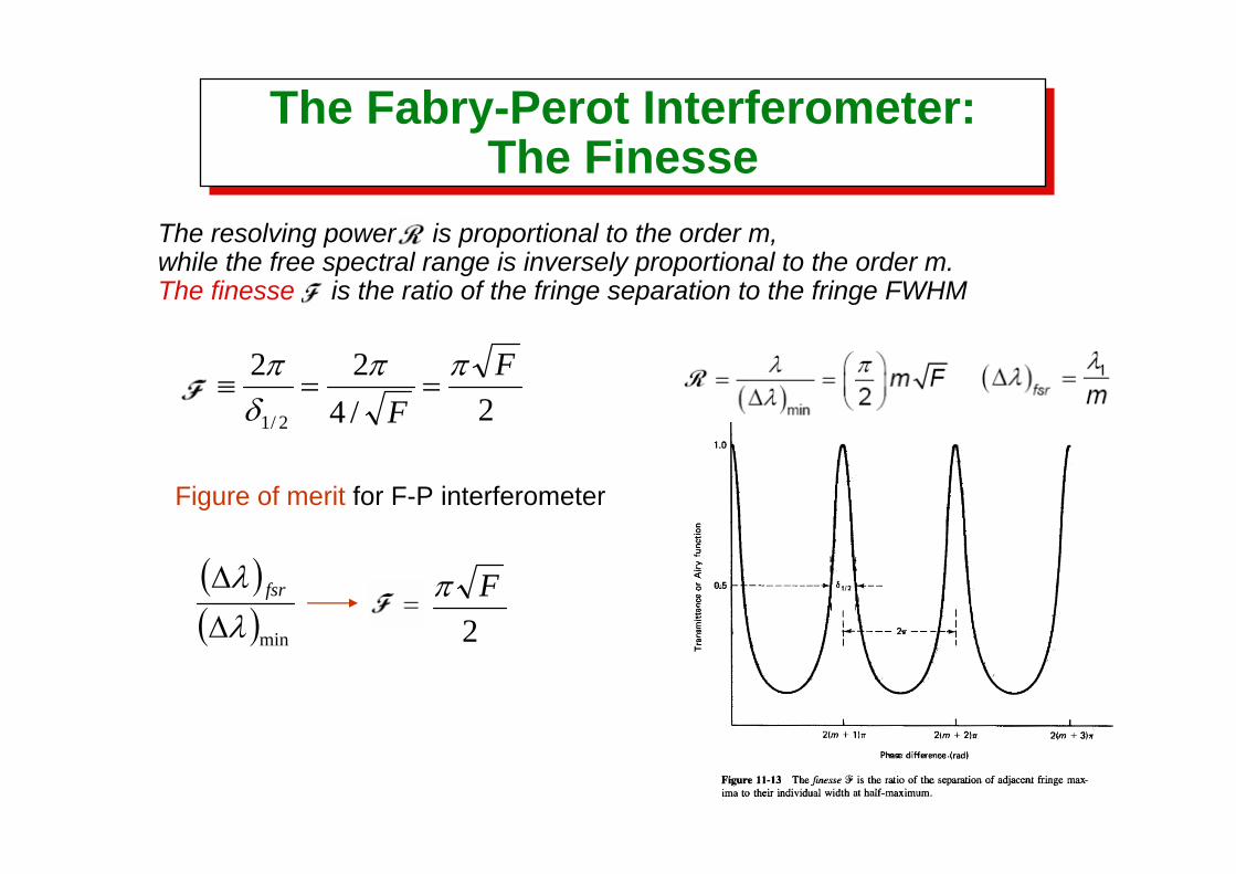
The Fabry-Perot Interferometer:The Finesse
The Fabry-Perot Interferometer:The Finesse
The resolving power is proportional to the order m,while the free spectral range is inversely proportional to the order m. The finesse is the ratio of the fringe separation to the fringe FWHM
2/422
2/1
FF
ππδ
π==≡
Figure of merit for F-P interferometer
2Fπ( )
( )minλλ
Δ
Δ fsr
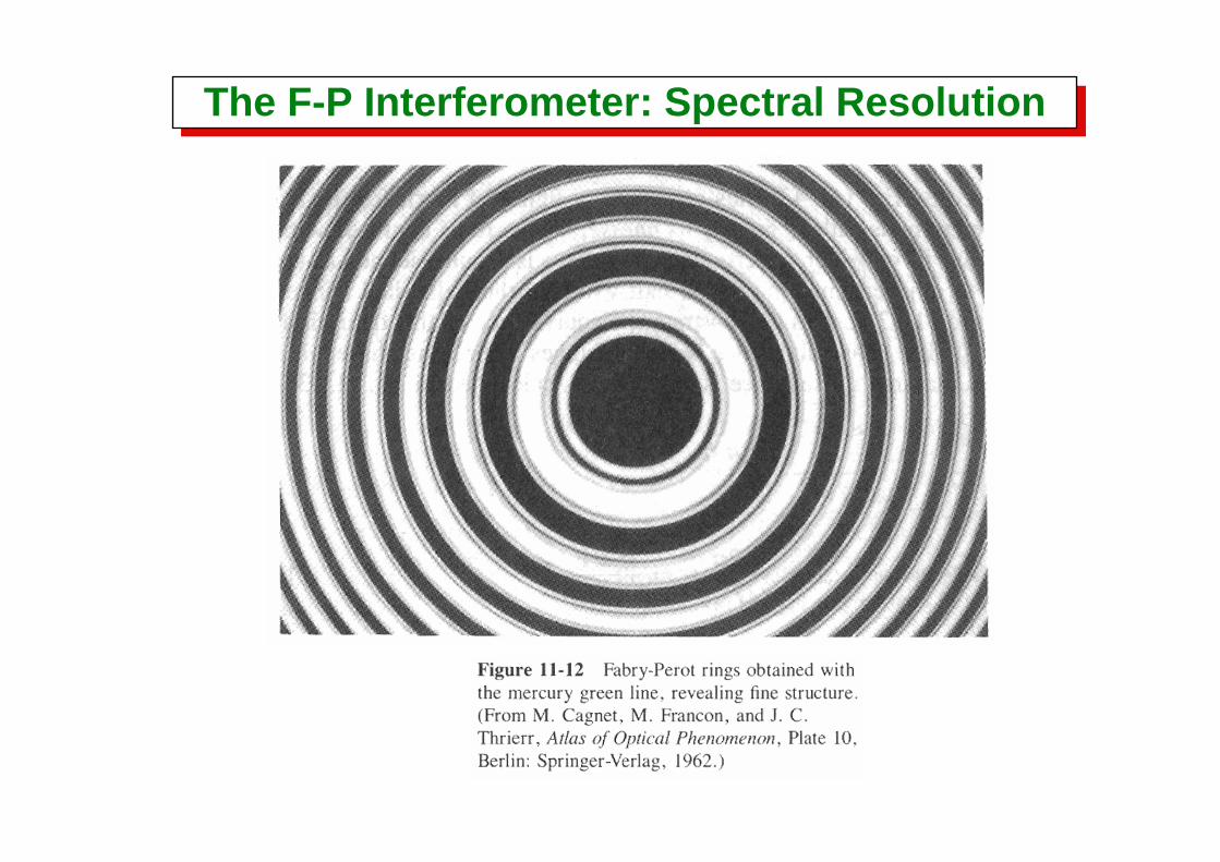
The F-P Interferometer: Spectral ResolutionThe F-P Interferometer: Spectral Resolution
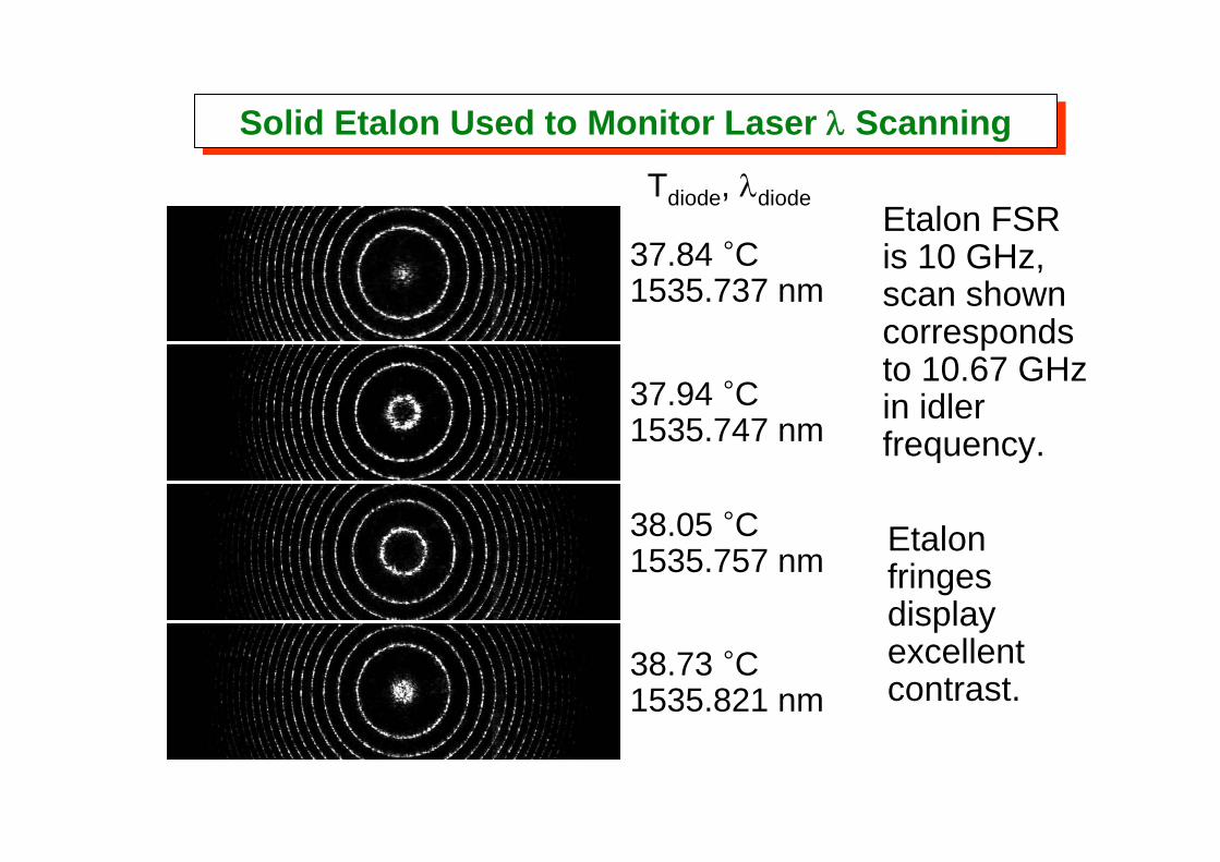
Tdiode, λdiode
37.84 °C1535.737 nm
37.94 °C1535.747 nm
38.05 °C1535.757 nm
38.73 °C1535.821 nm
Etalon FSRis 10 GHz, scan showncorrespondsto 10.67 GHzin idler frequency.
Etalon fringes display excellent contrast.
Solid Etalon Used to Monitor Laser λ ScanningSolid Etalon Used to Monitor Laser λ Scanning
Related Documents