Chapter 11 CPU Structure and Function

Chapter 11 CPU Structure and Function. CPU Structure CPU must: —Fetch instructions —Interpret instructions —Fetch data —Process data —Write data.
Jan 02, 2016
Welcome message from author
This document is posted to help you gain knowledge. Please leave a comment to let me know what you think about it! Share it to your friends and learn new things together.
Transcript
Chapter 11CPU Structure and Function

CPU Structure
• CPU must:—Fetch instructions—Interpret instructions—Fetch data—Process data—Write data
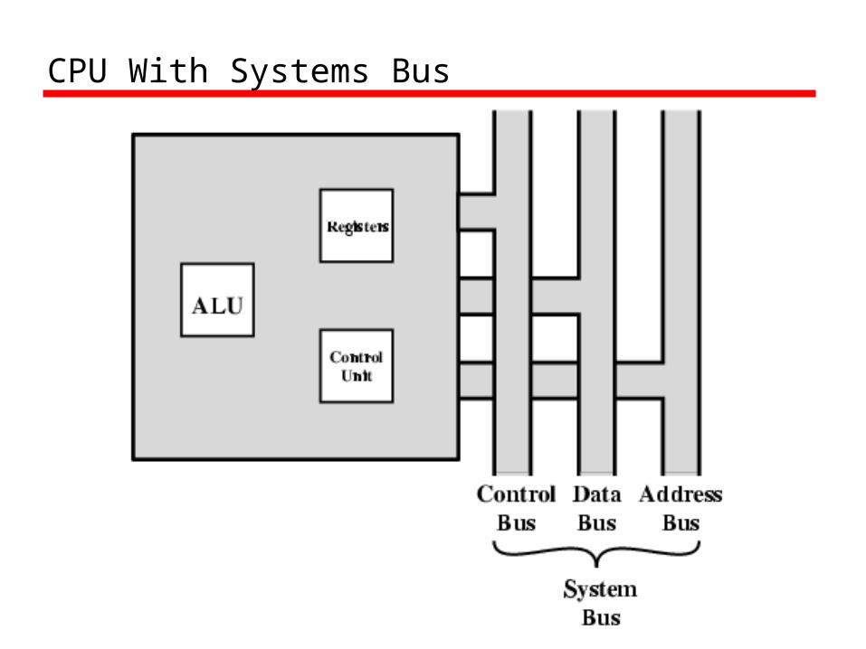
CPU With Systems Bus

CPU Internal Structure

Registers
• CPU must have some working space (temporary storage)
• Called registers• Number and function vary between
processor designs• One of the major design decisions• Top level of memory hierarchy

User Visible Registers
• General Purpose• Data• Address• Condition Codes

General Purpose Registers (1)
• May be true general purpose• May be restricted• May be used for data or addressing• Data
—Accumulator
• Addressing—Segment
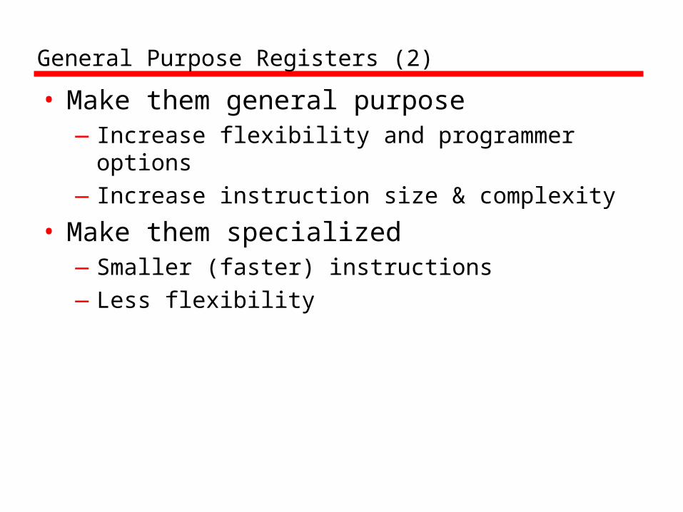
General Purpose Registers (2)
• Make them general purpose—Increase flexibility and programmer options—Increase instruction size & complexity
• Make them specialized—Smaller (faster) instructions—Less flexibility
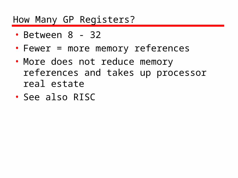
How Many GP Registers?
• Between 8 - 32• Fewer = more memory references• More does not reduce memory references
and takes up processor real estate• See also RISC
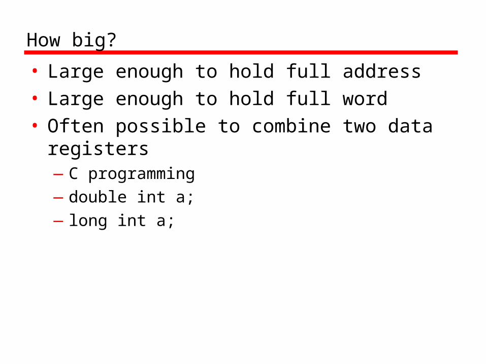
How big?
• Large enough to hold full address• Large enough to hold full word• Often possible to combine two data
registers—C programming—double int a;—long int a;

Condition Code Registers
• Sets of individual bits—e.g. result of last operation was zero
• Can be read (implicitly) by programs—e.g. Jump if zero
• Can not (usually) be set by programs
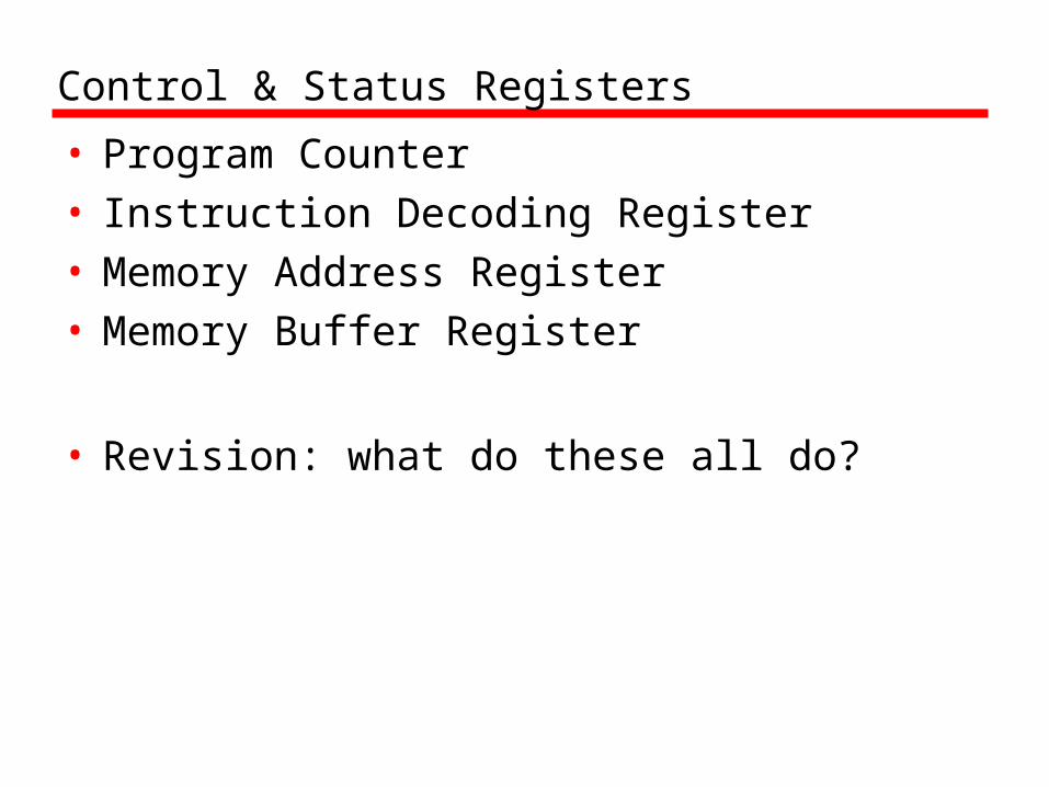
Control & Status Registers
• Program Counter• Instruction Decoding Register• Memory Address Register• Memory Buffer Register
• Revision: what do these all do?
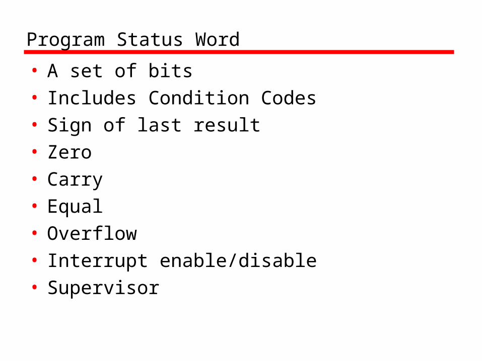
Program Status Word
• A set of bits• Includes Condition Codes• Sign of last result• Zero• Carry• Equal• Overflow• Interrupt enable/disable• Supervisor

Supervisor Mode
• Intel ring zero• Kernel mode• Allows privileged instructions to execute• Used by operating system• Not available to user programs

Other Registers
• May have registers pointing to:—Process control blocks (see O/S)—Interrupt Vectors (see O/S)
• N.B. CPU design and operating system design are closely linked
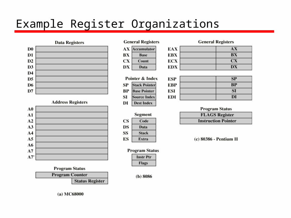
Example Register Organizations

Instruction Cycle
• Revision• Stallings Chapter 3

Indirect Cycle
• May require memory access to fetch operands
• Indirect addressing requires more memory accesses
• Can be thought of as additional instruction subcycle
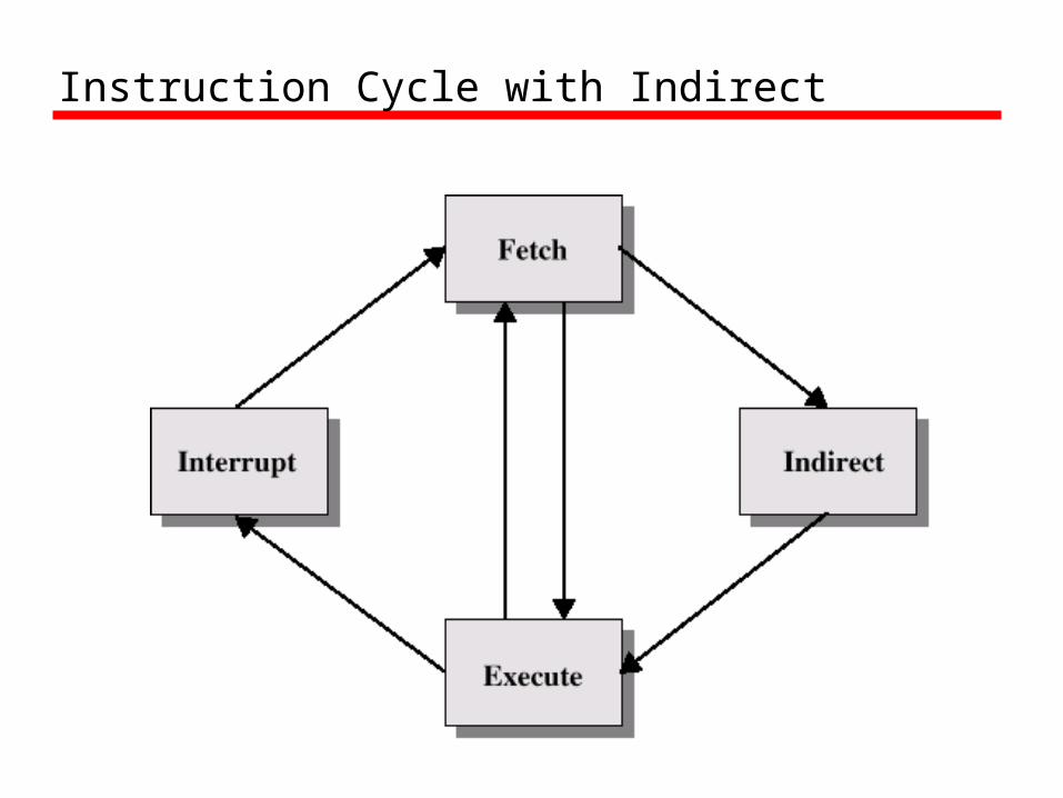
Instruction Cycle with Indirect
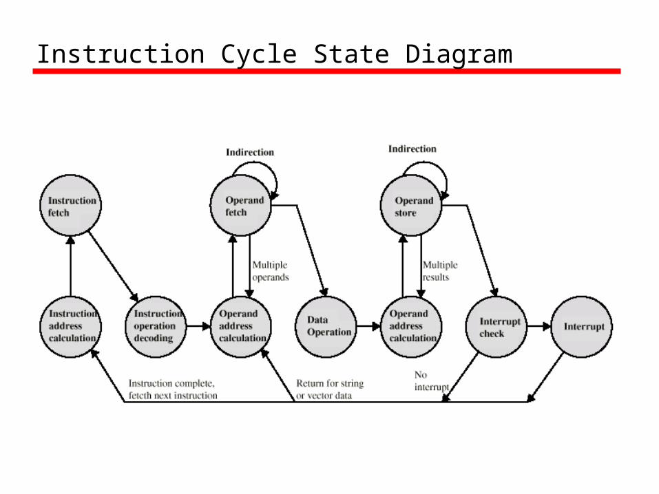
Instruction Cycle State Diagram
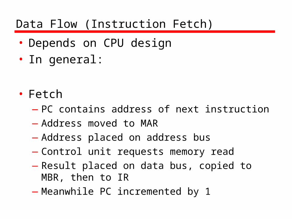
Data Flow (Instruction Fetch)
• Depends on CPU design• In general:
• Fetch—PC contains address of next instruction—Address moved to MAR—Address placed on address bus—Control unit requests memory read—Result placed on data bus, copied to MBR,
then to IR—Meanwhile PC incremented by 1
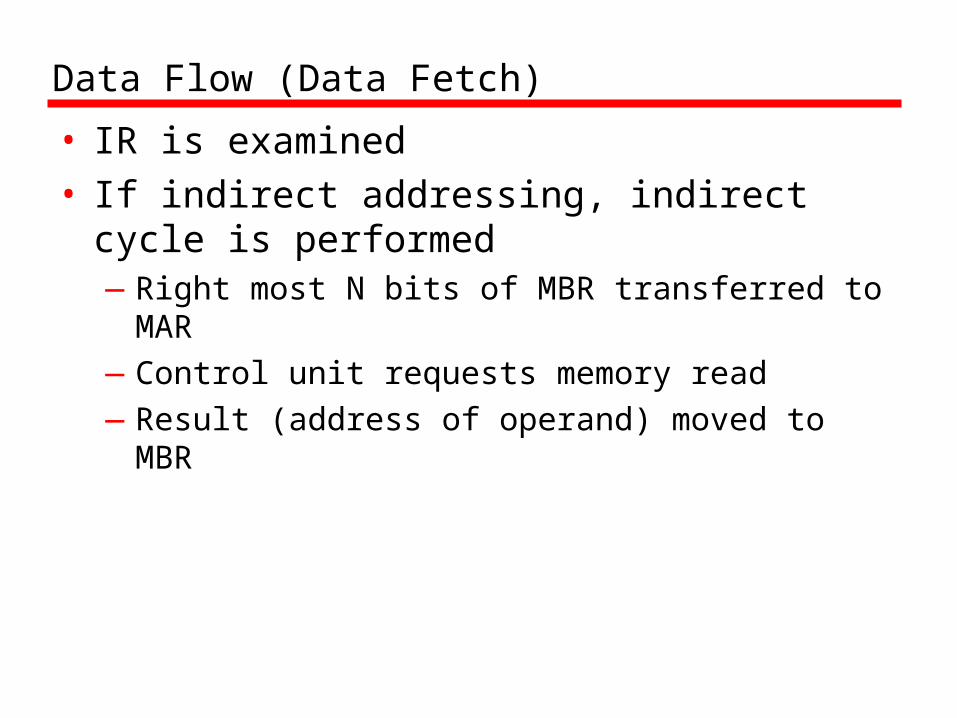
Data Flow (Data Fetch)
• IR is examined• If indirect addressing, indirect cycle is
performed—Right most N bits of MBR transferred to MAR—Control unit requests memory read—Result (address of operand) moved to MBR
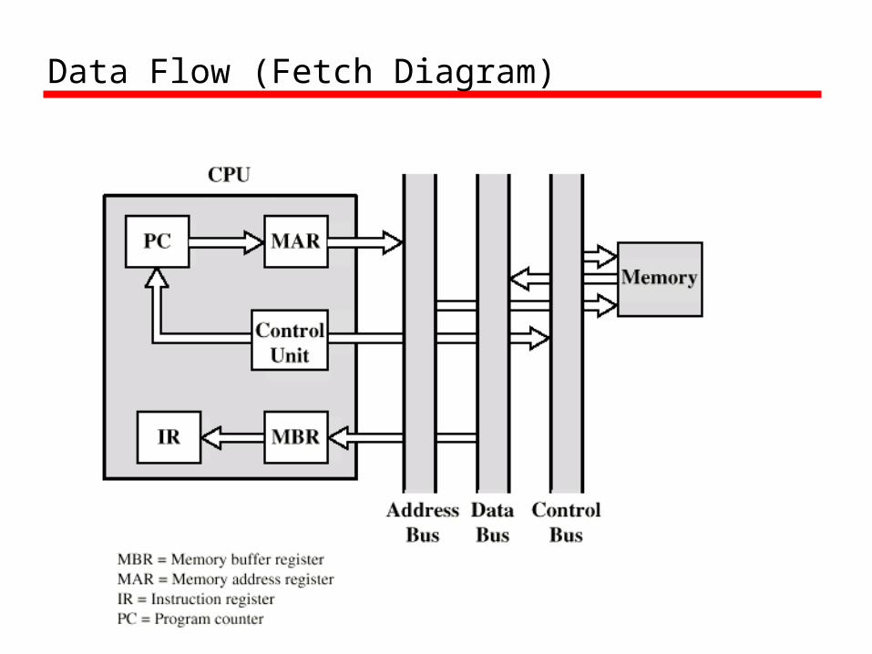
Data Flow (Fetch Diagram)

Data Flow (Indirect Diagram)

Data Flow (Execute)
• May take many forms• Depends on instruction being executed• May include
—Memory read/write—Input/Output—Register transfers—ALU operations
Data Flow (Interrupt)
• Simple• Predictable• Current PC saved to allow resumption
after interrupt• Contents of PC copied to MBR• Special memory location (e.g. stack
pointer) loaded to MAR• MBR written to memory• PC loaded with address of interrupt
handling routine• Next instruction (first of interrupt handler)
can be fetched

Data Flow (Interrupt Diagram)

Prefetch
• Fetch accessing main memory• Execution usually does not access main
memory• Can fetch next instruction during
execution of current instruction• Called instruction prefetch
Improved Performance
• But not doubled:—Fetch usually shorter than execution
– Prefetch more than one instruction?
—Any jump or branch means that prefetched instructions are not the required instructions
• Add more stages to improve performance
Pipelining
• Fetch instruction• Decode instruction• Calculate operands (i.e. EAs)• Fetch operands• Execute instructions• Write result
• Overlap these operations
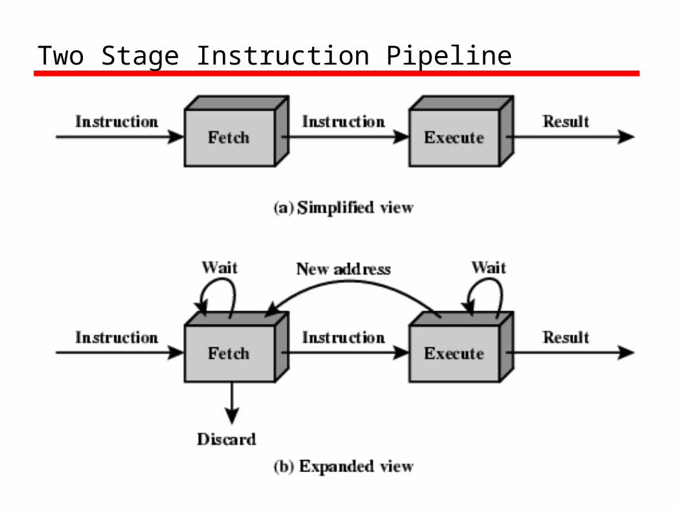
Two Stage Instruction Pipeline
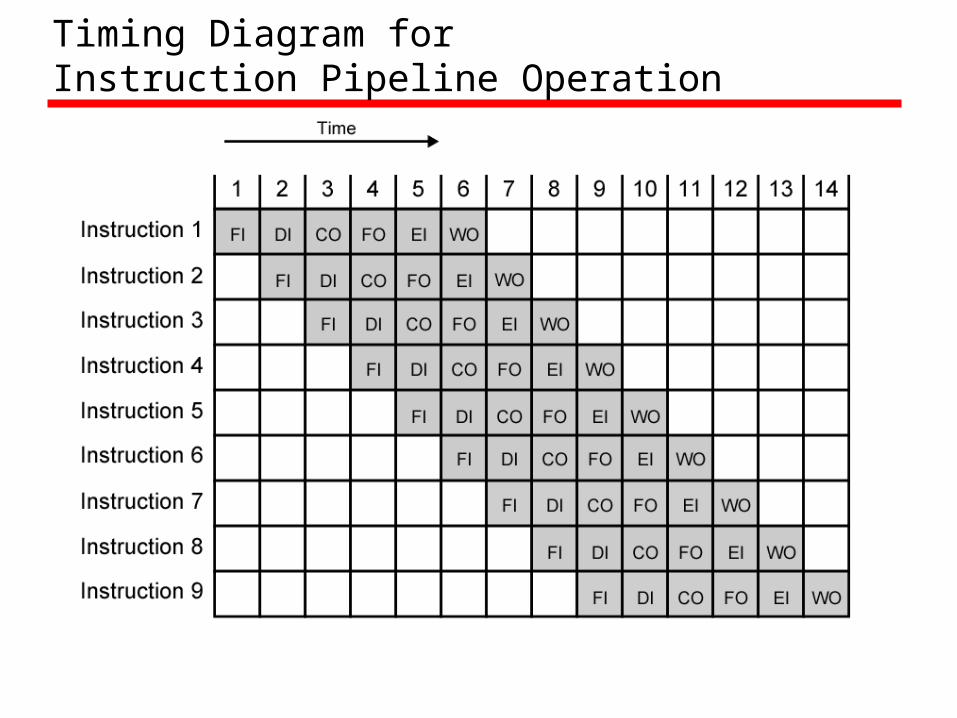
Timing Diagram for Instruction Pipeline Operation
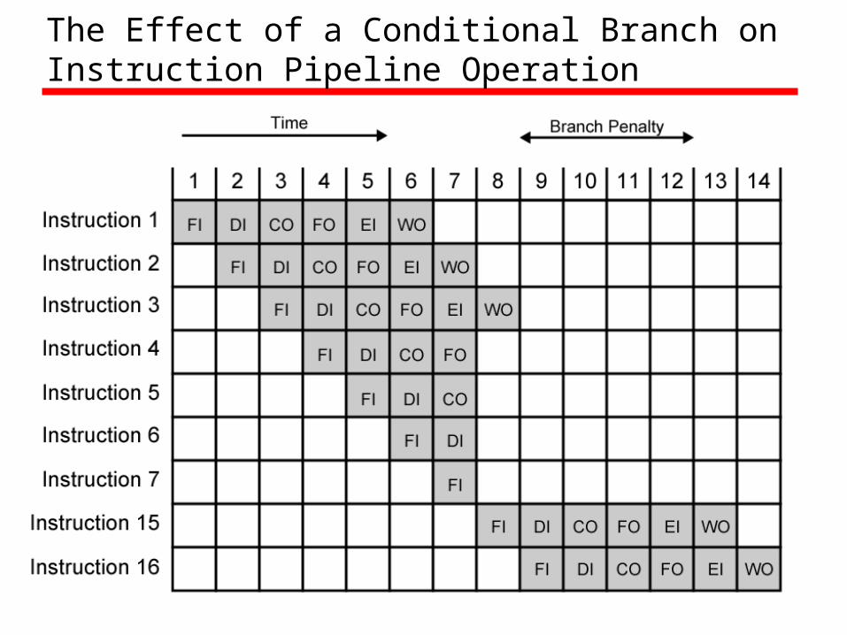
The Effect of a Conditional Branch on Instruction Pipeline Operation
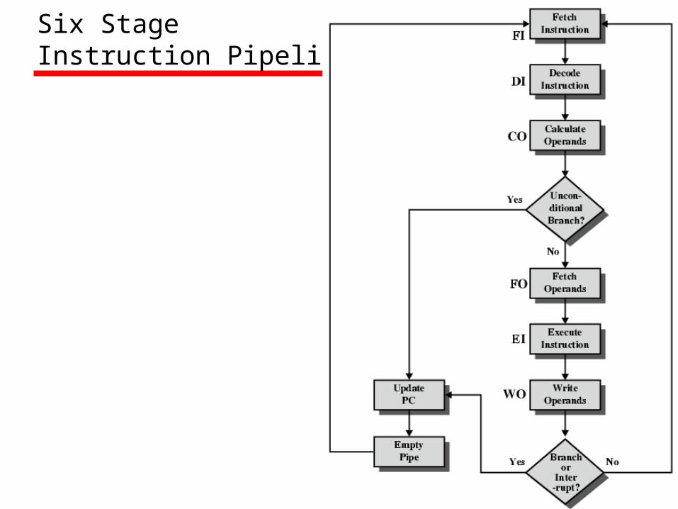
Six Stage Instruction Pipeline

Alternative Pipeline Depiction

Speedup Factorswith InstructionPipelining
Dealing with Branches
• Multiple Streams• Prefetch Branch Target• Loop buffer• Branch prediction• Delayed branching

Multiple Streams
• Have two pipelines• Prefetch each branch into a separate
pipeline• Use appropriate pipeline
• Leads to bus & register contention• Multiple branches lead to further pipelines
being needed
Prefetch Branch Target
• Target of branch is prefetched in addition to instructions following branch
• Keep target until branch is executed• Used by IBM 360/91

Loop Buffer
• Very fast memory• Maintained by fetch stage of pipeline• Check buffer before fetching from memory• Very good for small loops or jumps• c.f. cache• Used by CRAY-1
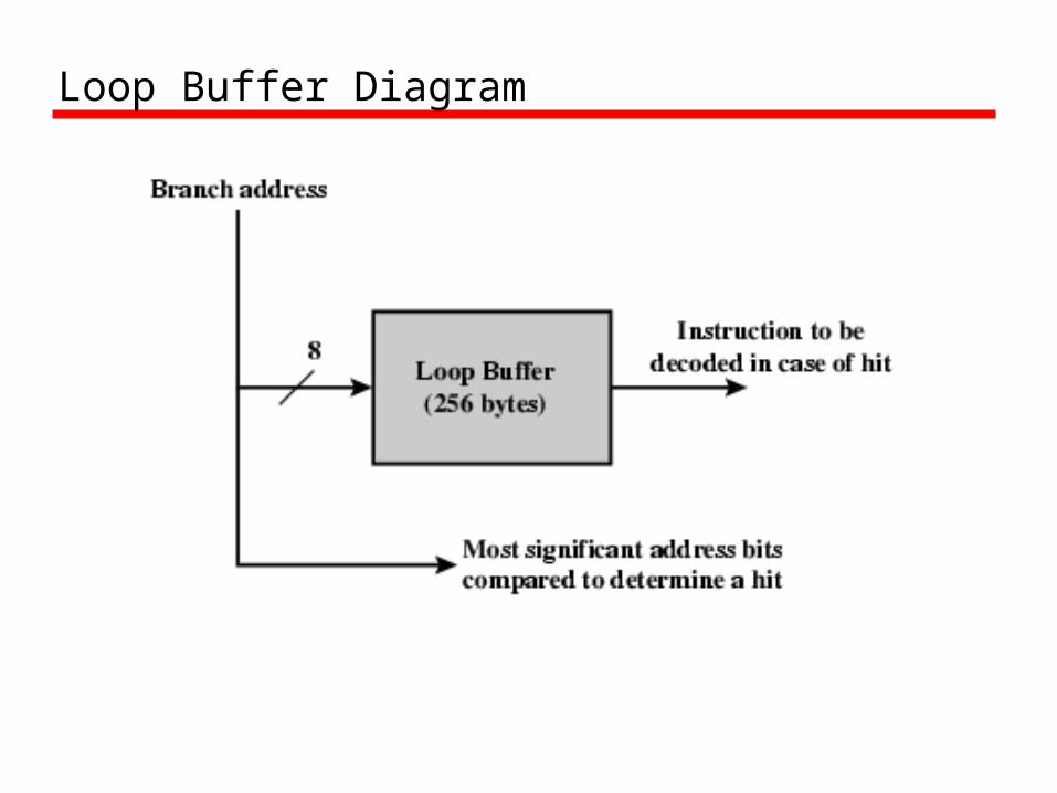
Loop Buffer Diagram
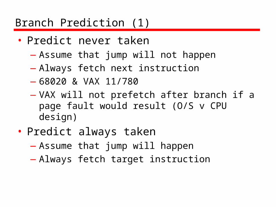
Branch Prediction (1)
• Predict never taken—Assume that jump will not happen—Always fetch next instruction —68020 & VAX 11/780—VAX will not prefetch after branch if a page
fault would result (O/S v CPU design)
• Predict always taken—Assume that jump will happen—Always fetch target instruction

Branch Prediction (2)
• Predict by Opcode—Some instructions are more likely to result in a
jump than thers—Can get up to 75% success
• Taken/Not taken switch—Based on previous history—Good for loops
Branch Prediction (3)
• Delayed Branch—Do not take jump until you have to—Rearrange instructions
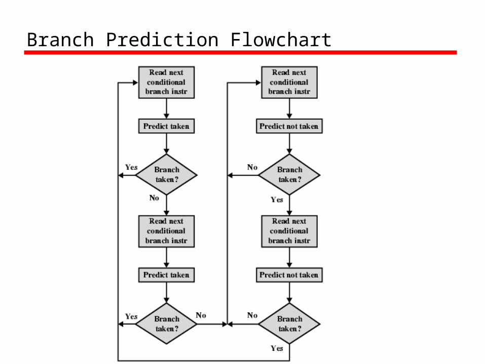
Branch Prediction Flowchart

Branch Prediction State Diagram
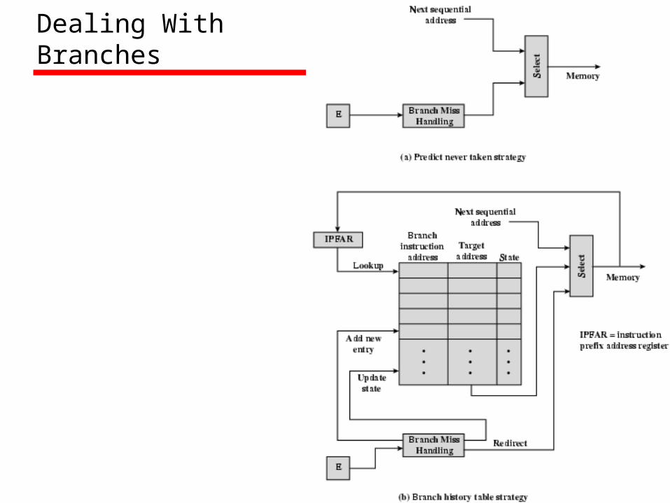
Dealing With Branches

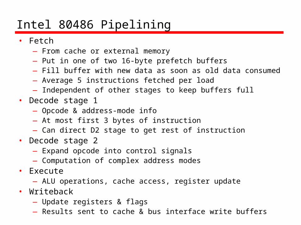
Intel 80486 Pipelining• Fetch
— From cache or external memory— Put in one of two 16-byte prefetch buffers— Fill buffer with new data as soon as old data consumed— Average 5 instructions fetched per load— Independent of other stages to keep buffers full
• Decode stage 1— Opcode & address-mode info— At most first 3 bytes of instruction— Can direct D2 stage to get rest of instruction
• Decode stage 2— Expand opcode into control signals— Computation of complex address modes
• Execute— ALU operations, cache access, register update
• Writeback— Update registers & flags— Results sent to cache & bus interface write buffers

80486 Instruction Pipeline Examples

Pentium 4 Registers

Cont..• General: there are eight 32-bit general-purpose regiser.
These may be used for all types of Pentium instruction; they can also hold operands for address calculations. Some of these registers also serve special purposes. For example, string instructions use the contents of the ECX, ESI and EDI registers as operands without having to reference these register explicitly in the instruction. As a result, a number of instructions can be encoded more compactly.
• Segment: The six 16-bit segment registers contain segment selectors, which index into segment tables. The code segment CS register references teh segment containing the instruction being executed. The stack segment SS register references the segment containing a user-visible stack. The remaining segment registers DS,ES,FS,GS enable the user to reference up to four separate data segments at a time.

Cont..
• Flags: The EFLAGS register contains condition codes and various mode bits.
• Instruction pointer: Contains the address of the current instructions. There are also the registers specifically devoted to the floating-point unit.
• Numeric: Each register holds an extended-precision 80bit floating point number. There are eight registers that function as a stack, with push and pop operations available in the instruction set.
• Control: The 16bit control register contains bits that control the operation of the floating point unit, including the type of rounding control; single,double, or extended precision; and bits to enable or disable various exception conditions.

Cont..
• Status: The 16bit status register contains bits that reflect the current state of the floating point unit, including a 3-bit pointer to the top of the stack; condition codes reporting the outcome of the last operation; and exception flags.
• Tag word: This 16bit register contains a 2bit tag for each floating point numeric register, which indicates the nature of the contents of the corresponding register. The four possible values are valid, zero,special and empty. These tags enable programs to check the contents of a numeric register without performing complex decoding of the actual data in the register. For example, when a context switch is made, the processor need not save any floating point register that are empty.

EFLAGS Register
Cont..
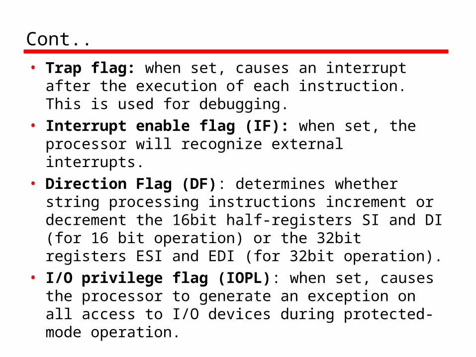
• Trap flag: when set, causes an interrupt after the execution of each instruction. This is used for debugging.
• Interrupt enable flag (IF): when set, the processor will recognize external interrupts.
• Direction Flag (DF): determines whether string processing instructions increment or decrement the 16bit half-registers SI and DI (for 16 bit operation) or the 32bit registers ESI and EDI (for 32bit operation).
• I/O privilege flag (IOPL): when set, causes the processor to generate an exception on all access to I/O devices during protected-mode operation.

Cont..
• Resume flag (RF): allows the programmer to disable debug exceptions so that the instruction can be restarted after a debug exception without immediately causing another debug exception.
• Alignment check (AC): Activates if a word or doubleword is addressed on a nonword or nondoubleword boundry .
• Identification flag (ID): If this bit can be set and cleared, then this processor supports the processorID instruction. This instruction provides information about the vendor, family and model.

Control Registers

Control register
• Protection enable (PE): Enable/disable protected mode of operation
• Monitor coprocessor (MP): Only of interest when running programs from earlier machines on the Pentium; it relates to the presence of an arithmetic coprocessor.
• Emulation (EM): set when the processor does not have a floating point unit, and causes an interrupt when an attempt is made to execute floating point instruction.
• Task switched (TS): Indicates that the processor has switched tasks.
• Extension type (ET): used to indicate support of math coprocessor instructions on earlier machines.
Cont..
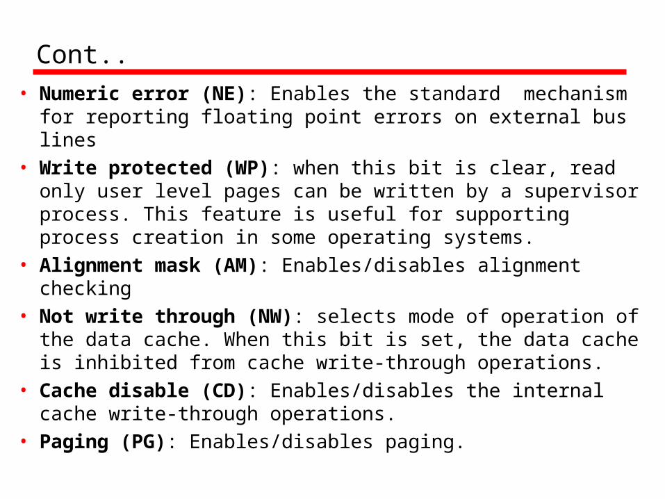
• Numeric error (NE): Enables the standard mechanism for reporting floating point errors on external bus lines
• Write protected (WP): when this bit is clear, read only user level pages can be written by a supervisor process. This feature is useful for supporting process creation in some operating systems.
• Alignment mask (AM): Enables/disables alignment checking
• Not write through (NW): selects mode of operation of the data cache. When this bit is set, the data cache is inhibited from cache write-through operations.
• Cache disable (CD): Enables/disables the internal cache write-through operations.
• Paging (PG): Enables/disables paging.

MMX Register Mapping
• MMX uses several 64 bit data types• Use 3 bit register address fields so that
eight MMX registers are supported. • No MMX specific registers
—Aliasing to lower 64 bits of existing floating point registers
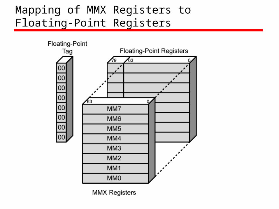
Mapping of MMX Registers to Floating-Point Registers
Key characteristics of MMX• Recall that the floating point registers are treated as a
stack for floating point operations. For MMX operations, these registers are accessed directly.
• The first time that an MMX instruction is executed after any floating-point operations, the FP tag word is marked valid. This reflects the change from stack operation to direct register addressing.
• The EMMS instruction sets bits of the FP tag word to indicate that all registers are empty. It is important that the programmer insert this instruction at the end of an MMX code block so that subsequent floating point operations function properly.
• When a value is written to an MMX register, bits[79:64] of the corresponding FP register are set to all ones. This set the value in the FP register to infinity when viewed as a floating point value. This ensures that an MMX data value will not look like a valid floating point value.
Pentium Interrupt Processing
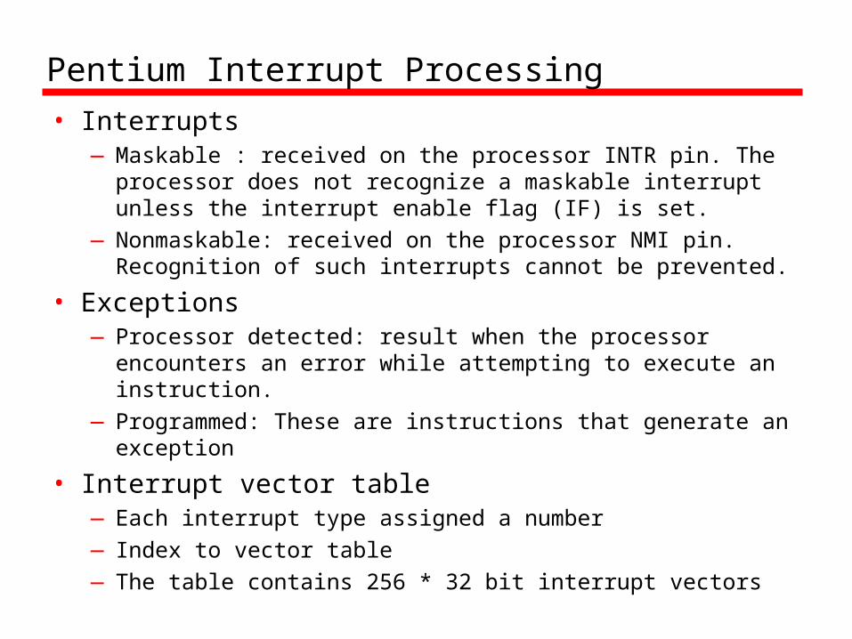
• Interrupts—Maskable : received on the processor INTR pin. The
processor does not recognize a maskable interrupt unless the interrupt enable flag (IF) is set.
—Nonmaskable: received on the processor NMI pin. Recognition of such interrupts cannot be prevented.
• Exceptions—Processor detected: result when the processor
encounters an error while attempting to execute an instruction.
—Programmed: These are instructions that generate an exception
• Interrupt vector table—Each interrupt type assigned a number—Index to vector table—The table contains 256 * 32 bit interrupt vectors

Cont..
• 5 priority classes• Class 1: Traps on the previous instruction (vector
1)• Class 2: External interrupts (2,32-255)• Class 3: Faults from fetching next instruction
(3,4)• Class 4: Faults from decoding the next instruction
(6,7)• Class 5: Faults on executing an instruction
Interrupt handling
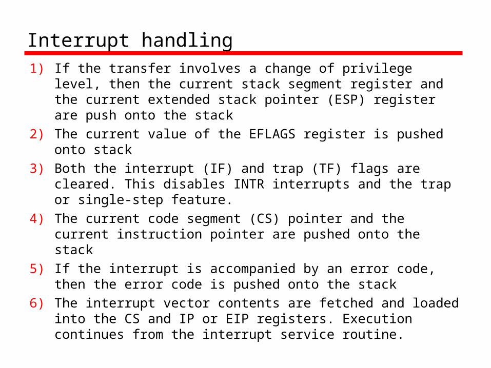
1) If the transfer involves a change of privilege level, then the current stack segment register and the current extended stack pointer (ESP) register are push onto the stack
2) The current value of the EFLAGS register is pushed onto stack
3) Both the interrupt (IF) and trap (TF) flags are cleared. This disables INTR interrupts and the trap or single-step feature.
4) The current code segment (CS) pointer and the current instruction pointer are pushed onto the stack
5) If the interrupt is accompanied by an error code, then the error code is pushed onto the stack
6) The interrupt vector contents are fetched and loaded into the CS and IP or EIP registers. Execution continues from the interrupt service routine.
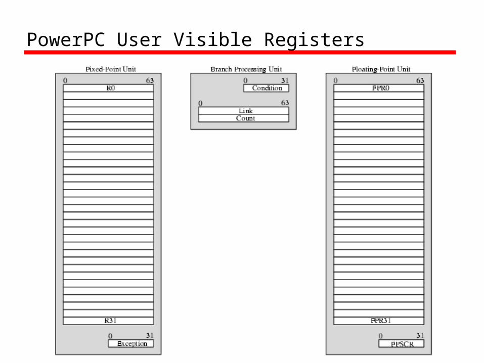
PowerPC User Visible Registers

Fixed-point unit includes the following:
• General: There are 32 64-bit general purpose register. These may be used to load, store, and manipulate data operands and may also be used for register indirect addressing. Register 0 is treated somewhat differently. For load and store operations and several of the add instructions, register 0 is treated as having a constant value zero regardless of its actual contents.
• Exception register (XER): Includes 3 bits that report exceptions in integer arithmetic operations. This register also includes a byte count field that is used as an operand for some string instructions

Floating point unit
• General: There are 32 64bit general purpose registers, used for all floating point operations.
• Floating point status and control register (FPSCR): This 32 bit register contains bits that control the operations of the floating-point unit and bits that record the status resulting from floating point operations.
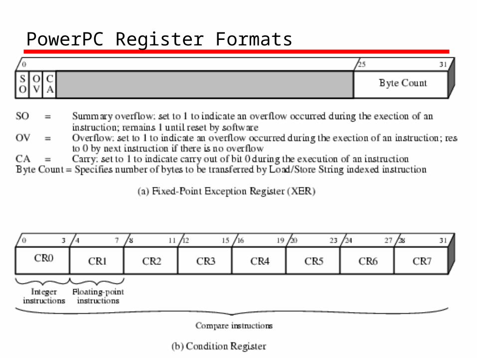
PowerPC Register Formats

Interrupt Processing

Interrupt Handling1) The processor places the address of the instruction to be
executed next in the save/restore register 0 (SRR0). This is the address of the currently executing instruction if the interrupt was caused by a failed attempt to execute that instruction; otherwise, it is the address of the next instruction to be executed after the current instruction.
2) The processor copies machine state information from the MSR to the save/restore Register 1 (SRR1). The bits that are depicted as unshaded in Table 12.7 (page 440) are copied. The remaining bits of SRR1 are loaded with information specific to the interrupt type.
3) The MSR is set to a hardware defined value specific to the interrupt type. For all interrupt types, address translation is turned off and external interrupt are disabled
4) The processor then transfer control to the appropriate interrupt handler. The address of the interrupt handlers are stored in the interrupt table (table 12.6). The base address of that table is determined by bit 57 of the MSR.
Related Documents


