Chapter 10 Systems Planning, Analysis, and Design

Chapter 10 Systems Planning, Analysis, and Design.
Dec 25, 2015
Welcome message from author
This document is posted to help you gain knowledge. Please leave a comment to let me know what you think about it! Share it to your friends and learn new things together.
Transcript

Chapter 10Systems Planning, Analysis, and
Design

Presentation Summary
I. The Steps of Systems Analysis
II. Fact-Gathering Techniques
III. Techniques for Organizing Facts
IV. Structured Systems Analysis
V. The Steps of Systems Design
I. The Steps of Systems Analysis
A. Survey the Present SystemB. Identify Information Needs
C. Identify System RequirementsD. Develop a Systems Analysis Report

A. Survey the Present System
Four objectives of the system survey are concerned with:
1. Understanding the Operational Aspects of the Current System
2. Establishing a Working Relationship with System Users
3. Collection of Data for Systems Design4. Identification of Specific System Problems

1. Understanding the Operational Aspects of the Current System
It is dangerous to try to modify an existing
system that you do not thoroughly understand.
The strengths and weaknesses of the
current system must be identified before
modifying the system.

2. Establishing a Working Relationship with System Users
Get to know the people involved in the system as soon as possible.
Communicate the benefits of the new system.Provide assurance, when possible, of job security and
no changes in job responsibilities.Project a genuine concern for making the life of the
system user better.
The success or failure of a systems project largely depends on the relationship between the development
team and the people who use the system.

3. Collection of Data for Systems Design
Internal data may be collected from sources
like interviews, questionnaires,
observations, and policy manuals.
Outside data may be collected from industry
publications, professional journals, and customers.

4. Identification of Specific System Problems
Effectiveness considers whether the system meets
its objectives.Efficiency determines
whether objectives are met at the lowest possible cost.Evaluation of the system
should also consider bottlenecks. These are
areas where small changes could result in major
improvements.

B. Identify Information NeedsIdentify the managers primary job responsibility.
Identify the means by which the manager is evaluated.
Identify some major problems the manager faces.
Identify the way the manager evaluates personal output.
Managers often have difficulty in expressing just how they make decisions. Identification of the above areas can
be helpful in pinpointing a manager’s decision process. Identification of problems may be best done by simply
getting the manager talking while you listen.

C. Identify the System Requirements
Requirements can be specified in terms of inputs and outputs.First determine the
required outputs that a manager needs to make
a decision.Then determine the
inputs and processing needed to generate the
outputs.

D. The Systems Analysis Report
Description of the overall problems in subsystem
being studiedRecommendations for
improving existing system or design of new system.Overall cost budget and timetable for project to
date.
The report should organize and document the first three phases of analysis. Some key elements of the
report include:

II. Fact-Gathering Techniques
A. Fact Gathering Through Interviews
B. Fact Gathering Through Questionnaires

A. Fact Gathering Through Interviews
1. Depth Interviews - Conversation is guided largely by
feelings and interest of the person being interviewed.
2. Structured Interviews - Useful after a depth interview for obtaining answers to a specific set of questions.

B. Fact Gathering Through Questionnaires
1. Open-Ended Questionnaires - Persons provide written
answers to general rather than specific questions.
2. Closed-End Questionnaires - Use for routine situations or
when a large number of similar individuals would be
questioned.
What types of information
do you use to make decisions?

III. Structured Systems Analysis
A. Structured Systems Analysis Defined
B. The Development of Logical Data Flow Diagrams
C. Defining Data Dictionaries
D. Defining Access Methods
E. Defining Process Logic

A. Structured Systems Analysis Defined
Structured systems analysis is a system of
documentation.
An approach to systems analysis that begins with a very general description of
a particular system, and then moves to ever
increasing detail ending with computer program code and other details.

B. The Development of Logical Data Flow Diagrams
1. Data Flow Diagram Levels
2. Data Flow Diagram Symbols
3. Data Flow Diagram Conventions

1. Data-Flow Diagram LevelsContext Diagrams represent the highest level of data-flow diagrams. More detail is provided in subsequent diagrams beginning at level zero.
0Purchasing
System
StoresStores Requisition
Purchase Order
Purchase Details PurchaseFile
PurchaseFile
Context Diagram
VendorsVendors

1. Data-Flow Diagram Levels
1.0Validate
Requisition
StoresStores Requisition
Details
Purchase Details PurchaseFile
PurchaseFile
VendorsVendors
2.0Prepare
PurchaseOrder
Purchase Order
(Continued)

2. Data-Flow Diagram Symbols
Sources and destinations of data and information are shown in rectangular symbols around the process
symbol.
Process symbol(s) in center of diagram identify system(s) under investigation.
Data flow lines describe the input data to the system and the output reports from the system.

3. Data Flow Diagram Conventions
Each process must have at least one input data flow and one output data flow.
A data flow has at least one end connected to a process
A diagram should not contain more than seven processes before being leveled into
more detailed diagrams.

C. Defining Data Dictionaries
The data dictionary corresponds to the data stores referenced in the logical data flow
diagrams. This involves giving a description of the data structure and data
elements involved.

D. Defining Access MethodsIt is necessary to specify how data stores will be accessed.
This typically involves defining primary and secondary access keys. For example, in the purchase file the “account-no-1” may serve as the primary key and
“person responsible” as the secondary key.
Purchase File DescriptionAccount – Identifiers account-no-1 … primary account number account-no-2 … secondary account number person-responsible … person in charge of account
Financial-Information account-balance … current balance last – purchase … most recent transaction

E. Defining Process Logic
There are a number of different approaches to documenting the process logic, including decision trees
and structured English.
Structured English is a special language for describing process logic that uses several key words, including IF,
THEN, ELSE IF, and SO.
Structured English does not include provisions for error conditions and data file access. If these are added, the
resulting documentation is pseudocode. See pseudocode for a C++ program on the following slide.
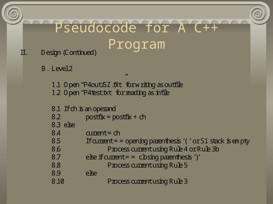
Pseudocode for A C++ ProgramII. Design (Continued)
B. Level 2
1.1 Open “P4outJSZ.txt” for writing as outfile 1.2 Open “P4test.txt” for reading as infile 8.1 If ch is an operand 8.2 postfix = postfix + ch 8.3 else 8.4 current = ch 8.5 If current = = opening parenthesis ‘( ‘ or S1 stack is empty 8.6 Process current using Rule 4 or Rule 3b 8.7 else if current = = closing parenthesis ‘)’ 8.8 Process current using Rule 5 8.9 else 8.10 Process current using Rule 3

V. Steps in Systems Design
A. Evaluation of Design AlternativesB. Preparation of Detailed Design
SpecificationsC. Preparation of Systems Design Report

A. Evaluation of Design Alternatives
There are usually a number of attractive solutions that could be chosen.
Completely new systems may be designed from scratch or a pre-made system could be
recommended.Alternative systems should be documented with
information concerning advantages/disadvantages and cost information.
A given system must be feasible from both an operational and technical perspective.

B. Preparation of Detailed Design SpecificationsReports and
Other OutputsReports and
Other Outputs
DatabaseDesignDatabaseDesign
SpecifyProcessing
SpecifyProcessing
SpecifyInputsSpecifyInputs
ControlConsiderations
ControlConsiderations
3. Once these decisions have been made, the designer then builds in
the appropriate controls.
2. Once all the outputs are specified, the data inputs and processing steps
are automatically determined.
1. Working with system objectives, the designer should design all management reports
and operational output documents.

C. Preparation of Systems Design Report
The completed design specifications should
take the form of a proposal.
Contents include timetables for
completion, a budget, personnel requirements,
and diagrams of the system to be implemented.

Summary
Four Steps of Systems Analysis
Gathering Information Through Interviews and Questionnaires
Structured Systems Analysis as a Form of Documentation
Detailed Design Specifications
Related Documents