City of Tacoma 2012 SWMM Chapter 10 3- 115 Volume 3 Chapter 10 Material Specifications 10.1 Pipe Specifications Pipe systems are networks of storm drain pipes, catch basins, manholes, inlets, and outfalls, designed and constructed to convey stormwater. 10.1.1 Pipe Materials All pipe material, joints, and protective treatments shall be in accordance with Section 9.05 of the latest version of the WSDOT/APWA Standard Specifications and AASHTO and ASTM treatment standards as amended and as provided in this manual by the City of Tacoma, or the City of Tacoma Public Works master specifications. 10.1.1.1 Pipes Within Right-of-Way All storm drainage pipe to be installed in public right-of-way, that will be publicly maintained, or privately owned but located within the right-of-way shall be either: • Rubber-gasketed concrete pipe (12-inch maximum diameter), or • Rubber gasketed reinforced concrete pipe, minimum 12-inch diameter, or • Polyvinyl chloride (PVC) sewer pipe (ASTM D3034 SDR35 for PVC less than or equal to 15-inches or ASTM F679 for PVC greater than 15-inch) per City of Tacoma Public Works Master Specifications, or • Smooth interior, watertight, corrugated high-density polyethylene pipe (CPEP). Smooth interior CPEP shall have watertight joints meeting ASTM D3212 with gaskets meeting the requirements of ASTM F477. 4-inch through 10-inch pipe shall meet AASHTO M252, Type S; and 12-inch through 60-inch pipe shall meet AASHTO M294, Type S or ASTM F2306. All CPEP fittings shall conform to AASHTO M252, AASHTO M294, or ASTM F2306. • High-density polyethylene pipe (HDPE). Pipe must comply with requirement of Type III C5P34 per ASTM D1248 and have the PPI recommended designation of PE3408 and have an ASTM D3350 cell classification of 345434C or 345534C. Pipe shall have a manufacturer’s recommended hydrostatic design stress rating of 800 psi based on a material with a 1600 psi design basis determined in accordance with ASTM D2837-69. Pipe shall have a suggested design working pressure of 50 psi at 73.4 degrees F and SDR of 17.5. Designs utilizing HDPE pipe shall include considerations of the material’s thermal expansion/contraction properties for anchoring. • Ductile iron (class 50 or 52). Galvanized, aluminized, and/or corrugated iron or steel pipes are not allowed within the public right-of-way or as a connection to the Municipal system. 10.1.1.2 Private Pipes Outside the Right-of-Way In addition to the pipe materials listed in Section 10.1.1.2, privately owned pipe located outside the right-of-way may also be one of the following: • Corrugated aluminum pipe (12-gauge or thicker) • Aluminum spiral rib pipe (12-gauge or thicker) • Aluminized Type 2 corrugated steel (meeting AASHTO treatment M274 and M 56, 12- gauge or thicker)

Welcome message from author
This document is posted to help you gain knowledge. Please leave a comment to let me know what you think about it! Share it to your friends and learn new things together.
Transcript

City of Tacoma 2012 SWMM
Chapter 10 3- 115 Volume 3
Chapter 10 Material Specifications
10.1 Pipe SpecificationsPipe systems are networks of storm drain pipes, catch basins, manholes, inlets, and outfalls, designed and constructed to convey stormwater.
10.1.1 Pipe MaterialsAll pipe material, joints, and protective treatments shall be in accordance with Section 9.05 of the latest version of the WSDOT/APWA Standard Specifications and AASHTO and ASTM treatment standards as amended and as provided in this manual by the City of Tacoma, or the City of Tacoma Public Works master specifications.
10.1.1.1 Pipes Within Right-of-WayAll storm drainage pipe to be installed in public right-of-way, that will be publicly maintained, or privately owned but located within the right-of-way shall be either:
• Rubber-gasketed concrete pipe (12-inch maximum diameter), or
• Rubber gasketed reinforced concrete pipe, minimum 12-inch diameter, or
• Polyvinyl chloride (PVC) sewer pipe (ASTM D3034 SDR35 for PVC less than or equal to 15-inches or ASTM F679 for PVC greater than 15-inch) per City of Tacoma Public Works Master Specifications, or
• Smooth interior, watertight, corrugated high-density polyethylene pipe (CPEP). Smooth interior CPEP shall have watertight joints meeting ASTM D3212 with gaskets meeting the requirements of ASTM F477. 4-inch through 10-inch pipe shall meet AASHTO M252, Type S; and 12-inch through 60-inch pipe shall meet AASHTO M294, Type S or ASTM F2306. All CPEP fittings shall conform to AASHTO M252, AASHTO M294, or ASTM F2306.
• High-density polyethylene pipe (HDPE). Pipe must comply with requirement of Type III C5P34 per ASTM D1248 and have the PPI recommended designation of PE3408 and have an ASTM D3350 cell classification of 345434C or 345534C. Pipe shall have a manufacturer’s recommended hydrostatic design stress rating of 800 psi based on a material with a 1600 psi design basis determined in accordance with ASTM D2837-69. Pipe shall have a suggested design working pressure of 50 psi at 73.4 degrees F and SDR of 17.5. Designs utilizing HDPE pipe shall include considerations of the material’s thermal expansion/contraction properties for anchoring.
• Ductile iron (class 50 or 52).
Galvanized, aluminized, and/or corrugated iron or steel pipes are not allowed within the public right-of-way or as a connection to the Municipal system.
10.1.1.2 Private Pipes Outside the Right-of-WayIn addition to the pipe materials listed in Section 10.1.1.2, privately owned pipe located outside the right-of-way may also be one of the following:
• Corrugated aluminum pipe (12-gauge or thicker)
• Aluminum spiral rib pipe (12-gauge or thicker)
• Aluminized Type 2 corrugated steel (meeting AASHTO treatment M274 and M 56, 12-gauge or thicker)

2012 SWMM City of Tacoma
Volume 3 3- 116 Chapter 10
• Corrugated high density polyethylene pipe (CPEP) - single wall, fully corrugated meeting AASHTO standard M-252 (permitted only outside public right-of-way and for use in temporary storm sewer systems and as downspout/footing/yard drain collectors on private property)
• Polyvinyl chloride (PVC) sewer pipe (SDR 35, meeting requirements of ASTM D3034)
10.1.2 Pipe Sizes• Pipe sizes for pipe systems to be maintained by the City of Tacoma shall be 12-inch, 15-
inch, 18-inch, 21-inch, 24-inch, and 30-inch. For pipes larger than 30-inch increasing increments of 6-inch intervals shall be used (36-inch, 42-inch, 48-inch, etc.).
• Pipes smaller than 12-inch may only be used for privately maintained systems, or to match the diameter of existing downstream mains, or as approved in writing by Environmental Services.
• Catch basin leads shall be a minimum of 12-inch.
• Roof drains may use pipe as small as 3-inch, and small driveway drains may use pipe as small as 6-inch. Pipes under 10-inch may require capacity analysis if requested by Environmental Services.
10.1.3 Changes in Pipe Sizes• Pipe direction changes or size increases or decreases are only allowed at manholes and
catch basins.
• Where a minimal fall is necessary between inlet and outlet pipes in a structure, pipes must be aligned vertically by one of the following in order of preference:
a. Match pipe crowns
b. Match 80% diameters of pipes
c. Match pipe inverts or use City approved drop inlet connection
10.1.4 Pipe Alignment and Depth• Pipes must be laid true to line and grade with no curves, bends, or deflections in any
direction.
Exception: Vertical deflections in HDPE and ductile iron pipe with flanged restrained mechanical joint bends (not greater than 30%) on steep slopes are allowed provided the pipe adequately drains with a minimum velocity of 2 feet per second (fps).
• A break in grade or alignment or changes in pipe material shall occur only at catch basins or manholes.
• For the standard main alignment refer to the Public Works Design Manual.
• The standard depth for new mains measures six (6) feet from the center of the pipe to the main street surface.
• The project engineer shall consult with the City for the potential of a future extension of the storm system. In this case, the City may require modifications to the depth or alignment.
• Connections to the storm system shall be made at a structure. Tributary connections shall be made at 90° to the main. Slight variations may be allowed.

City of Tacoma 2012 SWMM
Chapter 10 3- 117 Volume 3
• Pipes shall be allowed to cross under retaining walls as specifically approved in writing by Environmental Services when no other reasonable alternatives exist.
10.1.5 Pipe Slopes and Velocities• The slope of the pipe shall be set so that a minimum velocity of 2 feet per second can be
maintained at full flow.
• A minimum slope for all pipes shall be 0.5%. Slopes less than 0.5% may be allowed on a case-by-case basis provided calculations are provided to demonstrate that a minimum velocity of 2 feet per second can be maintained at full flow.
• Maximum slopes, velocities, and anchor spacings are shown in Table 3 - 19. If velocities exceed 15 feet per second for the conveyance system design event described in Chapter 9, provide anchors and/or restrained joints at bends and junctions.
10.1.6 Pipes on Steep SlopesNOTE: This section does not apply to catch basin leads that utilize a single pipe
section. Typically, below-ground installations do not require anchors. Consult with Environmental Services for steep below-ground installations.
• A basis of design shall be required for all mains installed at a slope greater than 20%.
• Slopes 20% or greater shall require all drainage to be piped from the top to the bottom of the slope in High Density Polyethylene (HDPE) pipe (butt-fused) or ductile iron pipe welded or mechanically restrained. Additional anchoring design is required for these pipes.
• Above-ground installation is required on slopes greater than 40% to minimize disturbance to steep slopes, unless otherwise approved in writing by Environmental Services.
• HDPE pipe systems longer than 100 feet must be anchored at the upstream end if the slope exceeds 20% or as required by Environmental Services.
• Above ground installations of HDPE shall address the high thermal expansion/contraction coefficient of the pipe material. An analysis shall be completed to demonstrate that the system as designed will tolerate the thermal expansion of the pipe material.
Table 3 - 19: Maximum Pipe Slopes, Velocities and Anchor Requirements
Pipe MaterialsPipe Slope Above Which Pipe Anchors Required and Minimum Anchor Spacing
Max Slope Allowed
Max.Velocity Full Flow
Spiral Rib(1), PVC(1),
CPEP-singlewall
20%
(1 anchor per 100 L.F. of pipe)30%(3) 30 fps
Concrete(1) or CPEP-
smooth interior(1)10%
(1 anchor per 50 L.F. of pipe)20%(3) 30 fps
Ductile Iron(4) 40%
(1 anchor per pipe section)None None
HDPE(2)
50%
(1 anchor per 100 L.F. of pipe – cross slope installations may be allowed with additional anchoring and analysis)
None None
Notes:(1) Not allowed in landslide hazard areas.(2) Butt-fused pipe joints required. Above-ground installation is required on slopes greater than 40% to minimize disturbance to steep slopes.(3) Maximum slope of 200% allowed for these pipe materials with no joints (one section) if structures are provided at each end and the pipes are property grouted or otherwise restrained to the structures.(4) Restrained joints required on slopes greater than 25%. Above-ground installation is required on slopes greater than 40% to minimize disturbance to steep slopes.
Key: PVC = Polyvinyl chloride pipe CPEP = Corrugated high density polyethylene pipe HDPE = High density polyethylene pipe
2012 SWMM City of Tacoma
Volume 3 3- 118 Chapter 10
10.1.7 Pipe Clearances
Horizontal
A minimum of 5 feet horizontal separation shall be maintained between the storm main and all water, sanitary sewer mains or other storm mains. This also applies to laterals within the right-of-way that run parallel to mains. Horizontal separation on private property shall comply with applicable building codes, plumbing codes, fire codes, and Tacoma Water requirements. Separation must also comply with proper bedding requirements.
Vertical
Where crossing an existing or proposed utility or sanitary sewer main, the alignment of the storm system shall be such that the two systems cross as close to perpendicular as possible. Where crossing a sanitary sewer main, provide a minimum 18 inches of vertical separation. For crossings of water mains contact Tacoma Water. The minimum vertical separation for a storm main crossing any other utility shall be 6 inches.
NOTE: Where the vertical separation of two parallel systems exceeds the horizontal separation, additional horizontal separation may be required to provide future access to the deeper system.

City of Tacoma 2012 SWMM
Chapter 10 3- 119 Volume 3
For crossings with other utilities, contact each individual utility for separation.
10.1.8 Pipe Cover• Suitable pipe cover over storm pipes in road rights-of-way shall be calculated for H-20
loading by the Project Engineer. Pipe cover is measured from the finished grade elevation down to the top of the outside surface of the pipe. Pipe manufacturer’s recommendations are acceptable if verified by the Project Engineer.
• Minimum cover for all pipe types shall be three feet in areas subject to vehicular traffic unless manufacturer’s recommendations or calculations are provided from the Professional Engineer to demonstrate that the pipe can withstand less cover. Cover shall be measured from the top edge of the pipe to the final grade.
• Pipe cover in areas not subject to vehicular loads, such as landscape planters and yards, may be reduced to a 1-foot minimum.
10.2 Culvert SpecificationsCulverts are relatively short segments of pipe of circular, elliptical, rectangular, or arch cross section and typically convey flow under road embankments or driveways. Culverts installed in stream and natural drainages shall meet the City’s Critical Areas Preservation Ordinance and any fish passage requirements of the Washington State Department of Fish and Wildlife.
10.2.1 Inlets and OutletsAll inlets and outlets in or near roadway embankments must be flush with and conforming to the slope of the embankments.
• For culverts 18-inch diameter and larger, the embankment around the culvert inlet shall be protected from erosion by rock lining or riprap as specified in Table 3 - 21, except the length shall extend at least 5 feet upstream of the culvert, and the height shall be at or above the design headwater elevation.
• Inlet structures, such as concrete headwalls, may provide a more economical design by allowing the use of smaller entrance coefficients and, hence, smaller diameter culverts. When properly designed, they will also protect the embankment from erosion and eliminate the need for rock lining.
• In order to maintain the stability of roadway embankments, concrete headwalls, wingwalls, or tapered inlets and outlets may be required if right-of-way or easement constraints prohibit the culvert from extending to the toe of the embankment slopes. All inlet structures or headwalls installed in or near roadway embankments must be flush with and conforming to the slope of the embankment.
• Debris barriers (trash racks) are required on the inlets of all culverts that are over 60 feet in length and are 12 to 36 inches in diameter. This requirement also applies to the inlets of pipe systems. See Figure 3 - 32 for a debris barrier detail. Exceptions are culverts on Type 1 or 2 streams.
• For culverts 18-inch diameter and larger, the receiving channel of the outlet shall be protected from erosion by rock lining specified in Table 3 - 21, except the height shall be one foot above maximum tailwater elevation or one foot above the crown per Figure 3 - 35, whichever is higher.
• Closed depressions are required to have two outlets in the event one outlet clogs. This could be a second outlet pipe or an emergency spillway.
2012 SWMM City of Tacoma
Volume 3 3- 120 Chapter 10
10.3 Open Channel Specifications
10.3.1 Natural ChannelsNatural channels are defined as those that have occurred naturally due to the flow of surface waters, or those that, although originally constructed by human activity, have taken on the appearance of a natural channel including a stable route and biological community. They may vary hydraulically along each channel reach and should be left in their natural condition, wherever feasible or required, in order to maintain natural hydrologic functions and wildlife habitat benefits from established vegetation.
10.3.2 Constructed ChannelsConstructed channels are those constructed or maintained by human activity and include bank stabilization of natural channels. Constructed channels shall be either vegetation-lined, rock lined, or lined with appropriately bioengineered vegetation.
• Vegetation-lined channels are the most desirable of the constructed channels when properly designed and constructed. The vegetation stabilizes the slopes of the channel, controls erosion of the channel surface, and removes pollutants. The channel storage, low velocities, water quality benefits, and greenbelt multiple-use benefits create significant advantages over other constructed channels. The presence of vegetation in channels creates turbulence, which results in loss of energy and increased flow retardation; therefore, the design engineer must consider sediment deposition and scour, as well as flow capacity, when designing the channel.
• Rock-lined channels are necessary where a vegetative lining will not provide adequate protection from erosive velocities. They may be constructed with riprap, gabions, or slope mattress linings. The rock lining increases the turbulence, resulting in a loss of energy and increased flow retardation. Rock lining also permits a higher design velocity and therefore a steeper design slope than in grass-lined channels. Rock linings are also used for erosion control at culvert and storm drain outlets, sharp channel bends, channel confluences, and locally steepened channel sections.
• Bioengineered vegetation lining is a desirable alternative to the conventional methods of rock armoring. Soil bioengineering is a highly specialized science that uses living plants and plant parts to stabilize eroded or damaged land. Properly designed bioengineering systems are capable of providing a measure of immediate soil protection and mechanical reinforcement. As the plants grow they produce vegetative protective cover and a root reinforcing matrix in the soil mantle. This root reinforcement serves several purposes:
a. The developed anchor roots provide both shear and tensile strength to the soil, thereby providing protection from the frictional shear and tensile velocity components to the soil mantle during the time when flows are receding and pore pressure is high in the saturated bank.
b. The root mat provides a living filter in the soil mantle that allows for the natural release of water after the high flows have receded.
c. The combined root system exhibits active friction transfer along the length of the living roots. This consolidates soil particles in the bank and serves to protect the soil structure from collapsing and the stabilization measures from failing.

City of Tacoma 2012 SWMM
Chapter 10 3- 121 Volume 3
10.3.3 Open Channel Design Criteria• Open channels shall be designed to provide required conveyance capacity while
minimizing erosion and allowing for aesthetics, habitat preservation, and enhancement. See Section 9.3 for open channel sizing criteria.
• An access easement for maintenance is required along all constructed channels located on private property. Required easement widths and building setback lines vary with channel top width.
• Channel cross-section geometry shall be trapezoidal, triangular, parabolic, or segmental as shown in Figure 3 - 36 through Figure 3 - 38. Side slopes shall be no steeper than 3:1 for vegetation-lined channels and 2:1 for rock-lined channels.
• Vegetation-lined channels shall have bottom slope gradients of 6% or less and a maximum velocity at design flow of 5 fps (see Table 3 - 20).
• Rock-lined channels or bank stabilization of natural channels shall be used when design flow velocities exceed 5 feet per second. Rock stabilization shall be in accordance with Table 3 - 20 or stabilized with bioengineering methods as described above in “Constructed Channels.”
10.4 Structures All structures to be maintained by the City of Tacoma shall meet the requirements of the Public Works Design Manual. All other structures must meet WSDOT standards.
The following criteria shall be used when designing a conveyance system that utilizes catch basins or manholes:
• Connections to the storm system shall be made at a structure. Tributary connections shall be made at 90° to the main. Slight variations may be allowed.
• The design event per Chapter 9 must be analyzed for proposed catch basin installations when grate capacity is a concern. The maximum surface run between catch basins shall not exceed 550 feet.
• Catch basin (or manhole) diameter shall be determined by pipe diameter and orientation at the junction structure. A plan view of the junction structure, drawn to scale, will be required when more than four pipes enter the structure on the same plane, or if angles of approach and clearance between pipes is of concern. The plan view (and sections if necessary) must demonstrate a minimum 8-inch interior distance between knockouts for 48-inch, 54-inch and 60-inch manholes, and a 12-inch interior distance between knockouts for 72-inch to 120-inch manholes.
• Type 1 & Type 1L basin height shall not exceed eight (8) feet.
• Type 2 (48-inch minimum diameter) catch basins or manholes shall be used at the following locations or for the following situations:
◦ When overall structure height exceeds 8 feet.
◦ When all pipes tying into the structure exceed the limits set for Type 1 structures.
◦ All Type 2 catch basins shall be specifically approved by Environmental Services.
• Catch basin grates shall be vaned grates.
• Quarry spalls shall not be placed around inlets, to accomodate maintenance.
• The maximum slope of ground surface for a radius of 5 feet around a catch basin grate shall be 3:1. The preferred slope is 5:1 to facilitate maintenance access.

2012 SWMM City of Tacoma
Volume 3 3- 122 Chapter 10
• Catch basin (or manhole) evaluation of structural integrity for H-20 loading will be required for multiple junction catch basins and other structures that exceed the recommendations of the manufacturers. Environmental Services may require further review for determining structural integrity.
• Catch basins leads shall be no longer than 50 feet unless specifically approved by Environmental Services.
• Catch basins shall be located:
◦ Such that the inlet is placed next to the face of the curb and at an elevation to collect stormwater runoff (the structure offset shown on the plans shall be to center of grate, not center of structure to ensure grate location is appropriate);
◦ At the low point of any sag vertical curve or grade break where the grade of roadway transitions from a negative to a positive grade;
◦ Prior to any intersection such that a minimal amount of water flows across the intersection, through a curb ramp, or around a street return;
◦ Prior to transitions from a typical crown to a full warp through a downhill grade;
◦ Upstream of curb ramps outside of the wing of the curb ramp.
• Catch basins shall not be located:
◦ In areas of expected pedestrian traffic;
◦ In crosswalks;
◦ In the wheel path of vehicles;
◦ In driveways;
◦ In graveled areas or high sediment generating areas unless pretreatment per Volume 5 is provided;
◦ Where they will conflict with other utilities.
• All catch basins, inlets, etc. shall be marked as follows:
“Dump no waste. Drains to stream.”or
“Dump no waste. Drains to Sound.”
• The maximum surface run between manholes shall not exceed 350 linear feet.
• Changes in pipe direction, or increases or decreases in size, shall only be allowed at structures.
• For pipe slope less than the required minimum, distance between structures shall be decreased to 200 linear feet.
• For Type 1and 1L, catch basin to catch basin connections shall not be allowed.
• Bubble up systems shall not be allowed.

City of Tacoma 2012 SWMM
Chapter 10 3- 123 Volume 3
10.5 System Connections• Connections to a pipe system shall be made only at catch basins or manholes. No wyes
or tees are allowed except on private roof/footing/yard drain systems on pipes 8 inches in diameter, or less. Where wyes and tees are utilized, clean-outs shall be required upstream of each wye and tee.
• Extensions of catch basin leads shall connect to the same pipe type, or replacement of the lead or addition of a structure is required.
• A flexible pipe-to-manhole connector shall be utilized in all connections of rigid and flexible pipes to new precast concrete manholes to provide a watertight joint between the pipe and manhole. The connector shall be “Kor-N-Seal” with “Wedge Korband” or Engineer-approved equivalent.
• Connections to catch basins shall use sand collars.
• Connections to structures and mains shall be at 90°. Slight variations may be allowed.
• Fall through manhole structures shall be 0.1 foot. Pipes of different diameters shall be aligned vertically in manholes by one of the following methods, listed in order of preference:
a. Match pipe crowns
b. Match 80% diameters of pipes.
c. Match pipe inverts or use City approved drop inlet connection.
• Where inlet pipes are significantly higher than outlet pipes special design features may be required.
• Drop connections shall be allowed for catch basin leads only. Catch basin leads shall connect below the cone of the manhole.
• Private connections to the City storm system shall be at a drainage structure (i.e. catch basin or manhole) and only if capacity exists at the design storm event. Tee connections into the side of a pipe shall not be permitted.
• Roof downspouts may be infiltrated or dispersed in accordance with the provisions of Chapter 2. Infiltration and dispersion shall be evaluated first. If infiltration and dispersion are not feasible, roof drains may be discharged through the curb per Section 2.8 into the roadway gutter or connected into a drainage structure. Roof downspouts may not be connected directly into the side of a storm drainage pipe.
2012 SWMM City of Tacoma
Volume 3 3- 124 Chapter 10
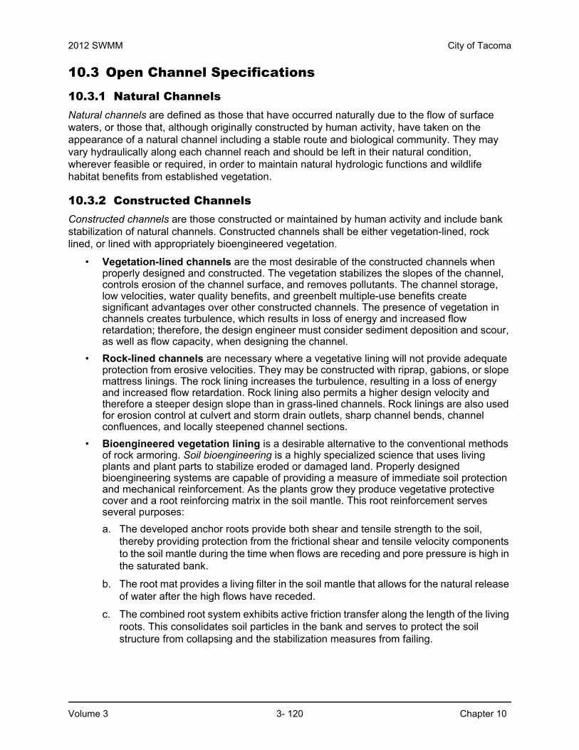
10.6 Debris BarriersTrash racks on City-owned pipes are only required for culverts, pond outlet pipes or as otherwise directed by Environmental Services. Debris barriers (trash racks) are required on all pipes entering a pipe system. See Figure 3 - 32 for required debris barriers on pipe ends outside of roadways and for requirements on pipe ends (culverts) projecting from driveways or roadway side slopes.
Figure 3 - 32. Debris Barrier
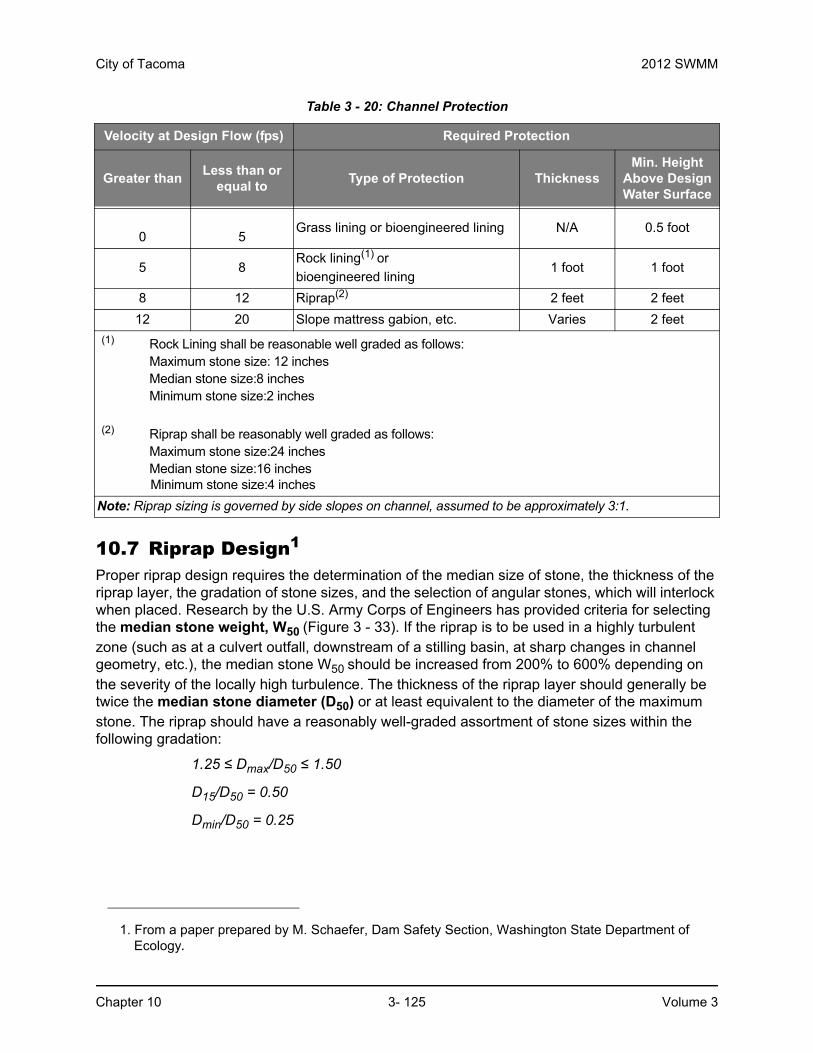
Table 3 - 20: Channel Protection
Velocity at Design Flow (fps) Required Protection
Greater thanLess than or
equal toType of Protection Thickness
Min. Height Above Design Water Surface
0 5Grass lining or bioengineered lining N/A 0.5 foot
5 8Rock lining(1) or
bioengineered lining1 foot 1 foot
8 12 Riprap(2) 2 feet 2 feet
12 20 Slope mattress gabion, etc. Varies 2 feet
(1) Rock Lining shall be reasonable well graded as follows:Maximum stone size: 12 inchesMedian stone size:8 inchesMinimum stone size:2 inches
(2) Riprap shall be reasonably well graded as follows:Maximum stone size:24 inchesMedian stone size:16 inches
Minimum stone size:4 inches
Note: Riprap sizing is governed by side slopes on channel, assumed to be approximately 3:1.
City of Tacoma 2012 SWMM
Chapter 10 3- 125 Volume 3
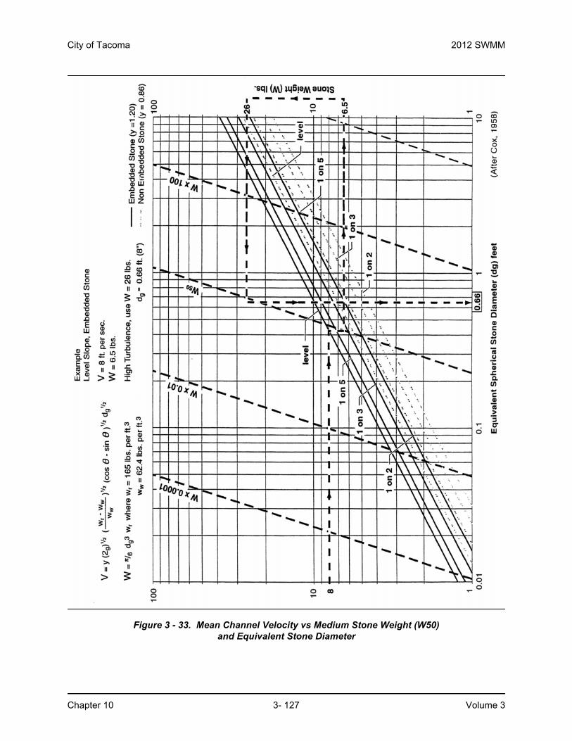
10.7 Riprap Design1
Proper riprap design requires the determination of the median size of stone, the thickness of the riprap layer, the gradation of stone sizes, and the selection of angular stones, which will interlock when placed. Research by the U.S. Army Corps of Engineers has provided criteria for selecting the median stone weight, W50 (Figure 3 - 33). If the riprap is to be used in a highly turbulent zone (such as at a culvert outfall, downstream of a stilling basin, at sharp changes in channel geometry, etc.), the median stone W50 should be increased from 200% to 600% depending on the severity of the locally high turbulence. The thickness of the riprap layer should generally be twice the median stone diameter (D50) or at least equivalent to the diameter of the maximum stone. The riprap should have a reasonably well-graded assortment of stone sizes within the following gradation:
1.25 ≤ Dmax/D50 ≤ 1.50
D15/D50 = 0.50
Dmin/D50 = 0.25
1. From a paper prepared by M. Schaefer, Dam Safety Section, Washington State Department of Ecology.

2012 SWMM City of Tacoma
Volume 3 3- 126 Chapter 10
Riprap Filter Design
Riprap should be underlain by a sand and gravel filter (or filter fabric) to keep the fine materials in the underlying channel bed from being washed through the voids in the riprap. Likewise, the filter material must be selected so that it is not washed through the voids in the riprap. Adequate filters can usually be provided by a reasonably well graded sand and gravel material where:
D15 < 5d85
The variable d85 refers to the sieve opening through which 85% of the material being protected will pass, and D15 has the same interpretation for the filter material. A filter material with a D50 of 0.5 mm will protect any finer material including clay. Where very large riprap is used, it is sometimes necessary to use two filter layers between the material being protected and the riprap.
Example:
What embedded riprap design should be used to protect a streambank at a level culvert outfall where the outfall velocities in the vicinity of the downstream toe are expected to be about 8 fps.
From Figure 3 - 33, W50 = 6.5 lbs, but since the downstream area below the outfall will be subjected to severe turbulence, increase W50 by 400% so that:
W50 = 26 lbs, D50 = 8.0 inches
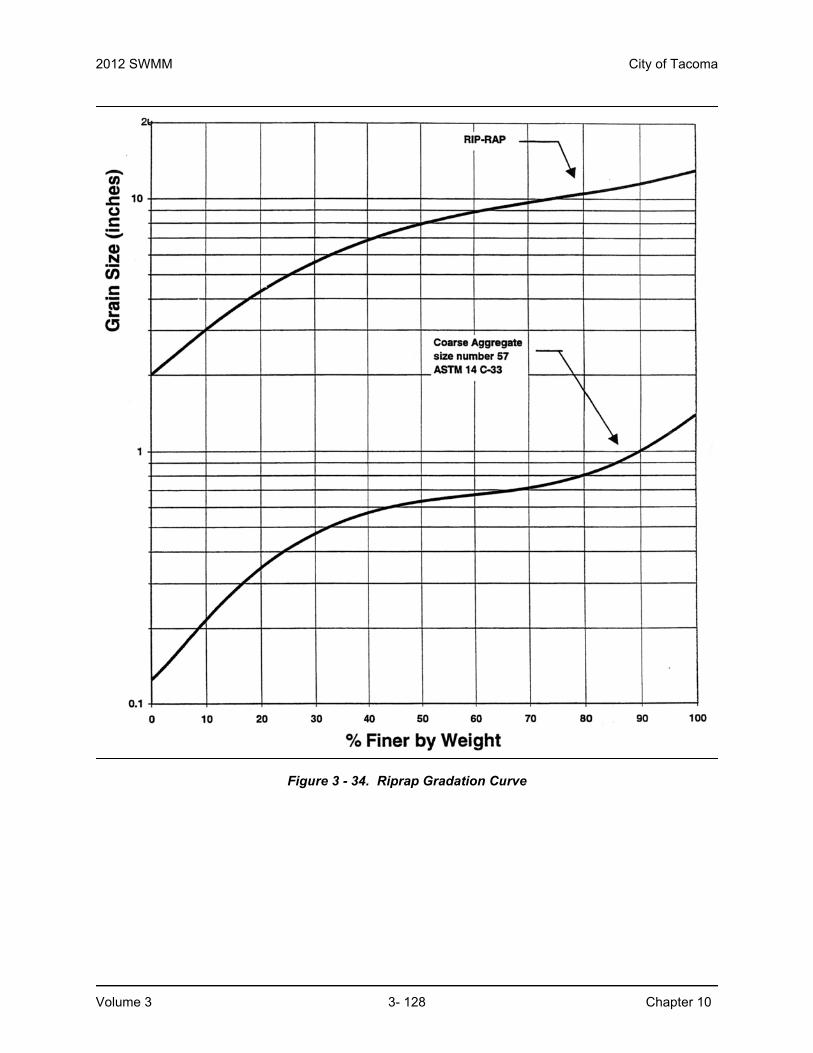
The gradation of the riprap is shown in Figure 3 - 34, and the minimum thickness would be 1 foot (from Table 3 - 20); however, 16 inches to 24 inches of riprap thickness would provide some additional insurance that the riprap will function properly in this highly turbulent area.
Table 3 - 34 shows that the gradation curve for ASTM C33, size number 57 coarse aggregate (used in concrete mixes), would meet the filter criteria. Applying the filter criteria to the coarse aggregate demonstrates that any underlying material whose gradation was coarser than that of concrete sand would be protected.
For additional information and procedures for specifying filters for riprap, refer to the Army Corps of Engineers Manual EM 1110-2-1601, Hydraulic Design of Flood Control Channels, Paragraph 14, “Riprap Protection.”
City of Tacoma 2012 SWMM
Chapter 10 3- 127 Volume 3
Figure 3 - 33. Mean Channel Velocity vs Medium Stone Weight (W50)and Equivalent Stone Diameter
2012 SWMM City of Tacoma
Volume 3 3- 128 Chapter 10
Figure 3 - 34. Riprap Gradation Curve
Related Documents