Chapter 10 – Digital System Projects Using HDL Copyright © 2011, 2007, 2004, 2001, 1998 by Pearson Education, Inc. Upper Saddle River, New Jersey 07458.
Dec 18, 2015
Welcome message from author
This document is posted to help you gain knowledge. Please leave a comment to let me know what you think about it! Share it to your friends and learn new things together.
Transcript


Chapter 10 – Digital System Projects Using HDL

Digital Systems: Principles and Applications, 11/eRonald J. Tocci, Neal S. Widmer, Gregory L. Moss
Copyright © 2011, 2007, 2004, 2001, 1998 by Pearson Education, Inc.Upper Saddle River, New Jersey 07458 • All rights reserved
• Selected areas covered in this chapter:– Analyzing operation of systems made of several
components covered earlier in this textbook.– Describing an entire project with one HDL file.– Describing the process of hierarchical project
management.– Dividing a project into manageable pieces.– Using Quartus II software tools to implement a
hierarchical modular project.– Developing strategies to test the operation of
digital circuits.
Chapter 10 Objectives

Digital Systems: Principles and Applications, 11/eRonald J. Tocci, Neal S. Widmer, Gregory L. Moss
Copyright © 2011, 2007, 2004, 2001, 1998 by Pearson Education, Inc.Upper Saddle River, New Jersey 07458 • All rights reserved
10-1 Small Project Management
• Hardware description languages were created for management of large digital systems: – Documentation, simulation testing & synthesis of working
circuits. • The Altera software tools are specifically designed
to work with managing projects.
• The general steps are:– Overall definition.– Strategic planning to break the project into
small pieces.– Synthesis and testing of each piece.– System integration and testing.

Digital Systems: Principles and Applications, 11/eRonald J. Tocci, Neal S. Widmer, Gregory L. Moss
Copyright © 2011, 2007, 2004, 2001, 1998 by Pearson Education, Inc.Upper Saddle River, New Jersey 07458 • All rights reserved
10-1 Small Project Management
• Definition of the project:– How many bits of data are needed?– How many devices are controlled by the outputs?– What are the names of each input and output?– Are the inputs and outputs active-HIGH or
active-LOW?– What are the speed requirements?– Do I fully understand how this should operate?– What will define successful completion of the
project?

Digital Systems: Principles and Applications, 11/eRonald J. Tocci, Neal S. Widmer, Gregory L. Moss
Copyright © 2011, 2007, 2004, 2001, 1998 by Pearson Education, Inc.Upper Saddle River, New Jersey 07458 • All rights reserved
10-1 Small Project Management
• In the strategy for dividing the project into manageable pieces, requirements are:– There must be a way to test each piece.– They must fit together to make up the whole system.– We must know the nature of all the signals that
interconnect the pieces.– The exact operation of each block must be thoroughly
defined and understood.– We must have a clear vision of how to make
each block work.
Digital Systems: Principles and Applications, 11/eRonald J. Tocci, Neal S. Widmer, Gregory L. Moss
Copyright © 2011, 2007, 2004, 2001, 1998 by Pearson Education, Inc.Upper Saddle River, New Jersey 07458 • All rights reserved
10-1 Small Project Management
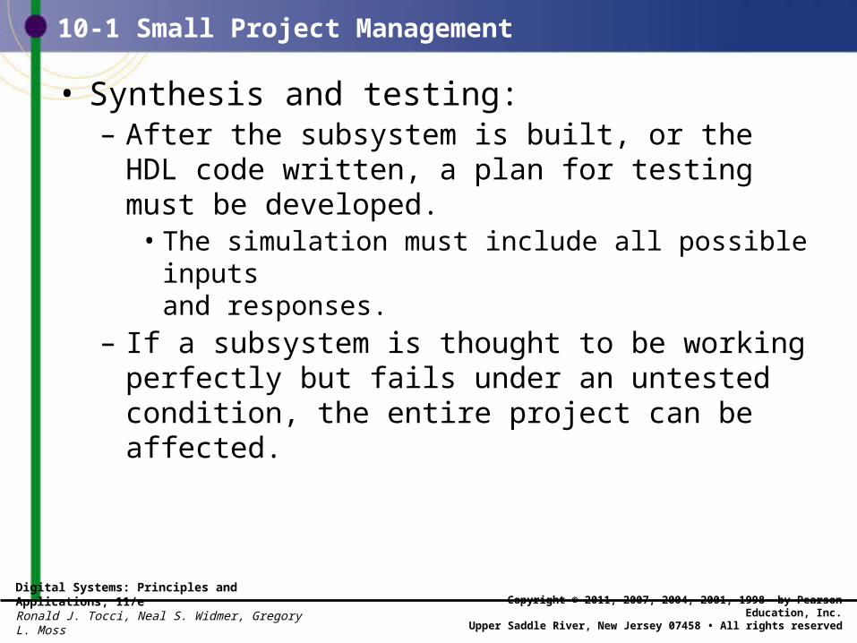
• Synthesis and testing:– After the subsystem is built, or the HDL code
written, a plan for testing must be developed.• The simulation must include all possible inputs
and responses.– If a subsystem is thought to be working perfectly
but fails under an untested condition, the entire project can be affected.

Digital Systems: Principles and Applications, 11/eRonald J. Tocci, Neal S. Widmer, Gregory L. Moss
Copyright © 2011, 2007, 2004, 2001, 1998 by Pearson Education, Inc.Upper Saddle River, New Jersey 07458 • All rights reserved
10-1 Small Project Management
• System integration and testing– Subsystems are assembled and tested as a unit.– This is the stage where unforeseen details surface.
• The importance of time cannot be overstated.– Most facets of the project will take 2-3 times longer
than thought.
Digital Systems: Principles and Applications, 11/eRonald J. Tocci, Neal S. Widmer, Gregory L. Moss
Copyright © 2011, 2007, 2004, 2001, 1998 by Pearson Education, Inc.Upper Saddle River, New Jersey 07458 • All rights reserved
10-2 A Stepper Motor Driver
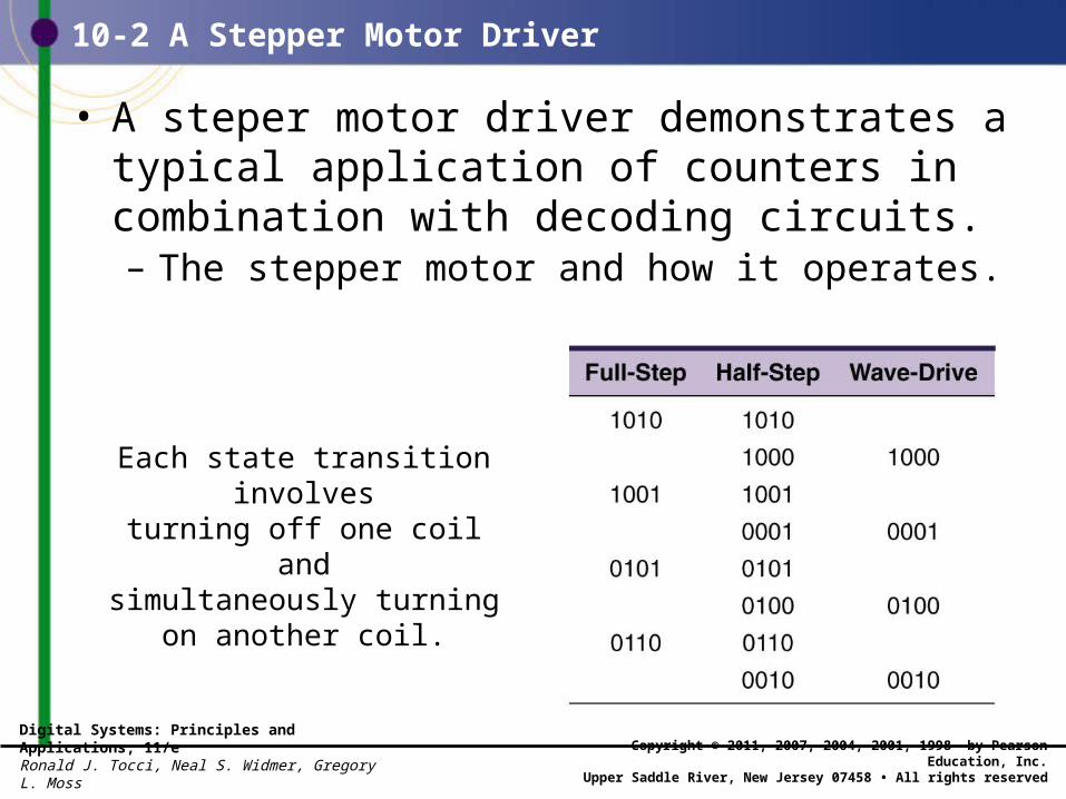
• A steper motor driver demonstrates a typical application of counters in combination with decoding circuits.– The stepper motor and how it operates.
Each state transition involvesturning off one coil andsimultaneously turning
on another coil.

Digital Systems: Principles and Applications, 11/eRonald J. Tocci, Neal S. Widmer, Gregory L. Moss
Copyright © 2011, 2007, 2004, 2001, 1998 by Pearson Education, Inc.Upper Saddle River, New Jersey 07458 • All rights reserved
10-2 A Stepper Motor Driver
A summary of stepper motor operating modes:
Digital Systems: Principles and Applications, 11/eRonald J. Tocci, Neal S. Widmer, Gregory L. Moss
Copyright © 2011, 2007, 2004, 2001, 1998 by Pearson Education, Inc.Upper Saddle River, New Jersey 07458 • All rights reserved
10-2 A Stepper Motor Driver
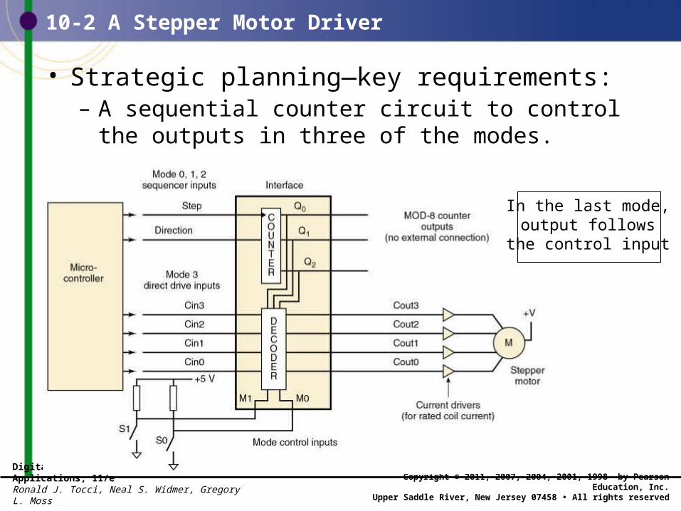
• Strategic planning—key requirements: – A sequential counter circuit to control the outputs
in three of the modes.
In the last mode, output follows the
control input

Digital Systems: Principles and Applications, 11/eRonald J. Tocci, Neal S. Widmer, Gregory L. Moss
Copyright © 2011, 2007, 2004, 2001, 1998 by Pearson Education, Inc.Upper Saddle River, New Jersey 07458 • All rights reserved
10-2 A Stepper Motor Driver
• Strategic planning—steps to completion:– Build an up/down counter.– Make each decoded sequence work with the counter.– Make the mode inputs select one decoder sequence
and add in the direct drive option.
Success will be realized when the circuit follows the states shown,in either direction, for each mode
sequence, and passes the four cin signals directly to cout in mode 3.
Digital Systems: Principles and Applications, 11/eRonald J. Tocci, Neal S. Widmer, Gregory L. Moss
Copyright © 2011, 2007, 2004, 2001, 1998 by Pearson Education, Inc.Upper Saddle River, New Jersey 07458 • All rights reserved
10-2 A Stepper Motor Driver
• Synthesis and testing– Verify the counter counts up, and down through
the 8 states.– Add one of the decoded outputs and test.– Additional count sequences are variations of
code already tested.

Digital Systems: Principles and Applications, 11/eRonald J. Tocci, Neal S. Widmer, Gregory L. Moss
Copyright © 2011, 2007, 2004, 2001, 1998 by Pearson Education, Inc.Upper Saddle River, New Jersey 07458 • All rights reserved
10-2 A Stepper Motor Driver
Synthesis and testing

Digital Systems: Principles and Applications, 11/eRonald J. Tocci, Neal S. Widmer, Gregory L. Moss
Copyright © 2011, 2007, 2004, 2001, 1998 by Pearson Education, Inc.Upper Saddle River, New Jersey 07458 • All rights reserved
10-2 A Stepper Motor Driver
The circuit is working.

Digital Systems: Principles and Applications, 11/eRonald J. Tocci, Neal S. Widmer, Gregory L. Moss
Copyright © 2011, 2007, 2004, 2001, 1998 by Pearson Education, Inc.Upper Saddle River, New Jersey 07458 • All rights reserved
10-3 A Keypad Encoder
Encode a 16 key keypad to 4-bit binary output.
10-3 A Keypad Encoder
Because keypads are often interfaced to a
computer bus system, encoded outputs shouldhave tristate enables.
Digital Systems: Principles and Applications, 11/eRonald J. Tocci, Neal S. Widmer, Gregory L. Moss
Copyright © 2011, 2007, 2004, 2001, 1998 by Pearson Education, Inc.Upper Saddle River, New Jersey 07458 • All rights reserved
10-3 A Keypad Encoder
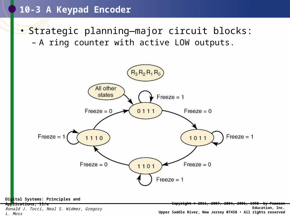
• Strategic planning—major circuit blocks:– A ring counter with active LOW outputs.

Digital Systems: Principles and Applications, 11/eRonald J. Tocci, Neal S. Widmer, Gregory L. Moss
Copyright © 2011, 2007, 2004, 2001, 1998 by Pearson Education, Inc.Upper Saddle River, New Jersey 07458 • All rights reserved
10-3 A Keypad Encoder
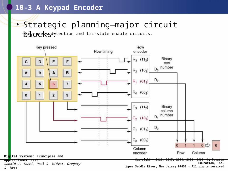
– Two encoders for the row and column numbers.
• Strategic planning—major circuit blocks:
Each state of this counter must be encodedto generate a two-bit binary row number.
Each column value must be encoded togenerate a two-bit binary column number.
Digital Systems: Principles and Applications, 11/eRonald J. Tocci, Neal S. Widmer, Gregory L. Moss
Copyright © 2011, 2007, 2004, 2001, 1998 by Pearson Education, Inc.Upper Saddle River, New Jersey 07458 • All rights reserved
10-3 A Keypad Encoder
– Key press detection and tri-state enable circuits.
• Strategic planning—major circuit blocks:
Digital Systems: Principles and Applications, 11/eRonald J. Tocci, Neal S. Widmer, Gregory L. Moss
Copyright © 2011, 2007, 2004, 2001, 1998 by Pearson Education, Inc.Upper Saddle River, New Jersey 07458 • All rights reserved
10-3 A Keypad Encoder
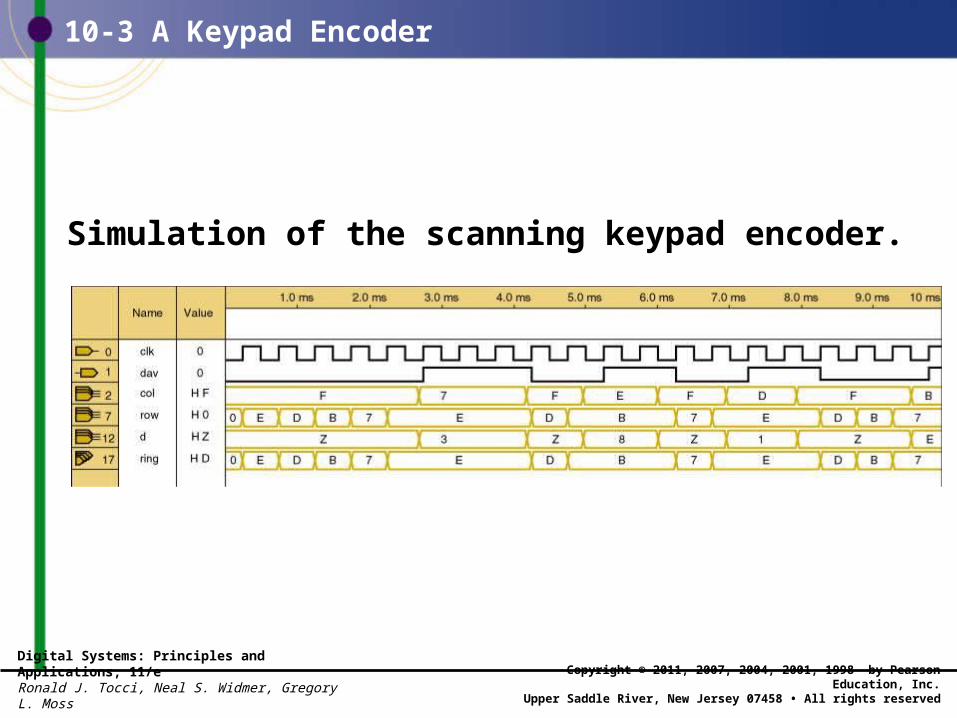
Simulation of the scanning keypad encoder.

Digital Systems: Principles and Applications, 11/eRonald J. Tocci, Neal S. Widmer, Gregory L. Moss
Copyright © 2011, 2007, 2004, 2001, 1998 by Pearson Education, Inc.Upper Saddle River, New Jersey 07458 • All rights reserved
10-4 Digital Clock Project
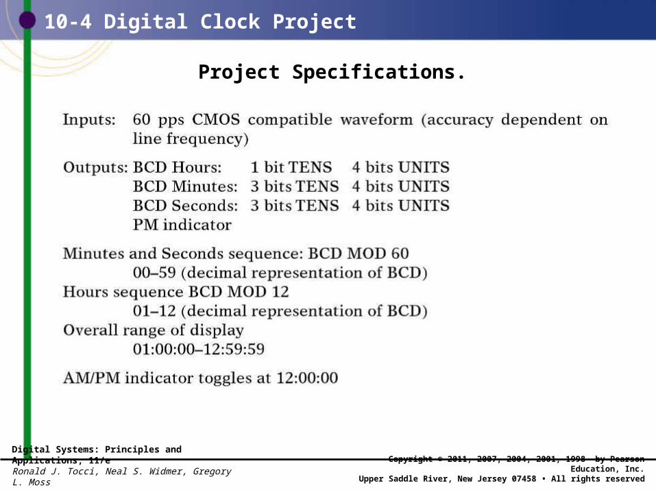
• A digital clock is a common counter application.– Display is given in hour, minutes, seconds.– A precise frequency is required.
• Battery operated devices use a crystal oscillator.• 60 Hz ac power line frequency is also used.
Digital Systems: Principles and Applications, 11/eRonald J. Tocci, Neal S. Widmer, Gregory L. Moss
Copyright © 2011, 2007, 2004, 2001, 1998 by Pearson Education, Inc.Upper Saddle River, New Jersey 07458 • All rights reserved
10-4 Digital Clock Project
Project Specifications.
Digital Systems: Principles and Applications, 11/eRonald J. Tocci, Neal S. Widmer, Gregory L. Moss
Copyright © 2011, 2007, 2004, 2001, 1998 by Pearson Education, Inc.Upper Saddle River, New Jersey 07458 • All rights reserved
10-4 Digital Clock Project
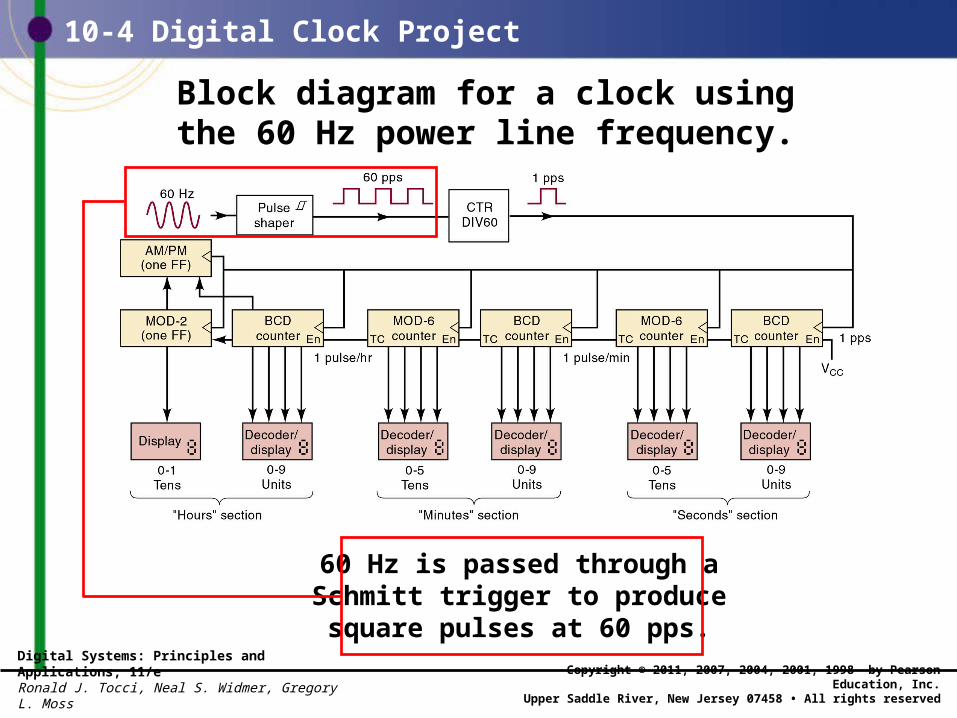
Block diagram for a clock usingthe 60 Hz power line frequency.
60 Hz is passed through a Schmitt trigger to produce square pulses at 60 pps.

Digital Systems: Principles and Applications, 11/eRonald J. Tocci, Neal S. Widmer, Gregory L. Moss
Copyright © 2011, 2007, 2004, 2001, 1998 by Pearson Education, Inc.Upper Saddle River, New Jersey 07458 • All rights reserved
10-4 Digital Clock Project
Block diagram for a clock usingthe 60 Hz power line frequency.
A MOD 60 counterdivides 60 to 1 pps.
Digital Systems: Principles and Applications, 11/eRonald J. Tocci, Neal S. Widmer, Gregory L. Moss
Copyright © 2011, 2007, 2004, 2001, 1998 by Pearson Education, Inc.Upper Saddle River, New Jersey 07458 • All rights reserved
10-4 Digital Clock Project
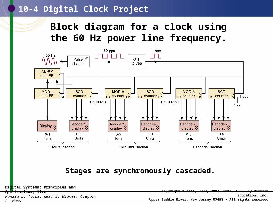
Block diagram for a clock usingthe 60 Hz power line frequency.
Stages are synchronously cascaded.

Digital Systems: Principles and Applications, 11/eRonald J. Tocci, Neal S. Widmer, Gregory L. Moss
Copyright © 2011, 2007, 2004, 2001, 1998 by Pearson Education, Inc.Upper Saddle River, New Jersey 07458 • All rights reserved
10-4 Digital Clock Project
Detail of HOURS section circuit.

Digital Systems: Principles and Applications, 11/eRonald J. Tocci, Neal S. Widmer, Gregory L. Moss
Copyright © 2011, 2007, 2004, 2001, 1998 by Pearson Education, Inc.Upper Saddle River, New Jersey 07458 • All rights reserved
10-4 Digital Clock Project
• Large, complex problems go through multiple levels of problem decomposition. – Referred to as a hierarchy.
• At each level, the interconnections between blocks should be as simple as possible.– With clear vision of function, a testing plan, and a
watch for common elements that can be reused.

Digital Systems: Principles and Applications, 11/eRonald J. Tocci, Neal S. Widmer, Gregory L. Moss
Copyright © 2011, 2007, 2004, 2001, 1998 by Pearson Education, Inc.Upper Saddle River, New Jersey 07458 • All rights reserved
10-4 Digital Clock Project
The top level block of the hierarchy.
The four subsections in the second level
of the hierarchy.

Digital Systems: Principles and Applications, 11/eRonald J. Tocci, Neal S. Widmer, Gregory L. Moss
Copyright © 2011, 2007, 2004, 2001, 1998 by Pearson Education, Inc.Upper Saddle River, New Jersey 07458 • All rights reserved
10-4 Digital Clock Project
The complete hierarchy of the clock project.
Simulation of the MOD-6 counter.

Digital Systems: Principles and Applications, 11/eRonald J. Tocci, Neal S. Widmer, Gregory L. Moss
Copyright © 2011, 2007, 2004, 2001, 1998 by Pearson Education, Inc.Upper Saddle River, New Jersey 07458 • All rights reserved
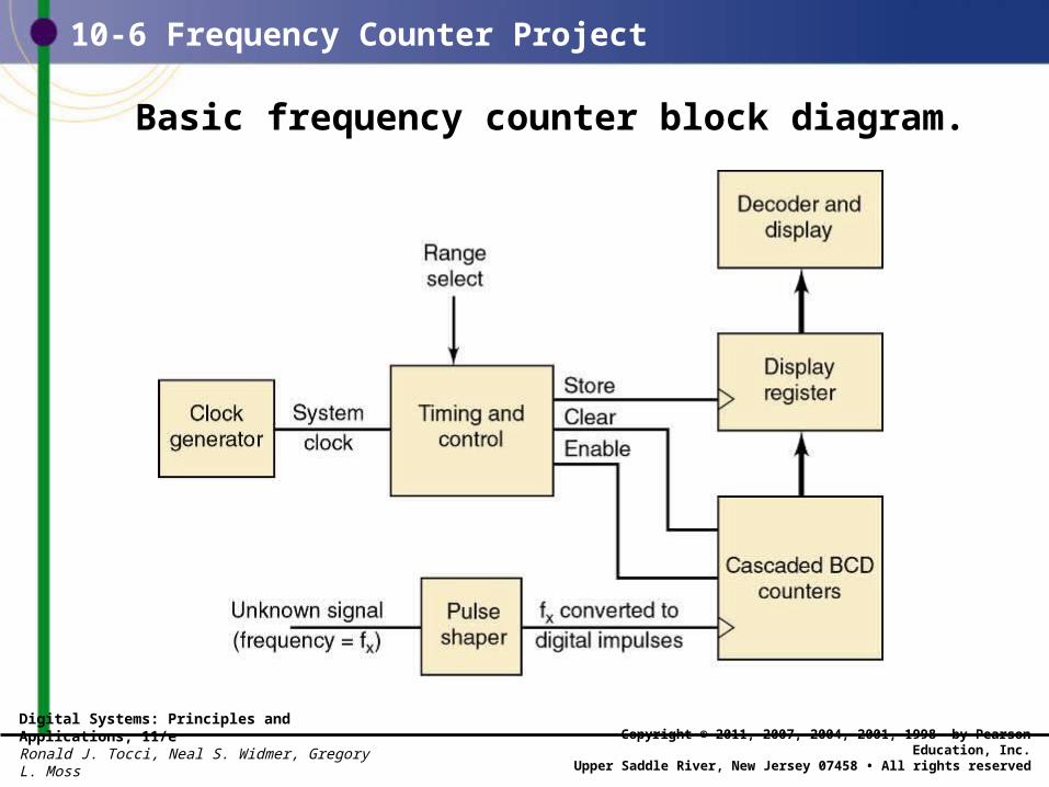
10-6 Frequency Counter Project
• A frequency counter is a circuit that canmeasure & display the frequency of a signal.– The frequency of a periodic waveform is the
number of cycles per second.
• Shaping each cycle of the frequency into a digital pulse allows a digital circuit to count the cycles.– Enabling a count of cycles (pulses) of the incoming
waveform during a precisely specified period of time.• The sampling interval.
Digital Systems: Principles and Applications, 11/eRonald J. Tocci, Neal S. Widmer, Gregory L. Moss
Copyright © 2011, 2007, 2004, 2001, 1998 by Pearson Education, Inc.Upper Saddle River, New Jersey 07458 • All rights reserved
10-6 Frequency Counter Project
• Length of the sampling interval determines the range of frequencies that can be measured.– A longer interval provides improved precision for low
frequencies—but will overflow at high frequencies. – A shorter interval provides less precise measurement
of low frequencies.• But can measure a much higher maximum frequency
without exceeding the upper limit of the counter.
Digital Systems: Principles and Applications, 11/eRonald J. Tocci, Neal S. Widmer, Gregory L. Moss
Copyright © 2011, 2007, 2004, 2001, 1998 by Pearson Education, Inc.Upper Saddle River, New Jersey 07458 • All rights reserved
10-6 Frequency Counter Project
Basic frequency counter block diagram.

Digital Systems: Principles and Applications, 11/eRonald J. Tocci, Neal S. Widmer, Gregory L. Moss
Copyright © 2011, 2007, 2004, 2001, 1998 by Pearson Education, Inc.Upper Saddle River, New Jersey 07458 • All rights reserved
10-6 Frequency Counter Project
Frequency counter timing diagram.

Digital Systems: Principles and Applications, 11/eRonald J. Tocci, Neal S. Widmer, Gregory L. Moss
Copyright © 2011, 2007, 2004, 2001, 1998 by Pearson Education, Inc.Upper Saddle River, New Jersey 07458 • All rights reserved
10-6 Frequency Counter Project
Timing and control block for frequency counter.
The timing and control block provides the “brains” for the frequency counter

END
Related Documents