PERSONAL COMMUNICATION PERSONAL COMMUNICATION SYSTEMS: 3G (IMT2000) SYSTEMS: 3G (IMT2000) Ian F. Akyildiz Ian F. Akyildiz Broadband & Wireless Networking Laboratory Broadband & Wireless Networking Laboratory School of Electrical and Computer Engineering School of Electrical and Computer Engineering Georgia Institute of Technology Georgia Institute of Technology Tel: 404-894-5141; Fax: 404-894-7883 Tel: 404-894-5141; Fax: 404-894-7883 Email: [email protected] Email: [email protected] Web: http://www.ece.gatech.edu/research/labs/bwn Web: http://www.ece.gatech.edu/research/labs/bwn

CHAPTER 10 (3G SYSTEMS
Aug 20, 2015
Welcome message from author
This document is posted to help you gain knowledge. Please leave a comment to let me know what you think about it! Share it to your friends and learn new things together.
Transcript
PERSONAL COMMUNICATION PERSONAL COMMUNICATION SYSTEMS: 3G (IMT2000)SYSTEMS: 3G (IMT2000)
Ian F. AkyildizIan F. Akyildiz
Broadband & Wireless Networking LaboratoryBroadband & Wireless Networking Laboratory
School of Electrical and Computer EngineeringSchool of Electrical and Computer Engineering
Georgia Institute of TechnologyGeorgia Institute of Technology
Tel: 404-894-5141; Fax: 404-894-7883 Tel: 404-894-5141; Fax: 404-894-7883
Email: [email protected]: [email protected]
Web: http://www.ece.gatech.edu/research/labs/bwnWeb: http://www.ece.gatech.edu/research/labs/bwn

2IFA’2004
IMT-2000IMT-2000 Higher data rates to support multimedia applications, Higher data rates to support multimedia applications,
high spectral efficiency, standardize as many high spectral efficiency, standardize as many interfaces as possible, and provide compatibility to interfaces as possible, and provide compatibility to services within the IMT-2000.services within the IMT-2000.
Requirements include: Requirements include: – Improved voice quality (wireline quality)Improved voice quality (wireline quality)– Data rates up to 384 kbps everywhere and 2 Mbps Data rates up to 384 kbps everywhere and 2 Mbps
indoorindoor– Support for packet and circuit switched data Support for packet and circuit switched data
servicesservices– Seamless incorporation of existing 2G and satellite Seamless incorporation of existing 2G and satellite
systemssystems– Seamless international roamingSeamless international roaming– Support for several simultaneous multimedia Support for several simultaneous multimedia
connectionsconnections
3IFA’2004
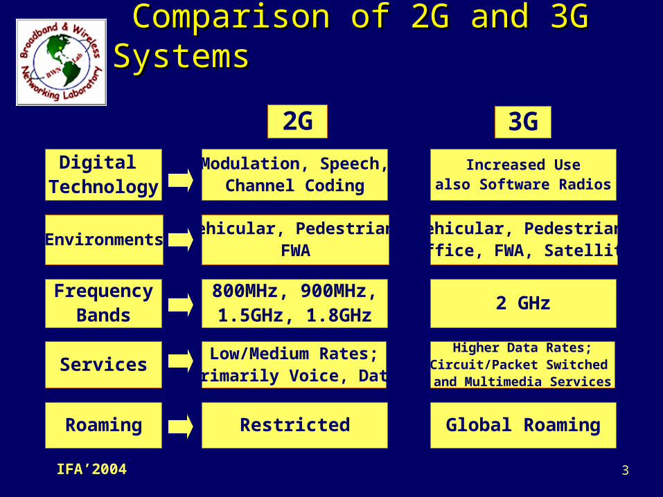
Comparison of 2G and 3G Comparison of 2G and 3G SystemsSystems
Digital Technology
Environments
FrequencyBands
Services
Roaming
Modulation, Speech,Channel Coding
Vehicular, Pedestrian,FWA
800MHz, 900MHz,1.5GHz, 1.8GHz
Low/Medium Rates;Primarily Voice, Data
Restricted
Increased Usealso Software Radios
Vehicular, Pedestrian,Office, FWA, Satellite
2 GHz
Higher Data Rates;Circuit/Packet Switched and Multimedia Services
Global Roaming
2G 3G

4IFA’2004
3G Wireless Systems3G Wireless Systems
IMT DS (Direct Sequence)IMT DS (Direct Sequence)
(UTRAN FDD and W-CDMA)(UTRAN FDD and W-CDMA) IMT MC (Multi-carrier)IMT MC (Multi-carrier)
– 3G version of IS-95 (called cdmaOne) 3G version of IS-95 (called cdmaOne) cdma2000cdma2000
IMT TC (Time Code)IMT TC (Time Code)– (UTRAN TDD)(UTRAN TDD)
IMT SC (Single Carrier)IMT SC (Single Carrier)– Essentially a manifestation of GSM Phase2+Essentially a manifestation of GSM Phase2+ ( EDGE)( EDGE)
Sixteen proposals are accepted to IMT-2000 systems family. Ten for terrestrial 3G networks, and six for MSSs (Mobile Satellite services)
5IFA’2004
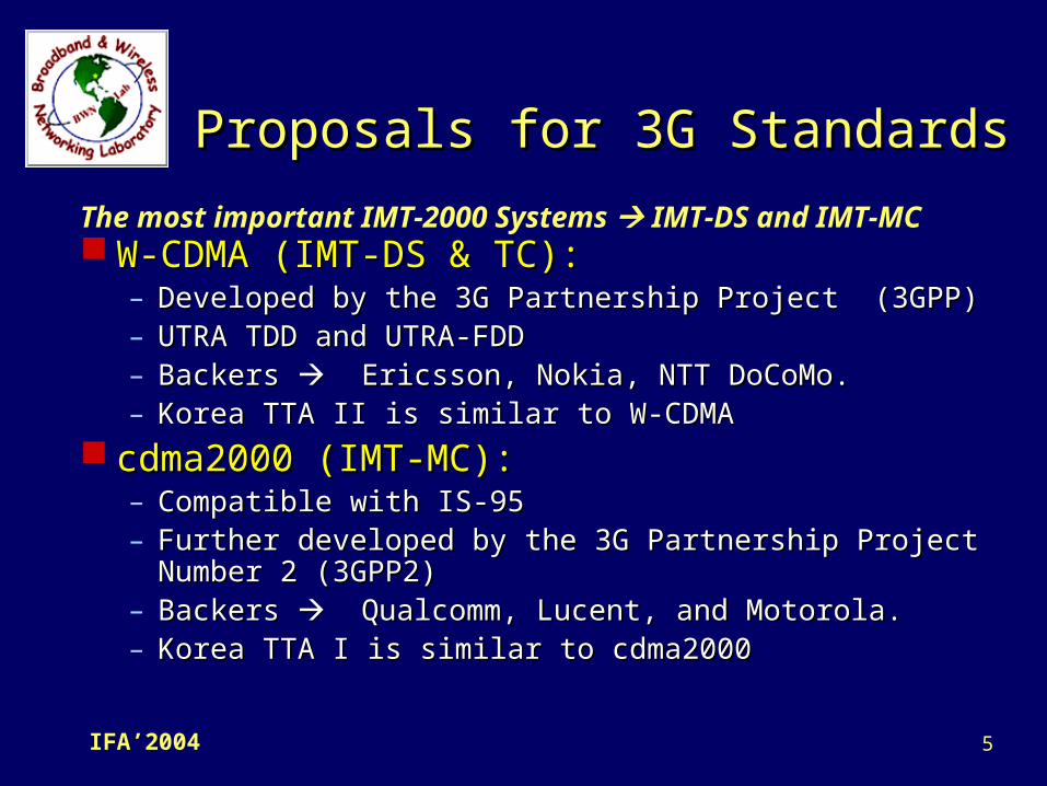
Proposals for 3G StandardsProposals for 3G Standards
W-CDMA (IMT-DS & TC):W-CDMA (IMT-DS & TC):– Developed by the 3G Partnership Project (3GPP)Developed by the 3G Partnership Project (3GPP)– UTRA TDD and UTRA-FDDUTRA TDD and UTRA-FDD– Backers Backers Ericsson, Nokia, NTT DoCoMo. Ericsson, Nokia, NTT DoCoMo.– Korea TTA II is similar to W-CDMAKorea TTA II is similar to W-CDMA
cdma2000 (IMT-MC): cdma2000 (IMT-MC): – Compatible with IS-95Compatible with IS-95– Further developed by the 3G Partnership Project Further developed by the 3G Partnership Project
Number 2 (3GPP2)Number 2 (3GPP2)– Backers Backers Qualcomm, Lucent, and Motorola. Qualcomm, Lucent, and Motorola.– Korea TTA I is similar to cdma2000 Korea TTA I is similar to cdma2000
The most important IMT-2000 Systems IMT-DS and IMT-MC

6IFA’2004
HierarchicalHierarchicalCell StructureCell Structure
Global RoamingGlobal RoamingRadio Radio
SpectrumSpectrum
3G ARCHITECTURE3G ARCHITECTURE

7IFA’2004
Key Features & Objectives of 3GKey Features & Objectives of 3G
Global System (all existing systems & Global System (all existing systems & terminal types)terminal types)
Worldwide market place & Off-the-shelf Worldwide market place & Off-the-shelf compatible equipmentcompatible equipment
Worldwide common frequency band & Worldwide common frequency band & roamingroaming
Audio, video and data services including Audio, video and data services including packet Data & multimedia Services packet Data & multimedia Services
High service qualityHigh service quality Flexible radio bearersFlexible radio bearers
8IFA’2004
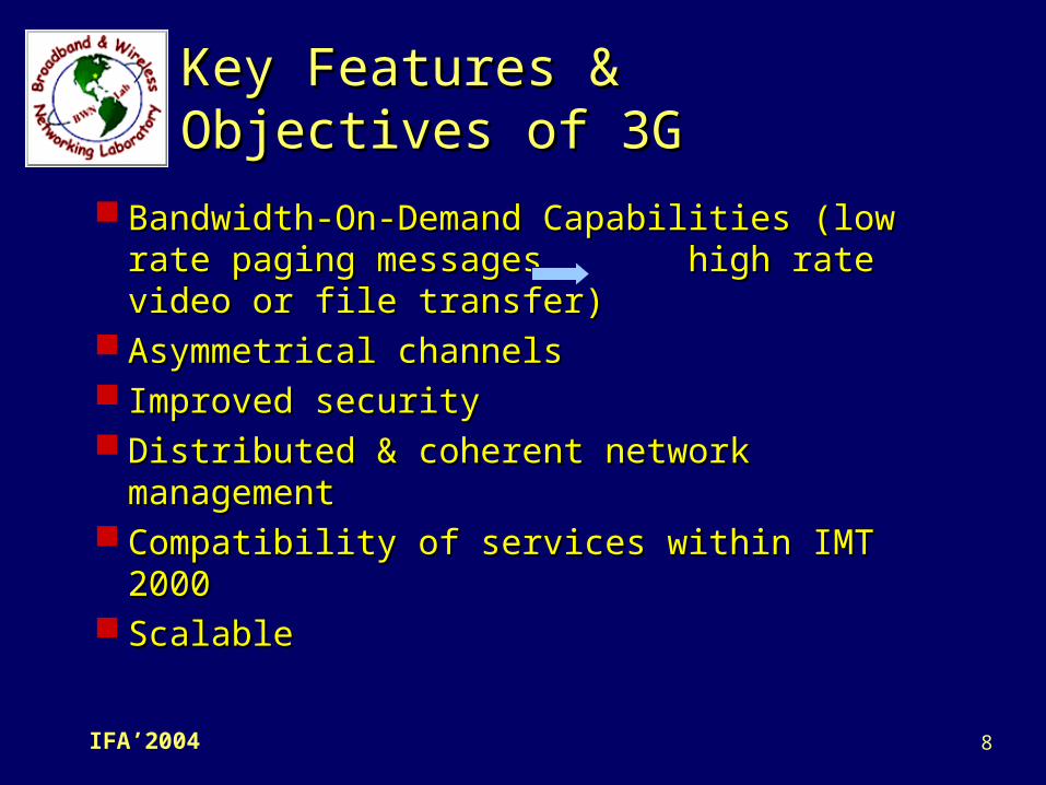
Key Features & Objectives Key Features & Objectives of 3Gof 3G
Bandwidth-On-Demand Capabilities (low Bandwidth-On-Demand Capabilities (low rate paging messages high rate video rate paging messages high rate video or file transfer)or file transfer)
Asymmetrical channelsAsymmetrical channels Improved securityImproved security Distributed & coherent network Distributed & coherent network
managementmanagement Compatibility of services within IMT 2000Compatibility of services within IMT 2000 ScalableScalable
9IFA’2004
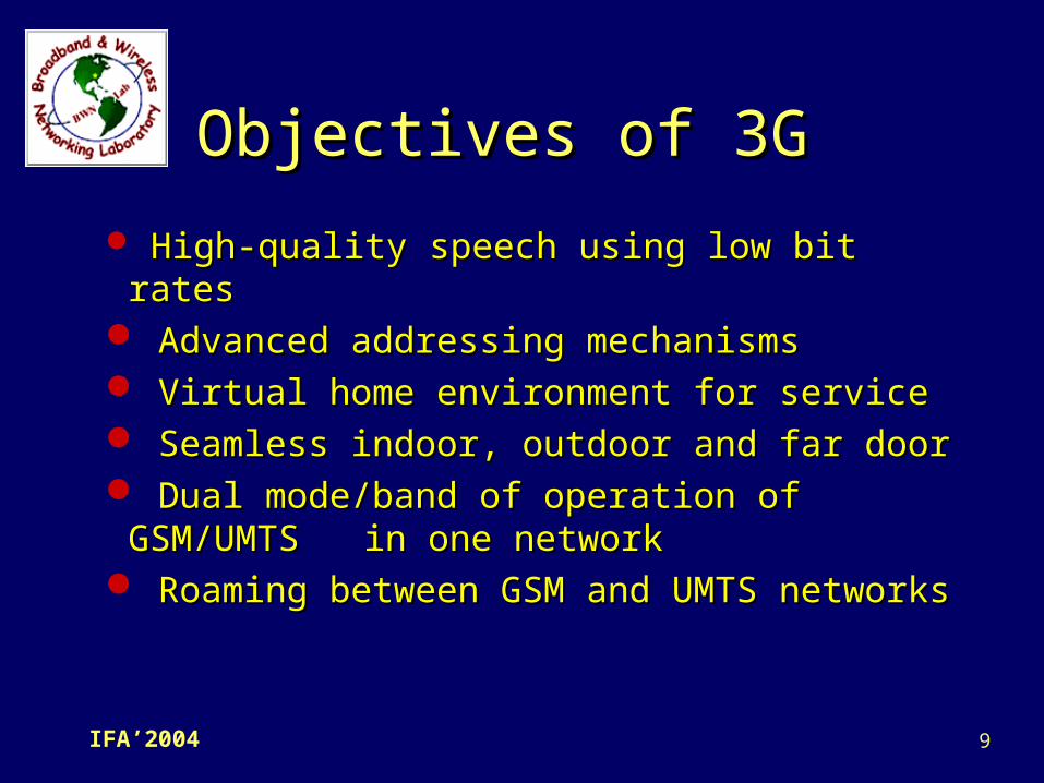
Objectives of 3GObjectives of 3G
High-quality speech using low bit ratesHigh-quality speech using low bit rates Advanced addressing mechanismsAdvanced addressing mechanisms Virtual home environment for serviceVirtual home environment for service Seamless indoor, outdoor and far doorSeamless indoor, outdoor and far door Dual mode/band of operation of Dual mode/band of operation of
GSM/UMTS in one networkGSM/UMTS in one network Roaming between GSM and UMTS Roaming between GSM and UMTS
networksnetworks

10IFA’2004
UMTSUMTS UMTS (Universal Mobile Telecommunications UMTS (Universal Mobile Telecommunications
System) is the European version of a 3System) is the European version of a 3rdrd Generation (3G) mobile communication Generation (3G) mobile communication system.system.– It is proposed by 3GPP (3It is proposed by 3GPP (3rdrd generation partnership generation partnership
project).project).– It includes two parts: UTRAN (Universal Terrestrial It includes two parts: UTRAN (Universal Terrestrial
Radio Access Network) and the Core network Radio Access Network) and the Core network inherited from GSM (Global System for Mobile inherited from GSM (Global System for Mobile Communications).Communications).
UMTS is a wideband, circuit- and packet-UMTS is a wideband, circuit- and packet-based transmission systems of text, based transmission systems of text, digitized voice, video, and multimedia with digitized voice, video, and multimedia with data rates up to 2 Mbps (possibly higher). data rates up to 2 Mbps (possibly higher).
11IFA’2004
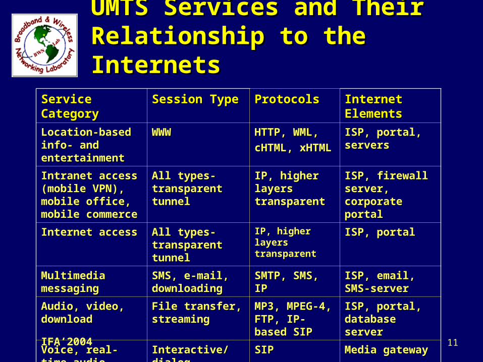
UMTS Services and UMTS Services and Their Relationship to Their Relationship to the Internetsthe Internets
Service Service CategoryCategory
Session TypeSession Type ProtocolsProtocols Internet Internet ElementsElements
Location-based Location-based info- and info- and entertainmententertainment
WWWWWW HTTP, WML,HTTP, WML,
cHTML, cHTML, xHTMLxHTML
ISP, portal, ISP, portal, serversservers
Intranet access Intranet access (mobile VPN), (mobile VPN), mobile office, mobile office, mobile mobile commercecommerce
All types-All types-transparent transparent tunneltunnel
IP, higher IP, higher layers layers transparenttransparent
ISP, firewall ISP, firewall server, server, corporate corporate portalportal
Internet accessInternet access All types-All types-transparent transparent tunneltunnel
IP, higher IP, higher layers layers transparenttransparent
ISP, portalISP, portal
Multimedia Multimedia messagingmessaging
SMS, e-mail, SMS, e-mail, downloadingdownloading
SMTP, SMS, SMTP, SMS, IPIP
ISP, email, ISP, email, SMS-serverSMS-server
Audio, video, Audio, video, downloaddownload
File transfer, File transfer, streamingstreaming
MP3, MPEG-MP3, MPEG-4, FTP, IP-4, FTP, IP-based SIPbased SIP
ISP, portal, ISP, portal, database database serverserver
Voice, real-time Voice, real-time audio, videoaudio, video
Interactive/Interactive/dialog dialog streaming/one-streaming/one-wayway
SIPSIP Media gatewayMedia gateway
12IFA’2004
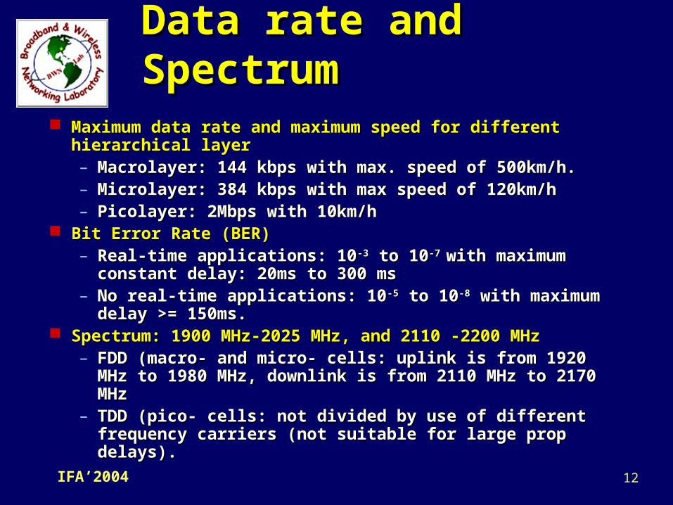
Data rate and Data rate and SpectrumSpectrum
Maximum data rate and maximum speed for different Maximum data rate and maximum speed for different hierarchical layerhierarchical layer– Macrolayer: 144 kbps with max. speed of 500km/h.Macrolayer: 144 kbps with max. speed of 500km/h.– Microlayer: 384 kbps with max speed of 120km/hMicrolayer: 384 kbps with max speed of 120km/h– Picolayer: 2Mbps with 10km/hPicolayer: 2Mbps with 10km/h
Bit Error Rate (BER)Bit Error Rate (BER)– Real-time applications: 10Real-time applications: 10-3-3 to 10 to 10-7 -7 with maximum with maximum
constant delay: 20ms to 300 msconstant delay: 20ms to 300 ms– No real-time applications: 10No real-time applications: 10-5-5 to 10 to 10-8-8 with maximum with maximum
delay >= 150ms.delay >= 150ms. Spectrum: 1900 MHz-2025 MHz, and 2110 -2200 MHzSpectrum: 1900 MHz-2025 MHz, and 2110 -2200 MHz
– FDD (macro- and micro- cells: uplink is from 1920 FDD (macro- and micro- cells: uplink is from 1920 MHz to 1980 MHz, downlink is from 2110 MHz to MHz to 1980 MHz, downlink is from 2110 MHz to 2170 MHz2170 MHz
– TDD (pico- cells: not divided by use of different TDD (pico- cells: not divided by use of different frequency carriers (not suitable for large prop frequency carriers (not suitable for large prop delays).delays).
13IFA’2004
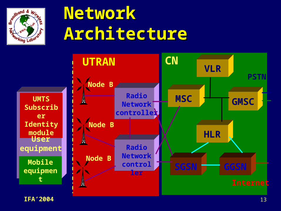
Network Network ArchitectureArchitecture
UMTSSubscriber
Identitymodule
Mobileequipment
Userequipment
RadioNetwork
controller
RadioNetwork
controller
Node B
Node B
Node B
VLR
GMSC
HLR
MSC
SGSN GGSN
Internet
PSTN
ISDN
UTRAN CN

14IFA’2004
Radio Network Controller Radio Network Controller (RNC)(RNC)
One RNC controls one or more Node Bs.One RNC controls one or more Node Bs. It may be connected via Iu interface to an It may be connected via Iu interface to an
MSC (IuCS), or to an SGSN via Iu (IuPS).MSC (IuCS), or to an SGSN via Iu (IuPS). The interface between RNCs (Iur) is The interface between RNCs (Iur) is
logical interface, and a direct physical logical interface, and a direct physical connection does not necessarily exist.connection does not necessarily exist.
An RNC is comparable to a base station An RNC is comparable to a base station controller (BSC) in GSM networks.controller (BSC) in GSM networks.
15IFA’2004
RNC FunctionsRNC Functions Iub (Node B and RNC) transport resources Iub (Node B and RNC) transport resources
managementmanagement Control of Node B logical O&M resourcesControl of Node B logical O&M resources System information management and schedulingSystem information management and scheduling Traffic management of common channelsTraffic management of common channels Soft handoverSoft handover Power control for uplink and downlinkPower control for uplink and downlink Admission controlAdmission control Traffic management of shared channelsTraffic management of shared channels Macro diversity combining/splitting of data Macro diversity combining/splitting of data
streams transferred over several Node Bs.streams transferred over several Node Bs.
16IFA’2004
Node BNode B
Node B is the UMTS equivalent of a base station Node B is the UMTS equivalent of a base station transceiver. It may support one or more cells, transceiver. It may support one or more cells, although in general only one cell one Node B.although in general only one cell one Node B.
It is a logical terminal and the base station is It is a logical terminal and the base station is often used for physical entity.often used for physical entity.
FunctionsFunctions– Mapping of Node B logical resources onto hardware Mapping of Node B logical resources onto hardware
resourcesresources– Uplink power controlUplink power control– Reporting of uplink interference measurements and Reporting of uplink interference measurements and
downlink power informationdownlink power information– Contains the air interface physical layer, it has to perform Contains the air interface physical layer, it has to perform
many functions such as RF processing, modulations, many functions such as RF processing, modulations, coding, and so on.coding, and so on.
17IFA’2004
WCDMA Air WCDMA Air InterfaceInterface
In UMTS, the UTRAN is used to keep the mobility In UMTS, the UTRAN is used to keep the mobility management (MM) and connection management management (MM) and connection management (CM) layers independent of the air interface radio (CM) layers independent of the air interface radio technologytechnology
This idea is realized as the concepts of access This idea is realized as the concepts of access stratum (AS) and nonaccess stratum (NAS)stratum (AS) and nonaccess stratum (NAS)– AS: functional entity that includes radio access AS: functional entity that includes radio access
protocols between the user equipment (UE) and protocols between the user equipment (UE) and the UTRAN (terminate here).the UTRAN (terminate here).
– NAS: includes core network (CN) protocols NAS: includes core network (CN) protocols between the UE and the CN itself.between the UE and the CN itself.
The NAS protocols can be kept the same, thus, the The NAS protocols can be kept the same, thus, the GSM’s MM and CM resources are used almost GSM’s MM and CM resources are used almost unchanged in 3G NAS.unchanged in 3G NAS.
18IFA’2004
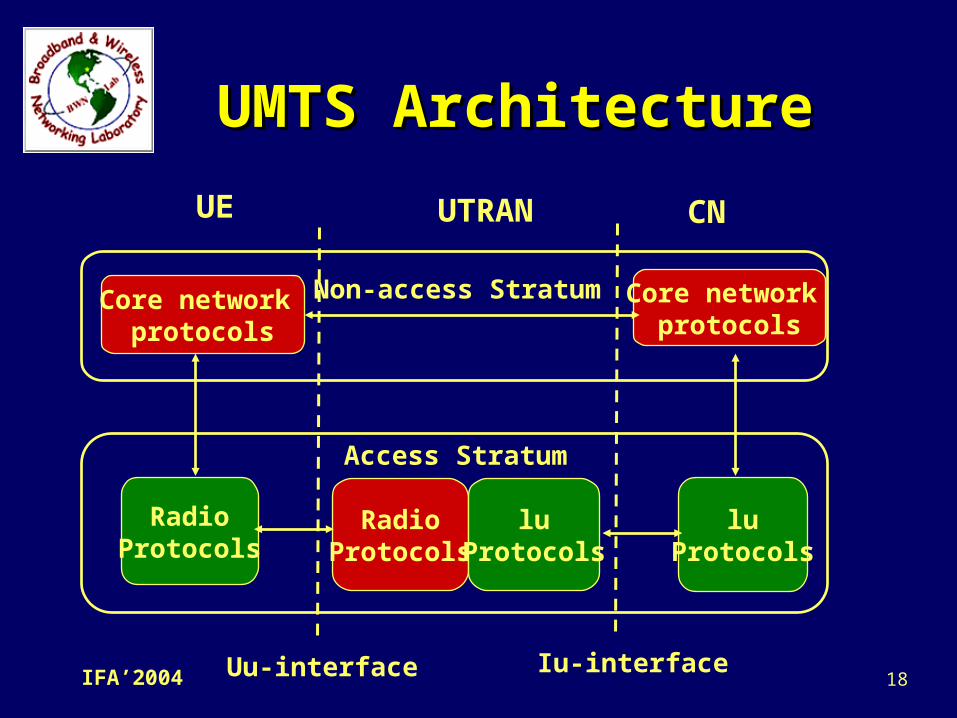
UMTS ArchitectureUMTS Architecture
Core network protocols
Core network protocols
Non-access Stratum
RadioProtocols
RadioProtocols
luProtocols
luProtocols
Access Stratum
Uu-interface Iu-interface
UE UTRAN CN
19IFA’2004
Layered Layered ArchitectureArchitecture
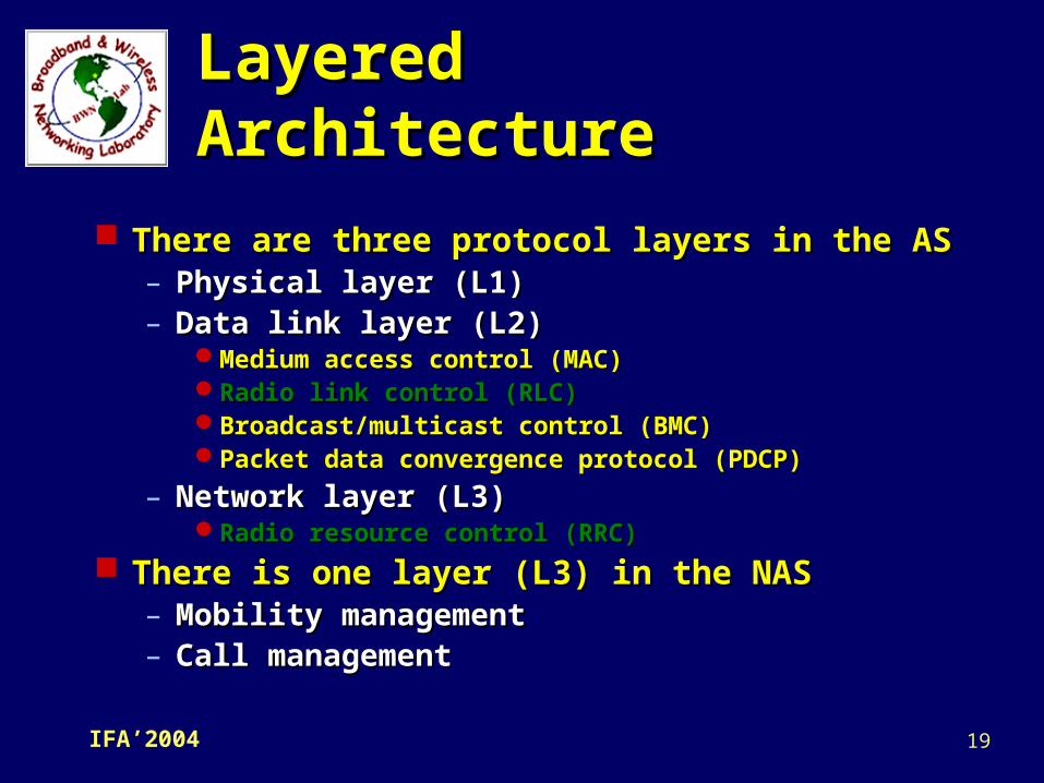
There are three protocol layers in the ASThere are three protocol layers in the AS– Physical layer (L1)Physical layer (L1)– Data link layer (L2)Data link layer (L2)
Medium access control (MAC)Medium access control (MAC)Radio link control (RLC)Radio link control (RLC)Broadcast/multicast control (BMC)Broadcast/multicast control (BMC)Packet data convergence protocol (PDCP)Packet data convergence protocol (PDCP)
– Network layer (L3)Network layer (L3)Radio resource control (RRC)Radio resource control (RRC)
There is one layer (L3) in the NASThere is one layer (L3) in the NAS– Mobility managementMobility management– Call managementCall management

20IFA’2004
RLC ServicesRLC Services
Segmentation and reassembly of Segmentation and reassembly of higher-layer PDUs (Protocol Data Unit) higher-layer PDUs (Protocol Data Unit) into/from smaller RLC payload unitsinto/from smaller RLC payload units
PaddingPadding Transfer of user dataTransfer of user data Error correctionsError corrections In-sequence delivery of higher-layer In-sequence delivery of higher-layer
PDUsPDUs CipheringCiphering Sequence number checkSequence number check
These functions are provided to upper layers:
21IFA’2004
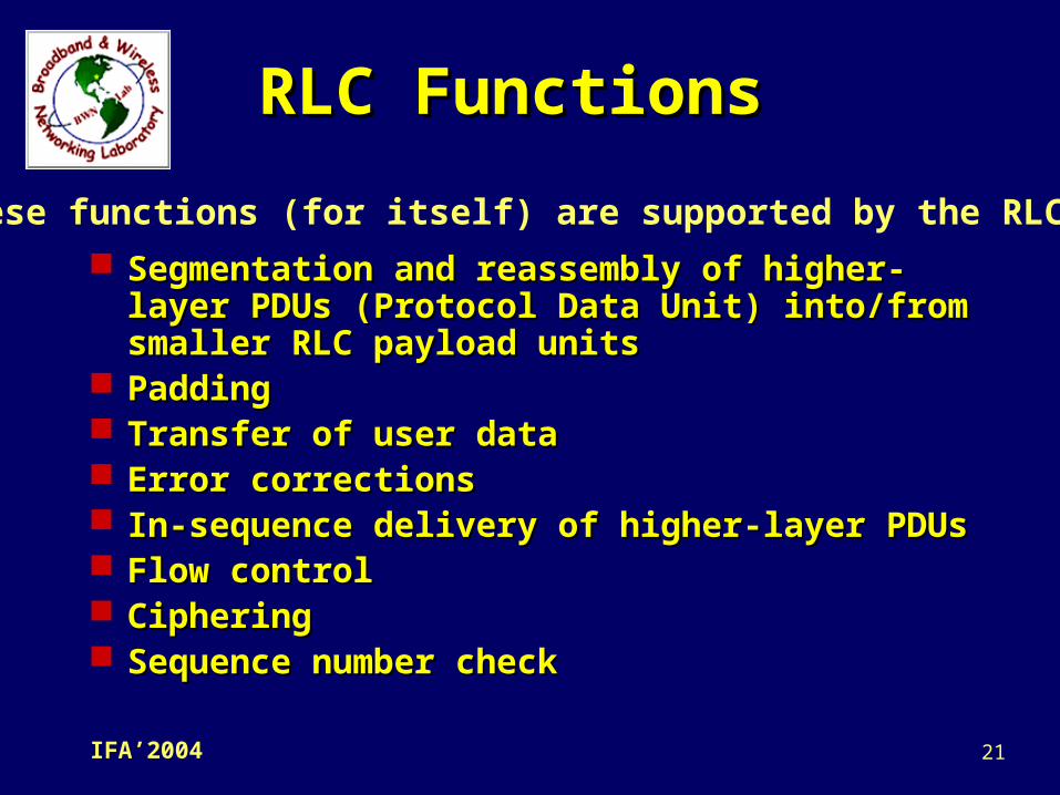
RLC FunctionsRLC Functions
Segmentation and reassembly of higher-Segmentation and reassembly of higher-layer PDUs (Protocol Data Unit) into/from layer PDUs (Protocol Data Unit) into/from smaller RLC payload unitssmaller RLC payload units
PaddingPadding Transfer of user dataTransfer of user data Error correctionsError corrections In-sequence delivery of higher-layer In-sequence delivery of higher-layer
PDUsPDUs Flow controlFlow control CipheringCiphering Sequence number checkSequence number check
These functions (for itself) are supported by the RLC:

22IFA’2004
RRC ServicesRRC Services
General control: this is an information broadcast General control: this is an information broadcast service. The information transferred in service. The information transferred in unacknowledged, and it is broadcast to all unacknowledged, and it is broadcast to all mobiles within a certain area.mobiles within a certain area.
Notification: This includes paging and notification Notification: This includes paging and notification broadcast services. broadcast services. – The paging services broadcasts paging The paging services broadcasts paging
information in a certain geographical area, but information in a certain geographical area, but it is addressed to a specific UE or UEs.it is addressed to a specific UE or UEs.
– The notification broadcast service is defined to The notification broadcast service is defined to provide information broadcast to all UEs in a provide information broadcast to all UEs in a cell or cells.cell or cells.
Dedicated control: This service includes the Dedicated control: This service includes the establishment and release of a connection and establishment and release of a connection and transfer of messages using this connection. transfer of messages using this connection.
23IFA’2004
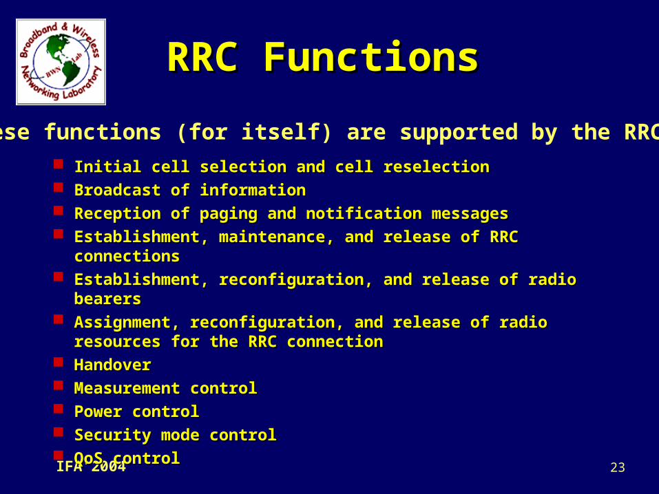
RRC FunctionsRRC Functions
Initial cell selection and cell reselectionInitial cell selection and cell reselection Broadcast of informationBroadcast of information Reception of paging and notification messagesReception of paging and notification messages Establishment, maintenance, and release of RRC Establishment, maintenance, and release of RRC
connectionsconnections Establishment, reconfiguration, and release of radio Establishment, reconfiguration, and release of radio
bearersbearers Assignment, reconfiguration, and release of radio Assignment, reconfiguration, and release of radio
resources for the RRC connectionresources for the RRC connection HandoverHandover Measurement controlMeasurement control Power controlPower control Security mode controlSecurity mode control QoS controlQoS control
These functions (for itself) are supported by the RRC:
24IFA’2004
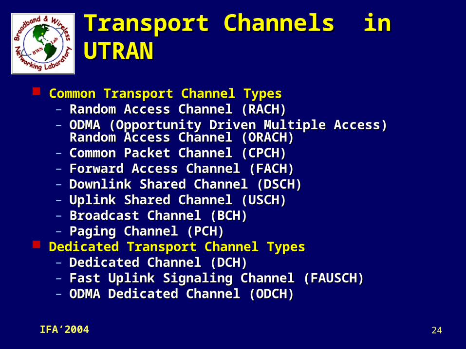
Common Transport Channel TypesCommon Transport Channel Types– Random Access Channel (RACH) Random Access Channel (RACH) – ODMA (Opportunity Driven Multiple Access)ODMA (Opportunity Driven Multiple Access)
Random Access Channel (ORACH)Random Access Channel (ORACH)– Common Packet Channel (CPCH) Common Packet Channel (CPCH) – Forward Access Channel (FACH)Forward Access Channel (FACH)– Downlink Shared Channel (DSCH) Downlink Shared Channel (DSCH) – Uplink Shared Channel (USCH) Uplink Shared Channel (USCH) – Broadcast Channel (BCH) Broadcast Channel (BCH) – Paging Channel (PCH) Paging Channel (PCH)
Dedicated Transport Channel TypesDedicated Transport Channel Types– Dedicated Channel (DCH) Dedicated Channel (DCH) – Fast Uplink Signaling Channel (FAUSCH) Fast Uplink Signaling Channel (FAUSCH) – ODMA Dedicated Channel (ODCH) ODMA Dedicated Channel (ODCH)
Transport Channels in Transport Channels in UTRANUTRAN

25IFA’2004
Broadcast Control Channel (BCCH) Paging Control Channel (PCCH) Dedicated Control Channel (DCCH)
Common Control Channel (CCCH)
Control Channel (CCH)
Dedicated Traffic Channel (DTCH)
Traffic Channel (TCH)
ODMA Dedicated Control Channel (ODCCH)
ODMA Common Control Channel (OCCCH)
ODMA Dedicated Traffic Channel (ODTCH)
Common Traffic Channel (CTCH)
Shared Channel Control Channel (SHCCH)
Logical Channels in Logical Channels in UTRANUTRAN
26IFA’2004
Quality of Services Quality of Services ClassesClasses
The UMTS allows the UEs to negotiate the QoS The UMTS allows the UEs to negotiate the QoS parameters for a radio bearer (RB).parameters for a radio bearer (RB).
NegotiationNegotiation– The procedure is always initiated by the The procedure is always initiated by the
application in the UE.application in the UE.– It sends a request defining the resources it It sends a request defining the resources it
needsneeds– The network checks whether it can provide the The network checks whether it can provide the
requested resources.requested resources.– It can either grant the requested resources, It can either grant the requested resources,
offer a small amount of resources, or reject the offer a small amount of resources, or reject the request.request.
– The UE can either accept or reject the modified The UE can either accept or reject the modified offer.offer.
– It is also possible to renegotiate these It is also possible to renegotiate these parameters if the application requirements parameters if the application requirements change or resource status change.change or resource status change.

27IFA’2004
QoS Classes (2)QoS Classes (2)
There are four types of QoS classesThere are four types of QoS classes
– Conversational real-time class such Conversational real-time class such as voice trafficas voice traffic
– Interactive class (best-effort) such Interactive class (best-effort) such as web browsingas web browsing
– Streaming real-time class such as Streaming real-time class such as streaming videostreaming video
– Background class (best-effort) such Background class (best-effort) such as emails.as emails.

28IFA’2004
Conversational Real-Time Conversational Real-Time ServicesServices
Bidirectional and more or less symmetricBidirectional and more or less symmetric Technically the most challenging classTechnically the most challenging class
– Very short delay is acceptableVery short delay is acceptable– Traditional retransmission protocols (ARQ) Traditional retransmission protocols (ARQ)
cannot be easily used. Instead, forward-cannot be easily used. Instead, forward-error-correction (FEC) must be used.error-correction (FEC) must be used.
– Small delay requirements means also that Small delay requirements means also that buffers cannot be used in receiving end to buffers cannot be used in receiving end to smooth the variations in delay (jitter).smooth the variations in delay (jitter).
Some errors are acceptable because people Some errors are acceptable because people cannot sense small errors in voice or video cannot sense small errors in voice or video information.information.
29IFA’2004
Interactive ServicesInteractive Services
A user requests data from a remote server, and the A user requests data from a remote server, and the response contains the requested data.response contains the requested data.– Web browsing, e-shopping, and database inquires.Web browsing, e-shopping, and database inquires.
Difference between conversational and interactive Difference between conversational and interactive servicesservices– The data traffic in the conversational class is The data traffic in the conversational class is
symmetric, whereas in the interactive class, the symmetric, whereas in the interactive class, the traffic is highly asymmetric.traffic is highly asymmetric.
– Timing requirements are not quite so strict with Timing requirements are not quite so strict with interactive services (up to 4 seconds) as they are interactive services (up to 4 seconds) as they are for conversational services (a few hundred of ms).for conversational services (a few hundred of ms).
– Interactive services do not tolerate any more Interactive services do not tolerate any more transmission errors than conversational services.transmission errors than conversational services.
With the relaxation of delay requirements, the goal With the relaxation of delay requirements, the goal of less errors is easier to achieve with interactive of less errors is easier to achieve with interactive services.services.
30IFA’2004
Streaming ServicesStreaming Services Typically includes video and audio applications.Typically includes video and audio applications. Differences from interactive services:Differences from interactive services:
– The data transferring is almost totally one-way and The data transferring is almost totally one-way and continuous: highly asymmetric.continuous: highly asymmetric.
– There are some strict delay variation requirements There are some strict delay variation requirements for the data, which are presented to the user, for the data, which are presented to the user, whereas delay variation is not really a problem with whereas delay variation is not really a problem with interactive services.interactive services.
– The requirements for maximum delay could be as The requirements for maximum delay could be as long as 10 seconds.long as 10 seconds.
– The only data traffic in the opposite direction The only data traffic in the opposite direction ( usually in the uplink) consists of a few control ( usually in the uplink) consists of a few control signals like starting and stopping.signals like starting and stopping.
– The incoming data packets are buffered to smooth The incoming data packets are buffered to smooth delay variation.delay variation.
This class is provided through packet-switched This class is provided through packet-switched networks.networks.
31IFA’2004
Background ServicesBackground Services
These services do not have precise delay requirements These services do not have precise delay requirements at all (fax and SMS).at all (fax and SMS).
However, it may use timers to make sure that the data However, it may use timers to make sure that the data transfer has not stalled altogether.transfer has not stalled altogether.
The data should be error free, but it is especially easy The data should be error free, but it is especially easy to achieve in this case. Because there are no time to achieve in this case. Because there are no time constraints.constraints.
Retransmission protocol will be used, but it must also Retransmission protocol will be used, but it must also be efficient.be efficient.
Delay variation is not considered with background Delay variation is not considered with background services. The data are presented to the user only after services. The data are presented to the user only after the whole file has been received correctly.the whole file has been received correctly.
The bandwidth requirement is not large in either The bandwidth requirement is not large in either direction.direction.
32IFA’2004
RRC Connection RRC Connection ProceduresProcedures
The UTRAN separates the concepts of a radio The UTRAN separates the concepts of a radio connectionconnection from from a radio a radio bearerbearer (RB). (RB).– A radio connection is created first, and then the network A radio connection is created first, and then the network
can create one or more RBs independently of the radio can create one or more RBs independently of the radio connection.connection.
– An RB can also exist without a dedicated radio connection. An RB can also exist without a dedicated radio connection. In this case, the RB uses the common channels.In this case, the RB uses the common channels.
An RRC connection implies that a radio connection exists, but An RRC connection implies that a radio connection exists, but this connection can use either dedicated or common this connection can use either dedicated or common resources.resources.– An RRC connection is a logical concept, and radio An RRC connection is a logical concept, and radio
connection is a physical concept.connection is a physical concept.– The physical entity implements and enables the logical The physical entity implements and enables the logical
concepts. concepts. – A dedicated connection allocates the resource exclusively A dedicated connection allocates the resource exclusively
to one user, so common channels should be used whenever to one user, so common channels should be used whenever possible.possible.

33IFA’2004
RRC RRC Establishment/ReleaseEstablishment/Release
RRC connection establishment RRC connection establishment – It is always initiated by the UE, even with a mobile-It is always initiated by the UE, even with a mobile-
terminated call (e.g.,paging).terminated call (e.g.,paging).– The UE initiates this procedure, but the UTRAN The UE initiates this procedure, but the UTRAN
controls it. It may decide that no radio resources can controls it. It may decide that no radio resources can be allocated for the UE, and respond with an RRC be allocated for the UE, and respond with an RRC connection rejectconnection reject message. message.
Signaling connection establishmentSignaling connection establishment– The RRC connection establishment procedure is used The RRC connection establishment procedure is used
by the higher layer; that is, by the NAS.by the higher layer; that is, by the NAS.– All higher-layer signaling messages, including the All higher-layer signaling messages, including the
initial messages are relayed through the radio initial messages are relayed through the radio interface.interface.
RRC connection releaseRRC connection release– The normal procedure is finished through a dedicated The normal procedure is finished through a dedicated
channel (DCH). The PDU here are sent in channel (DCH). The PDU here are sent in unacknowledged mode. unacknowledged mode.
34IFA’2004
Radio Bearer Radio Bearer ProceduresProcedures
Radio connection and an RB are two Radio connection and an RB are two separate concepts in UMTS.separate concepts in UMTS.– Radio connection is a static concept. It is Radio connection is a static concept. It is
established once, and survives until it is established once, and survives until it is released. There is only one radio connection released. There is only one radio connection per terminal.per terminal.
– The RB defines what kind of properties this The RB defines what kind of properties this radio connection has. There may be several radio connection has. There may be several RBs on one radio connection, each having RBs on one radio connection, each having different capabilities for data transfer. The different capabilities for data transfer. The capabilities are based on the QoS parameters.capabilities are based on the QoS parameters.
– The RBs are dynamic and can be reconfigured.The RBs are dynamic and can be reconfigured.

35IFA’2004
Radio Bearer Radio Bearer Procedures (2)Procedures (2)
– It is possible to have an RB without It is possible to have an RB without a dedicated radio connectiona dedicated radio connectionCircuit-switched bearers or bearers using Circuit-switched bearers or bearers using
rt services need dedicated radio channels rt services need dedicated radio channels to meet their strict delay requirements.to meet their strict delay requirements.
Packet-switched bearers or bearers using Packet-switched bearers or bearers using nrt services, often do not need a nrt services, often do not need a permanent association to a dedicated permanent association to a dedicated radio resource.radio resource.
36IFA’2004
Radio Bearer Radio Bearer establishment Radio establishment Radio Bearer releaseBearer release
An RB establishment is always initiated by the An RB establishment is always initiated by the UTRAN. This because each RB uses some radio UTRAN. This because each RB uses some radio resources, and only the network knows what kind of resources, and only the network knows what kind of resources it can grant to a UE.resources it can grant to a UE.
At the RRC level, the signaling is simple: the UTRAN At the RRC level, the signaling is simple: the UTRAN sends a sends a radio bearer setupradio bearer setup message, and the UE message, and the UE responds with a responds with a radio bearer setup completeradio bearer setup complete..
Interlayer signaling can be quite different depending Interlayer signaling can be quite different depending on the requested QoS parameter and whether there on the requested QoS parameter and whether there is already a suitable physical channel in place.is already a suitable physical channel in place.
When an RB is released, the physical channel can be When an RB is released, the physical channel can be modified or released together depending on whether modified or released together depending on whether it can be “reused” after the RB release.it can be “reused” after the RB release.
37IFA’2004
Control of Requested Control of Requested QoSQoS
The UTRAN air interface is very flexible, The UTRAN air interface is very flexible, which allows for the dynamic allocation of which allows for the dynamic allocation of system resources.system resources.
In the connected mode, the UE may be In the connected mode, the UE may be required to perform traffic volume required to perform traffic volume measurements in its MAC layer. If the UE measurements in its MAC layer. If the UE suspects that the present configuration is not suspects that the present configuration is not the optimal one, it sends a measurement the optimal one, it sends a measurement report to the network.report to the network.
The network can trigger a The network can trigger a channel-channel-reconfigurationreconfiguration procedure. procedure.– Increased dataIncreased data– Decreased dataDecreased data
Related Documents


