September 9, 2008 9:24 World Scientific Review Volume - 9.75in x 6.5in Book-08-07 Chapter 1 Time Reversal for Ultra-wideband Communications: Architecture and Test-bed N. Guo, R. C. Qiu, Q. Zhang, B. M. Sadler ∗ , Z. Hu, P. Zhang, Y. Song, C. M. Zhou Wireless Networking Systems Laboratory Department of Electrical and Computer Engineering Center for Manufacturing Research Tennessee Technological University Cookeville, TN 38505. This chapter † presents a wideband radio system design concept that takes advantage of rich multipath propagation. Depending upon the channel information, each pair of transmitter and receiver in the system chooses a transmit waveform that is optimal in some sense. The transmitters are capable of waveform level preprocessing, while the receivers can be rather simple since they do not need special means (like a RAKE combiner) to capture dispersed energy over time, and even equalizers may not be necessary. In particular, the channel impulse response (CIR) can be utilized to provide physical-layer security enhancement thanks to the spatial focusing property of time reversal preprocessing. This design concept is especially attractive to wireless sensor networks (WSN) because (1) low-complexity and low-cost receivers are strongly demanded for any WSN, (2) security is vulnerable in WSNs and enhancement at physical layer is extremely desirable, and (3) deploying WSNs in harsh and scattering radio frequency (RF) environments is quite meaningful and necessary. A few realistic radio channels are studied based on experimental data, aiming at best designing the preprocessing systems. In addition, design and implementation work of an experimental time reversal radio test-bed is reported, verifying the concept of preprocessing plus simple receivers. 1.1. Background Recent advances in miniaturization, low-power electronics and wireless communications, stimulated by increasing demands for automation in home and industrial areas, have trig- gered tremendous interests in the wireless sensor network (WSN) research, development and deployment. There are many challenges in WSN design, and some of the challenges are due to tough constraints and conditions posed by specific applications and environments. Examples of these constraints and conditions include power consumption, node simplicity, node cost, non-line-of-sight propagation, severe multipath, and low signal leakage, etc. ∗ US Army Research Laboratory, AMSRD-ARL-CI-CN, 2800 Powder Mill Road, Adelphi, MD 20783. † Handbook on Sensor Networks, Edited by Yang Xiao, Hui Chen, and Frank H. Li, World Scientific Publishing Co., 2009. 1

Welcome message from author
This document is posted to help you gain knowledge. Please leave a comment to let me know what you think about it! Share it to your friends and learn new things together.
Transcript

September 9, 2008 9:24 World Scientific Review Volume - 9.75in x 6.5in Book-08-07
Chapter 1
Time Reversal for Ultra-wideband Communications: Architecture andTest-bed
N. Guo, R. C. Qiu, Q. Zhang, B. M. Sadler∗, Z. Hu, P. Zhang, Y. Song, C. M. Zhou
Wireless Networking Systems LaboratoryDepartment of Electrical and Computer Engineering
Center for Manufacturing ResearchTennessee Technological University
Cookeville, TN 38505.
This chapter† presents a wideband radio system design concept that takes advantage of richmultipath propagation. Depending upon the channel information, each pair of transmitterand receiver in the system chooses a transmit waveform that is optimal in some sense. Thetransmitters are capable of waveform level preprocessing, while the receivers can be rathersimple since they do not need special means (like a RAKE combiner) to capture dispersedenergy over time, and even equalizers may not be necessary. In particular, the channelimpulse response (CIR) can be utilized to provide physical-layer security enhancementthanks to the spatial focusing property of time reversal preprocessing. This design conceptis especially attractive to wireless sensor networks (WSN) because (1) low-complexity andlow-cost receivers are strongly demanded for any WSN, (2) security is vulnerable in WSNsand enhancement at physical layer is extremely desirable, and (3) deploying WSNs in harshand scattering radio frequency (RF) environments is quite meaningful and necessary. A fewrealistic radio channels are studied based on experimental data, aiming at best designing thepreprocessing systems. In addition, design and implementation work of an experimentaltime reversal radio test-bed is reported, verifying the concept of preprocessing plus simplereceivers.
1.1. Background
Recent advances in miniaturization, low-power electronics and wireless communications,stimulated by increasing demands for automation in home and industrial areas, have trig-gered tremendous interests in the wireless sensor network (WSN) research, developmentand deployment. There are many challenges in WSN design, and some of the challenges aredue to tough constraints and conditions posed by specific applications and environments.Examples of these constraints and conditions include power consumption, node simplicity,node cost, non-line-of-sight propagation, severe multipath, and low signal leakage, etc.
∗US Army Research Laboratory, AMSRD-ARL-CI-CN, 2800 Powder Mill Road, Adelphi, MD 20783.†Handbook on Sensor Networks, Edited by Yang Xiao, Hui Chen, and Frank H. Li, World Scientific PublishingCo., 2009.
1
September 9, 2008 9:24 World Scientific Review Volume - 9.75in x 6.5in Book-08-07
2 N. Guo, R. C. Qiu, Q. Zhang, B. M. Sadler, Z. Hu, P. Zhang, Y. Song, C. M. Zhou
Mainly due to potentially low implementation complexity, suboptimal reception strate-gies, such as transmitted reference (TR)1–3,5,6,15–17 and its variants19–21,27,28 as well as en-ergy detection,22–25 have gotten increasing attention for complexity and cost constrainedwideband applications. These schemes may be enhanced to handle multipath and inter-symbol interference (ISI) at the cost of complexity. One philosophy to simplify the re-ceivers without sacrificing overall performance is to shift part of receiver-side functionsto the transmitter side, which is meaningful for a centralized network where one powerfulcentral station communicates with a large number of nodes. Preprocessing at the trans-mitter can be viewed as a performance enhancement to the system where the receivers aresimple but perform relatively poorly.
Sensor nodes are often deployed in open areas, thus more vulnerable than those ina wired network in terms of security. The WSN security is still an open field and mostproposed security approaches are based on encryption and authentication mechanisms. Inother words, majority of them are implemented at the layers above the physical layers.
In this chapter, a wideband radio system design concept that takes advantage of scatter-ing propagation environments is provided. Depending upon the channel information, eachpair of transmitter and receiver in the system chooses a transmit waveform that is optimalin some sense. An example is the use of time reversal preprocessing (pre-filtering) at thetransmitter to focus the signal at the receiver.41–51 In such a system with time reversal pre-processing, the receivers can be very simple, because they do not need special means (likea RAKE combiner) to capture dispersed energy over time, and even equalizers may notbe necessary. In particular, the channel impulse response (CIR) can be utilized to providephysical-layer security enhancement thanks to the spatial focusing property of time reversalpreprocessing.48,53,54
1.2. Suboptimal Schemes Using Low-Complexity Receivers
The functions of a receiver in a communication system include energy capture and demod-ulation. It is well known that, in terms of maximum signal-to-noise (SNR) ratio at thedecision stage, the best reception strategy over an additive white Gaussian noise (AWGN)channel is to match the received data symbol waveform at the receiver. When the channel isfrequency selective (due to multipath propagation), the matching process should take intoaccount the multipath channel characteristics. RAKE receiver is such a matching basedreception technique that is able to handle multipath distortion.
To demodulate the data, an optimal receiver employs a local template as a reference tocorrelate with the incoming information-embedded signal, where the template is a pieceof received reference symbol waveform. Of course, the condition for optimal reception isthat the demodulation reference can be accurately set. Practically the template is obtainedfrom channel estimation. However, in selective fading environments, such as home andmachinery areas, multipath turns to rich as the signal bandwidth increases. For instance, inthe ultra-wide bandwidth (UWB) scenario, up to a hundred of resolvable paths may be ob-served from the CIR. This means a RAKE receiver has to contain a large number of fingers

September 9, 2008 9:24 World Scientific Review Volume - 9.75in x 6.5in Book-08-07
Time Reversal for Ultra-wideband Communications: Architecture and Test-bed 3
to achieve acceptable performance, implying a high-complexity, power hungry and expen-sive solution. Alternatively, orthogonal frequency division modulation (OFDM) is alsoan efficient means for optimum performance in frequency selective (multipath) channelcases. An OFDM scheme divides a frequency band into a large number of non-frequency-selective subbands and transmits data over these subbands in a parallel basis. Both ofRAKE receiver and OFDM can handle multipath very well, but they are not cheap andlow-power-consumption solutions, thus they may not be suitable for WSN applications.Motivated by the need for simple wireless receivers with satisfactory performances, a num-ber of old-fashion reception techniques have regained popularity. 5,6,19–25 These suboptimalschemes do not require channel estimation at all and are not quite sensitive to timing error.
DelayTd
I&DLNA
(b) Receiver structure.
t
Referencepulses
-11-1
(a) Transmitted pulses.
TdT b
1/ T b
Fig. 1.1. Time-separated TR scheme.
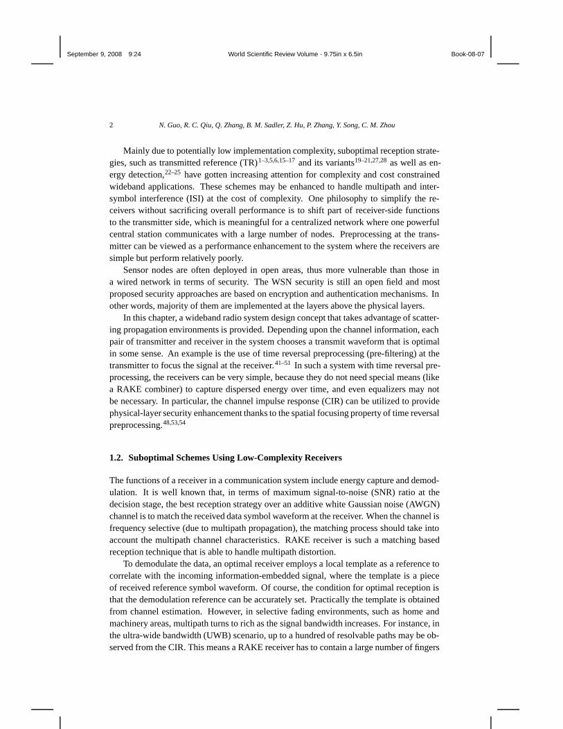
Transmitted reference (TR) is a communication scheme with the reference symbols be-ing transmitted along with the data symbols. In order to eliminate the requirement for chan-nel estimation at the receiver, both the message and the reference are transmitted throughtwo dedicated subchannels separated by time or frequency, where the channel separationis small enough to ensure coherence between the two subchannels. The information bitsmay be modulated in pulse position modulation (PPM) or antipodal format. The receivedup-to-date reference signal is directly used to demodulate the data. Fig.1.1 describes thetime-separated TR scheme. The core of the receiver in a time-separated TR system is adelay line device followed by a correlator. The simplicity is achieved at the cost of perfor-mance penalty in the following two aspects. First of all, half of the total transmit power isspending in transmitting the reference. Secondly, the received reference signal is “dirty”–
September 9, 2008 9:24 World Scientific Review Volume - 9.75in x 6.5in Book-08-07
4 N. Guo, R. C. Qiu, Q. Zhang, B. M. Sadler, Z. Hu, P. Zhang, Y. Song, C. M. Zhou
noise polluted, which results in a non-Gaussian cross-noise term in addition to a Gaussiannoise term in the correlator’s output. The non-Gaussian noise is much stronger than theGaussian noise, leading to significant performance degradation. Aiming at improving theoriginal TR scheme, a number of TR variants have been proposed.
A straight-forward way to reduce the overhead is to reduce percentage of referencesymbols, i.e., only one referenced symbol is transmitted for a block of data symbols (calledstored reference in4), implying that a piece of received reference waveform is stored atthe receiver and serves as a reference for demodulating multiple data symbols. However,the waveform storage can be very expensive. To remove the overhead completely, thereference can be provided through differentially encoding, so that a modulated data bit canbe demodulated by using the previous symbol as reference. This differentially encoded TRis called autocorrelation demodulation in Simon’s book 18 and DTR in the paper by Chaoand Scholtz.20 By eliminating the dedicated reference transmission, the energy efficiencyis improved by about 3 dB.20
The template noise level may be suppressed by averaging (or accumulating) over a fewreceived reference symbols.7 Averaging can be applied to DTR receivers too if decisionfeedback is utilized.21 However, implementing the averaging function at waveform levelrequires storing multiple received symbol waveforms, which is not cheap for either analogor digital approaches.
I&D# 1
T b
I&D# 2
2T b
r(t)
I&D# L
LTb
...
Dec
isio
n
Fig. 1.2. A DTR based multi-symbol detection receiver structure.
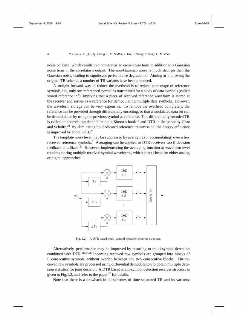
Alternatively, performance may be improved by resorting to multi-symbol detectioncombined with DTR.18,27,28 Incoming received raw symbols are grouped into blocks ofL consecutive symbols, without overlap between any two consecutive blocks. The re-ceived raw symbols are processed using differential demodulation to obtain multiple deci-sion statistics for joint decision. A DTR based multi-symbol detection receiver structure isgiven in Fig.1.2, and refer to the paper 27 for details.
Note that there is a drawback in all schemes of time-separated TR and its variants:
September 9, 2008 9:24 World Scientific Review Volume - 9.75in x 6.5in Book-08-07
Time Reversal for Ultra-wideband Communications: Architecture and Test-bed 5
expensive and bulky delay elements are required at the receivers. This huge disadvan-tage prevents the time-separated TR schemes from being widely accepted. Without usingany delay device, a frequency-separated TR can provide the reference at the cost of fre-quency expansion.15–17 One of proposed frequency-separated TR scheme is called slightlyfrequency-shifted reference (FSR) technique 15 suitable for low data rate applications, andimplementing an FSR receiver is quite easy.
Different from the template-correlation schemes mentioned above, another family ofsuboptimal reception schemes includes energy (square-law) detector and envelop detec-tor. With either of the detectors, both on-off keying (OOK) and pulse position modulation(PPM) can be adopted as modulation schemes. One problem with these two unipodalmodulation schemes is that they cause spectral spikes due to non-zero mean of the sym-bol values. Scrambling encoding can remove the spectral spikes and time hopping (TH)may be considered for both multiple user access and spectral spike reduction. The receiveruses an integrator to accumulate signal energy. For better performance the signal can beweighted prior to integration and there must be a best weighting function depending onthe signal waveform and the noise level.8–12 In fact, implementation of weighting functionis not of low complexity and this contradicts the philosophy of low-complexity receiverdesign. A relatively simpler weighting method is a gating function which is equivalentto the use of a proper integration interval. 13,14,25,51 A practical implementation of a smartintegrator is to control the integrator’s on-duration. Denoted by R b the symbol rate andconsider a received symbol waveform with most of the energy concentrated in an intervalTI . If TI < Tb = 1/Rb, then integrating over the interval TI outperforms integrating overthe interval Tb, since both gather almost the same amount of signal energy but the lattergathers more noise.
All of the discussed suboptimal schemes are of low-complexity in the sense that nochannel estimation is required and they are less sensitive to timing error. A common short-coming is that they are not able to work with typical linear equalization techniques, thusthey are not suitable for applications where ISI exists apparently. Unlike linear receiver,the equivalent discrete channels of some suboptimal schemes behave nonlinearly, where anequivalent discrete-time channel has data input at one end and it outputs decision statisticplus noise at the other end.25,30,31,51 For both DTR and energy detection, their equivalentdiscrete channels can be modeled as25,51
zk = �dTk C�dk + ηk, (1.1)
where subscript k is a symbol timing index, zk is the decision statistic, �dk is a data vectorwhose dimension covers the ISI length in symbol, C is a matrix determined by the channel,and ηk is a noise term. This means that the signal part in the output of the equivalent
discrete channel, i.e., �dTk C �dk
def= Sk, is a nonlinear function of data vector �dk. As a
matter of fact, the equivalent discrete channel represented by S k = �dTk C �dk is a special
case of second-order Volterra model.29,30 In general, zk contains a desired signal and anonlinear inter-symbol-interference (ISI) component that cannot be well handled by normallinear equalization techniques. This fact suggests the use of some waveform level channel
September 9, 2008 9:24 World Scientific Review Volume - 9.75in x 6.5in Book-08-07
6 N. Guo, R. C. Qiu, Q. Zhang, B. M. Sadler, Z. Hu, P. Zhang, Y. Song, C. M. Zhou
shortening techniques.
1.3. Waveform Preprocessing
Modern communication systems rely on analogue and digital signal processing to combatvarious impairments such as noise, channel fading (flat and frequency-selective fading),and interferences. For a given environment, a global optimum system under some sortof criterion delivers the best performance. By“global” we mean joint transmitter-receiveroptimization. However, most existing work on the joint transmitter-receiver optimizationis at symbol-rate level.32–37 It can be expected that by breaking the symbol-rate constraintand allowing continuous-time or fractional-symbol-level processing, the performance canbe improved further. In other words, given a communication channel, we prefer to designa set of transmit waveforms as well as a receiver with proper structure and algorithm, suchthat the system achieves some sort of optimum under some conditions and constraints.The signal processing goals could be capacity-reaching, maximum SNR, and minimummean square error (MMSE), etc. In most wireless communication scenarios the channelcharacteristics are time-varying and up-to-date channel information is only available at thereceivers. This is why traditionally signal processing efforts are focused on the receiverside.
It is reasonable to consider single-carrier pulse-based radio links for WSN applications,since they have potential to be of low-complexity if major receiver-side linear processingfunctions are shifted to the transmitter side. It is well known that low probability of in-terception and low probability of detection (LPI/LPD) can be easily achieved using pulse-based signaling. Also, a narrow-pulse-based single-carrier system can be used for rangingor penetration radar purposes.
A unique issue associated with wireless communications is frequency-selective fadingcaused by multipath propagation. As for interferences in radio systems, ISI and inter-userinterference (IUI) are typically concerned. Listed below are some receiver-based schemesto handle noise, multipath impact and interferences.
• Matched filter (MF): it is placed at the receiver and matches the given transmitsymbol (or chip) waveform; for AWGN noise, it maximizes the SNR at the peakof the MF’s output.
• RAKE receiver: a family of technique to collect the signal energy dispersed overmultipath components; an ideal RAKE receiver actually matches the overall re-ceived waveform; when major paths are resolvable, a practical RAKE receiverstructure can be a combination of a regular chip-level MF and a multipath com-biner functioning as a finite impulse response (FIR) filter; a RAKE receiver oper-ates at fractional-symbol (or fractional-chip) rate.
• Equalization: a symbol-rate discrete-time processing to remove or reduce ISI; anequalizer is placed at the receiver, usually taking symbol-rate samples from the

September 9, 2008 9:24 World Scientific Review Volume - 9.75in x 6.5in Book-08-07
Time Reversal for Ultra-wideband Communications: Architecture and Test-bed 7
MF’s output as its input.
• (Receiver-based) multi-user detection: this is a broad range of techniques thatremove or reduce IUI; the multi-user detection operates at symbol-rate.
When channel and/or multi-user information is available at the transmitter, it seems nostrong reason not to use it. Recently, transmitter based signal processing, or preprocess-ing, has received increasing attention. Preprocessing can be time-reversal pre-filtering (orpre-RAKE), pre-equalization, multi-user precoding, or some processing for a set of com-promised goals. Preprocessing can be used along in a transmitter-centric system wheretraditional receiver-based signal processing is shifted to the transmitters to simplify the re-ceivers. It can also works with receiver-based signal processing to achieve joint transmitter-receiver optimization.
Our special interest is on preprocessing at fractional-symbol rate (or simply, waveformpreprocessing), in conjunction with a suboptimal receiver. Below are two examples ofsymbol waveforms.
• Pulse shaping: it uses a transmitter-side filter to create a transmit waveform thathas desired roll-off spectrum; traditional pulse shapes include raised cosine andtruncated sinc functions, etc.
• Maximum-SNR transmit waveform: a transmit symbol waveform to achieve themaximum SNR at the MF’s output; it is an eigenfunction of the CIR autocorre-lation (implying the CIR has to be known first); and a homogeneous Fredholmintegral equation needs to solved for the eigenfunction with the strongest channelgain.38,40
The transmit waveform optimization problem can be further stated in details as follows.It is well known that the optimum receiver matches the whole symbol waveform distortedby the channel, not the transmitted symbol waveform. However, from system optimizationpoint of view, such a waveform matching alone is not enough. We can further maximizeSNR at the receiver by carefully designing the transmitted waveform. 38,40
Given the channel impulse response h(t) and fixed transmitted power P t, we wish toachieve the maximum SNR at the receive by jointly designing the transmitted waveformand a good receiver. This problem has been discussed in 38 for communication over tro-poscatter channels and in40 for radar detection.
Assuming the transmitted pulse p(t) (to be optimized) is confined to the symmetrictime interval [−T/2, T/2]. The energy of transmitted pulse is then
Ep =∫ T/2
−T/2
|p(t)|2 dt . (1.2)
It follows from detection theory that the best receiver is still a MF matched to the receivedwaveform p(t) ∗ h(t), where h(t) is the CIR and “∗” denotes convolution operation. The

September 9, 2008 9:24 World Scientific Review Volume - 9.75in x 6.5in Book-08-07
8 N. Guo, R. C. Qiu, Q. Zhang, B. M. Sadler, Z. Hu, P. Zhang, Y. Song, C. M. Zhou
(maximum) SNR at the output of such a MF is given by.
SNR = 2Ey/N0, (1.3)
where Ey =∫ T/2
−T/2|p(t) ∗ h(t)|2 dt is the received signal energy. The problem is then
reduced to find the optimum p(t) such that Ey is maximized, under the constraint of fixedEp.
It has been shown in39 (p.125) and40 that the optimum p(t) can be obtained by solvingthe following homogeneous Fredholm integral equation
μnφn(t) =∫ T/2
−T/2
κ(t − τ)φn(τ) dτ , (1.4)
and let p(t) = φ0(t), where φ0(t) is the eigenfunctions corresponding to the maximumeigenvalue μ0 and the kernel κ(t) is the autocorrelation of the CIR: κ(t) = h(t) ∗ h(−t).When convolved with the kernel over the interval [−T/2, T/2], pulse waveform φ 0(t) re-produces itself, scaled by a constant μ0. With optimum p(t) = φ0(t) we achieve themaximum SNR
SNR = 2μ0Ep/N0. (1.5)
It is worth noting that this maximum-SNR waveform may lead to severe ISI if theduration of p(t) = φ0(t) exceeds the symbol duration, which is one reason preventing thescheme from being widely applicable.
DigitalModulator
Antenna
PA
LNACoefficientEstimator
Pre-filter
Pulse FilterDigital FIR
Filter
RF front-end
PA = Power AmplifierLNA = Low Noise Amplifier
Fig. 1.3. A conceptual transmitter structure capable of preprocessing (in the RF front-end frequency up- anddown-conversion may be used to shift the signal frequency).
A transmitter capable of general waveform synthesizing or arbitrary waveform gen-erating would be the ultimate goal of preprocessing. A digital FIR filter based waveformgenerator would be flexible and become more and more feasible as the semiconductor tech-nology advances. A common structure of this type of waveform generators is a digital FIRfilter followed by an analogue interpolating or shaping filter as illustrated in Fig.1.3. How-ever, for any digital implementation, sampling rate as well as quantization resolution arelimited. From a perspective of implementation, trade-off between performance and fea-sibility or cost must be made. Time reversal with mono-bit or ternary quantization andsub-Nyquist rate sampling has been proved working satisfactorily, according to computersimulation and test-bed based experiment.48,51 The practical limitations should be consid-ered in the performance optimization.
September 9, 2008 9:24 World Scientific Review Volume - 9.75in x 6.5in Book-08-07
Time Reversal for Ultra-wideband Communications: Architecture and Test-bed 9
Rx
Tx
...
c1(t)
c2(t)
cM (t)
h1(t)
h2(t)
hM (t)
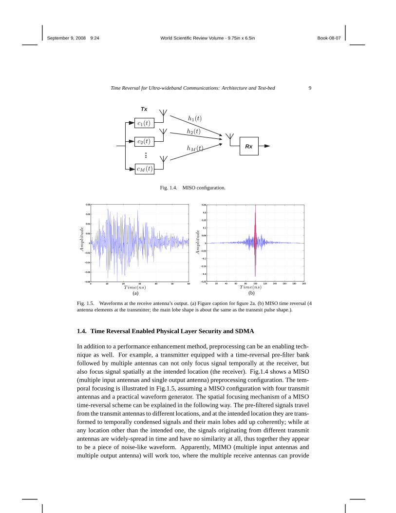
Fig. 1.4. MISO configuration.
0 10 20 30 40 50 60−0.08
−0.06
−0.04
−0.02
0
0.02
0.04
0.06
0.08
Time(ns)
Am
pli
tude
(a)
0 20 40 60 80 100 120 140 160 180 200−0.25
−0.2
−0.15
−0.1
−0.05
0
0.05
0.1
0.15
0.2
0.25
Time(ns)
Am
pli
tude
(b)
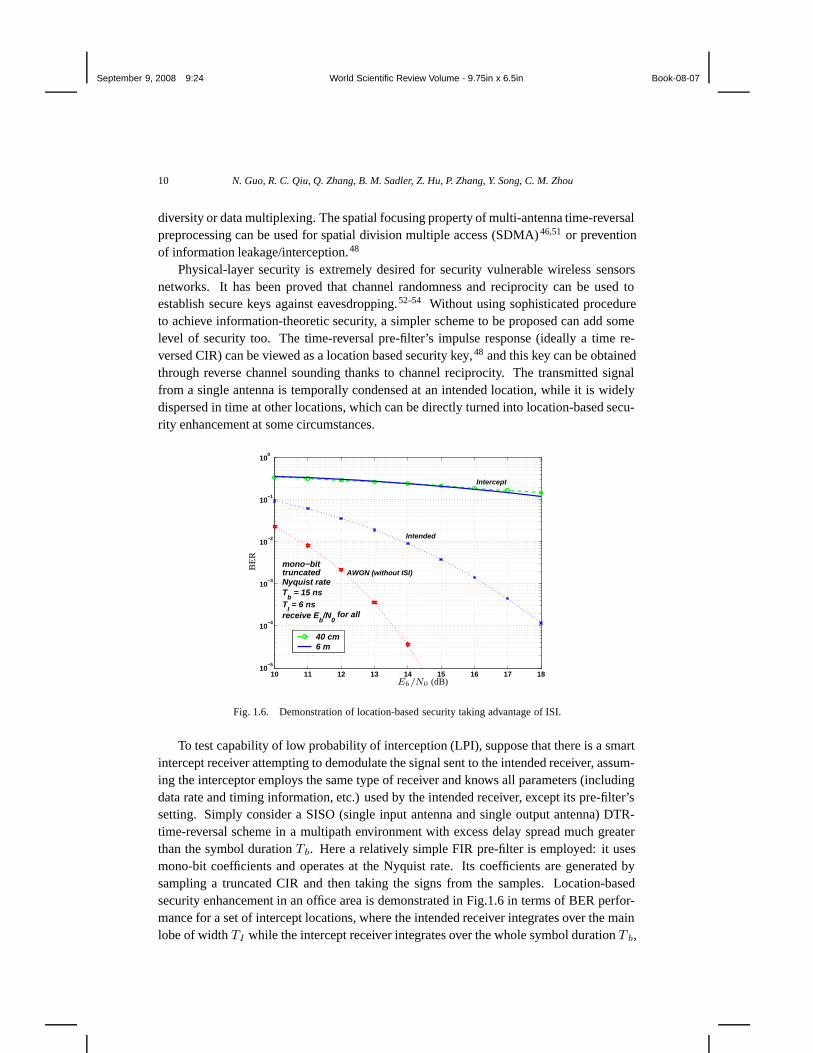
Fig. 1.5. Waveforms at the receive antenna’s output. (a) Figure caption for figure 2a. (b) MISO time reversal (4antenna elements at the transmitter; the main lobe shape is about the same as the transmit pulse shape.).
1.4. Time Reversal Enabled Physical Layer Security and SDMA
In addition to a performance enhancement method, preprocessing can be an enabling tech-nique as well. For example, a transmitter equipped with a time-reversal pre-filter bankfollowed by multiple antennas can not only focus signal temporally at the receiver, butalso focus signal spatially at the intended location (the receiver). Fig.1.4 shows a MISO(multiple input antennas and single output antenna) preprocessing configuration. The tem-poral focusing is illustrated in Fig.1.5, assuming a MISO configuration with four transmitantennas and a practical waveform generator. The spatial focusing mechanism of a MISOtime-reversal scheme can be explained in the following way. The pre-filtered signals travelfrom the transmit antennas to different locations, and at the intended location they are trans-formed to temporally condensed signals and their main lobes add up coherently; while atany location other than the intended one, the signals originating from different transmitantennas are widely-spread in time and have no similarity at all, thus together they appearto be a piece of noise-like waveform. Apparently, MIMO (multiple input antennas andmultiple output antenna) will work too, where the multiple receive antennas can provide
September 9, 2008 9:24 World Scientific Review Volume - 9.75in x 6.5in Book-08-07
10 N. Guo, R. C. Qiu, Q. Zhang, B. M. Sadler, Z. Hu, P. Zhang, Y. Song, C. M. Zhou
diversity or data multiplexing. The spatial focusing property of multi-antenna time-reversalpreprocessing can be used for spatial division multiple access (SDMA) 46,51 or preventionof information leakage/interception.48
Physical-layer security is extremely desired for security vulnerable wireless sensorsnetworks. It has been proved that channel randomness and reciprocity can be used toestablish secure keys against eavesdropping.52–54 Without using sophisticated procedureto achieve information-theoretic security, a simpler scheme to be proposed can add somelevel of security too. The time-reversal pre-filter’s impulse response (ideally a time re-versed CIR) can be viewed as a location based security key,48 and this key can be obtainedthrough reverse channel sounding thanks to channel reciprocity. The transmitted signalfrom a single antenna is temporally condensed at an intended location, while it is widelydispersed in time at other locations, which can be directly turned into location-based secu-rity enhancement at some circumstances.
10 11 12 13 14 15 16 17 1810
−5
10−4
10−3
10−2
10−1
100
40 cm6 m
Intercept
AWGN (without ISI)
Intended
mono−bittruncatedNyquist rateT
b = 15 ns
TI = 6 ns
receive Eb/N
0 for all
Eb/N0 (dB)
BE
R
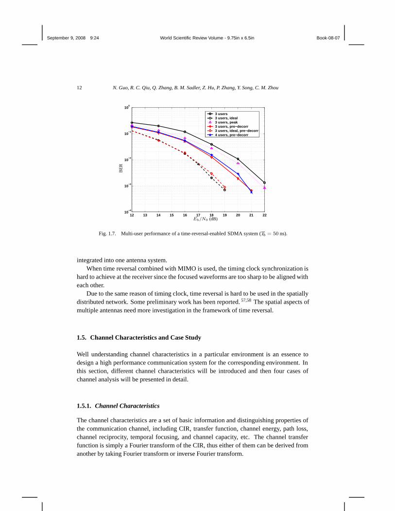
Fig. 1.6. Demonstration of location-based security taking advantage of ISI.
To test capability of low probability of interception (LPI), suppose that there is a smartintercept receiver attempting to demodulate the signal sent to the intended receiver, assum-ing the interceptor employs the same type of receiver and knows all parameters (includingdata rate and timing information, etc.) used by the intended receiver, except its pre-filter’ssetting. Simply consider a SISO (single input antenna and single output antenna) DTR-time-reversal scheme in a multipath environment with excess delay spread much greaterthan the symbol duration Tb. Here a relatively simple FIR pre-filter is employed: it usesmono-bit coefficients and operates at the Nyquist rate. Its coefficients are generated bysampling a truncated CIR and then taking the signs from the samples. Location-basedsecurity enhancement in an office area is demonstrated in Fig.1.6 in terms of BER perfor-mance for a set of intercept locations, where the intended receiver integrates over the mainlobe of width TI while the intercept receiver integrates over the whole symbol duration T b,

September 9, 2008 9:24 World Scientific Review Volume - 9.75in x 6.5in Book-08-07
Time Reversal for Ultra-wideband Communications: Architecture and Test-bed 11
Eb/N0 is measured at the intended receiver, and both the intended and intercept receiversare about 6 m apart from the transmitter. Surprisingly, even just several tens of centimetersaway from the intended receiver, although the interceptor has known all critical parame-ters, due to severe ISI, it has very little chance to understand what it is listening to, whichmeans security has been greatly enhanced without using any traditional encryption method.More important, the “security key” is obtained at the physical layer based on the scatteringnature, without consuming additional radio resource. In this example the intended receiversuffers from some ISI impact, but it can be reduced if some countermeasure is taken.
If equipped with multiple transmit antennas, the transmitted energy would truly focus atthe intended location, achieving prevention of information leakage from an electromagnetic(EM) radiation point of view.
Another interesting feature of time reversal is its SDMA enabling. Note that the tem-poral/spatial focusing mechanism is not able to remove ISI and IUI completely. Accordingto some indoor experiments, an SDMA multiuser system solely based on time reversalcan suffer from strong IUI because of cross-correlations between the radio links, and evenincreasing the number of transmit antennas cannot fully solve the problem. 51 For demon-stration purpose, consider a rather simple time-reversal SDMA system using pulse basedDTR scheme. If time reversal combined with pulsed signaling, a pulse train would appearat the intended receiver. Shrinking the integration window to capture the signal peaks atthe receiver could result in a lowered SNR, but it reduces the IUI impact as well, sincethe signal to interference ratio around a signal peak is higher. Overall speaking, a narrowintegration window may lead to a higher SINR (Signal to Interference plus Noise Ratio)and better performance, if the impact of IUI is much more significant than that of thebackground noise. For simplicity, assume the receiver samples the signal at peak instants,without integrating the signal over a main-lobe interval. To reduce the IUI impact further,a stage of decorrelation precoding (of course, other types of multi-user precoding can beconsidered too) is added to the transmitter to remove the IUI at the instants of signal peaks.
Shown in Fig.1.7 are a set of simulation results for multi-user schemes with differentsettings, where by default the pre-filter is significantly simplified (mono-bit time rever-sal), “ideal” refers to an ideal pre-filter, and “pre-decorr” refers to decorrelation precodingat the transmitter and sampling peaks at the receivers. The BER performance is mainlyaffected by the accuracy of pre-filtering, ISI, IUI as well as integration window size T I .Two integration window sizes are considered here: TI = 6 ns (default) and TI = 0.1 ns(for peak capturing method). Based on these trials we have the following observations:(1) the mono-bit time-reversal scheme without precoding performs worst as expected; (2)the peak-sampling scheme yields improved performance; (3) decorrelation precoding com-bined with peak sampling improves the performance further and leads to more than 1.5 dBgain over the the mono-bit time-reversal scheme; and (4) in the ideal time-reversal scenario,applying decorrelation precoding plus peak sampling does not provide additional gain.
Time reversal combined with MISO is feasible, since the identical timing clock isshared by the multiple waveform generators. The system is especially promising whenthe number of antennas is large, say 16, 64, 128. The large number of antennas can be
September 9, 2008 9:24 World Scientific Review Volume - 9.75in x 6.5in Book-08-07
12 N. Guo, R. C. Qiu, Q. Zhang, B. M. Sadler, Z. Hu, P. Zhang, Y. Song, C. M. Zhou
12 13 14 15 16 17 18 19 20 21 2210
−4
10−3
10−2
10−1
100
3 users3 users, ideal3 users, peak3 users, pre−decorr3 users, ideal, pre−decorr4 users, pre−decorr
Eb/N0 (dB)
BE
R
Fig. 1.7. Multi-user performance of a time-reversal-enabled SDMA system (Tb = 50 ns).
integrated into one antenna system.When time reversal combined with MIMO is used, the timing clock synchronization is
hard to achieve at the receiver since the focused waveforms are too sharp to be aligned witheach other.
Due to the same reason of timing clock, time reversal is hard to be used in the spatiallydistributed network. Some preliminary work has been reported. 57,58 The spatial aspects ofmultiple antennas need more investigation in the framework of time reversal.
1.5. Channel Characteristics and Case Study
Well understanding channel characteristics in a particular environment is an essence todesign a high performance communication system for the corresponding environment. Inthis section, different channel characteristics will be introduced and then four cases ofchannel analysis will be presented in detail.
1.5.1. Channel Characteristics
The channel characteristics are a set of basic information and distinguishing properties ofthe communication channel, including CIR, transfer function, channel energy, path loss,channel reciprocity, temporal focusing, and channel capacity, etc. The channel transferfunction is simply a Fourier transform of the CIR, thus either of them can be derived fromanother by taking Fourier transform or inverse Fourier transform.

September 9, 2008 9:24 World Scientific Review Volume - 9.75in x 6.5in Book-08-07
Time Reversal for Ultra-wideband Communications: Architecture and Test-bed 13
1.5.1.1. Time Domain Measurement of Channel Impulse Response (CIR)
The CIR is a time domain characteristic and it can be represented using the well-knowtapped delay line (TDL) model. Time domain channel sounding is straight forward toget the CIR. In a time domain channel sounding experiment, the transmitter sends a pulsetrain through a transmit antenna to sound the channel and the waveform is picked up by areceive antenna and recorded as measurement data. One difficulty in time domain channelsounding is to generate sounding pulses that contain most signal energy in the frequencyband of interest and are easy to be captured and processed. A digital sampling oscilloscope(DSO) is typically used to capture the waveform and store the data, where the samplingrate have to be sufficiently high to capture the details. The CIR in tap delay line modelcan be estimated from the received noisy waveform using “CLEAN”, a matching pursuitalgorithm.
1.5.1.2. Frequency Domain Measurement of Channel Transfer Function
A channel transfer function gives the complex gain of the channel at different frequencies,thus frequency domain channel sounding is recommended to get channel transfer functiondirectly. With a vector network analyzer (VNA), a frequency domain channel soundingsetup would be quite easy. The VNA functions as both a transmitter and a receiver; itsweeps a set of sinusoid signals within the pre-determined frequency band and generatesthe S-parameters containing the complex transfer function. Frequency domain channelsounding can cover wide range of frequencies, as far as the sweep time is much less thanthe channel coherent time. One disadvantage in a VNA based high frequency measurementis that the transmission range is limited due to large attenuation of the connecting cables.Because the frequency range is limited for a VNA, a rectangular spectral window is auto-matically posed. However, the spectral window may be reshaped to take into account anyspecific filter effect.
1.5.1.3. Channel Energy
The energy of the channel is defined as
Eh =∫ Th
0
h2(t)dt (1.6)
where h(t) is CIR and Th is its support.
1.5.1.4. Path Loss
The received power is given by
Pr = Pt − PL + Gt + Gr (1.7)
where Pr and Pt are the receive and transmit powers in dBm, respectively; Gr and Gt arethe receive and transmit antenna gains in dBi, respectively; and PL is the path loss in dB.

September 9, 2008 9:24 World Scientific Review Volume - 9.75in x 6.5in Book-08-07
14 N. Guo, R. C. Qiu, Q. Zhang, B. M. Sadler, Z. Hu, P. Zhang, Y. Song, C. M. Zhou
The path loss between a pair of antennas is the reduction in power density of an electro-magnetic wave as it propagates through space. It takes into account many physics effectsincluding free-space path “loss”, refraction, diffraction, reflection and absorption. Path lossis environment dependent and it is a function of frequency and distance. Practically pathloss can be calculated using formula
PL (d, f) = PL (d0, f) + 10n(f) log10
(d
d0
)(1.8)
where n(f) is the path loss exponent, f is the frequency of interest, d is the distancebetween the transmitter and the receiver, and d0 is the reference distance. n(f) is equal to2 for propagation in free-space. A path loss exponent greater than 2 means the propagationenvironment is relatively lossy, while a tunnel or a hallway act as a waveguide, resulting ina path loss exponent less than 2.
1.5.1.5. Channel Reciprocity
A real-time CIR is the key information to achieve the optimum performance in a wirelesscommunication system, and channel sounding and estimation are required to generate theup-to-date CIR. Channel reciprocity refers to similarity of a pair of opposite-direction chan-nels between two sites, where both the effect of propagation media and the effect of circuitsat the two ends are taken into account. Perfect channel reciprocity can benefit a two-waywireless communication system, because channel sounding and estimation based on onelink can be used for both forward link and reverse link. However, in reality, the channelreciprocity is not always obvious since there are many unpredictable nonlinear physics phe-nomena associated with the media and the circuits. This motivates experimental validationof channel reciprocity.
1.5.1.6. Relative Temporal Focusing as a Function of Locations
As mentioned before, pre-filtering (i.e., time reversal) can make the effective CIR tempo-rally focusing and spatial focusing can be achieved using a bank of pre-filters followedby an array of antennas. Considering here a time reversal pre-filtering system with a sin-gle transmitter using a time reversed CIR as the pre-filter coefficients. Let the intendedreceiver location be represented by r0 and the unintended receiver location by r i. Corre-spondingly, denote h(r0, t) and h(ri, t) the CIRs for the locations r0 and ri, respectively.Relative temporal focusing at any location ri with respect to the intended location r0 canbe characterized by a metric D(r0, ri) called directivity, which is defined as
D(r0, ri) =max|Rhh(r0, ri, t)|2max|Rhh(r0, r0, t)|2 (1.9)
where Rhh(r0, r0, t) is a CIR autocorrelation for the intended receiver and Rhh(r0, ri, t)is a crosscorrelation of the two CIRs. Rhh(r0, r0, t) and Rhh(r0, ri, t) are given by
Rhh(r0, r0, t) = h(r0,−t) ∗ h(r0, t), (1.10)

September 9, 2008 9:24 World Scientific Review Volume - 9.75in x 6.5in Book-08-07
Time Reversal for Ultra-wideband Communications: Architecture and Test-bed 15
Rhh(r0, ri, t) = h(r0,−t) ∗ h(ri, t). (1.11)
1.5.1.7. Theoretical Spectral Efficiency
To evaluate the overall effects of the channel and different spectrum-shaping schemes, spec-tral efficiencies are calculated. The spectrum-shaping schemes to consider include waterfilling, time reversal, channel inverse and constant power spectrum density (PSD). A zero-mean band-limited Gaussian random data source which has maximum entropy is used forall different spectrum-shaping schemes. For the sake of simplicity, we further assume thedata source has a flat in-band spectrum. When the water-filling spectral shape is applied,the spectral efficiency reached the maximum, i.e., the channel capacity. Channel capacityis an important channel characteristic and can be served as a performance bound to guidesystem design.
a(t)x(t) h(t)
s(t)n(t)
r(t)
Fig. 1.8. Block diagram of a SISO system.
Fig.1.8 shows the block diagram of a SISO system, where the input signal a(t) isa band-limited white Gaussian random process with zero mean, bandwidth W and unitone-sided PSD, x(t) is the spectrum-shaping pre-filter, s(t) is the transmit signal, h(t)represents CIR, n(t) is the additive white Gaussian noise with one-sided PSD N0, andr(t) represents the received signal. Their Fourier transforms are denoted by A(f), X(f),S(t), H(f), N(f) and R(f), respectively. Assume the support of A(f) is [f0, f1], so thatW = f1 − f0.
The transmitted power is
P =∫ f1
f0
RS(f)df, (1.12)
where RS(f) is the one-sided PSD of the transmitted signal S(t),56 and it is given by
RS(f) = |X(f)|2. (1.13)
The noise power at the receiver is expressed as
N = N0 (f1 − f0) . (1.14)
The SNR at the transmitter, denoted by ρ, is
ρ =P
N. (1.15)

September 9, 2008 9:24 World Scientific Review Volume - 9.75in x 6.5in Book-08-07
16 N. Guo, R. C. Qiu, Q. Zhang, B. M. Sadler, Z. Hu, P. Zhang, Y. Song, C. M. Zhou
Denoting R the transmit bit rate, the spectral efficiency in bits/s/Hz can be expressed as
R
W=
∫ f1
f0log2 (1 + RS(f)|H(f)|2
N0)df
f1 − f0(1.16)
When water filling is used to form the spectrum-shaping pre-filter, we have
RS(f) = (μ − N0
|H(f)|2 )+ (1.17)
where (x)+ = max[0, x], the constant μ is the water level chosen to satisfy the powerconstraint with equality ∫ f1
f0
RS(f)df = P, (1.18)
and the spectral efficiency reaches the maximum, i.e., the channel capacity
C
W=
∫ f1
f0(log2 (μ|H(f)|2
N0))+df
f1 − f0. (1.19)
When time reversal is used, it follows that
X(f) =√
P∫ f1
f0|H(f)|2df
H∗(f), (1.20)
where ∗ means complex conjugate and the spectral efficiency is
R
W=
∫ f1
f0log2 (1 + ρ(f1−f0)|H(f)|4∫ f1
f0|H(f)|2df
)df
f1 − f0. (1.21)
For channel inverse is used, we have
X(f) =
√P∫ f1
f01
|H(f)|2 df
H(f)(1.22)
and
R
W= log2 (1 +
ρ(f1 − f0)∫ f1
f0
1|H(f)|2 df
). (1.23)
Finally, if the transmitted signal has the constant PSD from f0 to f1, then
RS(f) =P
(f1 − f0), (1.24)
and
R
W=
∫ f1
f0log2 (1 + ρ|H(f)|2)df
f1 − f0. (1.25)
September 9, 2008 9:24 World Scientific Review Volume - 9.75in x 6.5in Book-08-07
Time Reversal for Ultra-wideband Communications: Architecture and Test-bed 17
1.5.2. Case Study
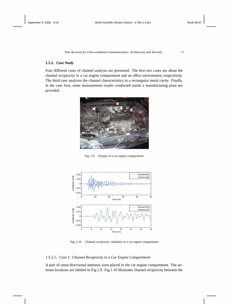
Four different cases of channel analysis are presented. The first two cases are about thechannel reciprocity in a car engine compartment and an office environment, respectively.The third case analyzes the channel characteristics in a rectangular metal cavity. Finally,in the case four, some measurement results conducted inside a manufacturing plant areprovided.
Fig. 1.9. Display of a car engine compartment.
0 10 20 30 40 50
−0.02
−0.01
0
0.01
0.02
Time (ns)
Am
plitu
de (
Vol
t)
2 4 6 8 10 12 14 16
−0.02
−0.01
0
0.01
0.02
Time (ns)
Am
plitu
de (
Vol
t)
forward linkreverse link
forward linkreverse link
Fig. 1.10. Channel reciprocity validation in a car engine compartment.
1.5.2.1. Case 1: Channel Reciprocity in a Car Engine Compartment
A pair of omni-directional antennas were placed in the car engine compartment. The an-tenna locations are labeled in Fig.1.9. Fig.1.10 illustrates channel reciprocity between the
September 9, 2008 9:24 World Scientific Review Volume - 9.75in x 6.5in Book-08-07
18 N. Guo, R. C. Qiu, Q. Zhang, B. M. Sadler, Z. Hu, P. Zhang, Y. Song, C. M. Zhou
forward link A-G and the reverse link G-A, where link A-G corresponds to transmissionfrom antenna A to antenna G, and link G-A corresponds to a reverse transmission. Tworeceived waveforms measured in the forward and reverse links almost coincide with eachother. The correlation between these two waveforms is as high as about 0.98, so that chan-nel reciprocity can be declared from the engineering point of view. The bottom plot inFig.1.10 shows a closer look of the upper plot. It was found that whether the engine was onor off, no difference could be observed from measurement. Moreover, similar results wereobtained for different pairs of antenna locations.
Although time-domain measurement was used, the same conclusion can be expectedfor frequency-domain validation.
Rx
Tx
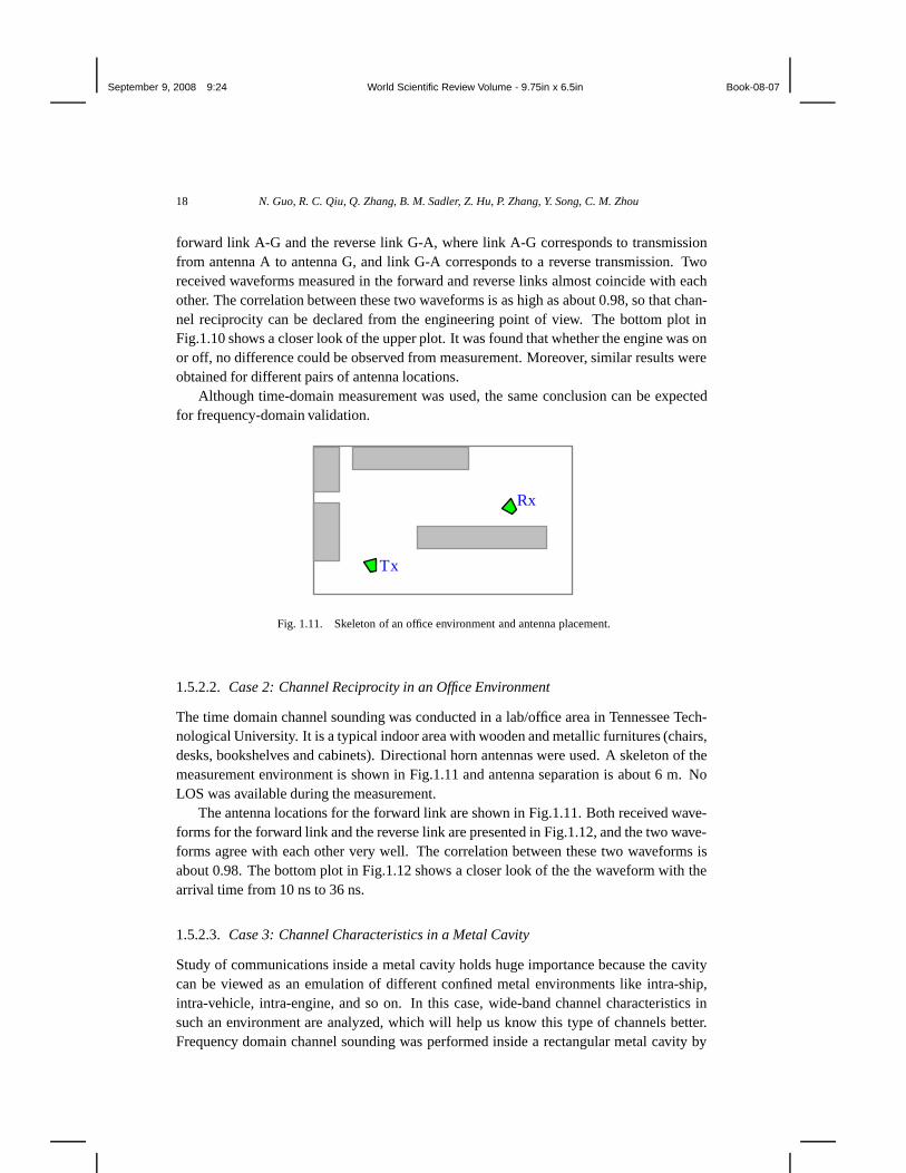
Fig. 1.11. Skeleton of an office environment and antenna placement.
1.5.2.2. Case 2: Channel Reciprocity in an Office Environment
The time domain channel sounding was conducted in a lab/office area in Tennessee Tech-nological University. It is a typical indoor area with wooden and metallic furnitures (chairs,desks, bookshelves and cabinets). Directional horn antennas were used. A skeleton of themeasurement environment is shown in Fig.1.11 and antenna separation is about 6 m. NoLOS was available during the measurement.
The antenna locations for the forward link are shown in Fig.1.11. Both received wave-forms for the forward link and the reverse link are presented in Fig.1.12, and the two wave-forms agree with each other very well. The correlation between these two waveforms isabout 0.98. The bottom plot in Fig.1.12 shows a closer look of the the waveform with thearrival time from 10 ns to 36 ns.
1.5.2.3. Case 3: Channel Characteristics in a Metal Cavity
Study of communications inside a metal cavity holds huge importance because the cavitycan be viewed as an emulation of different confined metal environments like intra-ship,intra-vehicle, intra-engine, and so on. In this case, wide-band channel characteristics insuch an environment are analyzed, which will help us know this type of channels better.Frequency domain channel sounding was performed inside a rectangular metal cavity by

September 9, 2008 9:24 World Scientific Review Volume - 9.75in x 6.5in Book-08-07
Time Reversal for Ultra-wideband Communications: Architecture and Test-bed 19
0 10 20 30 40 50 60 70 80 90 100−0.03
−0.02
−0.01
0
0.01
0.02
0.03
Time (ns)
Rec
eive
d S
igna
l: A
mpl
itude
(V
)
Forward LinkReverse Link
10 15 20 25 30 35−0.03
−0.02
−0.01
0
0.01
0.02
0.03
Time (ns)
Rec
eive
d S
igna
l: A
mpl
itude
(V
)
Forward LinkReverse Link
Fig. 1.12. Comparison of the received waveforms of the two links in an office environment.
Tx Antenna Rx Antenna
4 meters
16 feet
8 feet
4 feet
4 feet
VNA
Fig. 1.13. Setup for channel sounding in rectangular metal cavity.
using a VNA. The dimension of the cavity is 16 feet by 8 feet by 8 feet, and the surfacematerial of the cavity is aluminum. The channel sounding setup is illustrated in Fig.1.13.Omni-directional antennas were used, with the transmit antenna being fixed and the receiveantenna sliding along the horizontal central line in the cavity. The distance between trans-mitter antenna and receiver antenna varied from 0.5 m to 4 m in a step of 0.5 m. Table1.5.2.3 lists the main parameters for this experiment. Measurement were also performed inan office and a hallway for comparison purpose.
Channel transfer functions and the corresponding passband CIRs for the three differentenvironments are depicted in Fig.1.14. In all the cases, the distance between the transmitterantenna and the receiver antenna is about 4 m. It is observed that the delay spread ofchannel is about 800 ns in the cavity, while in the office and the hallway they are less than200 ns. The in-cavity CIR with large delay spread consists of a large number of multipathswhich does not appear in the office and the hallway.

September 9, 2008 9:24 World Scientific Review Volume - 9.75in x 6.5in Book-08-07
20 N. Guo, R. C. Qiu, Q. Zhang, B. M. Sadler, Z. Hu, P. Zhang, Y. Song, C. M. Zhou
TABLE 1.5.2.3 Measurement Parameters setup.
Parameter value
Frequency Band 3 GHz-10 GHzNumber of Points 7001
Transmission Power 10 dBmFrequency Step 1 MHz
Antenna Polarization verticalNumber of Averaging 128
Antenna Height 1.35 m
Channel energy comparison is shown in Fig.1.15. It is can be seen that the channelenergy in the cavity is much higher than those in the office and the hallway. For example,when the distance between the antennas is 3 m, the channel energy in the cavity is nearly20 dB higher than those in the other two environments. Moreover, the channel energy inthe cavity is very stable as the antenna separation changes, but the channel energies in theoffice or the hallway drop apparently as the antenna separation increases from 0.5 m to 3m.
For analyzing temporal focusing vs. locations, the transmit antenna was fixed on thehorizontal central line, and the receive antenna was moved along a line that is 4 m awayfrom the transmit antenna and perpendicular with the horizontal central line. As shown inFig.1.16, 18 receive antenna locations with 3-cm separation were tested. In evaluation weconsider the first location r0 as the intended receiver and all others (ri, i = 1, 2, · · · , 17) asthe unintended receivers. The received waveform autocorrelation R hh(r0, r0, t) betweenthe transmitter and the intended receiver is presented in Fig.1.17(a), and the crosscorre-lation Rhh(r0, r1, t) between the transmitter and the unintended receiver at location r 1 ispresented in Fig.1.17(b).
The directivity in the cavity is calculated by using Equation 1.9 and shown in Fig.1.18.It is observed that the directivity drops by almost 20 dB when the unintended receiver isonly 3 cm away from the intended receiver, which implies that communication securityinside a metal cavity can be enhanced by taking advantage of the rich scattering property.
Finally, spectral efficiencies are calculated based on the measured data. Fig.1.19 showsspectral efficiencies in the cavity for different spectrum-shaping schemes. Among the fourspectrum-shaping schemes, water filling, as expected, gives the maximum spectral effi-ciency (actually, the channel capacity), while channel inverse gives the minimum. At lowtransmit SNR time reversal performs better than constant PSD, but the spectral efficiency ofconstant PSD approaches that of water filling at high transmit SNR. Fig.1.20 shows spectralefficiencies of water filling (i.e., channel capacities) in the cavity, the office and the hallwaywhen water filling is used. The channel capacity in the cavity is much higher than those inthe other two environments, suggesting that confined metal environments have potential tosupport very high data rate transmission.

September 9, 2008 9:24 World Scientific Review Volume - 9.75in x 6.5in Book-08-07
Time Reversal for Ultra-wideband Communications: Architecture and Test-bed 21
3 4 5 6 7 8 9 10
x 109
−80
−70
−60
−50
−40
−30
−20
Frequency (Hz)
Mag
nitu
de(d
B)
4 meters
(a) Channel transfer function in cavity.
0 200 400 600 800 1000−8
−6
−4
−2
0
2
4
6
8x 10
−4
Time(ns)
Cha
nnel
Impu
lse
Res
pons
e (V
)
4 meters
(b) The passband CIR in cavity.
3 4 5 6 7 8 9 10
x 109
−110
−100
−90
−80
−70
−60
−50
−40
Frequency (Hz)
Mag
nitu
de(d
B)
4 meters
(c) Channel transfer function in office.
0 200 400 600 800 1000−8
−6
−4
−2
0
2
4
6
8x 10
−4
Time(ns)
Cha
nnel
Impu
lse
Res
pons
e (V
)4 meters
(d) The passband CIR in office.
3 4 5 6 7 8 9 10
x 109
−100
−90
−80
−70
−60
−50
−40
Frequency (Hz)
Mag
nitu
de(d
B)
4 meters
(e) Channel transfer function in hallway.
0 200 400 600 800 1000−8
−6
−4
−2
0
2
4
6
x 10−4
Time(ns)
Cha
nnel
Impu
lse
Res
pons
e (V
)
4 meters
(f) The passband CIR hallway.
Fig. 1.14. Channel transfer function and the corresponding passband CIR in different environments.
1.5.2.4. Case 4: Radio Channel Measurements in a Manufacturing Plant
An industry environment like a in-building manufacturing area is a very complex environ-ment for the electromagnetic wave propagation. Due to its complexity, it is hard to evaluatethe channel using some prediction models which require enormous number of geometricinformation about the environment. It seems that measurement is the only way to study

September 9, 2008 9:24 World Scientific Review Volume - 9.75in x 6.5in Book-08-07
22 N. Guo, R. C. Qiu, Q. Zhang, B. M. Sadler, Z. Hu, P. Zhang, Y. Song, C. M. Zhou
0.5 1 1.5 2 2.5 3 3.5 4−60
−55
−50
−45
−40
−35
Distance(m)
Ene
rgy
of c
hann
el im
puls
e re
spon
se (
dB)
Rectangular metal cavityOfficeHallway
Fig. 1.15. Energy of channel in rectangular metal cavity, office and hallway environments
Tx Antenna
RxAntenna
4 meters
16 feet
8 feet
4 feet
4 feet
VNA
3 cm 0r
1r
2r
17r
Fig. 1.16. Setup for analyzing relative temporal focusing.
TABLE 1.5.2.3 Path loss exponents for different measurement areas.
Environment Antenna distance Path Loss Exponent
Beside the product line (LOS) 25m 1.68Chassis area (NLOS) 30m 2.26
Crosslane (NOLS) 33m 2.51Along the product line (NLOS) 60m 2.10
Dense area (NLOS) 68m 2.33
channel characteristics in such type of environments. In this case study, path loss expo-nent n is calculated based on the measurement data collected inside a manufacturing plant.As for transmit-receive antenna pairs, several combinations, including Omni-Omni, Omni-Horn and Horn-Horn were tested. An omni-directional antenna has wide coverage angleat the penalty of short transmission range, while a horn antenna can transmit far but hasa narrow coverage angle. The mentioned three antenna combinations can can fit differentapplications and requirements. Path loss exponents for different measurement areas are

September 9, 2008 9:24 World Scientific Review Volume - 9.75in x 6.5in Book-08-07
Time Reversal for Ultra-wideband Communications: Architecture and Test-bed 23
0 500 1000 1500 2000−5
0
5
10x 10
−5
Time (ns)
Aut
ocor
rela
tion
4 meters
(a) Waveform autocorrelation of the intended receiver.
0 500 1000 1500 2000−5
0
5
10x 10
−5
Time (ns)
Cro
ssco
rrel
atio
n
4 meters
(b) Waveform crosscorrelation between the intended re-ceiver and the unintended receiver at r1.
Fig. 1.17. Received waveform correlations for different receiver locations.
0 3 6 9 12 15 18 21 24 27 30 33 36 39 42 45 48 51−30
−25
−20
−15
−10
−5
0
Distance (cm)
Dire
ctiv
ity (
dB)
Fig. 1.18. Directivity in the rectangular metal cavity.
calculated and listed in Table 1.5.2.3. Fig.1.21 shows the received waveform captured di-rectly by a DSO when antennas were placed along a production line. The impression isthat the signal envelop decays slowly, and the delay spread is in the order of microsecond.
1.6. A Reference Example of Time Reversal Radio Test-Bed
The work of radio system design is to provide an efficient solution under some theoreticaland practical criteria. A top-down design flow covers many aspects ranging from a veryhigh level design to detailed implementations. A number of issues need to be considered:frequency band, architecture, data rate, modulation, synchronization, coexistence, interfer-

September 9, 2008 9:24 World Scientific Review Volume - 9.75in x 6.5in Book-08-07
24 N. Guo, R. C. Qiu, Q. Zhang, B. M. Sadler, Z. Hu, P. Zhang, Y. Song, C. M. Zhou
0 20 40 60 80 10010
−5
10−4
10−3
10−2
10−1
100
101
102
TX SNR (dB)
Spe
ctra
l Effi
cien
cy (
Bits
Per
Sec
ond
Per
Her
tz)
Rectangular Metal Cavity; 4 meters
Constant PSDTime ReversalChannel InverseWater Filling
Fig. 1.19. Spectral efficiencies of differentpre-filtering in the cavity.
0 20 40 60 80 1000
2
4
6
8
10
12
14
16
18
20
TX SNR (dB)
Spe
ctra
l Effi
cien
cy (
bits
per
sec
ond
per
hert
z)
4 meters
Rectangular Metal CavityHallwayOffice
Fig. 1.20. Spectral efficiencies of water fill-ing (i.e., channel capacities) in different envi-ronments.
0 100 200 300 400 500 600 700 800 900 1000−15
−10
−5
0
5
10Received Waveforms
Time (ns)
Am
plit
ud
e (m
V)
Environment: car assembly plantAntenna positions: along ploduction lineAntenna separation: 60 meters
Fig. 1.21. The received waveform when the antennas are along the product line.
ence, dynamic range, and many implementation issues. As for the system with preprocess-ing for wideband applications like UWB, one of the major challenges is in the waveformgenerator. Specifically, it is about how to choose a proper sampling rate as well as quan-tization resolution, and how to efficiently implement the algorithm. Based on our indoorexperiments in UWB band, a reduced-complexity pre-filter can function very well and im-plementing time-reversal preprocessing for microwave-band communications is feasible.A reference example of time reversal radio test-bed is presented in the following.
1.6.1. Design Considerations
We adopt pulse based signaling and transmitter-side processing as system design guideline.Although direct pulse (carrier less) transmission can largely reduce complexity of transmit-ter RF front-end, it is not a good choice for multi-purpose radio testbed mainly because ofits inflexibility. As a matter of fact, a modulated pulse is not only easy to generate but also

September 9, 2008 9:24 World Scientific Review Volume - 9.75in x 6.5in Book-08-07
Time Reversal for Ultra-wideband Communications: Architecture and Test-bed 25
Baseline Transmitter
ProgrammableFIR Filter
Baseband (Xilinx Virtex-5 FPGA)
DAC
Mixed Signal RF
Modulator
Local Oscillator
PowerAmplifier
Coefficients
Transmitter
Processing
Baseband (Xilinx Virtex-2 FPGA)
ADC
RF
Detector
LNADecision
Synchronization
Receiver
Mixed Signal
Fig. 1.22. Overall test-bed architecture
more flexible: the center frequency is controlled by a local oscillator and the spectral shapeis governed by the baseband pulse. Conceptual testbed architecture is shown in Fig.1.22,where all baseband and control functions are implemented using FPGAs. Following anFIR filter (imnplemented in the FPGA), the digital-to-analog converter (DAC) outputs de-sired analog waveforms. The simple receiver philosophy is reflected in this testbed withon/off keying (OOK) or binary pulse position modulation (2-PPM) and diode based non-coherent detector at the receiver. At the receiver, demodulation is done in digital domain,so that algorithms and parameters can be adjusted easily. Of course, the analog-to-digitalconverter (ADC) is power hungry and it may be replaced by some customized circuits orcommercially available products in the future.
1.6.1.1. Link Budget Estimation
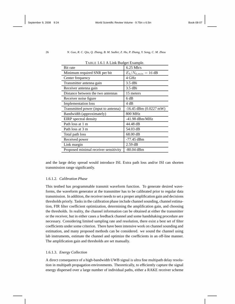
The link budget estimation shown in Table 1.6.1 is based on the following conditions: (1)free space propagation, and (2) OOK modulation with equi-probable transmission of “0”and “1” bits, The transmitted power used here is estimated considering the actual compo-nents used in the transmitter. Spectrum measurement shows that the estimated transmittedPSD is closed to the measured result. The actual transmission range depends on the propa-gation environments. Path loss is much larger in a none-line-of-sight (NLOS) environment
September 9, 2008 9:24 World Scientific Review Volume - 9.75in x 6.5in Book-08-07
26 N. Guo, R. C. Qiu, Q. Zhang, B. M. Sadler, Z. Hu, P. Zhang, Y. Song, C. M. Zhou
TABLE 1.6.1 A Link Budget Example.Bit rate 6.25 Mb/sMinimum required SNR per bit Eb/N0,min = 16 dBCenter frequency 4 GHzTransmitter antenna gain 3.5 dBiReceiver antenna gain 3.5 dBiDistance between the two antennas 15 metersReceiver noise figure 6 dBImplementation loss 4 dBTransmitted power (input to antenna) -16.45 dBm (0.0227 mW)Bandwidth (approximately) 800 MHzEIRP spectral density -41.98 dBm/MHzPath loss at 1 m 44.48 dBPath loss at 3 m 54.03 dBTotal path loss 68.00 dBReceived power -77.45 dBmLink margin 2.59 dBProposed minimal receiver sensitivity -80.04 dBm
and the large delay spread would introduce ISI. Extra path loss and/or ISI can shortentransmission range significantly.
1.6.1.2. Calibration Phase
This testbed has programmable transmit waveform function. To generate desired wave-forms, the waveform generator at the transmitter has to be calibrated prior to regular datatransmission. In addition, the receiver needs to set a proper amplification gain and decisionsthresholds priorly. Tasks in the calibration phase include channel sounding, channel estima-tion, FIR filter coefficient optimization, determining the amplification gain, and choosingthe thresholds. In reality, the channel information can be obtained at either the transmitteror the receiver, but in either cases a feedback channel and some handshaking procedure arenecessary. Considering limited sampling rate and resolution, there exist a best set of filtercoefficients under some criterion. There have been intensive work on channel sounding andestimation, and many proposed methods can be considered. we sound the channel usinglab instruments, estimate the channel and optimize the coefficients in an off-line manner.The amplification gain and thresholds are set manually.
1.6.1.3. Energy Collection
A direct consequence of a high-bandwidth UWB signal is ultra fine multipath delay resolu-tion in multipath propagation environments. Theoretically, to efficiently capture the signalenergy dispersed over a large number of individual paths, either a RAKE receiver scheme
September 9, 2008 9:24 World Scientific Review Volume - 9.75in x 6.5in Book-08-07
Time Reversal for Ultra-wideband Communications: Architecture and Test-bed 27
or an OFDM scheme can provide high performance, given perfect synchronization andchannel estimation. Realistically, a RAKE receiver with tens of fingers is infeasible, andboth schemes mentioned above are financially improper for low-cost low-data-rate appli-cations. There is a huge potential market for these lower-end applications, such as sensornetworks. In response to this need, several suboptimal receiver schemes, including TRand energy detection using a square law detector, have regained popularity in the UWBcommunity. Although both TR and energy detection suffer from performance penalty, theyhave no need for sophisticated channel estimation and precise synchronization, which sig-nificantly reduces receiver complexity and cost. OOK modulation and energy detection isindeed a reasonable combination. Received signal energy can be captured easily using asquare law or diode detector followed by an integrator, and OOK works fine if the datasymbol boundary is roughly known and inter-symbol-interference (ISI) is negligible. Pulseposition modulation (PPM) is another popular modulation for pulse based wide band sys-tems, and high order PPM or called M-ary PPM is promising to work with channel codingto achieve wide range of scalability.
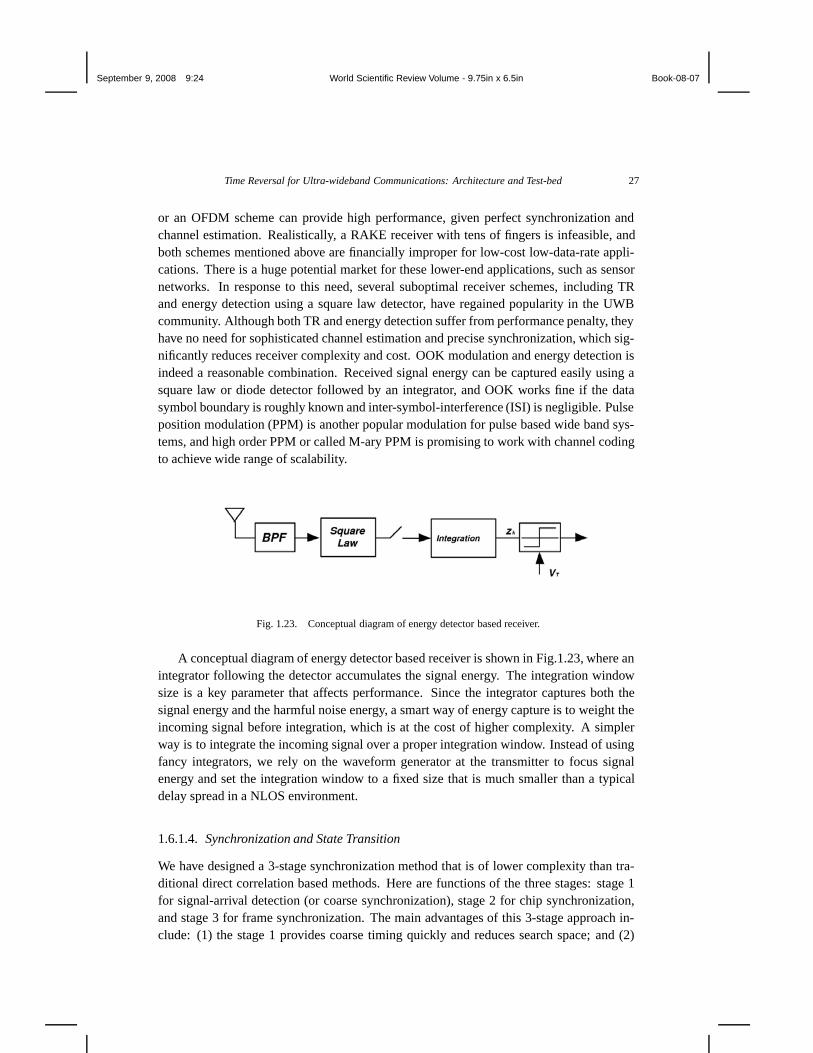
Fig. 1.23. Conceptual diagram of energy detector based receiver.
A conceptual diagram of energy detector based receiver is shown in Fig.1.23, where anintegrator following the detector accumulates the signal energy. The integration windowsize is a key parameter that affects performance. Since the integrator captures both thesignal energy and the harmful noise energy, a smart way of energy capture is to weight theincoming signal before integration, which is at the cost of higher complexity. A simplerway is to integrate the incoming signal over a proper integration window. Instead of usingfancy integrators, we rely on the waveform generator at the transmitter to focus signalenergy and set the integration window to a fixed size that is much smaller than a typicaldelay spread in a NLOS environment.
1.6.1.4. Synchronization and State Transition
We have designed a 3-stage synchronization method that is of lower complexity than tra-ditional direct correlation based methods. Here are functions of the three stages: stage 1for signal-arrival detection (or coarse synchronization), stage 2 for chip synchronization,and stage 3 for frame synchronization. The main advantages of this 3-stage approach in-clude: (1) the stage 1 provides coarse timing quickly and reduces search space; and (2)

September 9, 2008 9:24 World Scientific Review Volume - 9.75in x 6.5in Book-08-07
28 N. Guo, R. C. Qiu, Q. Zhang, B. M. Sadler, Z. Hu, P. Zhang, Y. Song, C. M. Zhou
State 10Data Trans.
State 00Idle
State 01Fine Sync.
Data TransmissionCompletion
SymbolSynchronization
Signal arrival
Synchronization failure
Fig. 1.24. State transition diagram
hard decision is made after stage 2, so that the stage 3 deals with mono-bit sequence, re-sulting in less computation and lower complexity. To shorted the overall synchronizationtime further, parallel chip level processing is employed at the cost of more FPGA resourcesoccupation.
The receiver has three working state and the state transition diagram is given inFig.1.24. Starting with the idle state, if the receiver detects “Signal arrival”, the systemgoes to the fine synchronization state; if synchronization succeeds, the system enters intothe data transmission state, demodulates the data and goes back to the original idle stateafter demodulation. On the other hand, if synchronization failed, the system returns backto the idle state. These state transitions are executed by the finite state machine (FSM)implemented in FPGA.
1.6.2. Implementation
1.6.2.1. Transmitter
Design of Waveform GeneratorA symbol waveform can include multiple pulses to reduce peak power while keeping
enough symbol energy (in this design a symbol contains one data bit). Scrambling codingis necessary to remove DC component and reduce the spectral spikes in the modulatedsignal. In typical indoor environments, delay spread is in the order of tens of nanoseconds,and inter-pulse-interference (IPI) is inevitable as the pulse repetition rate reaches the levelof tens of MHz. A waveform generator is placed at the transmitter to focus the receivedsignal in time and reduce the ISI impact. OOK and PPM are two modulation schemes thatare suitable for non-coherent detection. For higher data rates, a 2-PPM symbol duration hasto be double of an OOK symbol duration to avoid IPI. However, finding a proper thresholdfor OOK demodulation at unknow level of background noise is challenging, but thresholdselection is not necessary for 2-PPM scheme if using differential energy detection.

September 9, 2008 9:24 World Scientific Review Volume - 9.75in x 6.5in Book-08-07
Time Reversal for Ultra-wideband Communications: Architecture and Test-bed 29
Time reversal waveforms have been used to test the system and verify the performance.In a time reversal system, the transmit chip waveform is the time-reversed version of theCIR, which is environment dependent. The waveform generator in the transmitter has tobe programmable to match the instant CIR. Studies have shown that the received signalconcentrates a large percentage of the total energy in a short period of time, enabling theuse of some simple receiver that have little toleration to IPI and ISI
In the transmitter, the baseband waveform generator consists of a pre-filter moduleimplemented in Xilinx Virtex-5 FPGA, a DAC supporting Gsps sampling rate, and thecorresponding connection buses. The pre-filter is a pair of FIR filters with programmablecoefficients able to quadrature sequences.
On the market there are not many DAC and ADC products supporting Gsps samplingrates. Top concerns in selecting them include multiplexing or demultiplexing features, re-configurability and dual-channel. The DAC chip used in the testbed supports dual-channel,14-bit resolution, and sampling clock rate up to 1.0 Gsps. It also features 2:1 (or 28:14)multiplexing, waveform memories, low voltage differential signal (LVDS) interface andconfigurability. Although the high speed digital interface standard LVDS has been usedin the transmitter, the connection between the FPGA and the DAC is actually a bottleneckthat limits the speed. This fact suggests that to increase the speed further, higher ratio mul-tiplexing, shorter connection and maybe some other efforts have to be considered.
Quadture Modulator400 MHz - 4 GHz.
4.0 GHz Center FreqSPI control
Local Oscillator
PA
2 - 8GHz35dB gain
3.1-10 GHZ3.5dBi gain at 4.0 GHz
Antenna
I
Q
Fig. 1.25. The diagram of transmitter RF front-ends
Transmitter RF Front-EndWe mainly rely on off-the-shelf products for RF front-ends in the transmitter. The
transmitter RF front-ends is illustrated in Fig.1.25. The baseband signal from the DACis up-converted to a bandpass signal by the modulator, and after passing through the thepower amplifier, finally the amplified bandpass signal radiates from the antenna.
Reconfigurability and wide frequency range are preferred for the local oscillator (LO).A quadrature type of modulator (or up-converter) is needed to handle complex signals.Baseband bandwidth and input LO frequency range of a modulator (or up-converter) are

September 9, 2008 9:24 World Scientific Review Volume - 9.75in x 6.5in Book-08-07
30 N. Guo, R. C. Qiu, Q. Zhang, B. M. Sadler, Z. Hu, P. Zhang, Y. Song, C. M. Zhou
particularly important to generate wide-band signals. The power amplifier has to be of widebandwidth and there are many choices. A variable attenuator may be used with the poweramplifier in order not to break the FCC emission power ruling.
One common issue in RF implementation is carrier leakage rejection. Although themodulator has very good carrier isolation (say, -37 dBm), there are some other paths thatthe carrier can pass to the output port. Also, unbalanced bias between the two differen-tial input ends of a modulator (or up-converter) makes carrier contribution at the output.Conventional RF decoupling techniques can reduce carrier leakage. In addition, a narrowband notch filer at the carrier frequency may be employed to suppress the output carrierfrequency.
Other Processes
Begin
Reset/ConfigurationKey?
Stop All Process
FPGA Initialization
Configure SystemMode Registers
Configure Local Oscillator
Configure DAC
Fig. 1.26. System control flow for the transmitter.
System ControlAll system control tasks are taken cared by the FPGAs. Configuring some devices
such as DAC and local oscillator (LO) is part of system control. The serial peripheralinterface (SPI) bus is a simple and flexible interface standard that allows one master deviceto communicate with one or multiple slave devices, and it can support data rates up totens of Mbps. In the transmitter, the LO is connected to the FPGA via an SPI bus withthe FPGA serving as the SPI master and the LO as the SPI slave. It shows that SPI bus

September 9, 2008 9:24 World Scientific Review Volume - 9.75in x 6.5in Book-08-07
Time Reversal for Ultra-wideband Communications: Architecture and Test-bed 31
protocol is efficient and can increase system’s flexibility. The system control flow chart inthe transmitter side is presented in Fig. 1.26.
1.6.2.2. Receiver
Front-End AmplificationRequirements for receiver front-end amplification include low noise figure (< 4 dB),
enough gain (max. gain > 60 dB) and proper dynamic range (> 30 dB), consideringmedium range indoor communications. A combined amplifier is built by concatenating alow noise amplifier (LNA) module with ultra low noise figure, a variable attenuator and again block.
ADC and Its Interface to FPGAAn 8-bit monolithic bipolar ADC with sampling rate up to 1.5 Gbps has been selected.
The variable sampling rate is achieved by controlling the output frequency of the clocksource. The ADC features an on-chip, selectable 8:16 output demultiplexer. A double-data-rate (DDR) interface implemented in FPGA connects the ADC to the FPGA. Although themaximal resolution is 8 bits, lower resolution can be chosen in signal processing.
In the receiver of the radio testbed, the ADC employs a fully differential 8 bits quantizerand a unique encoding scheme to limit metastable states, with no error exceeding 1 LSBmax. To facilitate a lower rate digital interface, the ADC features an on-chip, selectable8:16 positive-referenced emitter-coupled logic (PECL) compatible output demultiplexerthat reduces the output data rate to one-half the sampling clock rate.
An ADC-FPGA interface has been carefully designed to support a sampling rate of 800Msps in the receiver. A single-data-rate (SDR) interface with a FIFO memory is imple-mented in FPGA to receive data from the ADC.
In designing the high-speed interface between ADC (or DAC) and FPGA, signal in-tegrity has become a critical issue. Many signal integrity problems are electromagneticphenomena in nature. There are two concerns for signal integrity: the timing and the qual-ity of the signal. Signal timing mainly depends on the delay caused by the physical lengthand the material of each segment along a signal propagating path. Signal waveform distor-tions can be caused by reflection, cross talk, and power/ground noise.
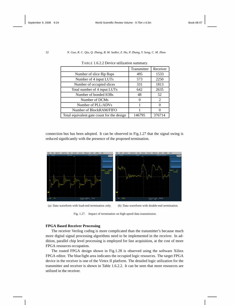
An important parameter is the characteristic impedance Z0 defined as the voltage-to-current ratio at any point along the transmission line. If the far end is terminated withresistance R = Z0 over the entire frequency band, impedance matching is perfect and theforward propagating wave is fully absorbed by the load. On the other hand, an impedancemismatched load would cause reflecting wave traveling back to the source, and it may be re-flected again if the source is impedance mismatched, resulting in rings on top of the originalwaveform. Such ringing has a serious impact on signal integrity, reduces noise/interferencetoleration margins, and even leads to malfunction. A way to avoid reflections and en-sure signal integrity is a proper termination. Most high-speed data interface standards(such as LVDS) require load-end termination for impedance matching but do not requiresource/driver-end termination. For better result, double-end termination at both ends of the
September 9, 2008 9:24 World Scientific Review Volume - 9.75in x 6.5in Book-08-07
32 N. Guo, R. C. Qiu, Q. Zhang, B. M. Sadler, Z. Hu, P. Zhang, Y. Song, C. M. Zhou
TABLE 1.6.2.2 Device utilization summary.
Transmitter ReceiverNumber of slice flip flops 495 1533Number of 4 input LUTs 573 2250
Number of occupied slices 331 1813Total number of 4 input LUTs 642 2635
Number of bonded IOBs 48 52Number of DCMs 0 2
Number of PLL/ADVs 1 0Number of BlockRAM/FIFO 1 0
Total equivalent gate count for the design 146795 376714
connection bus has been adopted. It can be observed in Fig.1.27 that the signal swing isreduced significantly with the presence of the proposed termination.
(a) Data waveform with load-end termination only. (b) Data waveform with double-end termination.
Fig. 1.27. Impact of termination on high-speed data transmission.
FPGA Based Receiver ProcessingThe receiver Verilog coding is more complicated than the transmitter’s because much
more digital signal processing algorithms need to be implemented in the receiver. In ad-dition, parallel chip level processing is employed for fast acquisition, at the cost of moreFPGA resources occupation.
The routed FPGA design shown in Fig.1.28 is observed using the software XilinxFPGA editor. The blue/light area indicates the occupied logic resources. The target FPGAdevice in the receiver is one of the Virtex II platform. The detailed logic utilization for thetransmitter and receiver is shown in Table 1.6.2.2. It can be seen that more resources areutilized in the receiver.

September 9, 2008 9:24 World Scientific Review Volume - 9.75in x 6.5in Book-08-07
Time Reversal for Ultra-wideband Communications: Architecture and Test-bed 33
Fig. 1.28. Routed FPGA design for the receiver.
1.6.3. System Test and Results
The functionalities of the time reversal testbed and the temporal focusing property can beverified through experiment. A packet with a given data payload is transmitted repeatedly.The transmit and receive antennas are placed in a non-line-of-sight (NLOS) manner. Atthe receiver, if the demodulated sequence matches to the transmitted sequence, then we cansay the system is working properly. Moreover, waveform level temporal focusing can beobserved at the receiver using an oscilloscope.
1.6.3.1. Preparing the Experiment
In addition to the testbed, below is a list of instruments used in the experiment, and each ofthem must be calibrated well before use.
• Vector Network Analyzer (VNA)• Spectrum Analyzer (SA)• Logic Analyzer (LA)• Digital Phosphor Oscilloscope (DPO)
Time reversal template (coefficients of the FIR pre-filter) preparation is a major task inthe experiment. Specifically, the CIR has to be estimated and converted into a fixed-pointsequence, and then load the sequence to the coefficient memory. In a real system, we needto implement channel sounding and estimation functions to provide the transmitter with the

September 9, 2008 9:24 World Scientific Review Volume - 9.75in x 6.5in Book-08-07
34 N. Guo, R. C. Qiu, Q. Zhang, B. M. Sadler, Z. Hu, P. Zhang, Y. Song, C. M. Zhou
(a) Office layout.
(b) Compartment A. (c) Compartment B.
Fig. 1.29. Office environment.
template. However, for the sake of time reversal functionality verification, with help of labinstruments, we can obtain the template off line and load it to the memory in advance.
1.6.3.2. Environment and System Setup
According to time reversal theory, the environment should be as complex as possible,so that rich multipath can be obtained. According to this philosophy, our system test isperformed in a typical non-line-of-sight (NLOS), three-compartment office environment(Fig.1.29). Transmit antenna and receive antenna are located in compartment A and com-partment B, as can be seen from Fig.1.29. There are wood and metal shelves, desks andchairs, computers and electronic equipments in the office. These furnitures reflect signalsand cause multipath propagation. These antennas are omni-directional and the line-of-sight
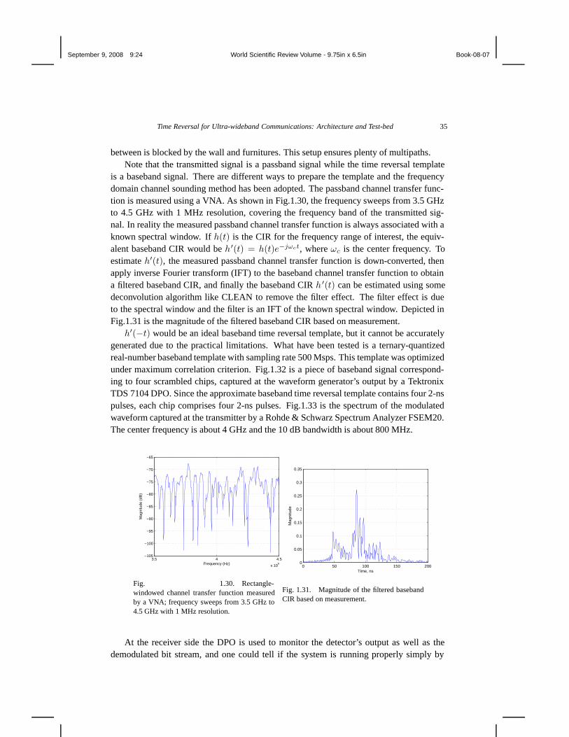
September 9, 2008 9:24 World Scientific Review Volume - 9.75in x 6.5in Book-08-07
Time Reversal for Ultra-wideband Communications: Architecture and Test-bed 35
between is blocked by the wall and furnitures. This setup ensures plenty of multipaths.Note that the transmitted signal is a passband signal while the time reversal template
is a baseband signal. There are different ways to prepare the template and the frequencydomain channel sounding method has been adopted. The passband channel transfer func-tion is measured using a VNA. As shown in Fig.1.30, the frequency sweeps from 3.5 GHzto 4.5 GHz with 1 MHz resolution, covering the frequency band of the transmitted sig-nal. In reality the measured passband channel transfer function is always associated with aknown spectral window. If h(t) is the CIR for the frequency range of interest, the equiv-alent baseband CIR would be h′(t) = h(t)e−jωct, where ωc is the center frequency. Toestimate h′(t), the measured passband channel transfer function is down-converted, thenapply inverse Fourier transform (IFT) to the baseband channel transfer function to obtaina filtered baseband CIR, and finally the baseband CIR h ′(t) can be estimated using somedeconvolution algorithm like CLEAN to remove the filter effect. The filter effect is dueto the spectral window and the filter is an IFT of the known spectral window. Depicted inFig.1.31 is the magnitude of the filtered baseband CIR based on measurement.
h′(−t) would be an ideal baseband time reversal template, but it cannot be accuratelygenerated due to the practical limitations. What have been tested is a ternary-quantizedreal-number baseband template with sampling rate 500 Msps. This template was optimizedunder maximum correlation criterion. Fig.1.32 is a piece of baseband signal correspond-ing to four scrambled chips, captured at the waveform generator’s output by a TektronixTDS 7104 DPO. Since the approximate baseband time reversal template contains four 2-nspulses, each chip comprises four 2-ns pulses. Fig.1.33 is the spectrum of the modulatedwaveform captured at the transmitter by a Rohde & Schwarz Spectrum Analyzer FSEM20.The center frequency is about 4 GHz and the 10 dB bandwidth is about 800 MHz.
3.5 4 4.5
x 109
−105
−100
−95
−90
−85
−80
−75
−70
−65
Frequency (Hz)
Mag
nitu
de (
dB)
Fig. 1.30. Rectangle-windowed channel transfer function measuredby a VNA; frequency sweeps from 3.5 GHz to4.5 GHz with 1 MHz resolution.
0 50 100 150 2000
0.05
0.1
0.15
0.2
0.25
0.3
0.35
Time, ns
Mag
nitu
de
Fig. 1.31. Magnitude of the filtered basebandCIR based on measurement.
At the receiver side the DPO is used to monitor the detector’s output as well as thedemodulated bit stream, and one could tell if the system is running properly simply by

September 9, 2008 9:24 World Scientific Review Volume - 9.75in x 6.5in Book-08-07
36 N. Guo, R. C. Qiu, Q. Zhang, B. M. Sadler, Z. Hu, P. Zhang, Y. Song, C. M. Zhou
Fig. 1.32. Baseband time reversal waveformafter scrambling.
3 3.5 4 4.5 5−70
−65
−60
−55
−50
−45
−40
−35
−30
GHz
dBm
Fig. 1.33. Spectrum of time reversal wave-form after modulation.
observing the demodulated bit stream.
1.6.3.3. Experimental Results
During the first demonstration,59 a given pseudo-random (PN) sequence was transmittedperiodically at bit rate 6.25 Mbps. Fig.1.34 shows the system test observations. The toptrace is the transmitted baseband waveform, the middle trace is the detector output, and thebottom trace is the demodulated bit stream. In order to observe the signals more conve-niently, the scales for top trace, middle trace and bottom trace are set to 50 mV/div, 100mV/div and 5 V/div, respectively. The top trace is simply a zoom-out version of Fig.1.32.Although there are some interferences observed on both the middle and the bottom trace,distinguishable peaks can be seen on the middle trace and the PN sequence can be readclearly from the bottom trace.
Fig. 1.34. System test result.Fig. 1.35. Temporal focusing property of timereversal.
A close-up of the middle trace is shown in Fig.1.35.The top trace is the baseband trans-

September 9, 2008 9:24 World Scientific Review Volume - 9.75in x 6.5in Book-08-07
Time Reversal for Ultra-wideband Communications: Architecture and Test-bed 37
mitted waveform, the middle trace is the received waveform at the detector’s output, andthe bottom trace is a data clock running at 6.25 MHz, the same as the data rate. Tempo-ral focusing property can be observed from the middle trace. Four pulses are transmittedin each chip period, while in the detector’s output there is only one strong peak in eachchip period, because the four separated pulses arrived at the receiver at the same time aftertraveling through different paths and add up constructively. Although the mainlobe is dom-inant, some sidelobes are noticeable, suggesting that either the waveform generator needsto be refined, or other signal processing techniques should be combined.
1.7. Conclusions
High-resolution of ultr-wideband pulses leads to rich multipath. Fading is secondary forUWB systems. The channel is reciprocal for a long period of time—much longer than itsnarrow-band counterpart. The central idea presented in this chapter is to take advantage ofthis reciprocity to focus multipath pulses at the receiver—through waveform preprocessingat the transmitter. This scheme allows to use simple receivers and enables spatial divisionmultiplexing access (SDMA) and additional physical layer security.
The principles and design philosophy, along with an example of experimental timereversal test-bed, have been introduced. Waveform level preprocessing with fractionalsymbol sampling is a general pre-filtering process at the transmitter for different optimumcriteria. Some traditional receiver based processing functions can be taken care of by pre-processing, so that suboptimal reception schemes such as transmitter-reference and squarelaw detector can be used without significantly sacrificing overall performance. Preprocess-ing paired with simple receivers are especially attractive to wireless sensor network (WSN)applications where strict constraints are posed. In addition to performance enhancement,preprocessing also features SDMA or physical layer security enhancement without con-suming extra radio resources. Knowing the characteristics of scattering channels is the keyto best design a preprocessing system, which motivates our experiment based investigationon a few realistic radio channels. The concept of preprocessing plus simple receivers hasbeen demonstrated using a time reversal radio test-bed working in microwave band in theindoor environment.
For future work, security and anti-jamming capabilities are enhanced by channel reci-procity. This line of thought needs further research. The availability of five GHz digital-to-analog converter (DAC) makes this direction feasible. Compressed sensing provides arevolutionary approach to handle waveforms of much wider bandwidth. 55 Transient UWBpulses are compressible .61 Information theory can be used for secrecy. Ultra-widebandsensing and networking can be integrated into one radio. This radio must have the abil-ity to access spectrum dynamically—cognitive radio and cognitive radar. 60 As a result,wideband (e.g. multi-GHz) spectrum sensing is needed—but an open problem.
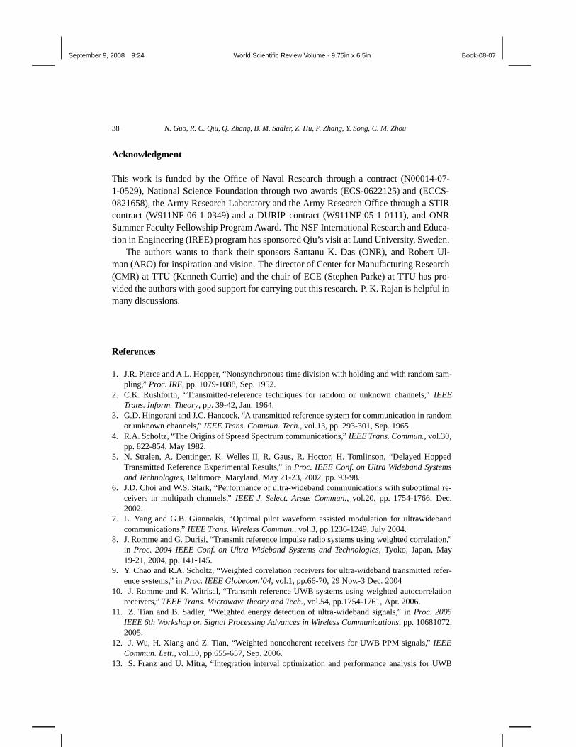
September 9, 2008 9:24 World Scientific Review Volume - 9.75in x 6.5in Book-08-07
38 N. Guo, R. C. Qiu, Q. Zhang, B. M. Sadler, Z. Hu, P. Zhang, Y. Song, C. M. Zhou
Acknowledgment
This work is funded by the Office of Naval Research through a contract (N00014-07-1-0529), National Science Foundation through two awards (ECS-0622125) and (ECCS-0821658), the Army Research Laboratory and the Army Research Office through a STIRcontract (W911NF-06-1-0349) and a DURIP contract (W911NF-05-1-0111), and ONRSummer Faculty Fellowship Program Award. The NSF International Research and Educa-tion in Engineering (IREE) program has sponsored Qiu’s visit at Lund University, Sweden.
The authors wants to thank their sponsors Santanu K. Das (ONR), and Robert Ul-man (ARO) for inspiration and vision. The director of Center for Manufacturing Research(CMR) at TTU (Kenneth Currie) and the chair of ECE (Stephen Parke) at TTU has pro-vided the authors with good support for carrying out this research. P. K. Rajan is helpful inmany discussions.
References
1. J.R. Pierce and A.L. Hopper, “Nonsynchronous time division with holding and with random sam-pling,” Proc. IRE, pp. 1079-1088, Sep. 1952.
2. C.K. Rushforth, “Transmitted-reference techniques for random or unknown channels,” IEEETrans. Inform. Theory, pp. 39-42, Jan. 1964.
3. G.D. Hingorani and J.C. Hancock, “A transmitted reference system for communication in randomor unknown channels,” IEEE Trans. Commun. Tech., vol.13, pp. 293-301, Sep. 1965.
4. R.A. Scholtz, “The Origins of Spread Spectrum communications,” IEEE Trans. Commun., vol.30,pp. 822-854, May 1982.
5. N. Stralen, A. Dentinger, K. Welles II, R. Gaus, R. Hoctor, H. Tomlinson, “Delayed HoppedTransmitted Reference Experimental Results,” in Proc. IEEE Conf. on Ultra Wideband Systemsand Technologies, Baltimore, Maryland, May 21-23, 2002, pp. 93-98.
6. J.D. Choi and W.S. Stark, “Performance of ultra-wideband communications with suboptimal re-ceivers in multipath channels,” IEEE J. Select. Areas Commun., vol.20, pp. 1754-1766, Dec.2002.
7. L. Yang and G.B. Giannakis, “Optimal pilot waveform assisted modulation for ultrawidebandcommunications,” IEEE Trans. Wireless Commun., vol.3, pp.1236-1249, July 2004.
8. J. Romme and G. Durisi, “Transmit reference impulse radio systems using weighted correlation,”in Proc. 2004 IEEE Conf. on Ultra Wideband Systems and Technologies, Tyoko, Japan, May19-21, 2004, pp. 141-145.
9. Y. Chao and R.A. Scholtz, “Weighted correlation receivers for ultra-wideband transmitted refer-ence systems,” in Proc. IEEE Globecom’04, vol.1, pp.66-70, 29 Nov.-3 Dec. 2004
10. J. Romme and K. Witrisal, “Transmit reference UWB systems using weighted autocorrelationreceivers,” TEEE Trans. Microwave theory and Tech., vol.54, pp.1754-1761, Apr. 2006.
11. Z. Tian and B. Sadler, “Weighted energy detection of ultra-wideband signals,” in Proc. 2005IEEE 6th Workshop on Signal Processing Advances in Wireless Communications, pp. 10681072,2005.
12. J. Wu, H. Xiang and Z. Tian, “Weighted noncoherent receivers for UWB PPM signals,” IEEECommun. Lett., vol.10, pp.655-657, Sep. 2006.
13. S. Franz and U. Mitra, “Integration interval optimization and performance analysis for UWB

September 9, 2008 9:24 World Scientific Review Volume - 9.75in x 6.5in Book-08-07
Time Reversal for Ultra-wideband Communications: Architecture and Test-bed 39
transmitted reference systems,” in Proc. 2004 IEEE Conf. on Ultra Wideband Systems and Tech-nologies, Tyoko, Japan, May 19-21, 2004, pp. 26-30.
14. Y.-L. Chao, “Optimal integration time for UWB transmitted reference correlation receivers,”in Proc. 38th Asilomar conf. on Signals, Systems and Computers, vol.1, pp.647-651, 7-10 Nov.2004.
15. D.L. Goeckel and Q. Zhang, “Slightly frequency-shifted reference ultra-wideband (UWB) radio:TR-UWB without the delay element,” in Proc. IEEE Milcom’05, vol.5, pp.3029-3035, 17-20 Oct.2005.
16. D.L. Goeckel, J. Mehlman and J. Burkhart, “A class of ultra wideband (UWB) systems withsimple receivers,” in Proc. IEEE Milcom’07, vol.5, pp.1-7, Orlando, FL, 29-31 Oct. 2007.
17. H. Liu, A.F. Molisch, S. Zhao, D. Goeckel and P. Orlikt, “Hybrid coherent and frequency-shifted-reference ultrawideband radio,” in Proc. IEEE Globecom’07, pp.4106-4111, Washington,DC, 26-30 Nov. 2007.
18. M.K. Simon, S.M. Hinedi and W.C. Lindsey, Digital Communication Techniques - Signal Designand Detection, Englewood Cliffs, NJ: Prentice Hall, 1994.
19. M. Ho, V. Somayazulu, J. Foerster, and S. Roy, “A differential detector for an ultra-widebandcommunications system,” in Proc. 55th IEEE Veh. Tech. Conf., vol.4, May 2002, pp.1896-1900.
20. Y. Chao and R.A. Scholtz, “Optimal and suboptimal receivers for Ultra-wideband transmittedreference systems,” in Proc. IEEE Globecom’03, pp.759-763, Dec. 2003.
21. S. Zhao, H. Liu and Z. Tian, “A decision feedback autocorrelation receiver for pulsed ultra-wideband systems,” in Proc. IEEE Rawcon’04, Sep. 2004.
22. Y. Souilmi and R. Knopp, “On the achievable rates of ultra-wideband PPM with non-coherentdetection in multipath environments,” in Proc. IEEE ICC’03, vol.5, May 11-15, 2003, pp. 3530-3534.
23. M. Weisenhorn and W. Hirt, “Robust noncoherent receiver exploiting UWB channel properties,”in Proc. IEEE UWBST’04, Kyoto, Japan, May 19-21, 2004, pp. 156-160.
24. S. Paquelet, L Aubert and B. Uguen, “An impulse radio asynchronous transceiver for high datarates,” in Proc. IEEE UWBST’04, Kyoto, Japan, May 19-21, 2004, pp.1-5.IEEE Commun. Lett., vol.10, pp.655-657, Sep. 2006.
25. N. Guo, J. Zhang, R. Qiu and S. Mo, “UWB MISO time reversal with energy detector receiverover ISI channels,” in Proc. IEEE CCNC’07, Las Vegas, NV, Jan. 11-13, 2007.
26. F. Edbauer, “Bit error rate of binary and quaternary DPSK signals with multiple differentialfeedback detection,” IEEE Trans. Commun., vol.40, pp. 457-460, March 1992.
27. N. Guo and R.C. Qiu, “Improved autocorrelation demodulation receivers based on multiple-symbol detection for UWB communications,” IEEE Trans. Wireless Commun., vol.5, pp.2026-2031, Aug. 2006.
28. V. Lottici and Z. Tian, “Multiple symbol differential detection for UWB communications,” IEEETrans. Wireless Commun., vol.7, pp.1656-1666, May. 2008.
29. A. V. Oppenheim and R. W. Schafer, Discrete-Time Signal Processing, 2nd ed. Upper SaddleRiver, New Jersey: Prentice Hall Inc., 1999.
30. K. Witrisal, G. Leus, M. Pausini and C. Krall, “Equivalent system model and equalization ofdifferential impulse radio UWB systems,” IEEE J. Select. Areas Commun., vol.23, pp.1851-1862,Sep. 2005.
31. M. Pausini, G.J.M. Janssen and K. Witrisal, “Performance enhancement of differential UWBautocorrelation receivers under ISI,” IEEE J. Select. Areas Commun., vol.24, pp.815-821, Apr.2006.
32. J. Yang and S. Roy, “Joint transmitter-receiver optimization for multi-input multi-output systemswith decision feedback,” IEEE Trans. Inf. Theory, vol.40, pp.1334-1347, Sep. 1994.
33. J. Yang and S. Roy, “On joint transmitter and receiver optimization for multiple-input-multiple-output (MIMO) transmission systems,” IEEE Trans. Commun., vol.42, pp.3221-3231, Dec. 1994.
September 9, 2008 9:24 World Scientific Review Volume - 9.75in x 6.5in Book-08-07
40 N. Guo, R. C. Qiu, Q. Zhang, B. M. Sadler, Z. Hu, P. Zhang, Y. Song, C. M. Zhou
34. H. Sampath, P. Stoica and A. Paulraj, “Generalized linear precoder and decoder design forMIMO channels using the weighted MMSE criterion,” IEEE Trans. Commun., vol.49, pp.2198-2206, Dec. 2001.
35. Scaglione, A.; Stoica, P.; Barbarossa, S.; Giannakis, G.B.; Sampath, H.;“Optimal designs forspace-time linear precoders and decoders,” IEEE Trans. Signal Proc. [see also IEEE Trans.Acoustics, Speech, and Signal Proce.], vol.50, pp.1051-1064, May 2002.
36. D.P. Palomar and M.A. Lagunas, “Joint transmit-receive space-time equalization in spatiallycorrelated MIMO channels: a beamforming approach,” IEEE J. Select. Areas Commun., vol.21,pp.730-743, June 2003.
37. D.P. Palomar, M.A. Lagunas and J.M. Cioffi, “Optimum linear joint transmit-receive process-ing for MIMO channels with QoS constraints,” IEEE Trans. Signal Proc. [see also IEEE Trans.Acoustics, Speech, and Signal Proce.], vol.52, pp.1179-1197, May 2004.
38. J.W. Matthews, “Eigenvalues and troposcatter multipath analysis,” IEEE J. Select. Areas Com-mun., vol.10, pp.497-505, Apr. 1992.
39. H.L. Van Trees, Detection, Estimation, and Modulation Theory, Part I, New York: Wily, 1968.40. M.R. Bell, “Information theory and radar waveform design,” IEEE Trans. Inf. Theory, vol.39,
pp.1578-1597, Sep. 1993.41. M. Fink, “Time reversal of ultrasonic fields–Part I: Basic principles,” IEEE Trans. Ultrason.,
Ferroelec. Frequency Control, vol.39, no.5, pp.555-566, Sep. 1992.42. T. Strohmer, M. Emami, J. Hansen, G. Pananicolaou and A.J. Paulraj, “Application of time-
reversal with MMSE equalizer to UWB communications,” in Proc. Globecom’04, Dallas, TX,Dec. 2004, pp.3123-3127.
43. P. Kyristi, G.G. Pananicolaou, P. Eggers and A. Oprea, “MISO time reversal and delay spreadcompression for FWA channels at 5 GHz,” IEEE Ant. and Wireless Prop. Lett., vol.3, pp.96-99,2004.
44. H.T. Nguyen, J.B. Andersen and G.F. Pedersen, “The potential use of time reversal techniquesin multiple element antenna systems,” IEEE Com. Lett., vol.9, pp.40-42, Jan. 2005.
45. H.T. Nguyen, J.B. Andersen, G.F. Pedersen, P. Kyritsi and P.C.F. Eggers, “Time reversal inwireless communications: a measurement-based investigation,” IEEE Trans. Wireless Commun.,vol.5, pp.2242-2252, Aug. 2006.
46. H.T. Nguyen, I.Z. Kovcs and P.C.F. Eggers, “A time reversal transmission approach for multiuserUWB communications,” IEEE Trans. Ant. Prop., vol.54, pp.3216-3224, Nov. 2006.
47. A.E. Akogun, R.C. Qiu and N. Guo, “Demonstrating time reversal in ultra-wideband commu-nications using time domain measurements,” in Proc. 51st International Instrumentation Sympo-sium, Knoxville, TN, May 8-12, 2005.
48. N. Guo, R.C. Qiu and B.M. Sadler, “An Ultra-wideband autocorrelation demodulation schemewith low-complexity time reversal enhancement,” in Proc. IEEE MILCOM’05, vol.5, pp.3066-3072, Atlantic City, NJ, 17-20 Oct., 2005.
49. R.C. Qiu, C. Zhou, N. Guo, and J.Q. Zhang, “Time reversal with MISO for ultra-widebandcommunications: experimental results,” IEEE Antenna and Wireless Propagation Letters, vol.5,pp.269-273, Dec. 2006.
50. N. Guo, J. Zhang and R. Qiu, “UWB MISO Time Reversal With Energy Detector Receiver OverISI Channels,” in Proc. IEEE CCNC’07.
51. N. Guo, B.M. Sadler and R.C. Qiu, “Reduced-complexity UWB time reversal techniques andexperimental results,” IEEE Trans. Wireless Commun., vol.6, pp.4221-4226, Dec. 2007.
52. R, Ahlswede and I. Csiszar, “Common randomness in information theory and cryptography. I.Secret sharing,” IEEE Trans. Inf. Theory, vol.39, pp.1121-1132, July 1993.
53. R. Wilson, D. Tse and Robert A. Scholtz, “Channel identification: secret sharing using reci-procity in ultrawideband channels,” IEEE Trans. Inf. Forensics and Security, vol.2, pp.364-375,Feb. 2007.

September 9, 2008 9:24 World Scientific Review Volume - 9.75in x 6.5in Book-08-07
Time Reversal for Ultra-wideband Communications: Architecture and Test-bed 41
54. M. Bloch, J. Barros, M.R.D. Rodrigues and S.W. McLaughlin, “Wireless information-theoreticsecurity,” IEEE Trans. Inf. Theory, vol.54, pp.2515-2534, June 2008.
55. R. C. Qiu, Underwater Acoustic Sensor Networks, ch. Physics-Based Channel Models and Fun-damental Limits. Auerbach Publications, Taylor & Francis Group, 2008.
56. Robert G. Gallager, “Information Theory and Reliable Communication,” John Wiley & Sons,Inc., 1968.
57. M. Calderon and R. C. Qiu, “Time Reversal for Ultra-Wideband (UWB) Sensor Networking,”tech. rep., Final Report to Army Research Office, Grant no. W911NF-06-1-0349, 151 pages,TTU, Cookeville, TN, July 2007.
58. R. C. Qiu and et al, “Ultra-Wideband Communications Systems and Testbed,” Final Reportto Army Research Office Grant no. W911NF-05-01-0111 (DURIP), Tennessee Tech University,Cookeville, TN, July 2007. 240 pages.
59. R. C. Qiu and et al, “Time-Reversal Based Range Extension Technique for Ultra-Wideband(UWB) Sensors and Applications in Tactical Communications and Networking,” (Quarterly)Technical Report to Office of Naval Research (ONR) Contract No. N00014-07-1-0529, TennesseeTech University, Cookeville, TN, April 2008. 69 pages.
60. S. Haykin, “Cognitive radar,” IEEE SIGNAL PROCESSING MAGAZINE, pp. 30–40, Jan. 2006.61. R. C. Qiu, Ultra-WidebandWireless Communication: Physical and Information-Theoretical
Limits. Course Reader for ECE 7750 and ECE 7970, Tennessee Technological University,http://iweb.tntech.edu/rqiu, March 2008.
Related Documents