Chapter 1 Subsurface Macro Structure The flow of fluids and transport of species through porous media occur in a macroscopic system with geometric boundaries and internal structure. When the system is subsurface formations of the earth, it is described by the structural geology of the system. Even though the geology presented here will be superficial, it will provide the setting for a more detailed study of the transport processes. Depositional Environments The formations making up the earth’s crust is described by the term “facies”. This is an interpretative description that has many levels. Most everyone is familiar with the meaning of igneous, metamorphic, and sedimentary facies. The sedimentary facies is of most interest with respect to fluid flow. The sedimentary facies is broadly divided into sandy or sandstone facies, shaly facies, and carbonate facies. The sandstone facies can be divided into “deep water facies”, “turbidite facies”, “deltaic facies”, etc. As you can see, the facies is related to the environment in which the sediment was deposited. Figure 1.1 is a representation of the various environments that sediments may be deposited. Fig 1.1 Schematic representation of sedimentary environments (from Bjorlykke, 1989) 1-1

Welcome message from author
This document is posted to help you gain knowledge. Please leave a comment to let me know what you think about it! Share it to your friends and learn new things together.
Transcript

Chapter 1 Subsurface Macro Structure The flow of fluids and transport of species through porous media occur in a macroscopic system with geometric boundaries and internal structure. When the system is subsurface formations of the earth, it is described by the structural geology of the system. Even though the geology presented here will be superficial, it will provide the setting for a more detailed study of the transport processes.
Depositional Environments The formations making up the earth’s crust is described by the term “facies”. This is an interpretative description that has many levels. Most everyone is familiar with the meaning of igneous, metamorphic, and sedimentary facies. The sedimentary facies is of most interest with respect to fluid flow. The sedimentary facies is broadly divided into sandy or sandstone facies, shaly facies, and carbonate facies. The sandstone facies can be divided into “deep water facies”, “turbidite facies”, “deltaic facies”, etc. As you can see, the facies is related to the environment in which the sediment was deposited. Figure 1.1 is a representation of the various environments that sediments may be deposited.
Fig 1.1 Schematic representation of sedimentary environments (from Bjorlykke, 1989)
1-1
Fundamental Mechanism for Grain Size Sorting The most noticeable difference in sandstones is the size of the grains making up the rock. The sorting mechanism in water borne sediments is based on Stoke's Law (for small particles). Consider the balance of forces acting on a spherical particle with radius R settling in a fluid by the action of gravity. There is the buoyancy force and the drag force as a result of its motion. The velocity of settling can be determined be equating these two forces.
3
2
436
29
buoyance
drag
F R
F R v
v R g
gπ ρ
π µ
µ ρ
= ∆
=
= ∆
Thus larger particles settle faster than smaller particles in proportion the square of the particle size.
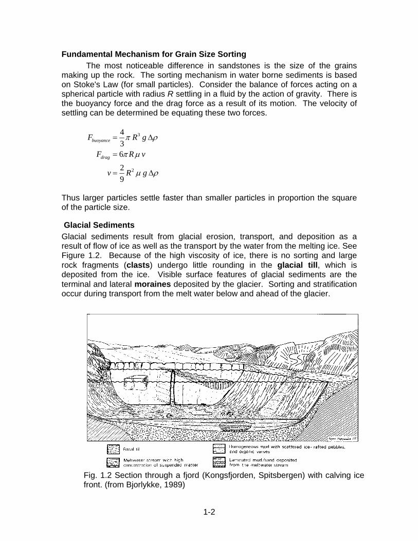
Glacial Sediments Glacial sediments result from glacial erosion, transport, and deposition as a result of flow of ice as well as the transport by the water from the melting ice. See Figure 1.2. Because of the high viscosity of ice, there is no sorting and large rock fragments (clasts) undergo little rounding in the glacial till, which is deposited from the ice. Visible surface features of glacial sediments are the terminal and lateral moraines deposited by the glacier. Sorting and stratification occur during transport from the melt water below and ahead of the glacier.
Fig. 1.2 Section through a fjord (Kongsfjorden, Spitsbergen) with calving ice front. (from Bjorlykke, 1989)
1-2

Alluvial Fans Alluvial fan sediments are deposits of sediments in regions of high relief, generally where streams issue from mountains onto a level plain, see Figure 1.3. The fan starts at the apex, which is the source of sediments from regions of higher relief. Sediment transport from here will tend to follow the steepest slope downward, and the sediments will therefore spread out in a fan. The largest boulders or pebbles will be deposited near the apex. Downslope the fan channels split up into a number of smaller channels. This reduces the velocity of the water flow and the capacity for carrying sediment is lowered. Sediment will therefore become finer-grained downslope, even if there is no reduction in the steepness of the slope.
Fig. 1.3 Schematic representation of an alluvial fan developed along a basement fault. (from Bjorlykke, 1989)
Eolian Deposits Eolian (From Eolus, the God of winds.) deposits are wind blown sand dunes, which commonly occur, in deserts or near the seacoast where there is a lack of vegetation. A common characteristic of eolian deposits is large-scale cross-bedding (large scale cross-stratification) as a result of deposition on the leeward side of sand dunes, see Figure 1.4. The sands are well sorted because of the sifting action of the wind. Thus there will be an absence of clay drapes or silt layers between the cross-bedded layers as in marine deposits.
1-3
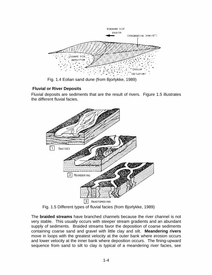
Fig. 1.4 Eolian sand dune (from Bjorlykke, 1989)
Fluvial or River Deposits Fluvial deposits are sediments that are the result of rivers. Figure 1.5 illustrates the different fluvial facies.
Fig. 1.5 Different types of fluvial facies (from Bjorlykke, 1989)
The braided streams have branched channels because the river channel is not very stable. This usually occurs with steeper stream gradients and an abundant supply of sediments. Braided streams favor the deposition of coarse sediments containing coarse sand and gravel with little clay and silt. Meandering rivers move in loops with the greatest velocity at the outer bank where erosion occurs and lower velocity at the inner bank where deposition occurs. The fining-upward sequence from sand to silt to clay is typical of a meandering river facies, see
1-4

Figure 1.6. This sequence is the result of the water velocity decreasing as the river over a given spot migrates from the outer bank to the inner bank. When the spot is no longer in the river but is in the flood plain, then only clay and silt from nearly stagnant water will be deposited. The anastomosing stream is defined as a branching, interlacing steam having a netlike appearance. The facies illustrated in Figure 1.5 is typical of bayous and slough in regions of very low
stream gradient and with subsidence as along the Gulf Coast.
Fig. 1.6 Schematic representation of a fining-upward sequence deposited in a meandering river (from Bjorlykke, 1989)
Delta Sedimentation Deltas form where rivers carrying a large supply of sediment empty into a sea coast where it can not be transported away as fast as it is deposited. Thus it is in the transition region between the fluvial and marine environments. The Mississippi River delta is a good example. Figure 1.7 illustrates the delta types based on the relative dominance of river and marine processes. The Important components of a delta sediment are the channel, fringe (or delta plain), and delta front facies which are illustrated in cross-section in Figure 1.8. The lithology (physical description of rocks; syn.: petrography) of these facies are illustrated in Figure 1.9.
1-5

Fig. 1.7 Classification of delta types based on relative amount of dominance by river processes (constructive) and marine processes (destructive). [(Fisher et al. 1974), in Bjorlykke 1989]
Fig. 1.8 Fluvial channel sand in clay-rich delta. (Bjorlykke 1989)
1-6
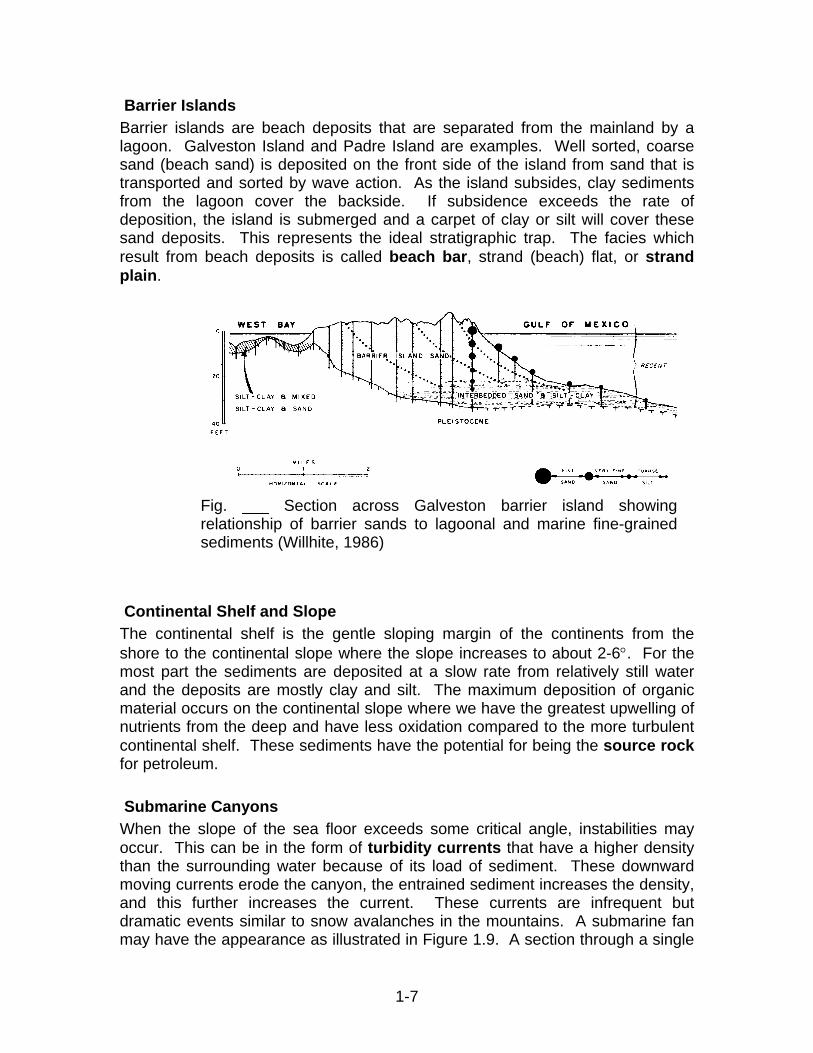
Barrier Islands Barrier islands are beach deposits that are separated from the mainland by a lagoon. Galveston Island and Padre Island are examples. Well sorted, coarse sand (beach sand) is deposited on the front side of the island from sand that is transported and sorted by wave action. As the island subsides, clay sediments from the lagoon cover the backside. If subsidence exceeds the rate of deposition, the island is submerged and a carpet of clay or silt will cover these sand deposits. This represents the ideal stratigraphic trap. The facies which result from beach deposits is called beach bar, strand (beach) flat, or strand plain.
Fig. ___ Section across Galveston barrier island showing relationship of barrier sands to lagoonal and marine fine-grained sediments (Willhite, 1986)
Continental Shelf and Slope The continental shelf is the gentle sloping margin of the continents from the shore to the continental slope where the slope increases to about 2-6°. For the most part the sediments are deposited at a slow rate from relatively still water and the deposits are mostly clay and silt. The maximum deposition of organic material occurs on the continental slope where we have the greatest upwelling of nutrients from the deep and have less oxidation compared to the more turbulent continental shelf. These sediments have the potential for being the source rock for petroleum.
Submarine Canyons When the slope of the sea floor exceeds some critical angle, instabilities may occur. This can be in the form of turbidity currents that have a higher density than the surrounding water because of its load of sediment. These downward moving currents erode the canyon, the entrained sediment increases the density, and this further increases the current. These currents are infrequent but dramatic events similar to snow avalanches in the mountains. A submarine fan may have the appearance as illustrated in Figure 1.9. A section through a single
1-7

sand unit is shown on the left of Figure 1.20 and three sand units on the right. The base of the sand will contain the coarse sediment that is the first to settle from the turbidite current. The grain size will become fine upward because the fine material will be the last to settle. Clay layers are deposited between turbidity current events. A vertical sequence through a submarine fan may appear as in Figure 1.21. Each sand unit corresponds to the sediment carried by a single turbidity current. Recent major oil discoveries in the United States have been in turbidite formations under a few thousand feet of water in the Gulf of Mexico. Many oil fields (as well as outcrops) in California are in turbidite formations.
Figure 1.19 A submarine fan model (Bjorlykke 1989)
1-8
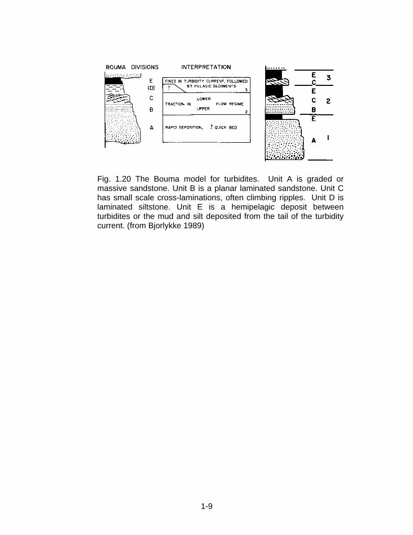
Fig. 1.20 The Bouma model for turbidites. Unit A is graded or massive sandstone. Unit B is a planar laminated sandstone. Unit C has small scale cross-laminations, often climbing ripples. Unit D is laminated siltstone. Unit E is a hemipelagic deposit between turbidites or the mud and silt deposited from the tail of the turbidity current. (from Bjorlykke 1989)
1-9
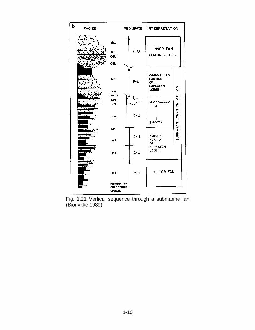
Fig. 1.21 Vertical sequence through a submarine fan (Bjorlykke 1989)
1-10
Carbonate Facies (Bjorlykke, 1989)
The carbonate sediments constitute a large group of varied origin. Common to them all is that they consist largely of carbonate minerals. They may be deposited as biogenic sediments, as chemical precipitates, or less commonly as clastic sediments eroded from other carbonate rocks. We often find clastic carbonate grains forming a minor component of sandstone and conglomerates. Because carbonates are less resistant to transport and weathering than quartz and feldspar, the clastic carbonate content of sediments will tend to decline with increasing transport and weathering.
We distinguish between carbonate fragments (clasts) from older carbonate beds which have become exposed to form an external source for a basin (e.vtrabasinurl clasts) and clasts formed locally within the basin through mechanical breakdown or biological fragmentation of sediment crusts or fossil aggregates. These are intrabasinal clasts (intraclasts) which are about the same age as the matrix.
The first condition for obtaining relatively pure carbonate deposits is that there must be very little supply of clastic material. This puts an important limitation on the occurrence of carbonate sediments.
Carbonate deposits occur in the following environments: 1. Carbonate Platforms and Reef Environments Along the Coast. They require
clear water and can form only outside the range of clastic sediment supplies from land. In dry areas, in particular, there will be very little runoff from land, which could add clastic sediments. The drainage pattern also plays a major role.
2. Tidal and Supratidal Environments Along the Coast. Form first and foremost in dry areas.
3. Reef and Carbonate Platforms Surrounded by Deep Ocean (e.g. the Bahamas) or atolls - carbonate reefs topping volcanic seamounts in the ocean basins. The ocean basin on the landward side will function as a trap for clastic sediments (Fig. 1.22). In such an environment carbonate sedimentation may continue for long geological periods. Carbonate production has to keep pace with the subsidence of the sea floor or the rise in sea level, so that the area does not sink below the photic zone. The Bahamas platform represents the build-up of carbonate from Jurassic-Cretaceous times right up to the present, and forms a very steep slope out to the ocean basins.
Warm water carbonates of this type contain a varied fauna of carbonate-secreting organisms, including hermatypic corals and green algae, and are often referred to as chlorozoan associations (Lees and Buller 1972).
1-11

Fig. 1.22 Distribution of carbonate sediments across the Atlantic Ocean
4. Carbonate Turbidites on Slopes Skirting Carbonate Platforms. They may be
formed from carbonate sand and mud, which is stirred up during storms over shallow water and transported, down the slopes. Mud flows, debris flows and submarine breccias may also form, as carbonate platforms often have very steep slopes.
5. Carbonate Sediment Formed from the Remains of Carbonate-Producing Pelagic Organisms. The most important off these are foraminifera and coccolithophores, a type of algae, which secrete small calcite shells. Since the planktonic carbonate organisms are small, pelagic carbonate deposits form a fine-grained ooze of clay and silt size, with occasional larger fossil fragments. Large areas of the South Atlantic and the Pacific are covered by sediment which contains more than 50% CaC03 from planktonic calcareous organisms. At depths greater than 4000-5000 m, the solubility of CaC03 becomes too great, and the carbonate percentage declines. Planktonic carbonates may also be deposited in shallow ocean areas, and the chalk deposits of Northwest Europe from Cretaceous times are a good example of this. The depth of water here was only a few hundred meters below the photic zone. The major carbonate-producing planktonic organisms, such as foraminifera and coccolithophores, have only existed since mid-Mesozoic times. Consequently we do not have chalk deposits or deep-water pelagic carbonates from older periods, when most carbonate production took place in shallow water.
6. Bioclastic Carbonate Deposits in Temperate and Cold Ocean Areas. The biological precipitation of carbonate does not depend on whether the water is warm or saturated with calcium carbonate. On the contrary, we often find highest productivity in cold areas because the water there is richer in
1-12
nutrients, particularly in areas of upwelling. Even if the water is undersaturated respect to carbonate, so that carbonate begins to dissolve as soon as the organisms die, carbonate will be deposited if the rate of production of carbonate is faster than the rate of solution. Carbonate will also be deposited in shallow areas, which do not receive clastic sediments. The Spitsbergen Bank northwest of Bear Island in the Barents Sea is a good example of this (Bjorlykke et al. 1978). This area, which is from 30-100 m deep, is surrounded by deeper channels, and therefore receives little clastic matter. The area lies on a cold front where cold currents from the north and east mix with the warmer water of the Atlantic Ocean. We find similar carbonate deposits on other banks off North America, for example Grand Bank, and along the coasts of western Scotland and Norway we find Holocene carbonate deposits which form a shell gravel.
Cold-water carbonates consist mainly of mollusks, benthic foraminifera, barnacles, bryozoa and calcareous red algae. and are called a foraminiferal association (Lees and Buller 1972).
7. Evaporite Basins. In ocean areas with normal salinity, practically all deposition of carbonate takes place by way of biological precipitation. In ocean areas with somewhat higher salinity, for example in the Persian Gulf, however, chemical precipitation of calcium carbonate may occur. Here too this precipitation may nevertheless be linked to biological factors. Periods when algae flourish in the surface water entail photosynthesis and consumption of CO2. This raises the pH, creating oversaturation and thus favorable conditions for chemical precipitation. Carbonates make up a small percentage of the salt precipitated when seawater evaporates to dryness. However, they are among the least soluble of the common salts in restricted ocean basins where the salinity is too low for the more soluble salts to precipitate (e.g. NaCl). Carbonates and sulfates often form thick evaporite sequences.
8. Lakes and Inland Seas. Lacustrine sediments may also contain considerable amounts of carbonate, and at lower latitudes in particular we find pure carbonate beds. In cold lakes the solubility of carbonate will be relatively high, and the carbonate content will tend mostly to be biogenic (e.g. mollusks). In lakes in temperate areas we also get calcareous sediments (marls) deposited. Algae often play an important role in carbonate production in lakes, and certain higher plants, which grow in lakes, can also precipitate carbonate.
The Dead Sea is a good example of an inland sea where carbonate is precipitated chemically due to strong evaporation. In Africa and other tropical areas, lakes will be subject to seasonal evaporation to dryness, and we may find alternation between biogenic carbonate layers and chemically precipitated carbonate. Here again, the production of diatoms and algae in the surface water layer consumes CO2. (increasing the pH) and plays a major role in the precipitation of carbonate. Mollusks (bivalves and
1-13
gastropods) and algae are important components of freshwater carbonates as well as chemically precipitated carbonate.
9. Calcareous Tufa Deposits and Travertine. Tufa is the name of a porous limestone that is precipitated where groundwater flows out at the surface or comes into contact with the atmosphere, as in limestone caves or springs. When it is inside rock, groundwater will have a higher partial pressure of CO2 that can remain in solution due to the lower temperature and higher pressure than at the surface. When water flows out of the rock, it will give up CO2 and in summer at least, will warm up so that carbonate is precipitated mainly as calcite. Exposure to light will also cause biogenic precipitation (photosynthesis). Evaporation may also enrich the water and lead to precipitation. Calcareous tufa is common in areas with limestone, and deposits often create good molds of plants and occasionally even of animals. Travertine is a more massive, banded (laminated) carbonate which has been used as a decorative stone, particularly in Mediterranean countries.
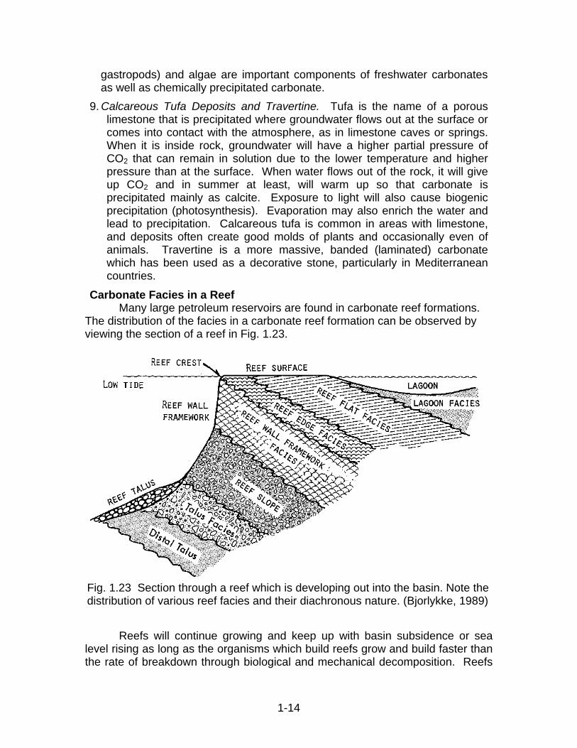
Carbonate Facies in a Reef Many large petroleum reservoirs are found in carbonate reef formations. The distribution of the facies in a carbonate reef formation can be observed by viewing the section of a reef in Fig. 1.23.
Reefs will continue growing and keep up with basin subsidence or sea level rising as long as the organisms which build reefs grow and build faster than the rate of breakdown through biological and mechanical decomposition. Reefs
Fig. 1.23 Section through a reef which is developing out into the basin. Note the distribution of various reef facies and their diachronous nature. (Bjorlykke, 1989)
1-14

will grow fastest on the outside, where wave power and supply of nutrients is greatest. In case of barrier reefs, a lagoon forms on the inside and fills with fine-grained carbonate sediment eroded from the reef, and also from the green algae which live in a lagoon environment. Free-standing reefs will form a ring with a lagoon in the middle. The reef will be sensitive to changes in sea level since reef organisms do not tolerate exposure or “drowning” below the photic zone. Modern reefs have a very high porosity, made up of everything from small holes to large caverns. Boring and blasting into these reefs revealed that the hollows rapidly filled up with cement, fragments of fossils or lime mud, and little porosity remains. Even in the framework facies we find that much of the porosity is secondary, due to the solution of fossils or cement. Fossils which consist of arogonite or high magnesium calcite will dissolve particularly easily, and low Mg calcite will form. The diagenetic process may not cause a strong increase in the overall porosity, but a redistribution of primary porosity. Reefs are often surrounded by organically rich shale which may form source rocks. Reefs are good hydrocarbon traps, because they project up from the sea-bed, thereby constituting projecting structures, which may become sealed when the reef drowns and is covered by shale.
1-15

Alterations The structure of sediments soon becomes altered from the configuration it had at deposition. Macroscopic alterations occur due to deformation of the earth’s crust or tectonic activity and erosion. Some other alteration mechanisms will be discussed below.
Compaction Well-sorted sand has a porosity of 35-45%, whereas recently deposited clay contains 50-80% water. As additional sediment settles on the deposit, the overburden compresses the clay and it will compact as it loses water. Compacted clay is called shale. This results in the rapid (on a geological time scale) subsidence that is common in coastal areas of recent deposits. Because of different degree of compaction between sand and clay, the subsidence will not be uniform between areas under laid by clay and by sand. This will result in deformation of the overlying formations.
Buoyancy Salt domes are formed because salt is less dense than the overlying rock, and the salt “flows” upward due to buoyancy. Figure 1.22 illustrates a cross section of a salt dome and the oil and gas traps that are often associated with a salt dome structure. Salt domes often alter the earth’s surface features, e.g., High Island, Texas. Early oil prospectors often looked for a hill in an otherwise flat coastal plain. Now subsurface salt domes are easily detected by seismic prospecting
Fig. 1.22 Illustration of a salt dome (Bjorlykke, 1989)
1-16
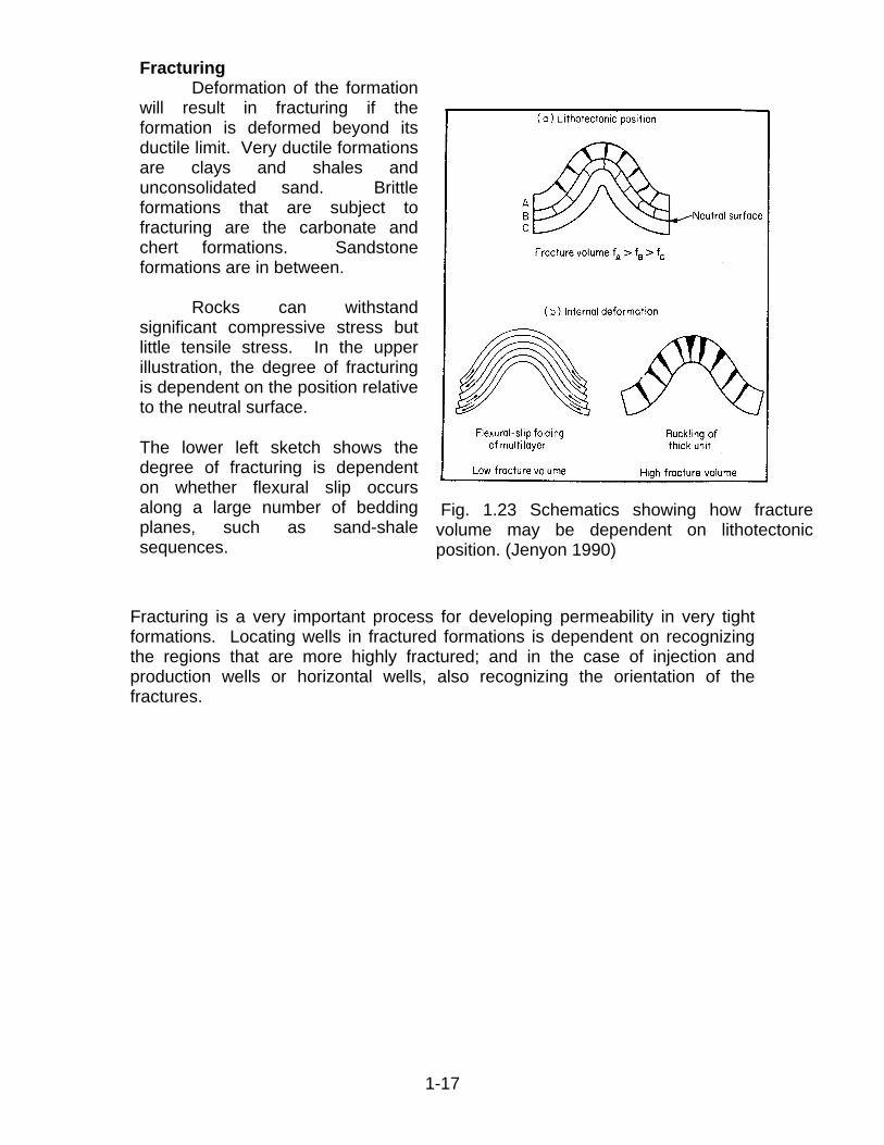
Fig. 1.23 Schematics showing how fracture
lume may be dependent on lithotectonic position. (Jenyon 1990) vo
The lower left sketch shows the degree of fracturing is dependent on whether flexural slip occurs along a large number of bedding planes, such as sand-shale sequences.
Fracturing Deformation of the formation will result in fracturing if the formation is deformed beyond its ductile limit. Very ductile formations are clays and shales and unconsolidated sand. Brittle formations that are subject to fracturing are the carbonate and chert formations. Sandstone formations are in between. Rocks can withstand significant compressive stress but little tensile stress. In the upper illustration, the degree of fracturing is dependent on the position relative to the neutral surface.
Fracturing is a very important process for developing permeability in very tight formations. Locating wells in fractured formations is dependent on recognizing the regions that are more highly fractured; and in the case of injection and production wells or horizontal wells, also recognizing the orientation of the fractures.
1-17

Faulting After a formation deforms beyond some limiting amount it will fracture and the two sides will be displaced relative to each other. A fracture with displacement is called a fault. Figure 1.24 illustrates the different types of faults. If a permeable formation is displaced by a fault such that it is against an impermeable formation, the fault may act as a no flow boundary of the formation or a sealing fault.
Fig. 1.24 Principle types of faults (Jenyon 1990)
The types of faults illustrated above are (a) normal fault, (b) reverse fault, (c) strike-slip fault, (d) oblique-slip fault, (e) thrust fault, and (f) listric fault.
1-18
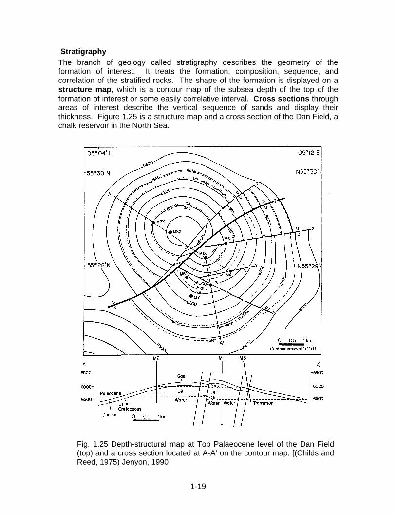
Stratigraphy The branch of geology called stratigraphy describes the geometry of the formation of interest. It treats the formation, composition, sequence, and correlation of the stratified rocks. The shape of the formation is displayed on a structure map, which is a contour map of the subsea depth of the top of the formation of interest or some easily correlative interval. Cross sections through areas of interest describe the vertical sequence of sands and display their thickness. Figure 1.25 is a structure map and a cross section of the Dan Field, a chalk reservoir in the North Sea.
Fig. 1.25 Depth-structural map at Top Palaeocene level of the Dan Field (top) and a cross section located at A-A’ on the contour map. [(Childs and Reed, 1975) Jenyon, 1990]
1-19
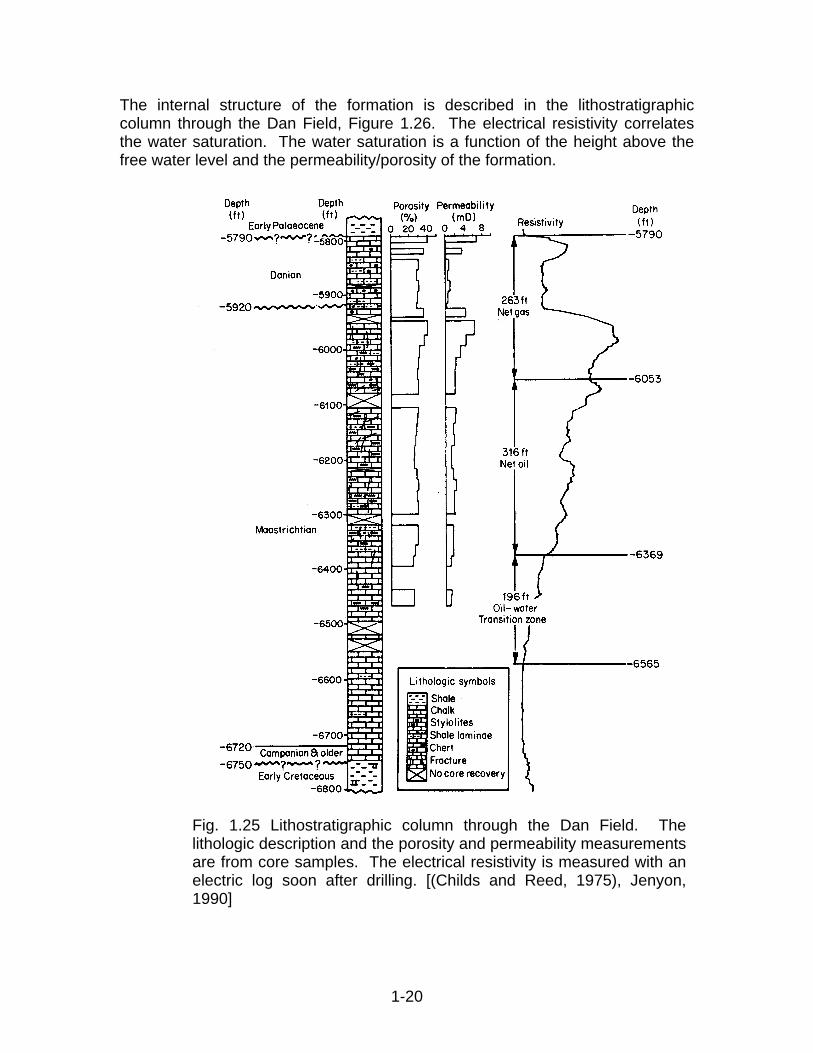
The internal structure of the formation is described in the lithostratigraphic column through the Dan Field, Figure 1.26. The electrical resistivity correlates the water saturation. The water saturation is a function of the height above the free water level and the permeability/porosity of the formation.
Fig. 1.25 Lithostratigraphic column through the Dan Field. The lithologic description and the porosity and permeability measurements are from core samples. The electrical resistivity is measured with an electric log soon after drilling. [(Childs and Reed, 1975), Jenyon, 1990]
1-20

Seismic Stratrigraphy
Information on the stratigraphy of a reservoir will be very sparse if we have to depend on well logs, especially in a field before wells are drilled. The first estimate of stratrigraphy is from seismic records measured from a series of geophones in response to an acoustic source. Since the source and response are usually measured along the ground surface or sea surface, the measurements are a time trace of reflections or echos from reflectors in the subsurface.
Interpretation of the seismic record requires an understanding of its relation to rock properties. We know from hydrodynamics that the velocity of a pressure wave (i.e., speed of sound) in a homogeneous fluid is equal to the square root of the recriprocal of the change in density with change in pressure at constant entropy. We know that the speed of sound in dry air at one atmosphere is about 0.35 km/s. Water is less compressible than air and thus has an acoustic velocity of about 1.5 km/s. Solids can transmit both longitudinal waves and shear waves, however, we will not make the distinction here. (Fused silica has longitidunal and shear velocities of 6.0 km/s and 3.8 km/s, respectively) Rocks are a composite medium of minerals and fluids and a model is needed to describe it velocity. The Wyllie’s equation expresses the rock’s acoustic velocity as a function of porosity.
1 1
r mV V Vf
φ φ−= +
where Vr = acoustic velocity of rock saturated with fluid Vm = acoustic velocity of matrix or mineral Vf = acoustic velocity of fluid φ = porosity
Acoustic velocity (especially the shear velocity) is also dependent of the contact between the mineral particles. Cementation of sand grains will increase the velocity. Thus consolidated rock will have a higher velocity, with everything else the same. Acoustic signals return to the surface as a result of echos or reflections from surfaces of contrasting acoustic properties. The coefficient of reflectivity depends on the acoustic impedance, which is the product of velocity and density.
2 2 1 1
2 2 1 1
V VRV V
ρ ρρ ρ
−=
+
The vertical seismic profile can be calibrated will well logs. The example below illustrates how the lithology, acoustic velocity and density logs can be used to generate synthetic seismograms to interpret a vertical seismic profile.
1-21
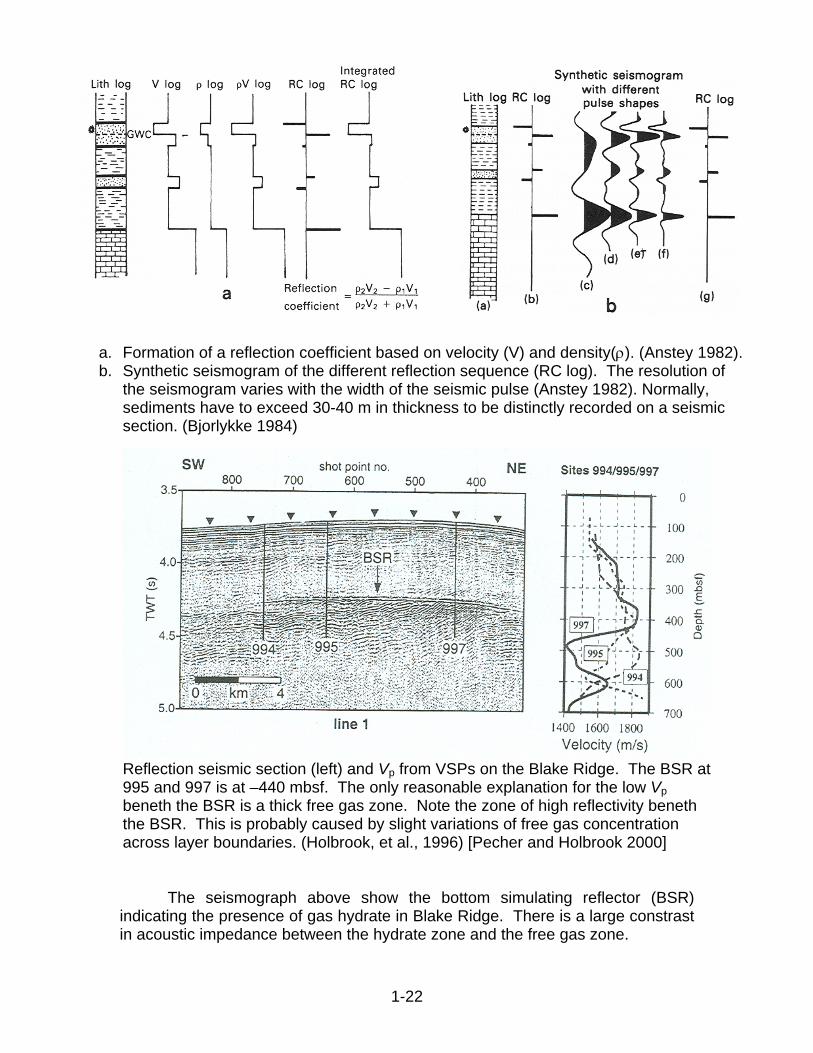
a. Formation of a reflection coefficient based on velocity (V) and density(ρ). (Anstey 1982). b. Synthetic seismogram of the different reflection sequence (RC log). The resolution of
the seismogram varies with the width of the seismic pulse (Anstey 1982). Normally, sediments have to exceed 30-40 m in thickness to be distinctly recorded on a seismic section. (Bjorlykke 1984)
Reflection seismic section (left) and Vp from VSPs on the Blake Ridge. The BSR at995 and 997 is at –440 mbsf. The only reasonable explanation for the low Vp beneth the BSR is a thick free gas zone. Note the zone of high reflectivity beneth the BSR. This is probably caused by slight variations of free gas concentration across layer boundaries. (Holbrook, et al., 1996) [Pecher and Holbrook 2000]
The seismograph above show the bottom simulating reflector (BSR) indicating the presence of gas hydrate in Blake Ridge. There is a large constrast in acoustic impedance between the hydrate zone and the free gas zone.
1-22
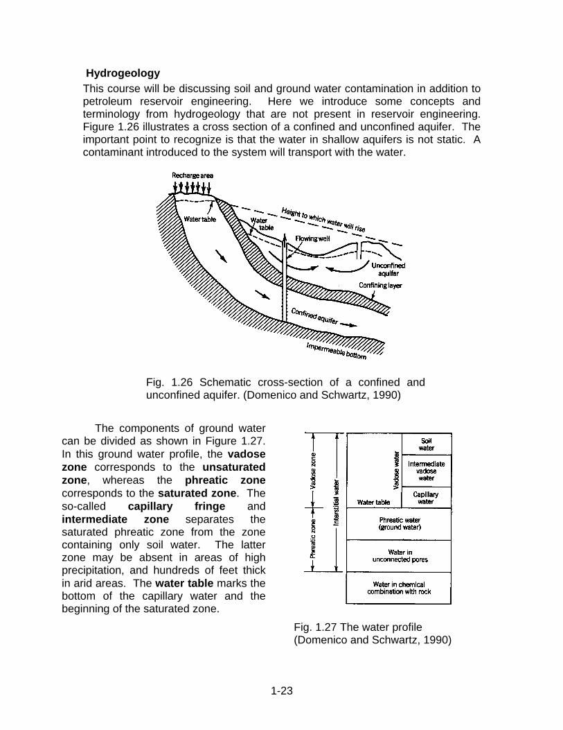
Hydrogeology This course will be discussing soil and ground water contamination in addition to petroleum reservoir engineering. Here we introduce some concepts and terminology from hydrogeology that are not present in reservoir engineering. Figure 1.26 illustrates a cross section of a confined and unconfined aquifer. The important point to recognize is that the water in shallow aquifers is not static. A contaminant introduced to the system will transport with the water.
Fig. 1.26 Schematic cross-section of a confined and unconfined aquifer. (Domenico and Schwartz, 1990)
The components of ground water can be divided as shown in Figure 1.27. In this ground water profile, the vadose zone corresponds to the unsaturated zone, whereas the phreatic zone corresponds to the saturated zone. The so-called capillary fringe and intermediate zone separates the saturated phreatic zone from the zone containing only soil water. The latter zone may be absent in areas of high precipitation, and hundreds of feet thick in arid areas. The water table marks the bottom of the capillary water and the beginning of the saturated zone.
Fig. 1.27 The water profile (Domenico and Schwartz, 1990)
1-23

Migration and Accumulation of Hydrocarbon The petroleum in oil reservoirs was generated from organic material called kerogen in rock that is called the source rock. As the kerogen matures under the action of temperature and time, some liquid hydrocarbon phase may be generated. If the liquid hydrocarbon exists at a saturation that is high enough or if the solid phases have sufficient oil-wetting surfaces it can exist as a continuous phase. Since hydrocarbon is less dense than water, it will then percolate upward through the water filled rock. This process is called oil migration. If there is a barrier or trap to stop this upward migration of oil, then oil will accumulate in this trap. Some common types of traps are shown in Figure 1.27.
Fig. 1.27 Common traps for accumulation of hydrocarbon (Bjorlykke, 1989)
1-24

Bibliography Bjorlykke, K., Sedimentology and Petroleum Geology, Springer-Verlag, New York, 1989. Domenico, P. A. and Schwartz, F. W., Physical and Chemical Hydrogeology, John Wiley & Sons, New York, 1990. Jenyon, M. K., Oil and Gas Traps - Aspects of their Seismostratigraphy, Morphology, and Development, John Wiley & Sons, 1990.
1-25
Related Documents