Document Number EDCS-572658 Revision 5.0 Cisco BTS 10200 Softswitch Software Upgrade for Release 4.4.0 to 4.5.1 MR1 March 21, 2007 Corporate Headquarters Cisco Systems, Inc. 170 West Tasman Drive San Jose, CA 95134-1706 USA http://www.cisco.com Tel: 408 526-4000 800 553-NETS (6387) Fax:408 526-4100

Welcome message from author
This document is posted to help you gain knowledge. Please leave a comment to let me know what you think about it! Share it to your friends and learn new things together.
Transcript

Document Number EDCS-572658 Revision 5.0
Cisco BTS 10200 Softswitch Software Upgrade for Release4.4.0 to 4.5.1 MR1
March 21, 2007
Corporate HeadquartersCisco Systems, Inc.170 West Tasman DriveSan Jose, CA 95134-1706USAhttp://www.cisco.comTel: 408 526-4000
800 553-NETS (6387)Fax: 408 526-4100

THE SPECIFICATIONS AND INFORMATION REGARDING THE PRODUCTS IN THIS MANUAL ARE SUBJECT TO CHANGE WITHOUT NOTICE. ALL STATEMENTS, INFORMATION, AND RECOMMENDATIONS IN THIS MANUAL ARE BELIEVED TO BE ACCURATE BUT ARE PRESENTED WITHOUT WARRANTY OF ANY KIND, EXPRESS OR IMPLIED. USERS MUST TAKE FULL RESPONSIBILITY FOR THEIR APPLICATION OF ANY PRODUCTS.
THE SOFTWARE LICENSE AND LIMITED WARRANTY FOR THE ACCOMPANYING PRODUCT ARE SET FORTH IN THE INFORMATION PACKET THAT SHIPPED WITH THE PRODUCT AND ARE INCORPORATED HEREIN BY THIS REFERENCE. IF YOU ARE UNABLE TO LOCATE THE SOFTWARE LICENSE OR LIMITED WARRANTY, CONTACT YOUR CISCO REPRESENTATIVE FOR A COPY.
The Cisco implementation of TCP header compression is an adaptation of a program developed by the University of California, Berkeley (UCB) as part of UCB’s public domain version of the UNIX operating system. All rights reserved. Copyright © 1981, Regents of the University of California.
NOTWITHSTANDING ANY OTHER WARRANTY HEREIN, ALL DOCUMENT FILES AND SOFTWARE OF THESE SUPPLIERS ARE PROVIDED “AS IS” WITH ALL FAULTS. CISCO AND THE ABOVE-NAMED SUPPLIERS DISCLAIM ALL WARRANTIES, EXPRESSED OR IMPLIED, INCLUDING, WITHOUT LIMITATION, THOSE OF MERCHANTABILITY, FITNESS FOR A PARTICULAR PURPOSE AND NONINFRINGEMENT OR ARISING FROM A COURSE OF DEALING, USAGE, OR TRADE PRACTICE.
IN NO EVENT SHALL CISCO OR ITS SUPPLIERS BE LIABLE FOR ANY INDIRECT, SPECIAL, CONSEQUENTIAL, OR INCIDENTAL DAMAGES, INCLUDING, WITHOUT LIMITATION, LOST PROFITS OR LOSS OR DAMAGE TO DATA ARISING OUT OF THE USE OR INABILITY TO USE THIS MANUAL, EVEN IF CISCO OR ITS SUPPLIERS HAVE BEEN ADVISED OF THE POSSIBILITY OF SUCH DAMAGES.
CCIP, CCSP, the Cisco Arrow logo, the Cisco Powered Network mark, the Cisco Systems Verified logo, Cisco Unity, Follow Me Browsing, FormShare, iQ Breakthrough, iQ FastTrack, the iQ Logo, iQ Net Readiness Scorecard, Networking Academy, ScriptShare, SMARTnet, TransPath, and Voice LAN are trademarks of Cisco Systems, Inc.; Changing the Way We Work, Live, Play, and Learn, The Fastest Way to Increase Your Internet Quotient, and iQuick Study are service marks of Cisco Systems, Inc.; and Aironet, ASIST, BPX, Catalyst, CCDA, CCDP, CCIE, CCNA, CCNP, Cisco, the Cisco Certified Internetwork Expert logo, Cisco IOS, the Cisco IOS logo, Cisco Press, Cisco Systems, Cisco Systems Capital, the Cisco Systems logo, Empowering the Internet Generation, Enterprise/Solver, EtherChannel, EtherSwitch, Fast Step, GigaStack, Internet Quotient, IOS, IP/TV, iQ Expertise, LightStream, MGX, MICA, the Networkers logo, Network Registrar, Packet, PIX, Post-Routing, Pre-Routing, RateMUX, Registrar, SlideCast, StrataView Plus, Stratm, SwitchProbe, TeleRouter, and VCO are registered trademarks of Cisco Systems, Inc. and/or its affiliates in the U.S. and certain other countries.
All other trademarks mentioned in this document or Web site are the property of their respective owners. The use of the word partner does not imply a partnership relationship between Cisco and any other company. (0301R)
Cisco BTS 10200 Softswitch Software Upgrade
Copyright © 2005, Cisco Systems, Inc.
All rights reserved.
Cisco BTS 10200 Softswitch Software UpgradePage 2

Revision History Date Version Description01/29/2007 1.0 Initial Version03/09/2007 2.0 Added IP00 Patch Procedure03/21/2007 5.0 Added IP01 Patch Procedure
Cisco BTS 10200 Softswitch Software UpgradePage 3

Table of ContentsTable of Contents.................................................................................................................4Table of Contents.................................................................................................................4Preface...............................................................................................................................10Obtaining Documentation..................................................................................................10
World Wide Web.......................................................................................................10Documentation CD-ROM..........................................................................................10Ordering Documentation...........................................................................................10Documentation Feedback..........................................................................................11
Obtaining Technical Assistance........................................................................................11Cisco.com..................................................................................................................11Technical Assistance Center......................................................................................12Cisco TAC Web Site.................................................................................................12Cisco TAC Escalation Center....................................................................................13
Chapter 1............................................................................................................................14Upgrade Requirements......................................................................................................14Introduction........................................................................................................................14Assumptions......................................................................................................................15Requirements.....................................................................................................................15Important notes about this procedure................................................................................16Chapter 2............................................................................................................................18Preparation.........................................................................................................................18Referenced documents.......................................................................................................18Prerequisites.......................................................................................................................19. Chapter 3..........................................................................................................................20Chapter 3............................................................................................................................21Complete one week before the scheduled upgrade............................................................21Task 1: Add new domain names to DNS...........................................................................21Task 2: Pre-construct opticall.cfg for the system to be upgraded to 4.5.1 MR1 release.. .22Task 3: Verify value of CA CONTROL PORT for IVR devices connected to BTS.
...........................................................................................................................................23Note : The value of the CA_CONTROL_PORT for IVR devices connected to BTS should not be 0...................................................................................................................23From Active EMS..............................................................................................................23Task 4: Verify Default routes............................................................................................27
...........................................................................................................................................27Note : Verify that there are a total of 4 default routes on CA (including primary and secondary) and ensure that they are on the correct (signaling) VLANS...........................27Chapter 4............................................................................................................................28Complete the night before the scheduled upgrade.............................................................28Task 1: Check mlhg_terminal table...................................................................................28From Active EMS..............................................................................................................28
Cisco BTS 10200 Softswitch Software UpgradePage 4

Task 2: Check SLE table...................................................................................................28From Active EMS..............................................................................................................29Task 3: Check Feature table..............................................................................................29From Active EMS..............................................................................................................29Task 4: Check Feature table and Service-trigger table......................................................29From Active EMS..............................................................................................................29Task 5: Save customized cron jobs....................................................................................31From Each BTS machine...................................................................................................31Task 6 : Perform full database audit..................................................................................31Note : Depending on the size of the database the audit could take multiple hours to complete. This task should be completed the night before the upgrade............................31Chapter 5............................................................................................................................32Prepare System for Upgrade..............................................................................................32Task 1: Verify System Status............................................................................................32Task 2: Perform database row count audit (sanity check).................................................32Task 3: Alarms...................................................................................................................33Verify that there are no outstanding major or critical alarms. Use Appendix D for this procedure...........................................................................................................................33Task 4: Oracle Database and Replication..........................................................................33Use Appendix E to verify that Oracle database and replication functions are working properly..............................................................................................................................33Task 5: Backup user account.............................................................................................33From EMS Side A.............................................................................................................33Task 6: Verify and record Virtual IP (VIP) information...................................................34From EMS Side A.............................................................................................................34Task 7: Verify and record VSM Macro information.........................................................34From EMS Side A.............................................................................................................35Chapter 6............................................................................................................................36Upgrade Side B Systems...................................................................................................36Task 1: Block provisioning path........................................................................................36Task 2: Disable Oracle DB replication..............................................................................36From Active EMS..............................................................................................................36From EMS side A..............................................................................................................36Task 3: Force side A systems to active..............................................................................37From Active EMS Side B..................................................................................................37Task 4: Inhibit EMS mate communication........................................................................38From EMS side A..............................................................................................................38Task 5: Stop applications and shutdown EMS side B.......................................................38From EMS side B..............................................................................................................38Task 6: Stop applications and shutdown CA/FS side B....................................................39From CA/FS side B...........................................................................................................39Task 7: Upgrade EMS side B to the new release...............................................................39From EMS side B..............................................................................................................39Task 8: Upgrade CA/FS Side B to the new release...........................................................45From CA/FS side B...........................................................................................................45Task 9: Migrate oracle data...............................................................................................50
Cisco BTS 10200 Softswitch Software UpgradePage 5

From EMS side B..............................................................................................................50Chapter 7............................................................................................................................52Prepare Side A Systems for Upgrade................................................................................52Task 1: Force side A systems to standby...........................................................................52From EMS side A..............................................................................................................52Task 2: Check and Correct Feature Server and Call Agent TSAP address.......................53From EMS side B..............................................................................................................53Task 3: Sync Data from EMS side B to CA/FS side B.....................................................55From EMS side B..............................................................................................................55Task 4: Block Provisioning Path......................................................................................55From EMS side B..............................................................................................................55Task 5: Validate release 4.5.1 MR1 software operation....................................................56From EMS side B..............................................................................................................56Task 6: Ftp billing records off the system.........................................................................57From EMS side A..............................................................................................................57Chapter 8............................................................................................................................58Upgrade Side A Systems...................................................................................................58Task 1: Stop applications and shutdown EMS side A.......................................................58From EMS side A..............................................................................................................58Task 2: Stop applications and shutdown CA/FS side A....................................................58From CA/FS side A...........................................................................................................58Task 3: Upgrade EMS side A to the new release..............................................................59From EMS side A..............................................................................................................59Task 4: Upgrade CA/FS Side A to the new release...........................................................63From CA/FS side A...........................................................................................................63Task 5: Restore Hub communication................................................................................67From EMS side B..............................................................................................................67Task 6: Copying oracle data..............................................................................................68From EMS side A..............................................................................................................68Task 7: Verify Hub communication..................................................................................69From EMS side B..............................................................................................................69Chapter 9............................................................................................................................70Finalizing Upgrade............................................................................................................70Task 1: Switchover activity from side B to side A............................................................70From EMS side B..............................................................................................................70Task 2: Enable Oracle DB replication on EMS side B......................................................70From EMS side B..............................................................................................................70Task 3 : Enable Provisioning Path
...........................................................................................................................................71From EMS side B..............................................................................................................71Task 4: Check and correct sctp-assoc table.......................................................................71From EMS side A..............................................................................................................72Task 5: Synchronize handset provisioning data................................................................72From EMS side A..............................................................................................................72Task 6: SFTP hosts and opticall.cfg file............................................................................73
Cisco BTS 10200 Softswitch Software UpgradePage 6

Task 7: Restore customized cron jobs...............................................................................73From EMS side A..............................................................................................................73From EMS side B..............................................................................................................74From CA side B.................................................................................................................74Task 8: Reconfigure VSM Macro information..................................................................75Task 9: To install CORBA on EMS side A and B, please follow Appendix I..................76Task 10: Verify system status............................................................................................76Appendix A........................................................................................................................77Check System Status..........................................................................................................77From Active EMS side A..................................................................................................77Appendix B........................................................................................................................80Check Call Processing.......................................................................................................80From EMS side A..............................................................................................................80Appendix C........................................................................................................................82Check Provisioning and Database.....................................................................................82From EMS side A..............................................................................................................82Check transaction queue....................................................................................................82Perform database audit......................................................................................................83Appendix D........................................................................................................................84Check Alarm Status...........................................................................................................84From EMS side A..............................................................................................................84Appendix E........................................................................................................................86Check Oracle Database Replication and Error Correction................................................86Check Oracle DB replication status...................................................................................86From EMS side A..............................................................................................................86Correct replication error....................................................................................................87From EMS Side B..............................................................................................................87From EMS Side A.............................................................................................................88Appendix F........................................................................................................................89Backout Procedure for Side B Systems.............................................................................89Introduction........................................................................................................................89Task 1: Force side A CA/FS to active...............................................................................90From EMS side B..............................................................................................................91Task 2: Force side A EMS to active
...........................................................................................................................................91From EMS side B..............................................................................................................91Task 3: Sync TSAP-ADDR
...........................................................................................................................................91From EMS side A..............................................................................................................91Task 4: SFTP billing records to a mediation device..........................................................91From EMS side B..............................................................................................................92Task 5: Sync DB usage......................................................................................................92From EMS side A..............................................................................................................92Task 6: Stop applications and shutdown side B systems...................................................92
Cisco BTS 10200 Softswitch Software UpgradePage 7

From EMS side B..............................................................................................................92From CA/FS side B...........................................................................................................93Task 7: Restore side B systems to the old release.............................................................93From CA/FS side B...........................................................................................................93From EMS side B..............................................................................................................94Task 8: Restore EMS mate communication......................................................................95From EMS side A..............................................................................................................95Task 9: Switchover activity to EMS side B.......................................................................95From Active EMS side A..................................................................................................95Task 10: Enable Oracle DB replication on EMS side A...................................................95From EMS side A..............................................................................................................96Task 11: Synchronize handset provisioning data..............................................................96From EMS side B..............................................................................................................96Task 12: Switchover activity from EMS side B to EMS side A.......................................97From EMS side B..............................................................................................................97Task 13: Restore system to normal mode..........................................................................97From EMS side A..............................................................................................................97Task 14: Verify system status............................................................................................98Appendix G........................................................................................................................99Software Upgrade Disaster Recovery Procedure..............................................................99Assumptions......................................................................................................................99Requirements...................................................................................................................100Important notes about this procedure..............................................................................100System Disaster Recovery Procedure..............................................................................101Task 1: Shutdown each machine.....................................................................................101Task 2: Restore CA/FS side B to the old release.............................................................103Task 3: Bring up applications on CA/FS side B..............................................................104Task 4: Restore EMS side B to the old release................................................................104Task 5: Verify system health...........................................................................................104Task 6: Restore CA/FS side A to the old release.............................................................106Task 7: Restore EMS side A to the old release...............................................................107Task 8:Enable Bulk Provisioning from EMS side A & B...............................................109Task 9: Verify system status............................................................................................109Appendix H......................................................................................................................112Preparing Disks for Upgrade...........................................................................................112Task 1: Locate CD-ROM Discs.......................................................................................112Task 2: Locate and label the Disks..................................................................................112Label disks for EMS Side A............................................................................................112Label Disks for EMS Side B...........................................................................................113Label Disks for CA/FS Side A........................................................................................113Label Disks for CA/FS Side B.........................................................................................113Task 3: Disk slot lay out..................................................................................................113Task 4: Construct opticall.cfg..........................................................................................114Task 5: Disk preparation..................................................................................................114For both EMS side A and B.............................................................................................114For both CA/FS side A and B..........................................................................................118
Cisco BTS 10200 Softswitch Software UpgradePage 8

Appendix I.......................................................................................................................121CORBA Installation.........................................................................................................121Task 1: Open Unix Shell on EMS...................................................................................121Task 2: Install OpenORB CORBA Application..............................................................121
Remove Installed OpenORB Application...............................................................121Install OpenORB Packages......................................................................................122
Appendix J.......................................................................................................................124Block Provisioning Path..................................................................................................124From EMS side A and B..................................................................................................124Appendix K......................................................................................................................126Files handled by DoTheChange script.............................................................................126Appendix L......................................................................................................................128Disable and Enable Radius Server...................................................................................128Task 1: Disable Radius Server.........................................................................................128From Each Machine.........................................................................................................128Task 2: Enable Radius Server..........................................................................................128From Each Machine.........................................................................................................128Appendix M.....................................................................................................................129Install IP01 Patch on EMS...............................................................................................129Appendix N......................................................................................................................130Install IP01 Patch on CA.................................................................................................130Backout Procedure for IP01 Patch...................................................................................131
Cisco BTS 10200 Softswitch Software UpgradePage 9

Preface
Obtaining Documentation
These sections explain how to obtain documentation from Cisco Systems.
World Wide Web
You can access the most current Cisco documentation on the World Wide Web at this URL: http://www.cisco.com/
Translated documentation is available at this URL: http://www.cisco.com/public/countries_languages.shtml
Documentation CD-ROM
Cisco documentation and additional literature are available in a Cisco Documentation CD-ROM package, which is shipped with your product. The Documentation CD-ROM is updated monthly and may be more current than printed documentation. The CD-ROM package is available as a single unit or through an annual subscription.
Ordering Documentation
You can order Cisco documentation in these ways:
Registered Cisco.com users (Cisco direct customers) can order Cisco product documentation from the Networking Products MarketPlace: http://www.cisco.com/cgi-bin/order/order_root.pl
Registered Cisco.com users can order the Documentation CD-ROM through the online Subscription Store: http://www.cisco.com/go/subscription
Nonregistered Cisco.com users can order documentation through a local account representative by calling Cisco Systems Corporate Headquarters (California, U.S.A.) at 408 526-7208 or, elsewhere in North America, by calling 800 553-NETS (6387).
Cisco BTS 10200 Softswitch Software UpgradePage 10

Documentation Feedback
You can submit comments electronically on Cisco.com. In the Cisco Documentation home page, click the Fax or Email option in the “Leave Feedback” section at the bottom of the page.
You can e-mail your comments to mailto:[email protected].
You can submit your comments by mail by using the response card behind the front cover of your document or by writing to the following address:
Cisco Systems, INC.
Attn: Document Resource Connection
170 West Tasman Drive
San Jose, CA 95134-9883
Obtaining Technical Assistance
Cisco provides Cisco.com as a starting point for all technical assistance. Customers and partners can obtain online documentation, troubleshooting tips, and sample configurations from online tools by using the Cisco Technical Assistance Center (TAC) Web Site. Cisco.com registered users have complete access to the technical support resources on the Cisco TAC Web Site: http://www.cisco.com/tac
Cisco.com
Cisco.com is the foundation of a suite of interactive, networked services that provides immediate, open access to Cisco information, networking solutions, services, programs, and resources at any time, from anywhere in the world.
Cisco.com is a highly integrated Internet application and a powerful, easy-to-use tool that provides a broad range of features and services to help you with these tasks:
Streamline business processes and improve productivity
Resolve technical issues with online support
Order Cisco learning materials and merchandise
Register for online skill assessment, training, and certification programs
Cisco BTS 10200 Softswitch Software UpgradePage 11

If you want to obtain customized information and service, you can self-register on Cisco.com. To access Cisco.com, go to this URL: http://www.cisco.com/
Technical Assistance Center
The Cisco Technical Assistance Center (TAC) is available to all customers who need technical assistance with a Cisco product, technology, or solution. Two levels of support are available: the Cisco TAC Web Site and the Cisco TAC Escalation Center.
Cisco TAC inquiries are categorized according to the urgency of the issue:
Priority level 4 (P4)—You need information or assistance concerning Cisco product capabilities, product installation, or basic product configuration.
Priority level 3 (P3)—Your network performance is degraded. Network functionality is noticeably impaired, but most business operations continue.
Priority level 2 (P2)—Your production network is severely degraded, affecting significant aspects of business operations. No workaround is available.
Priority level 1 (P1)—Your production network is down, and a critical impact to business operations will occur if service is not restored quickly. No workaround is available.
The Cisco TAC resource that you choose is based on the priority of the problem and the conditions of service contracts, when applicable.
Cisco TAC Web Site
You can use the Cisco TAC Web Site to resolve P3 and P4 issues yourself, saving both cost and time. The site provides around-the-clock access to online tools, knowledge bases, and software. To access the Cisco TAC Web Site, go to this URL: http://www.cisco.com/tac
All customers, partners, and resellers who have a valid Cisco service contract have complete access to the technical support resources on the Cisco TAC Web Site. The Cisco TAC Web Site requires a Cisco.com Log in ID and password. If you have a valid service contract but do not have a Log in ID or password, go to this URL to register: http://www.cisco.com/register/
If you are a Cisco.com registered user, and you cannot resolve your technical issues by using the Cisco TAC Web Site, you can open a case online by using the TAC Case Open tool at this URL: http://www.cisco.com/tac/caseopen
Cisco BTS 10200 Softswitch Software UpgradePage 12

If you have Internet access, we recommend that you open P3 and P4 cases through the Cisco TAC Web Site: http://www.cisco.com/tac
Cisco TAC Escalation Center
The Cisco TAC Escalation Center addresses priority level 1 or priority level 2 issues. These classifications are assigned when severe network degradation significantly impacts business operations. When you contact the TAC Escalation Center with a P1 or P2 problem, a Cisco TAC engineer automatically opens a case.
To obtain a directory of toll-free Cisco TAC telephone numbers for your country, go to this URL: http://www.cisco.com/warp/public/687/Directory/DirTAC.shtml
Before calling, please check with your network operations center to determine the level of Cisco support services to which your company is entitled: for example, SMARTnet, SMARTnet Onsite, or Network Supported Accounts (NSA). When you call the center, please have available your service agreement number and your product serial number.
Cisco BTS 10200 Softswitch Software UpgradePage 13

Chapter 1Upgrade Requirements
Introduction
Application software loads are designated as Release 900-aa.bb.cc.Vxx, where aa=major release number, for example, 01 bb=minor release number, for example, 03 cc=maintenance release, for example, 00 Vxx=Version number, for example V04
This procedure can be used on an in-service system, but the steps must be followed as shown in this document in order to avoid traffic interruptions.
Caution Performing the steps in this procedure will bring down and restart individual platforms in a specific sequence. Do not perform the steps out of sequence, as it could affect traffic. If you have questions, contact Cisco Support.
This procedure should be performed during a maintenance window.
Note In this document, the following designations are used:
EMS -- Element Management System CA/FS -- Call Agent / Feature Server Primary -- Also referred to as "Side A" Secondary -- Also referred to as "Side B"
Cisco BTS 10200 Softswitch Software UpgradePage 14

Assumptions
The following assumptions are made. The installer has a basic understanding of UNIX and Oracle commands. The installer has the appropriate user name(s) and password(s) to log on to each
EMS/CA/FS platform as root user, and as Command Line Interface (CLI) user on the EMS.
Note Contact Cisco Support before you start if you have any questions.
Requirements
Verify that opticall.cfg has the correct information for each of the following machines. Side A EMS Side B EMS Side A CA/FS Side B CA/FS
Please follow the steps below:
Make sure the opticall.cfg file have the exact same content on all four machines Verify the information is correct by running: /opt/ems/utils/checkCFG
Determine the oracle and root passwords for the systems you are upgrading. If you do not know these passwords, ask your system administrator.
Refer to local documentation to determine if CORBA installation is required on this system. If unsure, ask your system administrator.
Cisco BTS 10200 Softswitch Software UpgradePage 15
Important notes about this procedure
Throughout this procedure, each command is shown with the appropriate system prompt, followed by the command to be entered in bold. The prompt is generally one of the following:
Host system prompt (<hostname>#) Oracle prompt (<hostname>$) SQL prompt (SQL>) CLI prompt (CLI>) SFTP prompt (sftp>)
Note the following conventions used throughout the steps in this procedure:
Enter commands as shown, as they are case sensitive (except for CLI commands). Default BTS user (for example btsuser, btsadmin, ciscouser) attributes are reset to
factory defaults of the release to which the system is being upgraded.
It is recommended that you read through the entire procedure before performing any steps.
It will take approximately 6-7 hours to complete the entire upgrade process for a system with about 80K subscribers. Please plan accordingly to minimize any negative service impacts.
Please be aware that when mid-upgrade point is reached and that is when side Bs are upgraded to the new release and became active, you should spend no more than one hour run the necessary mid-upgrade checks and complete the side A upgrade ASAP to avoid any negative affects.
This procedure must be run thru its entirety in one maintenance window.
Cisco BTS 10200 Softswitch Software UpgradePage 16

CDR delimiter customization is not retained after software upgrade. The customer or Cisco engineer must manually customize again to keep the same customization.
There will be no CLI provisioning allowed during entire upgrade process.
Cisco BTS 10200 Softswitch Software UpgradePage 17

Chapter 2Preparation
This chapter describes the tasks a user must complete at least two weeks before the scheduled upgrade.
Each customer must purchase 8 disk drives with matching disk size to the existing system that is to be upgraded.
Cisco highly recommends two sets of 8 mirrored disks (16 disks in total) should be prepared for each system. The second set of disks will serve as a backup in case there is disk failure in the first set. Then the second set can be rotated to upgrade other systems.
Referenced documents
Please go to Cisco CCO Web site below to access BTS documentations: http://www.cisco.com/univercd/cc/td/doc/product/voice/bts10200/index.htm
1. Site Preparation and Network Communications Requirements: http://www.cisco.com/univercd/cc/td/doc/product/voice/bts10200/bts4_5/install/site45.htm
2. Cisco BTS 10200 Network Site Survey (Release 4.5): http://www.cisco.com/univercd/cc/td/doc/product/voice/bts10200/bts4_5/install/bts45nss.doc
3. Cisco BTS 10200 NIDS Generator (Release 4.5): http://www.cisco.com/univercd/cc/td/doc/product/voice/bts10200/bts4_5/install/nids_45.xls
4. Cisco BTS 10200 CD Jumpstart Procedure for Solaris 10: http://www.cisco.com/univercd/cc/td/doc/product/voice/bts10200/bts4_5/install/sol10cdj.doc
Cisco BTS 10200 Softswitch Software UpgradePage 18

5. Cabling, VLAN, and IRDP Setup Procedure for 4-2 Configuration (Release 4.4.x): http://www.cisco.com/univercd/cc/td/doc/product/voice/bts10200/bts4_4/install/r44cbl.doc
Prerequisites
1. Create or allocate a BTS system based on exactly the same Sun hardware as the BTS to be upgraded with a fully functioning BTS network including DNS, NTP, and IRDP.
2. Each BTS will require 8 extra disks with matching disk size to swap with the existing system during the upgrade. The disks taken out can then be recycled.
3. Four disk drives jumpstarted with Solaris 10 with the other four as mirror disks. Disks must be prepared in a hardware platform that matches the target system. Please refer to Appendix H disk preparation details.A. Two disk drives for EMS side A as a mirrored pair. The first disk is the primary
disk and second disk is a mirrored disk. Disks should have:
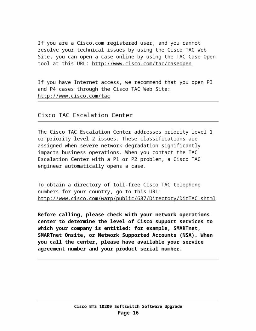
Jumpstarted with Solaris 10 OS. Staged with BTS 10200 Software Release 4.5.1 Installed EMS application software and databases
B. Two disk drives for EMS side B as a mirrored pair. The first disk is the primary disk and second disk is a mirrored disk. Disks should have: Jumpstarted with Solaris 10 OS Staged with BTS 10200 Software Release 4.5.1 Installed EMS application software and databases
C. Two disk drives for CA/FS side A as a mirrored pair. The first disk is the primary disk and second disk is a mirrored disk. Disks should have: Jumpstarted with Solaris 10 OS Staged with BTS 10200 Software Release 4.5.1 MR1
D. Two disk drives for CA/FS side B as a mirrored pair. The first disk is the primary disk and second disk is a mirrored disk. Disks should have:
Jumpstarted with Solaris 10 OS Staged with BTS 10200 Software Release 4.5.1 MR1
4. Locate CD-ROM Disc labeled as “BTS 10200 Application”
5. Locate CD-ROM Disc labeled as “BTS 10200 Database”
Cisco BTS 10200 Softswitch Software UpgradePage 19

6. Locate CD-ROM Disc labeled as “BTS 10200 Oracle Engine”
7. Locate CD-ROM Disc labeled as “BTS_04_05_01_V24_IP01”
8. There is secure shell (ssh) access to the Cisco BTS 10200 system.
9. There is console access to the Cisco BTS 10200 system.
10. Verify the target system to be upgraded has the latest 4.4.0 release deployed and the most recent patches applied if any. Please contact Cisco support if you are not sure what patch level the system is on.
11. A Network File Server (NFS) with at least 20 GB disk space is accessible from the Cisco BTS 10200 system to store system archives, backups, and configuration files.
12. H323_ENABLED Parameter:
a. If the parameter H323_ENABLED is set to “y” in opticall.cfg on 4.5.1, make sure that the following parameter returns TWO LOGICAL IP addresses.
DNS_FOR_CA146_H323_COM=h3a-SYS08CA146.ipclab.cisco.com
b. In case of fallback from 4.5.1 to 4.4.x make sure that the following parameter returns ONE LOGICAL IP address on 4.4.x
DNS_FOR_CA146_H323_COM=h3a-SYS08CA146.ipclab.cisco.com
.
Cisco BTS 10200 Softswitch Software UpgradePage 20

Chapter 3Complete one week before the scheduled upgrade
This chapter describes the tasks a user must complete one week before the scheduled upgrade.
Task 1: Add new domain names to DNS
This task must be performed on Domain Name Servers that are serving the Cisco BTS 10200 system.
The following three new 4.5.1 domain names are used to replace three 4.4.0 domain names used by existing 4.4.0 processes. Three 4.4.0 domain names return 4 Physical IP addresses. By changing the 4 physical IP with 2 floating logical IP, BTS will be seen as one single entity.
Step 1 Log in to Domain Name Servers for Cisco BTS 10200
Step 2 Add domain names for the following opticall.cfg parameters to Domain Name Server database where xxx – is the application instance number specific to the site.
DNS_FOR_CAxxx_SIM_COM
Note This is a qualified DNS name used by SIM process in Call Agent for LOCAL communication. Each name resolves to two logical IP addresses in the same subnet as the third virtual interface of management network(s). Each instance must have a unique DNS name and two uniquely associated LOGICAL IP addresses. They must NOT be the same as the domain names of POTS and ASM. (i.e. DNS_FOR_FSPTCxxx_POTS_COM and DNS_FOR_FSAINxxx_ASM_COM).
DNS_FOR_FSAINxxx_ASM_COM
Note This is a qualified DNS name used by ASM process in AIN Feature Server for LOCAL communication. Each name should return two logical IP addresses of AIN Feature Server which must be in the same subnet as the third virtual interface of management network(s). Each instance must have a unique DNS name and two uniquely associated LOGICAL IP addresses. They must NOT be the same as the domain names of SIM and POTS. (i.e. DNS_FOR_CAxxx_SIM_COM and DNS_FOR_FSPTCxxx_POTS_COM).
Cisco BTS 10200 Softswitch Software UpgradePage 21

DNS_FOR_FSPTCxxx_POTS_COM
Note This is fully qualified DNS name used by POTS process in Feature Server FSPTC for LOCAL communication. Each name should return two logical IP addresses of a POTS/CENTRIX Feature Server which match the subnet of the third virtual interface of management network(s). Each instance must have a unique DNS name and two uniquely associated LOGICAL IP addresses. They must NOT be the same as the domain names of SIM and ASM (i.e. DNS_FOR_CAxxx_SIM_COM and DNS_FOR_FSAINxxx_ASM_COM).
Task 2: Pre-construct opticall.cfg for the system to be upgraded to 4.5.1 MR1 release
Step 1 Get a copy of the completed Network Information Data Sheets (NIDS)
Step 2 Use following CCO link to the Cisco BTS 10200 NIDS Generator for Release 4.5 to generate the opticall.cfg file.
http://www.cisco.com/univercd/cc/td/doc/product/voice/bts10200/bts4_5/install/nids_45.xls
Note : Opticall.cfg generated from the 4.5.1 NIDS must be compared with the existing 4.4.0 opticall.cfg in the existing system.
Step 3 Place the file on the Network File Server (NFS)
Note New parameters added to the 4.5.1 release:
Where xxx – is the application instance number specific to the site.
NSCD_ENABLED CAxxx_LAF_PARAMETER
FSPTCxxx_LAF_PARAMETER
FSAINxxx_LAF_PARAMETER
EMS_LAF_PARAMETER
BDMS_LAF_PARAMETER
DNS_FOR_CAxxx_SIM_COM
DNS_FOR_FSAINxxx_ASM_COM
Cisco BTS 10200 Softswitch Software UpgradePage 22

DNS_FOR_FSPTCxxx_POTS_COM
SHARED_MEMORY_BACKUP_START_TIME_CA
SHARED_MEMORY_BACKUP_START_TIME_FSAIN
SHARED_MEMORY_BACKUP_START_TIME_FSPTC
SHARED_MEMORY_BACKUP_START_TIME_EMS
SHARED_MEMORY_BACKUP_START_TIME_BDMS
BILLING_FILENAME_TYPE
For further information and descriptions of the above parameters, please refer to opticall.cfg.
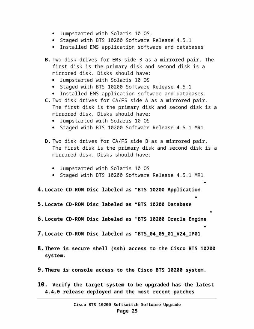
Task 3: Verify value of CA CONTROL PORT for IVR devices connected to BTS.
Note : The value of the CA_CONTROL_PORT for IVR devices connected to BTS should not be 0.
Note : IVR services may be interrupted during this task.
From Active EMS
Step 1 Login as “btsuser” User.
Step 2 Find the ANNC trunk-grp. The one with the main subscriber should be an IVR trunk-grp
CLI > show trunk_grp tg-type=ANNC;ID=80031CALL_AGENT_ID=CA146TG_TYPE=ANNCNUM_OF_TRUNKS=30TG_PROFILE_ID=ivr-ipunitySTATUS=INSDIRECTION=BOTH
Cisco BTS 10200 Softswitch Software UpgradePage 23

SEL_POLICY=ASCGLARE=SLAVEALT_ROUTE_ON_CONG=NSIGNAL_PORTED_NUMBER=NMAIN_SUB_ID=806-888-2000DEL_DIGITS=0TRAFFIC_TYPE=LOCALANI_BASED_ROUTING=NMGCP_PKG_TYPE=ANNC_CABLE_LABSANI_SCREENING=NSEND_RDN_AS_CPN=NSTATUS_MONITORING=NSEND_EARLY_BKWD_MSG=NEARLY_BKWD_MSG_TMR=5SCRIPT_SUPP=NVOICE_LAYER1_USERINFO=AUTOVOICE_INFO_TRANSFER_CAP=AUTOPERFORM_LNP_QUERY=N
Step 3: Ensure that subscriber CATEGORY is set to IVR.
CLI>show sub id=806-888-2000ID=806-888-2000CATEGORY=IVRNAME=tb06 806-888-2000STATUS=ACTIVEDN1=8068882000PRIVACY=NONERING_TYPE_DN1=1TGN_ID=80031PIC1=NONEPIC2=NONEPIC3=NONEGRP=NUSAGE_SENS=NSUB_PROFILE_ID=tb06-ivr-1TERM_TYPE=ROUTEPOLICY_ID=80031IMMEDIATE_RELEASE=NTERMINATING_IMMEDIATE_REL=NSEND_BDN_AS_CPN=NSEND_BDN_FOR_EMG=NSEND_BDN_AS_CPN=NSEND_BDN_FOR_EMG=NPORTED_IN=NBILLING_TYPE=NONE
Cisco BTS 10200 Softswitch Software UpgradePage 24
VMWI=YSDT_MWI=Y
Step 4: Use the trunk-grp id to find the trunks that have the IVR gateway ID
CLI>show trunk tgn-id=80031;ID=1TGN_ID=80031TERM_ID=ivr/1MGW_ID=ipunity-227-103
ID=2TGN_ID=80031TERM_ID=ivr/2MGW_ID=ipunity-227-103
ID=3TGN_ID=80031TERM_ID=ivr/3MGW_ID=ipunity-227-103
ID=4TGN_ID=80031TERM_ID=ivr/4MGW_ID=ipunity-227-103
ID=5TGN_ID=80031TERM_ID=ivr/5MGW_ID=ipunity-227-103
ID=6TGN_ID=80031TERM_ID=ivr/6MGW_ID=ipunity-227-103
Step 5: Show IVR Gateway to verify CALL_AGENT_CONTROL PORT value
CLI > show mgw id = ipunity-227-103ID=ipunity-227-13TSAP_ADDR=ms-ipunity.ipclab.cisco.comCALL_AGENT_ID=CA146MGW_PROFILE_ID=ivr-ipunitySTATUS=INSCALL_AGENT_CONTROL_PORT=0TYPE=TGW
Cisco BTS 10200 Softswitch Software UpgradePage 25

Reply : Success: Entry 1 of 1 returned.
Note: If the CALL_AGENT_CONTROL_PORT is set to 0 continue to step 6. If the value of the CALL_AGENT_CONTROL_PORT set to a value other than 0 like 2427 or 2428, do not execute further steps in this task.
Step 6: Control the IVR gateway to OOS state.
Note: Make sure that no calls exist on these trunks associated to the gateway.
CLI > status tt tgn-id=<IVR trunk-grp id>; cic=all.
80031 1 ADMIN_INS TERM_ACTIVE_IDLE ACTV IDLE NON_FAULTY80031 2 ADMIN_INS TERM_ACTIVE_IDLE ACTV IDLE NON_FAULTY80031 3 ADMIN_INS TERM_ACTIVE_IDLE ACTV IDLE NON_FAULTY
In the example output above note that the state of the endpoint/CIC is IDLE.
CLI>control mgw id=ipunity-227-103;mode=forced;target_state=oos;
MGW ID -> ipunity-227-103INITIAL STATE -> ADMIN_INS REQUEST STATE -> ADMIN_OOS RESULT STATE -> ADMIN_OOS FAIL REASON -> ADM found no failureREASON -> ADM executed successfullyRESULT -> ADM configure result in success
Step 7: Change the CALL_AGENT_CONTROL_PORT for the IVR gateway
CLI>change mgw id=ipunity-227-103;CALL_AGENT_CONTROL_PORT =2427
Step 8: Control the IVR gateway to the INS state.
CLI>control mgw id=ipunity-227-103;mode=forced;target_state=ins MGW ID -> ipunity-227-103INITIAL STATE -> ADMIN_OOS REQUEST STATE -> ADMIN_INS RESULT STATE -> ADMIN_INS FAIL REASON -> ADM found no failureREASON -> ADM executed successfullyRESULT -> ADM configure result in success
Cisco BTS 10200 Softswitch Software UpgradePage 26

Step 9: Control the trunk-termination for the IVR gateway to the INS state.
CLI>control tt tgn_id=80031;mode=forced;cic=all; target-state=insREQUEST STATE -> ADMIN_INS RESULT STATE -> ADMIN_INS FAIL REASON -> ADM found no failureREASON -> ADM executed successfullyRESULT -> ADM configure result in successTGN ID -> 80031CIC START -> 1CIC END -> 30
Step 10: Make sure the IVR trunk-terminations are in the INS state.
CLI>status tt tgn-id=80031;cic=all 80031 1 ADMIN_INS TERM_ACTIVE_IDLE ACTV IDLE NON_FAULTY 80031 2 ADMIN_INS TERM_ACTIVE_IDLE ACTV IDLE NON_FAULTY 80031 3 ADMIN_INS TERM_ACTIVE_IDLE ACTV IDLE NON_FAULTY 80031 4 ADMIN_INS TERM_ACTIVE_IDLE ACTV IDLE NON_FAULTY 80031 5 ADMIN_INS TERM_ACTIVE_IDLE ACTV IDLE NON_FAULTY 80031 6 ADMIN_INS TERM_ACTIVE_IDLE ACTV IDLE NON_FAULTY 80031 7 ADMIN_INS TERM_ACTIVE_IDLE ACTV IDLE NON_FAULTY 80031 8 ADMIN_INS TERM_ACTIVE_IDLE ACTV IDLE NON_FAULTY 80031 9 ADMIN_INS TERM_ACTIVE_IDLE ACTV IDLE NON_FAULTY
CLI > Exit
Task 4: Verify Default routes
Note : Verify that there are a total of 4 default routes on CA (including primary and secondary) and ensure that they are on the correct (signaling) VLANS. Issue the following command for CA (primary and secondary).
Cisco BTS 10200 Softswitch Software UpgradePage 27

<hostname># netstat –rn |grep default
Example output.
default 10.89.225.254 UG 1 1003default 10.89.226.254 UG 1 836
Caution: Call Processing application will not start, if there are other than 4 default routes or are not on the correct (signaling) VLANS.
Cisco BTS 10200 Softswitch Software UpgradePage 28

Chapter 4Complete the night before the scheduled upgrade
This chapter describes the tasks a user must complete the night before the scheduled upgrade.
If root access is disabled, to enable, please use Appendix L Task 1 to enable the root access.
CLI provisioning activity should be suspended before running the following pre-upgrade DB integrity checks. If any of these commands fail, please contact Cisco support.
Task 1: Check mlhg_terminal table
From Active EMS
Step 1 <hostname># su – oracle
Step 2 <hostname>$ sqlplus optiuser/optiuser
Step 3 sql> select term_id, mlhg_id, mgw_id from mlhg_terminal group by term_id,mlhg_id,mgw_id having count(*) > 1;
Please check:
Check for duplicated records with TERM_ID, MLHG_ID, MGW_ID If there is any record shown from the above query, remove the duplicated records
from CLI. Failure to do so will result in an upgrade failure.
Task 2: Check SLE table
Cisco BTS 10200 Softswitch Software UpgradePage 29
From Active EMS
Step 1 sql> select fname from sle where fname not in ('SCA','SCR','SCF','DRCW','NSA');
Please check:
If the above query returns any record, you either have to delete the sle record or upgrade the sle record with a valid fname from CLI. Failure to do so will result in an upgrade failure.
Task 3: Check Feature table
From Active EMS
Step 1 sql> select tid1, tid2, tid3 from feature where tid1 not in (select tid from trigger_id) or tid2 not in (select tid from trigger_id) or tid3 not in (select tid from trigger_id);
Please check:
If the above query returns any record, you either have to change or remove each feature record returned. Failure to do so will result in an upgrade failure.
Task 4: Check Feature table and Service-trigger table
From Active EMS
Step 1 From Oracle DB:
sql> select tid from service_trigger where tid not in (select tid from trigger_id);
Please check:
Cisco BTS 10200 Softswitch Software UpgradePage 30

If the above query returns any record, you either have to change or remove each service-trigger record returned. Failure to do so will result in an upgrade failure.
Step 2 Exit from Oracle:
sql> quit;
<hostname>$ exit
Step 3 Log in as “btsuser” user
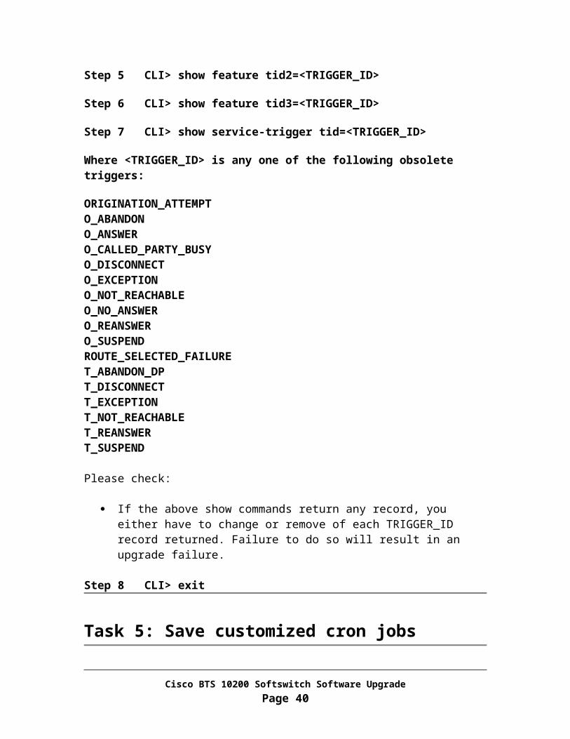
Step 4 CLI> show feature tid1=<TRIGGER_ID>
Step 5 CLI> show feature tid2=<TRIGGER_ID>
Step 6 CLI> show feature tid3=<TRIGGER_ID>
Step 7 CLI> show service-trigger tid=<TRIGGER_ID>
Where <TRIGGER_ID> is any one of the following obsolete triggers:
ORIGINATION_ATTEMPTO_ABANDONO_ANSWERO_CALLED_PARTY_BUSYO_DISCONNECTO_EXCEPTIONO_NOT_REACHABLEO_NO_ANSWERO_REANSWERO_SUSPENDROUTE_SELECTED_FAILURET_ABANDON_DPT_DISCONNECTT_EXCEPTIONT_NOT_REACHABLET_REANSWERT_SUSPEND
Please check:
If the above show commands return any record, you either have to change or remove of each TRIGGER_ID record returned. Failure to do so will result in an upgrade failure.
Step 8 CLI> exit
Cisco BTS 10200 Softswitch Software UpgradePage 31

Task 5: Save customized cron jobs
This upgrade process requires disk replacement. Because of this, all customized cron jobs in the system will be lost. Please save the cron jobs to your network file servers to be restored once the entire system is upgraded to the 4.5.1 MR1 release.
From Each BTS machine
Step 1 Log in as root user
Step 2 <hostname># cd /var/spool/cron/crontabs
Ftp each cron job to a Network File Server that the BTS system can access. .
Task 6 : Perform full database audit
This task verifies that provisioning is operational from CLI and a full database audit is performed and errors if any are corrected. Please refer to Appendix C to perform full data base Audit.
Note : Depending on the size of the database the audit could take multiple hours to complete. This task should be completed the night before the upgrade.
Cisco BTS 10200 Softswitch Software UpgradePage 32

Chapter 5Prepare System for Upgrade
This chapter describes the steps a user must complete the morning or the night before the scheduled upgrade.
If root access is disabled, to enable, please use Appendix L Task 1 to enable the root access.
Task 1: Verify System Status
Step 1 Verify that the side A systems are in the active state. Use Appendix A for this procedure.
Step 2 Verify that call processing is working without error. Use Appendix B for this procedure.
Task 2: Perform database row count audit (sanity check)
Step 1 In this task, you will perform database row count audit (sanity check) and correct any errors, if necessary.
Note: The database row count audit is a quick verification (sanity check) right before the upgrade that the number of rows match for tables in EMS and CA nodes.
Step 2 Login as “ciscouser”
Step 3 CLI> audit database type=row_count;
Cisco BTS 10200 Softswitch Software UpgradePage 33

Step 4 Check the audit report and verify there is no discrepancy or error. If errors are found, please try to correct them. If you are unable to correct, please contact Cisco Support.
Please follow the sample command provided below to correct the mismatches:
For the 4 handset provisioning tables (SLE, SC1D, SC2D, SUBSCRIBER-FEATURE-DATA), please use:
CLI> sync <table name> master=FSPTCyyy; target=EMS;
For all other tables, please use:
CLI> sync <table name> master=EMS; target=<CAxxx/FSPTCyyy/FSAINzzz>;
Task 3: Alarms.Verify that there are no outstanding major or critical alarms. Use Appendix D for this procedure.
Task 4: Oracle Database and Replication.Use Appendix E to verify that Oracle database and replication functions are working properly.
Caution Do not continue until the above verifications have been made. Call Cisco Support if you need assistance.
Task 5: Backup user account
The user accounts saved in this task is to be restored to side B EMS once it is upgraded to 4.5.1 release.
From EMS Side A
Step 1 Log in as root
Cisco BTS 10200 Softswitch Software UpgradePage 34

Step 2 Save the /opt/ems/users directory:
<hostname># mkdir –p /opt/.upgrade
<hostname># tar -cvf /opt/.upgrade/users.tar /opt/ems/users
Task 6: Verify and record Virtual IP (VIP) information
Verify if virtual IP is configured on the EMS machine. If VIP is configured, record the VIP, otherwise go to task 7. VIP will need to be re-configured after the upgrade procedure is complete.
From EMS Side A
Step 1 Log in as root user
Step 2 <hostname> su – btsadmin
Step 3 btsadmin> show ems
IP_ALIAS=10.89.224.177INTERFACE=eri0NTP_SERVER=10.89.224.44,
Step 4 Record the IP_ALIAS (VIP) and INTERFACE.
IP_ALIAS:
INTERFACE:
Step 5 btsadmin> exit
Task 7: Verify and record VSM Macro information
Verify if VSM Macros are configured on the EMS machine. If VSM is configured, record the VSM, otherwise go to chapter 6. VSM will need to be re-configured after the upgrade procedure is complete.
Cisco BTS 10200 Softswitch Software UpgradePage 35

From EMS Side A
Step 1 Log in as root user
Step 2 <hostname> su – btsadmin
Step 3 btsadmin> show macro id=VSM%
ID=VSMSubFeaturePARAMETERS=subscriber.id,subscriber.dn1,subscriber_service_profile.service-
id,service.fname1,service.fname2,service.fname3,service.fname4,service.fname5,service.fname6,service.fname7,service.fname8,service.fname9,service.fname10AND_RULES=subscriber.id=subscriber_service_profile.sub-id,subscriber_service_profile.service-id=service.id
Step 4 Record the VSM Macro information
Step 5 btsadmin> exit
Cisco BTS 10200 Softswitch Software UpgradePage 36

Chapter 6Upgrade Side B Systems
Task 1: Block provisioning path
It is critical to block unwanted provisioning traffics during upgrade. Please execute steps in Appendix J.
Task 2: Disable Oracle DB replication
From Active EMS
Step 1 Log in to Active EMS as “btsuser” user.
Step 2 CLI> control bdms id=BDMS01; target-state=forced-standby-active;
Step 3 CLI> control element-manager id=EM01; target-state=forced-standby-active;
Step 4 CLI session will terminate when application platform switchover is complete.
From EMS side A
Step 1 Log in as Oracle user:
<hostname># su – oracle
<hostname>$ cd /opt/oracle/admin/utl
Step 2 Set Oracle DB to simplex mode:
<hostname>$ rep_toggle –s optical1 –t set_simplex
Cisco BTS 10200 Softswitch Software UpgradePage 37

Answer “y” when prompt Answer “y” again when prompt
Step 3 <hostname>$ exit
Step 4 Restart applications to release Oracle connections:
<hostname># platform stop all
<hostname># platform start
Task 3: Force side A systems to active
This procedure will force the side A systems to remain active.
Note In the commands below, "xxx", "yyy" or "zzz" is the instance for the process on your system.
From Active EMS Side B
Step 1 Log in to Active EMS as “btsuser” user.
Step 2 CLI> control call-agent id=CAxxx; target-state=forced-active-standby;
Step 3 CLI> control feature-server id=FSPTCyyy; target-state=forced-active-standby;
Step 4 CLI> control feature-server id=FSAINzzz; target-state=forced-active-standby;
Step 5 CLI> control bdms id=BDMS01; target-state=forced-active-standby;
Step 6 CLI> control element-manager id=EM01; target-state=forced-active-standby;
Note : CLI session will terminate when application platform switchover is complete.
Cisco BTS 10200 Softswitch Software UpgradePage 38

Task 4: Inhibit EMS mate communication
In this task, you will isolate the OMS Hub on EMS side A from talking to EMS side B.
From EMS side A
Step 1 Log in as root
Step 2 <hostname># /opt/ems/utils/updMgr.sh –split_hub
Step 3 <hostname># nodestat
Verify there is no HUB communication from EMS side A to CA/FS side B Verify OMS Hub mate port status: No communication between EMS
Task 5: Stop applications and shutdown EMS side B
From EMS side B
Step 1 Log in as root
Step 2 Record the IP address and netmask for the management interface of the system.
For an example, if the “hme0” is used for management interface, then execute the following command:
<hostname># ifconfig hme0
Record the IP address and netmask for the interface to be used in the next task.
IP: _____________ Netmask: ____________ Interface Name: ___________
Step 3 <hostname># mv /etc/rc3.d/S99platform /etc/rc3.d/_S99platform
Step 4 <hostname># platform stop all
Step 5 <hostname># sync; sync
Step 6 <hostname># shutdown –i5 –g0 –y
Cisco BTS 10200 Softswitch Software UpgradePage 39
Task 6: Stop applications and shutdown CA/FS side B
From CA/FS side B
Step 1 Log in as root
Step 2 Record the IP address and netmask for the management interface of the system.
For an example, if the “hme0” is used for management interface, then execute the following command:
<hostname># ifconfig hme0
Record the IP address and netmask for the interface to be used in the next task.
IP: _____________ Netmask: ____________ Interface Name: ___________
Step 3 <hostname># mv /etc/rc3.d/S99platform /etc/rc3.d/_S99platform
Step 4 <hostname># platform stop all
Step 5 <hostname># sync; sync
Step 6 <hostname># shutdown –i5 –g0 –y
Task 7: Upgrade EMS side B to the new release
From EMS side B
Step 1 Power off the machine
Step 2 Remove disk0 from slot 0 off the machine and label it as “Release 4.4.0 EMS side B disk0”. Also remove disk1 from slot 1 off the machine and label it as “Release 4.4.0 EMS side B disk1”.
Replace 2 disks with two new disks mirrored.
Cisco BTS 10200 Softswitch Software UpgradePage 40

SunFire V440 disk slot lay out:
Disk 3 DVD-ROM
Disk 2
Disk 1
Disk 0 Sunfire 1280 disk slot lay out:
DVD-ROM
Disk 1
Disk 0
Step 3 Place new disk labeled as “Release 4.5.1 MR1 EMS side B disk0” in slot 0. Also place new disk labeled as “Release 4.5.1 MR1 EMS side B disk1” in slot 1.
Step 4 Power on the machine and allow the system to boot up by monitoring the boot process thru console
For a Sunfire 1280 machine, please execute the following command from console:
<lom>poweron
For other type of hardware, please use the power button to turn on the power.
Step 5 Log in as root thru console
Step 6 Remove network interface hardware configuration
<hostname># cp -fp /etc/path_to_inst /etc/path_to_inst.save
<hostname># \rm –f /etc/path_to_inst
<hostname># \rm –f /etc/path_to_inst.old
Step 7 Rebuild the hardware configuration
<hostname># reboot -- -r
Cisco BTS 10200 Softswitch Software UpgradePage 41

Wait for the system to boot up. Then log in as root.
Step 8 Restore management interface (recorded in Task 5):
<hostname># ifconfig <primary interface name> plumb
o Use Interface Name recorded in “Chapter 5, Task 4”
<hostname># ifconfig <primary interface name> <Interface IP> netmask <NETMASK> broadcast + up
o Use IP and NETMASK recorded in “Chapter 5, Task 4” Execute the following command to match the mode and speed on the bts
system and CAT switch interfaces.
o <hostname> # /etc/rc2.d/S68autoneg
If the system has IRDP enabled, please go to step 9, otherwise add static routes to reach Domain Name Server and Network File Server using “route add …” command:
o Example: route add -net 10.89.224.1 10.89.232.254
Where: 10.89.224.1 is the destination DNS server IP 10.89.232.254 is the gateway IP
Step 9 Reset ssh keys:
<hostname># \rm /.ssh/known_hosts
Step 10 sftp the opticall.cfg file from Network File Server (opticall.cfg was constructed in Chapter 3, Task 2) and place it under /etc directory.
Step 11 sftp resolv.conf file from Primary EMS Side A and place it under /etc directory.
<hostname># sftp <Side A EMS IP>sftp> lcd /etcsftp> cd /etcsftp> get resolv.confsftp> exit
Step 12 Run script program to replace the hostname
<hostname># cd /opt/ems/upgrade
Cisco BTS 10200 Softswitch Software UpgradePage 42

<hostname># DoTheChange -s
The system will prompt you for the root password of the mate, please enter it now.
The system will reboot when the script DoTheChange completes execution.
Please see Appendix K for the files handled by the script.
Step 13 Wait for the system to boot up. Then log in as root. At this point, ignore the warning message ‘could not find locale directory’ as the next steps would resolve it.
Step 14 Editing /etc/default/init with the proper time zone for the system:
<hostname># vi /etc/default/init
Remove lines and keep only the following lines:
#TZ=<Timezone>CMASK=022
For an example:
The original /etc/default/init file before line removal:
# @(#)init.dfl 1.5 99/05/26## This file is /etc/default/init. /etc/TIMEZONE is a symlink to this file.# This file looks like a shell script, but it is not. To maintain# compatibility with old versions of /etc/TIMEZONE, some shell constructs# (i.e., export commands) are allowed in this file, but are ignored.## Lines of this file should be of the form VAR=value, where VAR is one of# TZ, LANG, CMASK, or any of the LC_* environment variables.#TZ=US/CentralCMASK=022LC_COLLATE=en_US.ISO8859-1LC_CTYPE=en_US.ISO8859-1LC_MESSAGES=CLC_MONETARY=en_US.ISO8859-1LC_NUMERIC=en_US.ISO8859-1LC_TIME=en_US.ISO8859-1
The /etc/default/init file after line removal:
Cisco BTS 10200 Softswitch Software UpgradePage 43

# @(#)init.dfl 1.5 99/05/26## This file is /etc/default/init. /etc/TIMEZONE is a symlink to this file.# This file looks like a shell script, but it is not. To maintain# compatibility with old versions of /etc/TIMEZONE, some shell constructs# (i.e., export commands) are allowed in this file, but are ignored.## Lines of this file should be of the form VAR=value, where VAR is one of# TZ, LANG, CMASK, or any of the LC_* environment variables.#TZ=US/CentralCMASK=022
Step 15 Verify interface hardware configuration match to the host configuration. If not, you’ll need to change the interface pre-fix.
<hostname># egrep –i “qfe|ce|eri|bge|hme” /etc/path_to_inst
<hostname># ls –l /etc/hostname.*
If the interface names match from the above two outputs, please continue on to Step 16.
If the interface names do NOT match, please match them by changing the postfix of hostname.*.
For an example:
Output from “egrep –i “qfe|ce|eri|bge|hme” /etc/path_to_inst” is:
"/pci@1f,4000/network@1,1" 0 "hme""/pci@1f,4000/pci@4/SUNW,qfe@0,1" 0 "qfe""/pci@1f,4000/pci@4/SUNW,qfe@1,1" 1 "qfe""/pci@1f,4000/pci@4/SUNW,qfe@2,1" 2 "qfe""/pci@1f,4000/pci@4/SUNW,qfe@3,1" 3 "qfe"
Output from “ls -l /etc/hostname.*” is:
-rw-r--r-- 1 root other 14 May 16 16:03 /etc/hostname.hme0-rw-r--r-- 1 root other 14 May 16 16:04 /etc/hostname.hme0:1-rw-r--r-- 1 root other 14 May 16 16:04 /etc/hostname.eri0-rw-r--r-- 1 root other 14 May 16 16:04 /etc/hostname.eri0:1
After change, the output should be:
Cisco BTS 10200 Softswitch Software UpgradePage 44

-rw-r--r-- 1 root other 14 May 16 16:03 /etc/hostname.hme0-rw-r--r-- 1 root other 14 May 16 16:04 /etc/hostname.hme0:1-rw-r--r-- 1 root other 14 May 16 16:04 /etc/hostname.qfe0-rw-r--r-- 1 root other 14 May 16 16:04 /etc/hostname.qfe0:1
Step 16 Reboot the machine to pick up new TIMEZONE and interface setting:
<hostname># sync; sync; reboot
Wait for the system to boot up. Then log in as root.
Step 17 Install 4.5.1 V24 IP01 Patch. Refer to Appendix M, Install IP01 Patch on EMS.
Caution: 4.5.1 V24 IP01 is a mandatory patch and has to be installed at this step. Failure to install the IP01 patch at this step will impact the traffic and result in call failure.
Step 18 <hostname># /opt/ems/utils/updMgr.sh –split_hub
Step 19 <hostname># svcadm disable system/cron
Step 20 CDR delimiter customization is not retained after software upgrade. If this system has been customized, either the Customer or Cisco Support Engineer must manually customize again to keep the same customization.
<hostname># cd /opt/bdms/bin <hostname># vi platform.cfg
Find the section for the command argument list for the BMG process
Customize the CDR delimiters in the “Args=” line
Example:
Args=-port 15260 -h localhost -u optiuser -p optiuser -fmt default_formatter -UpdIntvl 3300 -ems_local_dn blg-aSYS14EMS.cisco.com -FD semicolon -RD linefeed
Step 21 <hostname># platform start –i oracle
Step 22 Log in as Oracle user.
<hostname># su – oracle
Cisco BTS 10200 Softswitch Software UpgradePage 45

<hostname>$ cd /opt/oracle/admin/utl
Step 23 Set Oracle DB to simplex mode:
<hostname>$ rep_toggle –s optical2 –t set_simplex
Answer “y” when prompt Answer “y” again when prompt
Step 24: <hostname> exit
Task 8: Upgrade CA/FS Side B to the new release
Warning Do not proceed if you don’t have a pre-constructed opticall.cfg file for the system. The opticall.cfg file should already be constructed in Chapter 3, Task 2.
From CA/FS side B
Step 1 Power off the machine
Step 2 Remove disk0 from slot 0 off the machine and label it as “Release 4.4.0 CA/FS side B disk0”. Also remove disk1 from slot 1 off the machine and label it as “Release 4.4.0 CA/FS side B disk1”.
Replace 2 disks with two new disks mirrored.
SunFire V440 disk slot lay out:
Disk 3 DVD-ROM
Disk 2
Disk 1
Disk 0 Sunfire 1280 disk slot lay out:
DVD-ROM
Cisco BTS 10200 Softswitch Software UpgradePage 46

Disk 1
Disk 0
Step 3 Place new disk labeled as “Release 4.5.1 MR1 CA/FS side B disk0” in slot 0. Also place new disk labeled as “Release 4.5.1 MR1 CA/FS side B disk1” in slot 1.
Step 4 Power on the machine and allow the system to boot up by monitoring the boot process thru console
For a Sunfire 1280 machine, please execute the following command from console:
<lom>poweron
For other type of hardware, please use the power button to turn on the power.
Step 5 Log in as root thru console
Step 6 Remove network interface hardware configuration
<hostname># cp -fp /etc/path_to_inst /etc/path_to_inst.save
<hostname># \rm –f /etc/path_to_inst
<hostname># \rm –f /etc/path_to_inst.old
Step 7 Rebuild the hardware configuration
<hostname># reboot -- -r
Wait for the system to boot up. Then log in as root.
Step 8 Restore management interface (recorded in Task 6):
<hostname># ifconfig <primary interface name> plumb
o Use Interface Name recorded in “Chapter 5, Task 5”
<hostname># ifconfig <primary interface name> <Interface IP> netmask <NETMASK> broadcast + up
o Use IP and NETMASK recorded in “Chapter 5, Task 5”
Cisco BTS 10200 Softswitch Software UpgradePage 47

Execute the following command to match the mode and speed on the bts system and CAT switch interfaces.
o <hostname> # /etc/rc2.d/S68autoneg
If the system has IRDP enabled, please go to step 9, otherwise add static routes to reach Domain Name Server and Network File Server using “route add …” command:
o Example: route add -net 10.89.224.1 10.89.232.254
Where: 10.89.224.1 is the destination DNS server IP 10.89.232.254 is the gateway IP
Step 9 Reset ssh keys:
<hostname># \rm /.ssh/known_hosts
Step 10 sftp the opticall.cfg file from Network File Server (opticall.cfg was constructed in Chapter 3, Task 2) and place it under /etc directory.
Step 11 sftp resolv.conf file from Primary CA/FS Side A and place it under /etc directory.
<hostname># sftp <Side A CA/FS IP>sftp> lcd /etcsftp> cd /etcsftp> get resolv.confsftp> exit
Step 12 Run script program to replace the hostname
<hostname># cd /opt/ems/upgrade
<hostname># DoTheChange -s
The system will prompt you for the root password of the mate, please enter it now.
The system will reboot when the script DoTheChange completes its run
Please see Appendix K for the files handled by the script.
Step 13 Wait for the system to boot up. Then log in as root. At this point, ignore the warning message ‘could not find locale directory’ as the next steps would resolve it.
Cisco BTS 10200 Softswitch Software UpgradePage 48

Step 14 Editing /etc/default/init with the proper time zone for the system:
<hostname># vi /etc/default/init
Remove lines and keep only the following lines:
#TZ=<Timezone>CMASK=022
For an example:
The original /etc/default/init file before line removal:
# @(#)init.dfl 1.5 99/05/26## This file is /etc/default/init. /etc/TIMEZONE is a symlink to this file.# This file looks like a shell script, but it is not. To maintain# compatibility with old versions of /etc/TIMEZONE, some shell constructs# (i.e., export commands) are allowed in this file, but are ignored.## Lines of this file should be of the form VAR=value, where VAR is one of# TZ, LANG, CMASK, or any of the LC_* environment variables.#TZ=US/CentralCMASK=022LC_COLLATE=en_US.ISO8859-1LC_CTYPE=en_US.ISO8859-1LC_MESSAGES=CLC_MONETARY=en_US.ISO8859-1LC_NUMERIC=en_US.ISO8859-1LC_TIME=en_US.ISO8859-1
The /etc/default/init file after line removal:
# @(#)init.dfl 1.5 99/05/26## This file is /etc/default/init. /etc/TIMEZONE is a symlink to this file.# This file looks like a shell script, but it is not. To maintain# compatibility with old versions of /etc/TIMEZONE, some shell constructs# (i.e., export commands) are allowed in this file, but are ignored.## Lines of this file should be of the form VAR=value, where VAR is one of# TZ, LANG, CMASK, or any of the LC_* environment variables.#
Cisco BTS 10200 Softswitch Software UpgradePage 49

TZ=US/CentralCMASK=022
Step 15 Verify interface hardware configuration match to the host configuration. If not, you’ll need to change the interface pre-fix.
<hostname># egrep –i “qfe|ce|eri|bge|hme” /etc/path_to_inst
<hostname># ls –l /etc/hostname.*
If the interface names match from the above two outputs, please continue on Step 16.
If the interface names do NOT match, please match them by changing the postfix of hostname.*.
For an example:
Output from “egrep –i “qfe|ce|eri|bge|hme” /etc/path_to_inst” is:
"/pci@1f,4000/network@1,1" 0 "hme""/pci@1f,4000/pci@4/SUNW,qfe@0,1" 0 "qfe""/pci@1f,4000/pci@4/SUNW,qfe@1,1" 1 "qfe""/pci@1f,4000/pci@4/SUNW,qfe@2,1" 2 "qfe""/pci@1f,4000/pci@4/SUNW,qfe@3,1" 3 "qfe""/pci@1f,2000/pci@1/SUNW,qfe@0,1" 4 "qfe""/pci@1f,2000/pci@1/SUNW,qfe@1,1" 5 "qfe""/pci@1f,2000/pci@1/SUNW,qfe@2,1" 6 "qfe""/pci@1f,2000/pci@1/SUNW,qfe@3,1" 7 "qfe"
Output from “ls -l /etc/hostname.*” is:
-rw-r--r-- 1 root other 14 Jun 10 11:25 hostname.hme0-rw-r--r-- 1 root other 14 Jun 10 11:25 hostname.eri0-rw-r--r-- 1 root other 13 Jun 10 11:25 hostname.eri1-rw-r--r-- 1 root other 13 Jun 10 11:25 hostname.eri1:1-rw-r--r-- 1 root other 14 Jun 10 11:25 hostname.eri1:2-rw-r--r-- 1 root other 12 Jun 10 11:25 hostname.eri1:3-rw-r--r-- 1 root other 13 Jun 10 11:25 hostname.eri2-rw-r--r-- 1 root other 13 Jun 10 11:25 hostname.eri2:1-rw-r--r-- 1 root other 14 Jun 10 11:25 hostname.eri2:2-rw-r--r-- 1 root other 12 Jun 10 11:25 hostname.eri2:3
After change, the output should be:
Cisco BTS 10200 Softswitch Software UpgradePage 50

-rw-r--r-- 1 root other 14 Jun 10 11:25 hostname.hme0-rw-r--r-- 1 root other 14 Jun 10 11:25 hostname.qfe0-rw-r--r-- 1 root other 13 Jun 10 11:25 hostname.qfe1-rw-r--r-- 1 root other 13 Jun 10 11:25 hostname.qfe1:1-rw-r--r-- 1 root other 14 Jun 10 11:25 hostname.qfe1:2-rw-r--r-- 1 root other 12 Jun 10 11:25 hostname.qfe1:3-rw-r--r-- 1 root other 13 Jun 10 11:25 hostname.qfe2-rw-r--r-- 1 root other 13 Jun 10 11:25 hostname.qfe2:1-rw-r--r-- 1 root other 14 Jun 10 11:25 hostname.qfe2:2-rw-r--r-- 1 root other 12 Jun 10 11:25 hostname.qfe2:3
Step 16 Reboot the machine to pick up new TIMEZONE and interface setting:
<hostname># sync; sync; reboot
Wait for the system to boot up. Then log in as root.
Step 17 Check for configuration errors
<hostname># cd /opt/Build
<hostname># checkCFG –u
Correct errors generated by checkCFG Once the result is clean without errors, then proceed to the next step.
Step 18 <hostname># install.sh -upgrade
Step 19 Answer "y" when prompted. This process will take up to 15 minutes to complete.
Some of the OS patch installation requires immediate system reboot. If system is rebooted because of the OS patch installation, you must re-run “install.sh -upgrade” after system boots up. Fail to do so will result in installation failure.
When installation is completed, answer "y" if prompted for reboot.
Wait for the system to boot up. Then log in as root..
Step 20 Install 4.5.1 V24 IP01 Patch. Refer to Appendix N, Install IP01 Patch on CA.
Caution: 4.5.1 V24 IP01 is a mandatory patch and has to be installed at this step. Failure to install the IP01 patch at this step will impact the traffic and result in call failure.
Cisco BTS 10200 Softswitch Software UpgradePage 51

Step 21 <hostname># platform start
Step 22 <hostname># mv /etc/rc3.d/_S99platform /etc/rc3.d/S99platform
Task 9: Migrate oracle data
The subscriber data migration breaks into two parts: Oracle DB -- data migration rules are defined in the configuration file
/opt/oracle/admin/upd/config/4.4.0_to_4.5.1.cfg. Java process DMMgr reads in rules and then reads data from mate EMS Oracle DB thru DB connection established by the Java process.
Shared Memory DB for Call Agent/Feature Server -- data is replicated thru RDM and utilizes DBM checkpoint library to move data from an old release to a new release.
From EMS side B
Step 1 Copying data.
<hostname>$ su - oracle
<hostname>$ cd /opt/oracle/admin/upd
<hostname>$ java dba.dmt.DMMgr -upgrade -auto ./config/4.4.0_to_4.5.1.cfg
Step 2 Verify the data migration is a success.
<hostname>$ echo $?
Verify the returned value is 0. If not, please sftp /opt/oracle/admin/upd/DMMgr.log file off system and call
for immediate technical assistance.
Step 3 <hostname>$ java dba.adm.DBUsage -sync
Verify Number of tables “unable-to-sync” is 0 If not, please contract Cisco support
Step 4 <hostname>$ cd /opt/oracle/opticall/create
Cisco BTS 10200 Softswitch Software UpgradePage 52

Step 5 <hostname>$ dbinstall optical2 -load dbsize
Step 6 <hostname>$ exit
Step 7 Enable daemon manager:
<hostname># /opt/ems/bin/daemon_mgr.sh add
<hostname># /opt/ems/bin/daemon_mgr.sh start
Step 8 <hostname># platform start
Step 9 <hostname># svcadm enable system/cron
Step 10 <hostname># mv /etc/rc3.d/_S99platform /etc/rc3.d/S99platform
Cisco BTS 10200 Softswitch Software UpgradePage 53

Chapter 7Prepare Side A Systems for Upgrade
Task 1: Force side A systems to standby
This procedure will force the side A systems to standby and force the side B systems to active.
Note In the commands below, "xxx", "yyy" or "zzz" is the instance for the process on your system.
From EMS side A
Step 1 Log in as “btsuser” user
Step 2 CLI> control call-agent id=CAxxx; target-state=forced-standby-active;
Step 3 CLI> control feature-server id=FSPTCyyy; target-state=forced-standby-active;
Step 4 CLI> control feature-server id=FSAINzzz; target-state=forced-standby-active;
Step 5 CLI> control bdms id=BDMS01; target-state=forced-standby-active;
Step 6 CLI> control element-manager id=EM01; target-state=forced-standby-active;
Step 7 Depending on the CLI user type, the CLI session may terminate upon successful completion of last CLI command.
Note If the system fails to switchover from side A to side B, please contact Cisco Support to determine whether the system should fallback. If fallback is needed, please following Appendix F.
Cisco BTS 10200 Softswitch Software UpgradePage 54

Task 2: Check and Correct Feature Server and Call Agent TSAP address
From EMS side B
Step 1 Log in to EMS side B as “btsuser” user.
Step 2 Check TSAP_ADDR token for AIN , POTS feature server and CA and make sure that they match with the ones populated in opticall.cfg.
Example 1
In Opticall.cfg the following entry is populated as follows
DNS_FOR_FSAIN205_ASM_COM=asm-SYS76AIN205.ipclab.cisco.com
The corresponding FSAIN feature server TSAP_ADDR token should be as indicated below.
Btsuser > show feature_server ID=FSAIN205TSAP_ADDR=asm-SYS76AIN205.ipclab.cisco.com:11205TYPE=AINEXTERNAL_FEATURE_SERVER=N
Example 2
In Opticall.cfg the following entry is populated as follows
DNS_FOR_FSPTC235_POTS_COM=pots-SYS76PTC235.ipclab.cisco.com
The corresponding POTS feature server TSAP_ADDR token should be as indicated below.
Btsuser > show_feature_serverID=POTS TSAP_ADDR= pots-SYS76PTC235.ipclab.cisco.com:11235 TYPE=POTSEXTERNAL_FEATURE_SERVER=N
Example 3
Cisco BTS 10200 Softswitch Software UpgradePage 55

In Opticall.cfg the following entry is populated as follows
DNS_FOR_CA146_SIM_COM=sim-SYS76CA146.ipclab.cisco.com
The corresponding Call Agent TSAP_ADDR token should be as indicated below.
Btsuser > show_call agentID=CA146TSAP_ADDR= sim-SYS76CA146.ipclab.cisco.com:9146MGW_MONITORING_ENABLED=Y
NOTE : Make sure that TSAP_ADDR token is provisioned correctly for Call Agent, AIN and POTS feature servers
If not, please use the change command to correct the TSAP_ADDR token:
CLI> change feature-server id=<FS ID>; TSAP_ADDR=<dn:port>;
CLI > change call agent id = <Call Agent ID> ;TSAP ADDR =<dn:port>;
Step 3 Check TSAP port number for both AIN and POTS feature servers:
CLI> show feature-server;
Sample output:
ID=FSAIN205TSAP_ADDR=asm-SYS36AIN205.ipclab.cisco.com:11205TYPE=AINEXTERNAL_FEATURE_SERVER=N
ID=FSPTC235TSAP_ADDR=pots-SYS36PTC235.ipclab.cisco.com:11235TYPE=POTSEXTERNAL_FEATURE_SERVER=N
Make sure the port number provisioned is:
o AIN Feature Server: 11205o POTS Feature Server: 11235
If not, please use the change command:
CLI> change feature-server id=<FS ID>; TSAP_ADDR=<dn:port>;
Cisco BTS 10200 Softswitch Software UpgradePage 56

Step 4 CLI> exit
Task 3: Sync Data from EMS side B to CA/FS side B
In this task, you will sync from EMS to CA/FS for several inter-platform migrated tables.
From EMS side B
Step 1 Log in as ciscouser (password: ciscosupport)
Step 2 CLI> sync emergency_number_list master=EMS; target=CAxxx;
Step 3 CLI> sync radius-profile master=EMS; target=FSPTCyyy;
Step 4 CLI> sync lnp-profile master=EMS; target=CAxxx;
Step 5 CLI> sync lnp-profile master=EMS; target=FSAINzzz;
Step 6 CLI> sync subsystem_grp master=EMS; target=FSPTCyyy;
Step 7 CLI> sync subsystem_grp master=EMS; target=FSAINzzz;
Step 8 CLI> sync pop master=EMS; target=CAxxx;
Step 9 CLI> sync pop master=EMS; target=FSPTCyyy;
Step 10 CLI> sync pop master=EMS; target=FSAINzzz;
Step 11 CLI> exit
Task 4: Block Provisioning Path
From EMS side B
Make sure the provisioning path is blocked.
Step 1 Login as root
Step 2 Disable bulk provisioning:
Cisco BTS 10200 Softswitch Software UpgradePage 57

<hostname># cd /opt/ems/bin
<hostname># echo "update PlatformPrograms set enable='N' where id='DLP';" | mysql_cli.sh
<hostname># pkill smg
Task 5: Validate release 4.5.1 MR1 software operation
To verify the stability of the newly installed 4.5.1 MR1 Release, let CA/FS side B carry live traffic for period of time. Monitor the Cisco BTS 10200 Softswitch and the network. If there are any problems, please investigate and contact Cisco Support if necessary.
This activity should NOT last more than an hour. The tasks should include: Basic call on-net to on-net, and on-net to off-net calls Pre-existed feature calls Verify billing CDR for calls made
From EMS side B
Step 1 Verify that call processing using Appendix B.
Step 2 Log in as “ciscouser” user.
Step 3 CLI> audit database type=row-count;
Please ignore mismatches for the following north bound traffic tables:o SLE
o SC1D
o SC2D
o SUBSCRIBER-FEATURE-DATA
Please check the report to any mismatched tables.
If any table shows mis-match, sync the table from EMS to CA/FS, then perform a detailed audit on each mismatched table:
Cisco BTS 10200 Softswitch Software UpgradePage 58

CLI> sync <table name> master=EMS; target=<CA/FSPTC|FSAIN>;
CLI> audit <table name>;
Step 4 Verify the SUP config is set up correctly
CLI> show sup-config; Verify refresh rate is set to 86400.
If not, do the following
CLI> change sup-config type=refresh_rate; value=86400;
CLI> exit
Task 6: Ftp billing records off the system
From EMS side A
Step 1 Log in as root
Step 2 <hostname># ls /opt/bms/ftp/billing
If there are files listed, then SFTP the files to a mediation device on the network and remove the files from the /opt/bms/ftp/billing directory.
Note Once the system proves stable and you decide to move ahead with the upgrade, then you must execute subsequent tasks. If fallback is needed at this stage, please follow the fallback procedure in Appendix F.
Cisco BTS 10200 Softswitch Software UpgradePage 59

Chapter 8Upgrade Side A Systems
Task 1: Stop applications and shutdown EMS side A
From EMS side A
Step 1 Log in as root
Step 2 Record the IP address and netmask for the management interface of the system.
For an example, if the “hme0” is used for management interface, then execute the following command:
<hostname># ifconfig hme0
Record the IP address and netmask for the interface to be used in the next task.
IP: _____________ Netmask: ____________ Interface Name: ___________
Step 3 <hostname># mv /etc/rc3.d/S99platform /etc/rc3.d/_S99platform
Step 4 <hostname># platform stop all
Step 5 <hostname># sync; sync
Step 6 <hostname># shutdown –i5 –g0 –y
Task 2: Stop applications and shutdown CA/FS side A
From CA/FS side A
Step 1 Log in as root
Cisco BTS 10200 Softswitch Software UpgradePage 60

Step 2 Record the IP address and netmask for the management interface of the system.
For an example, if the “hme0” is used for management interface, then execute the following command:
<hostname># ifconfig hme0
Record the IP address and netmask for the interface to be used in the next task.
IP: _____________ Netmask: ____________ Interface Name: ___________
Step 3 <hostname># mv /etc/rc3.d/S99platform /etc/rc3.d/_S99platform
Step 4 <hostname># platform stop all
Step 5 <hostname># sync; sync
Step 6 <hostname># shutdown –i5 –g0 –y
Task 3: Upgrade EMS side A to the new release
From EMS side A
Step 1 Power off the machine
Step 2 Remove disk0 from slot 0 off the machine and label it as “Release 4.4.0 EMS side A disk0”. Also remove disk1 from slot 1 off the machine and label it as “Release 4.4.0 EMS side A disk1”.
Replace 2 disks with two new disks mirrored.
SunFire V440 disk slot lay out:
Disk 3 DVD-ROM
Disk 2
Disk 1
Disk 0 Sunfire 1280 disk slot lay out:
Cisco BTS 10200 Softswitch Software UpgradePage 61

DVD-ROM
Disk 1
Disk 0
Step 3 Place new disk labeled as “Release 4.5.1 MR1 EMS side A disk0” in slot 0. Also place new disk labeled as “Release 4.5.1 MR1 EMS side A disk1” in slot 1.
Step 4 Power on the machine and allow the system to boot up by monitoring the boot process thru console
For a Sunfire 1280 machine, please execute the following command from console:
<lom>poweron
For other type of hardware, please use the power button to turn on the power.
Step 5 Log in as root thru console
Step 6 Remove network interface hardware configuration
<hostname># cp -fp /etc/path_to_inst /etc/path_to_inst.save
<hostname># \rm –f /etc/path_to_inst
<hostname># \rm –f /etc/path_to_inst.old
Step 7 Rebuild the hardware configuration
<hostname># reboot -- -r
Wait for the system to boot up. Then log in as root.
Step 8 Restore management interface (recorded in Task 1):
<hostname># ifconfig <primary interface name> plumb
o Use Interface Name recorded in “Chapter 7, Task 1”
<hostname># ifconfig <primary interface name> <Interface IP> netmask <NETMASK> broadcast + up
Cisco BTS 10200 Softswitch Software UpgradePage 62

o Use IP and NETMASK recorded in “Chapter 7, Task 1”
Execute the following command to match the mode and speed on the bts system and CAT switch interfaces.
o <hostname> # /etc/rc2.d/S68autoneg
If the system has IRDP enabled, please go to step 9, otherwise add static routes to reach Domain Name Server and Network File Server using “route add …” command:
o Example: route add -net 10.89.224.1 10.89.232.254
Where: 10.89.224.1 is the destination DNS server IP 10.89.232.254 is the gateway IP
Step 9 Reset ssh keys:
<hostname># \rm /.ssh/known_hosts
Step 10 sftp the opticall.cfg and resolv.conf from Secondary EMS side B and place it under /etc directory.
<hostname># sftp <Side B EMS IP>sftp> lcd /etcsftp> cd /etcsftp> get resolv.confsftp> get opticall.cfgsftp> exit
Step 11 Run script program to replace the hostname
<hostname># cd /opt/ems/upgrade
<hostname># DoTheChange -p
The system will prompt you for the root password of the mate, please enter it now.
The system will reboot when the script DoTheChange completes its run
Please see Appendix K for the files handled by the script.
Step 12 Wait for the system to boot up. Then Log in as root. At this point, ignore the warning message ‘could not find locale directory’ as the next steps would resolve it.
Cisco BTS 10200 Softswitch Software UpgradePage 63

Step 13 Verify interface hardware configuration to match the host configuration. If not, you’ll need to change the interface pre-fix.
<hostname># egrep –i “qfe|ce|eri|bge|hme” /etc/path_to_inst
<hostname># ls –l /etc/hostname.*
If the interface names match from the above two outputs, please continue on Step 15.
If the interface names do NOT match, please match them by changing the postfix of hostname.*.
For an example:
Output from “egrep –i “qfe|ce|eri|bge|hme” /etc/path_to_inst” is:
"/pci@1f,4000/network@1,1" 0 "hme""/pci@1f,4000/pci@4/SUNW,qfe@0,1" 0 "qfe""/pci@1f,4000/pci@4/SUNW,qfe@1,1" 1 "qfe""/pci@1f,4000/pci@4/SUNW,qfe@2,1" 2 "qfe""/pci@1f,4000/pci@4/SUNW,qfe@3,1" 3 "qfe"
Output from “ls -l /etc/hostname.*” is:
-rw-r--r-- 1 root other 14 May 16 16:03 /etc/hostname.hme0-rw-r--r-- 1 root other 14 May 16 16:04 /etc/hostname.hme0:1-rw-r--r-- 1 root other 14 May 16 16:04 /etc/hostname.eri0-rw-r--r-- 1 root other 14 May 16 16:04 /etc/hostname.eri0:1
After change, the output should be:
-rw-r--r-- 1 root other 14 May 16 16:03 /etc/hostname.hme0-rw-r--r-- 1 root other 14 May 16 16:04 /etc/hostname.hme0:1-rw-r--r-- 1 root other 14 May 16 16:04 /etc/hostname.qfe0-rw-r--r-- 1 root other 14 May 16 16:04 /etc/hostname.qfe0:1
Step 14 Reboot the machine to pick up new interface setting:
<hostname># sync; sync; reboot
Wait for the system to boot up. Then log in as root.
Step 15 Install 4.5.1 V24 IP01 Patch. Refer to Appendix M, Install IP01 Patch on EMS.
Cisco BTS 10200 Softswitch Software UpgradePage 64

Caution: Caution: 4.5.1V24 IP01 is a mandatory patch and has to be installed at this step. Failure to install the IP01 patch at this step will impact the traffic, and result in call failures.
Step 15 CDR delimiter customization is not retained after software upgrade. If this system has been customized, either the Customer or Cisco Support Engineer must manually customize again to keep the same customization.
<hostname># cd /opt/bdms/bin <hostname># vi platform.cfg
Find the section for the command argument list for the BMG process
Customize the CDR delimiters in the “Args=” line
Example:
Args=-port 15260 -h localhost -u optiuser -p optiuser -fmt default_formatter -UpdIntvl 3300 -ems_local_dn blg-aSYS14EMS.cisco.com -FD semicolon -RD linefeed
Task 4: Upgrade CA/FS Side A to the new release
From CA/FS side A
Step 1 Power off the machine
Step 2 Remove disk0 from slot 0 off the machine and label it as “Release 4.4.0 CA/FS side A disk0”. Also remove disk1 from slot 1 off the machine and label it as “Release 4.4.0 CA/FS side A disk1”.
Replace 2 disks with two new disks mirrored.
SunFire V440 disk slot lay out:
Disk 3 DVD-ROM
Disk 2
Disk 1
Disk 0
Cisco BTS 10200 Softswitch Software UpgradePage 65

Sunfire 1280 disk slot lay out:
DVD-ROM
Disk 1
Disk 0
Step 3 Place new disk labeled as “Release 4.5.1 MR1 CA/FS side A disk0” in slot 0. Also place new disk labeled as “Release 4.5.1 MR1 CA/FS side A disk1” in slot 1.
Step 4 Power on the machine and allow the system to boot up by monitoring the boot process thru console
For a Sunfire 1280 machine, please execute the following command from console:
<lom>poweron
For other type of hardware, please use the power button to turn on the power.
Step 5 Log in as root thru console
Step 6 Remove network interface hardware configuration
<hostname># cp -fp /etc/path_to_inst /etc/path_to_inst.save
<hostname># \rm –f /etc/path_to_inst
<hostname># \rm –f /etc/path_to_inst.old
Step 7 Rebuild the hardware configuration
<hostname># reboot -- -r
Wait for the system to boot up. Then log in as root.
Step 8 Restore management interface (recorded in Task 2):
<hostname># ifconfig <interface name> plumb
o Use Interface Name recorded in “Chapter 7, Task 2”
Cisco BTS 10200 Softswitch Software UpgradePage 66

<hostname># ifconfig <interface name> <Interface IP> netmask <NETMASK> broadcast + up
o Use IP and NETMASK recorded in “Chapter 7, Task 2” Execute the following command to match the mode and speed on the bts
system and CAT switch interfaces.
o <hostname> # /etc/rc2.d/S68autoneg
If the system has IRDP enabled, please go to step 9, otherwise add static routes to reach Domain Name Server and Network File Server using “route add …” command:
o Example: route add -net 10.89.224.1 10.89.232.254
Where: 10.89.224.1 is the destination DNS server IP 10.89.232.254 is the gateway IP
Step 9 Reset ssh keys:
<hostname># \rm /.ssh/known_hosts
Step 10 sftp the opticall.cfg and resolv.conf from Secondary CA/FS side B and place it under /etc directory.
<hostname># sftp <Side B CA/FS IP>sftp> lcd /etcsftp> cd /etcsftp> get resolv.confsftp> get opticall.cfgsftp> exit
Step 11 Run script program to replace the hostname
<hostname># cd /opt/ems/upgrade
<hostname># DoTheChange -p
The system will prompt you for the root password of the mate, please enter it now.
The system will reboot when the script DoTheChange completes its run
Please see Appendix K for the files handled by the script.
Cisco BTS 10200 Softswitch Software UpgradePage 67

Step 12 Wait for the system to boot up. Then Log in as root. At this point, ignore the warning message ‘could not find locale directory’ as the next steps would resolve it.
Step 13 Verify interface hardware configuration match to the host configuration. If not, you’ll need to change the interface pre-fix.
<hostname># egrep –i “qfe|ce|eri|bge|hme” /etc/path_to_inst
<hostname># ls –l /etc/hostname.*
If the interface names match from the above two outputs, please continue on Step 15.
If the interface names do NOT match, please match them by changing the postfix of hostname.*.
For an example:
Output from “egrep –i “qfe|ce|eri|bge|hme” /etc/path_to_inst” is:
"/pci@1f,4000/network@1,1" 0 "hme""/pci@1f,4000/pci@4/SUNW,qfe@0,1" 0 "qfe""/pci@1f,4000/pci@4/SUNW,qfe@1,1" 1 "qfe""/pci@1f,4000/pci@4/SUNW,qfe@2,1" 2 "qfe""/pci@1f,4000/pci@4/SUNW,qfe@3,1" 3 "qfe""/pci@1f,2000/pci@1/SUNW,qfe@0,1" 4 "qfe""/pci@1f,2000/pci@1/SUNW,qfe@1,1" 5 "qfe""/pci@1f,2000/pci@1/SUNW,qfe@2,1" 6 "qfe""/pci@1f,2000/pci@1/SUNW,qfe@3,1" 7 "qfe"
Output from “ls -l /etc/hostname.*” is:
-rw-r--r-- 1 root other 14 Jun 10 11:25 hostname.hme0-rw-r--r-- 1 root other 14 Jun 10 11:25 hostname.eri0-rw-r--r-- 1 root other 13 Jun 10 11:25 hostname.eri1-rw-r--r-- 1 root other 13 Jun 10 11:25 hostname.eri1:1-rw-r--r-- 1 root other 14 Jun 10 11:25 hostname.eri1:2-rw-r--r-- 1 root other 12 Jun 10 11:25 hostname.eri1:3-rw-r--r-- 1 root other 13 Jun 10 11:25 hostname.eri2-rw-r--r-- 1 root other 13 Jun 10 11:25 hostname.eri2:1-rw-r--r-- 1 root other 14 Jun 10 11:25 hostname.eri2:2-rw-r--r-- 1 root other 12 Jun 10 11:25 hostname.eri2:3
After change, the output should be:
Cisco BTS 10200 Softswitch Software UpgradePage 68

-rw-r--r-- 1 root other 14 Jun 10 11:25 hostname.hme0-rw-r--r-- 1 root other 14 Jun 10 11:25 hostname.qfe0-rw-r--r-- 1 root other 13 Jun 10 11:25 hostname.qfe1-rw-r--r-- 1 root other 13 Jun 10 11:25 hostname.qfe1:1-rw-r--r-- 1 root other 14 Jun 10 11:25 hostname.qfe1:2-rw-r--r-- 1 root other 12 Jun 10 11:25 hostname.qfe1:3-rw-r--r-- 1 root other 13 Jun 10 11:25 hostname.qfe2-rw-r--r-- 1 root other 13 Jun 10 11:25 hostname.qfe2:1-rw-r--r-- 1 root other 14 Jun 10 11:25 hostname.qfe2:2-rw-r--r-- 1 root other 12 Jun 10 11:25 hostname.qfe2:3
Step 14 Reboot the machine to pick up new interface setting:
<hostname># sync; sync; reboot
Wait for the system to boot up. Then log in as root.
Step 15 Install the applications
<hostname># cd /opt/Build
<hostname># install.sh –upgrade
Step 16 Answer "y" when prompted. This process will take up to 15 minutes to complete.
Some of the OS patch installation requires immediate system reboot. If system is rebooted because of the OS patch installation, you must re-run “install.sh -upgrade” after system boots up. Fail to do so will result in installation failure.
When installation is completed, answer "y" if prompted for reboot.
Wait for the system to boot up. Then Log in as root.
Step 17 Install 4.5.1 V24 IP01 Patch. Refer to Appendix N , Install IP01 Patch on CA.
Caution: 4.5.1V24 IP01 patch is a mandatory patch and has to be installed at this step. Failure to install the IP01 patch at this step will impact the traffic and result in call failures.
Step 17 <hostname># platform start
Step 18 <hostname># mv /etc/rc3.d/_S99platform /etc/rc3.d/S99platform
Cisco BTS 10200 Softswitch Software UpgradePage 69

Task 5: Restore Hub communication
From EMS side B
Step 1 Log in as root
Step 2 <hostname># /opt/ems/utils/updMgr.sh –restore_hub
Step 3 Verify hub communication on EMS Side B
<hostname># nodestat
Task 6: Copying oracle data
From EMS side A
Step 1 Log in as root
Step 2 <hostname># svcadm disable system/cron
Step 3 <hostname># platform start –i oracle
Step 4 Copying data.
<hostname>$ su – oracle
<hostname>$ cd /opt/oracle/admin/upd
<hostname>$ java dba.dmt.DMMgr –copy -auto
Step 5 Verify the data copy is a success.
<hostname>$ echo $?
Verify the returned value is 0. If not, please sftp /opt/oracle/admin/upd/DMMgr.log file off system and call
for immediate technical assistance.
<hostname>$ exit
Cisco BTS 10200 Softswitch Software UpgradePage 70

Step 6 Enable daemon manager:
<hostname># /opt/ems/bin/daemon_mgr.sh add
<hostname># /opt/ems/bin/daemon_mgr.sh start
Step 7 <hostname># platform start
Step 8 <hostname># svcadm enable system/cron
Step 9 <hostname># mv /etc/rc3.d/_S99platform /etc/rc3.d/S99platform
Task 7: Verify Hub communication
From EMS side B
Step 1 Log in as root
Step 2 <hostname># nodestat
Verify OMS Hub mate port status is established Verify HUB communication from EMS side B to CA/FS side A is established
Cisco BTS 10200 Softswitch Software UpgradePage 71

Chapter 9Finalizing Upgrade
Task 1: Switchover activity from side B to side A
This procedure will force the active system activity from side B to side A.
From EMS side B
Note In the commands below, "xxx", "yyy" or "zzz" is the instance for the process on your system.
Step 1 Log in to EMS side B as “btsuser” user.
Step 2 CLI> control call-agent id=CAxxx; target-state=active-standby;
Step 3 CLI> control feature-server id=FSPTCyyy; target-state=active-standby;
Step 4 CLI> control feature-server id=FSAINzzz; target-state=active-standby;
Step 5 CLI> control bdms id=BDMS01; target-state=active-standby;
Step 6 CLI> control element-manager id=EM01; target-state=active-standby;
Step 7 CLI shell session should be terminated when last CLI commands completes.
Task 2: Enable Oracle DB replication on EMS side B
From EMS side B
Step 1 Restore Oracle DB to duplex mode:
<hostname># su - oracle
Cisco BTS 10200 Softswitch Software UpgradePage 72

<hostname>$ cd /opt/oracle/admin/utl
<hostname>$ rep_toggle –s optical2 –t set_duplex
Answer “y” when prompt Answer “y” again when prompt
Step 2 <hostname>$ exit
Step 3 Restart applications to connect to Oracle DB in duplex mode.
<hostname># platform stop all
<hostname># platform start
Task 3 : Enable Provisioning Path
From EMS side B
Make sure the provisioning path is enabled.
Step 1 Login as root
Step 2 Enable bulk provisioning:
<hostname># cd /opt/ems/bin
<hostname># echo "update PlatformPrograms set enable='Y' where id='DLP';" | mysql_cli.sh
<hostname># pkill smg
Task 4: Check and correct sctp-assoc table
From EMS side A
Cisco BTS 10200 Softswitch Software UpgradePage 73

Step 1 Log in to EMS side A as “btsuser” user.
Step 2 Change the value for field max-init-rto to 1000 in the table sctp-assoc:
CLI> audit sctp-assoc;
If the audit produces mismatched result for field max-init-rto. Please use the following steps to correct each mismatched record:
CLI> control sctp-assoc id=<Assoc ID>; mode=forced; target_state=oos;
CLI> change sctp-assoc id=<Assoc ID>; max-init-rto=1000;
CLI> control sctp-assoc id=<Assoc ID>; mode=forced; target_state=ins;
Task 5: Synchronize handset provisioning data
From EMS side A
Note In the commands below, "xxx", "yyy" or "zzz" is the instance for the process on your system.
Step 1 Log in as ciscouser (password: ciscosupport)
Step 2 CLI>sync termination master=CAxxx; target=EMS;
Verify the transaction is executed successfully.
Step 3 CLI>sync sc1d master=FSPTCyyy; target=EMS;
Verify the transaction is executed successfully
Step 4 CLI>sync sc2d master=FSPTCyyy; target=EMS;
Verify the transaction is executed successfully
Step 5 CLI>sync sle master=FSPTCyyy; target=EMS;
Verify the transaction is executed successfully
Step 6 CLI>sync subscriber-feature-data master=FSPTCyyy; target=EMS;
Cisco BTS 10200 Softswitch Software UpgradePage 74

Verify the transaction is executed successfully
Step 7 CLI>exit
Task 6: SFTP hosts and opticall.cfg file
Please take /etc/hosts and /etc/opticall.cfg on CA/FS side A as the master copy and SFTP each file to all other BTS nodes.
Task 7: Restore customized cron jobs
Please restore customized cron jobs by using the files saved on the network file server during system preparation stage in Chapter 4, Task 5. Please don’t copy the old crontab file over the new one. You may need to compare the back up version of the crontab file to the new crontab file to restore the previous settings. This should be done for all machines in the system.
From EMS side A
Step 1 Log in as root.
Step 2 Update any customized root cron jobs using “crontab –e root” command. Step 3 Update any customized oracle cron jobs using “crontab –e oracle” command. To enable EMS database hot backup, make sure the backup_crosscheck process is executed as follows: # su - oracle -c "dbadm -E backup_crosscheck" Step 4 <hostname># svcadm disable system/cron Step 5 <hostname># svcadm enable system/cron
Cisco BTS 10200 Softswitch Software UpgradePage 75

From EMS side B
Step 1 Log in as root.
Step 2 Update any customized root cron jobs using “crontab –e root” command. Step 3 Update any customized oracle cron jobs using “crontab –e oracle” command.
To enable EMS database hot backup, make sure the backup_crosscheck process is executed as follows:
# su - oracle -c "dbadm -E backup_crosscheck" Step 4 <hostname># svcadm disable system/cron Step 5 <hostname># svcadm enable system/cron
From CA side A
Step 1 Log in as root.
Step 2 Update any customized root cron jobs using “crontab –e root” command.
Step 3 Update any customized oracle cron jobs using “crontab –e oracle” command.
Step 4 <hostname># svcadm disable system/cron
Step 5 <hostname># svcadm enable system/cron
From CA side B
Step 1 Log in as root.
Step 2 Update any customized root cron jobs using “crontab –e root” command.
Step 3 Update any customized oracle cron jobs using “crontab –e oracle” command.
Step 4 <hostname># svcadm disable system/cron
Cisco BTS 10200 Softswitch Software UpgradePage 76

Step 5 <hostname># svcadm enable system/cron
Task 8: Reconfigure VSM Macro information
Step 1 Log in as root to EMS
Note : If VSM was configured and recorded in the pre-upgrade step in Chapter 5 task 7 then, reconfigure the VSM on the Active EMS, otherwise, go to task 9.
Step 2 Reconfigure VSM (Note that VSM needs to be configured on Active EMS (Side A)
<hostname> su - btsadmin
<btsadmin> add macro ID=VSMSubFeature;PARAMETERS=subscriber.id,subscriber.dn1,subscriber_service_profile.service-id,service.fname1,service.fname2,service.fname3,service.fname4,service.fname5,service.fname6,service.fname7,service.fname8,service.fname9,service.fname10;AND_RULES=subscriber.id=subscriber_service_profile.sub-id,subscriber_service_profile.service-id=service.id
Macro_id = Macro value recorded in chapter 5 , task 7
- Verify that VSM is configured
<btsadmin> show macro id= VSM%
ID=VSMSubFeaturePARAMETERS=subscriber.id,subscriber.dn1,subscriber_service_profile.service-id,service.fname1,service.fname2,service.fname3,service.fname4,service.fname5,service.fname6,service.fname7,service.fname8,service.fname9,service.fname10AND_RULES=subscriber.id=subscriber_service_profile.sub-id,subscriber_service_profile.service-id=service.id
<btsadmin> quit
Task 9: To install CORBA on EMS side A and B, please follow Appendix I.
Cisco BTS 10200 Softswitch Software UpgradePage 77

Task 10: Verify system status
Verify that the system is operating properly before you leave the site.
Step 1 Verify that the side A systems are in the active state. Use Appendix A for this procedure.
Step 2 Verify that call processing is working without error. Use Appendix B for this procedure.
Step 3 Verify that provisioning is operational from CLI command line, and verify database. Use Appendix C for this procedure.
Step 4 Verify that there are no outstanding major or critical alarms. Use Appendix D for this procedure.
Step 5 Use Appendix E to verify that Oracle database and replication functions are working properly.
Step 6 From each machine, please run “/opt/utils/Resync_status” to check for disk mirroring status.
Step 7 If you have answered NO to any of the above questions (Step 1-5) do not proceed. Instead, use the software upgrade disaster recovery procedure in Appendix G. Contact Cisco Support if you need assistance.
If radius server is disabled at beginning of the upgrade, please use Appendix L Task 2 to enable the radius server.
You have completed the Cisco BTS 10200 system upgrade process successfully.
Cisco BTS 10200 Softswitch Software UpgradePage 78

Appendix ACheck System StatusThe purpose of this procedure is to verify the system is running in NORMAL mode, with the side A systems in ACTIVE state and the side B systems in STANDBY state.
Note In the commands below, "xxx", "yyy" or "zzz" is the instance for the process on your system, and DomainName is your system domain name.
From Active EMS side A
Step 1 Log in as “btsuser” user.
Step 2 CLI> status system;
Step 3 CLI> exit;
Release 4.4.0 sample output:
Checking Call Agent status ... Checking Feature Server status ... Checking Billing Server status ... Checking Billing Oracle status ... Checking Element Manager status ... Checking EMS MySQL status ... Checking ORACLE status ...
CALL AGENT STATUS IS... ->
APPLICATION INSTANCE -> Call Agent [CA146]PRIMARY STATUS -> ACTIVE_NORMALSECONDARY STATUS -> STANDBY_NORMAL
FEATURE SERVER STATUS IS... ->
APPLICATION INSTANCE -> Feature Server [FSPTC235]PRIMARY STATUS -> ACTIVE_NORMAL
Cisco BTS 10200 Softswitch Software UpgradePage 79

SECONDARY STATUS -> STANDBY_NORMAL
FEATURE SERVER STATUS IS... ->
APPLICATION INSTANCE -> Feature Server [FSAIN205]PRIMARY STATUS -> ACTIVE_NORMALSECONDARY STATUS -> STANDBY_NORMAL
BILLING SERVER STATUS IS... ->
APPLICATION INSTANCE -> Bulk Data Management Server [BDMS01]PRIMARY STATUS -> ACTIVE_NORMALSECONDARY STATUS -> STANDBY_NORMAL
BILLING ORACLE STATUS IS... -> Daemon is running!
ELEMENT MANAGER STATUS IS... ->
APPLICATION INSTANCE -> Element Manager [EM01]PRIMARY STATUS -> ACTIVE_NORMALSECONDARY STATUS -> STANDBY_NORMAL
EMS MYSQL STATUS IS ... -> Daemon is running!
ORACLE STATUS IS... -> Daemon is running!
Reply : Success:
Release 4.5.1 MR1 sample output:
Checking Call Agent status ... Checking Feature Server status ... Checking Billing Server status ... Checking Billing Oracle status ... Checking Element Manager status ... Checking EMS MySQL status ... Checking ORACLE status ...
CALL AGENT STATUS IS... ->
APPLICATION INSTANCE -> Call Agent [CA146]
Cisco BTS 10200 Softswitch Software UpgradePage 80

PRIMARY STATUS -> ACTIVESECONDARY STATUS -> STANDBY
FEATURE SERVER STATUS IS... ->
APPLICATION INSTANCE -> Feature Server [FSPTC235]PRIMARY STATUS -> ACTIVESECONDARY STATUS -> STANDBY
FEATURE SERVER STATUS IS... ->
APPLICATION INSTANCE -> Feature Server [FSAIN205]PRIMARY STATUS -> ACTIVESECONDARY STATUS -> STANDBY
BILLING SERVER STATUS IS... ->
APPLICATION INSTANCE -> Bulk Data Management Server [BDMS01]PRIMARY STATUS -> ACTIVESECONDARY STATUS -> STANDBY
BILLING ORACLE STATUS IS... -> Daemon is running!
ELEMENT MANAGER STATUS IS... ->
APPLICATION INSTANCE -> Element Manager [EM01]PRIMARY STATUS -> ACTIVESECONDARY STATUS -> STANDBY
EMS MYSQL STATUS IS ... -> Daemon is running!
ORACLE STATUS IS... -> Daemon is running!
Reply : Success:
Cisco BTS 10200 Softswitch Software UpgradePage 81

Appendix BCheck Call ProcessingThis procedure verifies that call processing is functioning without error. The billing record verification is accomplished by making a sample phone call and verify the billing record is collected correctly.
From EMS side A
Step 1 Log in as “btsuser” user.
Step 2 Make a new phone call on the system. Verify that you have two-way voice communication. Then hang up both phones.
Step 3 CLI> report billing-record tail=1;
..CALLTYPE=TOLLSIGSTARTTIME=2004-05-03 17:05:21SIGSTOPTIME=2004-05-03 17:05:35CALLELAPSEDTIME=00:00:00INTERCONNECTELAPSEDTIME=00:00:00ORIGNUMBER=4692551015TERMNUMBER=4692551016CHARGENUMBER=4692551015DIALEDDIGITS=9 4692551016# 5241ACCOUNTCODE=5241CALLTERMINATIONCAUSE=NORMAL_CALL_CLEARINGORIGSIGNALINGTYPE=0TERMSIGNALINGTYPE=0ORIGTRUNKNUMBER=0TERMTRUNKNUMBER=0OUTGOINGTRUNKNUMBER=0ORIGCIRCUITID=0TERMCIRCUITID=0ORIGQOSTIME=2004-05-03 17:05:35ORIGQOSPACKETSSENT=0ORIGQOSPACKETSRECD=7040877ORIGQOSOCTETSSENT=0
Cisco BTS 10200 Softswitch Software UpgradePage 82

ORIGQOSOCTETSRECD=1868853041ORIGQOSPACKETSLOST=805306368ORIGQOSJITTER=0ORIGQOSAVGLATENCY=0TERMQOSTIME=2004-05-03 17:05:35TERMQOSPACKETSSENT=0TERMQOSPACKETSRECD=7040877TERMQOSOCTETSSENT=0TERMQOSOCTETSRECD=1868853041TERMQOSPACKETSLOST=805306368TERMQOSJITTER=0TERMQOSAVGLATENCY=0PACKETIZATIONTIME=0SILENCESUPPRESSION=1ECHOCANCELLATION=0CODECTYPE=PCMUCONNECTIONTYPE=IPOPERATORINVOLVED=0CASUALCALL=0INTERSTATEINDICATOR=0OVERALLCORRELATIONID=CA14633TIMERINDICATOR=0RECORDTYPE=NORMAL RECORDCALLAGENTID=CA146ORIGPOPTIMEZONE=CDTORIGTYPE=ON NETTERMTYPE=ON NETNASERRORCODE=0NASDLCXREASON=0ORIGPOPID=69TERMPOPID=69TERMPOPTIMEZONE=CDTDIALPLANID=cdp1CALLINGPARTYCATEGORY=Ordinary SubscriberCALLEDPARTYINDICATOR=No IndicationCALLEDPARTYPORTEDIN=NoCALLINGPARTYPORTEDIN=NoBILLINGRATEINDICATOR=NoneORIGENDPOINTADDR=c2421-227-142.ipclab.cisco.com
Reply : Success: Entry 1 of 1 returned from host: priems08
Step 4 Verify that the attributes in the CDR match the call just made.
Step 5 CLI> exit;
Cisco BTS 10200 Softswitch Software UpgradePage 83

Appendix CCheck Provisioning and Database
From EMS side A
The purpose of this procedure is to verify that provisioning is functioning without error. The following commands will add a "dummy" carrier then delete it.
Step 1 Log in as “btsuser” user.
Step 2 CLI> add carrier id=8080;
Step 3 CLI> show carrier id=8080;
Step 4 CLI> delete carrier id=8080;
Step 5 CLI> show carrier id=8080;
Verify message is: Database is void of entries.
Check transaction queue
In this task, you will verify that the OAMP transaction queue status. The queue should be empty.
Step 1 CLI> show transaction-queue;
Verify there is no entry shown. You should get following reply back:
Reply : Success: Database is void of entries.
If the queue is not empty, wait for the queue to empty. If the problem persists, contact Cisco Support.
Step 2 CLI> exit
Cisco BTS 10200 Softswitch Software UpgradePage 84

Perform database audit
In this task, you will perform a full database audit and correct any errors, if necessary.
Step 1 Login as “ciscouser”
Step 2 CLI> audit database type=full;
Step 3 Check the audit report and verify there is no discrepancy or error. If errors are found, please try to correct them. If you are unable to correct, please contact Cisco Support.
Please follow the sample command provided below to correct the mismatches:
For the 4 handset provisioning tables (SLE, SC1D, SC2D, SUBSCRIBER-FEATURE-DATA), please use:
CLI> sync <table name> master=FSPTCyyy; target=EMS;
For all other tables, please use:
CLI> sync <table name> master=EMS; target=<CAxxx/FSPTCyyy/FSAINzzz>;
Step 4 CLI> exit
Cisco BTS 10200 Softswitch Software UpgradePage 85

Appendix DCheck Alarm Status The purpose of this procedure is to verify that there are no outstanding major/critical alarms.
From EMS side A
Step 1 Log in as “btsuser” user.
Step 2 CLI> show alarm
The system responds with all current alarms, which must be verified or cleared before proceeding with next step.
Tip Use the following command information for reference material ONLY.
Step 3 To monitor system alarm continuously.
CLI> subscribe alarm-report severity=all; type=all;
Valid severity: MINOR, MAJOR, CRITICAL, ALL Valid types: CALLP, CONFIG, DATABASE, MAINTENANCE, OSS, SECURITY, SIGNALING, STATISTICS, BILLING, ALL, SYSTEM, AUDIT
Step 4 System will display alarms if alarm is reported.
<------------------- START ALARM REPORT -------------------->TIMESTAMP: 20040503174759DESCRIPTION: General MGCP Signaling Error between MGW and CA.TYPE & NUMBER: SIGNALING (79)SEVERITY: MAJORALARM-STATUS: OFFORIGIN: MGA.PRIMARY.CA146COMPONENT-ID: null
Cisco BTS 10200 Softswitch Software UpgradePage 86

ENTITY NAME: S0/DS1-0/[email protected]:5555GENERAL CONTEXT: MGW_TGWSPECIFC CONTEXT: NAFAILURE CONTEXT: NA<------------------- END ALARM REPORT ---------------------->
Step 5 To stop monitoring system alarm.
CLI> unsubscribe alarm-report severity=all; type=all;
Step 6 CLI> exit
Cisco BTS 10200 Softswitch Software UpgradePage 87

Appendix ECheck Oracle Database Replication and Error CorrectionPerform the following steps on the Active EMS side A to check the Oracle database and replication status.
Check Oracle DB replication status
From EMS side A
Step 1 Log in as root.
Step 2 Log in as oracle.
<hostname># su – oracle
Step 3 Enter the command to check replication status and compare contents of tables on the side A and side B EMS databases:
<hostname>$ dbadm –C rep
Step 4 Verify that “Deferror is empty?” is “YES”.
OPTICAL1::Deftrandest is empty? YESOPTICAL1::dba_repcatlog is empty? YESOPTICAL1::Deferror is empty? YES Make sure it is “YES”OPTICAL1::Deftran is empty? YESOPTICAL1::Has no broken job? YESOPTICAL1::JQ Lock is empty? YES
OPTICAL2::Deftrandest is empty? YESOPTICAL2::dba_repcatlog is empty? YESOPTICAL2::Deferror is empty? YES Make sure it is “YES”OPTICAL2::Deftran is empty? YESOPTICAL2::Has no broken job? YESOPTICAL2::JQ Lock is empty? YES
Cisco BTS 10200 Softswitch Software UpgradePage 88
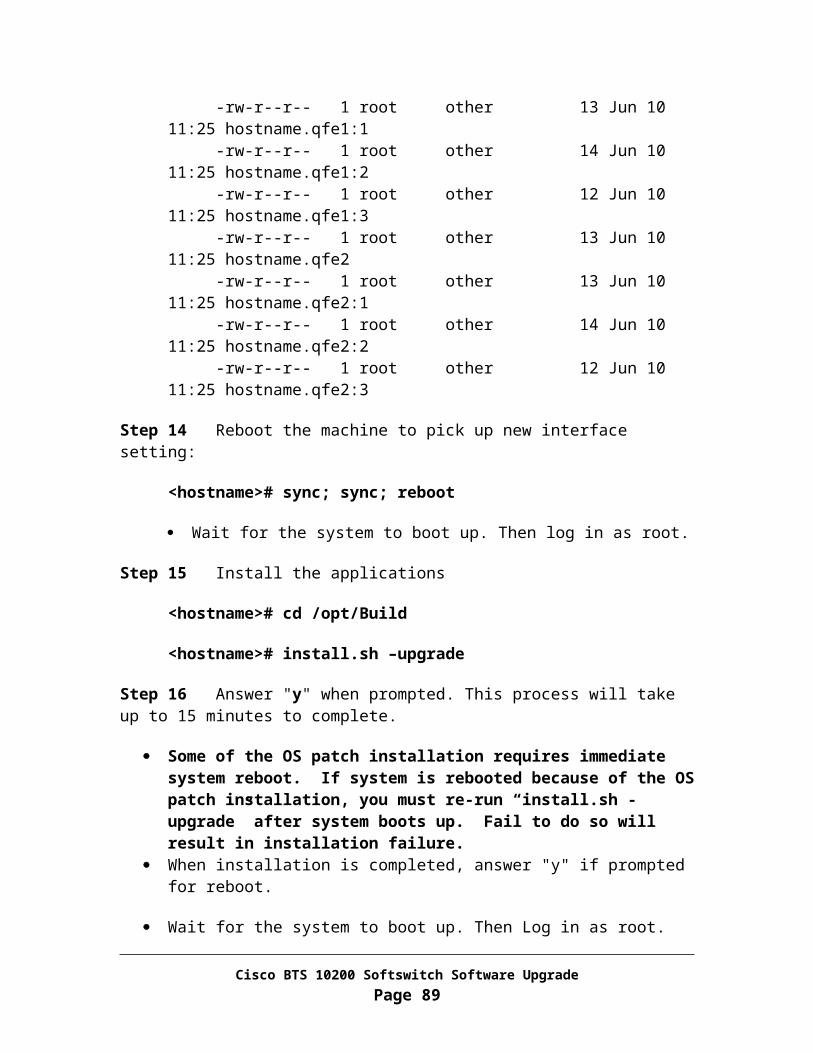
Step 5 If the “Deferror is empty?” is “NO”, please try to correct the error using steps in “Correct replication error” below. If you are unable to clear the error or if any of the individual steps fails, please contact Cisco Support.
Step 6 <hostname> $ exit
Correct replication error
Note You must run the following steps on standby EMS side B first, then on active EMS side A.
From EMS Side B
Step 1 Log in as root
Step 2 <hostname># su – oracle
Step 3 <hostname>$ dbadm –C db
The above command will generate a list of out of sync tables. Example Output:
o <hostname> $ dbadm –C db Checking table => OAMP.SCHEDULED COMMAND…..Different
In the above output, OWNER = OAMP and TABEL NAME = SCHEDULED COMMAND
Step 4 For each table that is out of sync, please run the following step:
<hostname>$ dbadm -A copy -o <OWNER> -t <TABEL NAME>
Enter “y” to continue Please contact Cisco Support if the above command fails.
Step 5 <hostname>$ dbadm –A truncate_deferror
Enter “y” to continue
Step 6 <hostname> $ exit
Cisco BTS 10200 Softswitch Software UpgradePage 89

From EMS Side A
Step 1 Login in as root.
Step 2 <hostname> # su – oracle
Step 3 <hostname>$ dbadm –A truncate_deferror
Enter “y” to continue
Step 4 Re-verify that “Deferror is empty?” is “YES” and none of tables is out of sync.
<hostname>$dbadm –C db
OPTICAL1::Deftrandest is empty? YESOPTICAL1::dba_repcatlog is empty? YESOPTICAL1::Deferror is empty? YES Make sure it is “YES”OPTICAL1::Deftran is empty? YESOPTICAL1::Has no broken job? YESOPTICAL1::JQ Lock is empty? YES
OPTICAL2::Deftrandest is empty? YESOPTICAL2::dba_repcatlog is empty? YESOPTICAL2::Deferror is empty? YES Make sure it is “YES”OPTICAL2::Deftran is empty? YESOPTICAL2::Has no broken job? YESOPTICAL2::JQ Lock is empty? YES
Step 5 <hostname> # exit
Cisco BTS 10200 Softswitch Software UpgradePage 90

Appendix FBackout Procedure for Side B Systems
Warning After entire system is upgraded to release 4.5.1, if the system is provisioned with new CLI data fallback is not recommended. If fallback is absolutely required, please contact Cisco support.
Introduction
This procedure allows you to back out of the upgrade procedure if any verification checks (in "Verify Call/System Status" section) failed. This procedure is intended for the scenario in which the side B systems have been upgraded to the new load, while the side A systems are still at the previous load. The procedure will back out the side B systems to the previous load.
This backout procedure will:
Restore the side A systems to active mode without making any changes to it Revert to the previous application load on the side B systems Restart the side B systems in standby mode Verify that the system is functioning properly with the previous load
Note In addition to performing this backout procedure, you should contact Cisco Support when you are ready to retry the upgrade procedure.
The flow for this procedure is shown in Figure F-1.
Cisco BTS 10200 Softswitch Software UpgradePage 91

Figure F-1 Flow of Backout Procedure— Side B Only
Task 1: Force side A CA/FS to active
This procedure will force the side A systems to forced active state, and the side B systems to forced standby state.
Note In the commands below, "xxx", "yyy" or "zzz" is the instance for the process on your system.
Cisco BTS 10200 Softswitch Software UpgradePage 92

From EMS side B
Step 1 Log in as “btsuser” user.
Step 2 CLI> control call-agent id=CAxxx; target-state=active-standby;
Step 3 CLI> control feature-server id=FSPTCyyy; target-state=active-standby;
Step 4 CLI> control feature-server id=FSAINzzz; target-state=active-standby;
Step 5 CLI> exit
Task 2: Force side A EMS to active
From EMS side B
Step 1 Log in as root
Step 2 <hostname># platform stop all
Task 3: Sync TSAP-ADDR
From EMS side A
Step 1 Log in as “ciscouser”
CLI> sync call_agent master=EMS; target=CAxxx;
CLI> sync feature_server master=EMS; target=FSAINxxx;
CLI> sync feature_server master=EMS; target=FSPTCxxx;
Task 4: SFTP billing records to a mediation device
Cisco BTS 10200 Softswitch Software UpgradePage 93

From EMS side B
Step 1 Log in as root
Step 2 <hostname># cd /opt/bms/ftp/billing
Step 3 <hostname># ls
Step 4 If there are files listed, then SFTP the files to a mediation device on the network and remove the files from the /opt/bms/ftp/billing directory
Task 5: Sync DB usage
From EMS side A
In this task, you will sync db-usage between two releases.
Step 1 Log in as root
Step 2 <hostname># su – oracle
Step 3 <hostname>$ java dba.adm.DBUsage –sync
Verify Number of tables “unable-to-sync” is 0.
Step 4 <hostname>$ exit
Task 6: Stop applications and shutdown side B systems
From EMS side B
Step 1 Log in as root.
Step 2 <hostname># sync; sync
Step 3 <hostname># shutdown –i5 –g0 –y
Cisco BTS 10200 Softswitch Software UpgradePage 94

From CA/FS side B
Step 1 Log in as root.
Step 2 <hostname># platform stop all
Step 3 <hostname># sync; sync
Step 4 <hostname># shutdown –i5 –g0 –y
Task 7: Restore side B systems to the old release
From CA/FS side B
Step 1 Power off the machine
Step 2 Remove disk0 from slot 0 off the machine. Also remove disk1 from slot 1 off the machine.
SunFire V440 disk slot lay out:
Disk 3 DVD-ROM
Disk 2
Disk 1
Disk 0 Sunfire 1280 disk slot lay out:
DVD-ROM
Disk 1
Disk 0
Cisco BTS 10200 Softswitch Software UpgradePage 95

Step 3 Place disk labeled “Release 4.4.0 CA/FS side B disk0” in slot 0. Also place disk labeled “Release 4.4.0 CA/FS side B disk1” in slot 1.
Step 4 Power on the machine
For a Sunfire 1280 machine, please execute the following command from console:
<lom>poweron
For other type of hardware, please use the power button to turn on the power.
Step 5 Log in as root.
Step 6 <hostname># platform start
Step 7 <hostname># mv /etc/rc3.d/_S99platform /etc/rc3.d/S99platform
From EMS side B
Step 1 Power off the machine
Step 2 Remove disk0 from slot 0 off the machine. Also remove disk1 from slot 1 off the machine.
SunFire V440 disk slot lay out:
Disk 3 DVD-ROM
Disk 2
Disk 1
Disk 0 Sunfire 1280 disk slot lay out:
DVD-ROM
Disk 1
Disk 0
Cisco BTS 10200 Softswitch Software UpgradePage 96

Step 3 Place disk labeled “Release 4.4.0 EMS side B disk0” in slot 0. Also place disk labeled “Release 4.4.0 EMS side B disk1” in slot 1.
Step 4 Power on the machine
For a Sunfire 1280 machine, please execute the following command from console:
<lom>poweron
For other type of hardware, please use the power button to turn on the power.
Step 5 Log in as root.
Step 6 <hostname># platform start
Step 7 <hostname># mv /etc/rc3.d/_S99platform /etc/rc3.d/S99platform
Task 8: Restore EMS mate communication
In this task, you will restore the OMS Hub communication from EMS side A to side B.
From EMS side A
Step 1 Log in as root
Step 2 <hostname># /opt/ems/utils/updMgr.sh –restore_hub
Step 3 <hostname># nodestat
Verify OMS Hub mate port status is established. Verify HUB communication from EMS side A to CA/FS side B is established.
Task 9: Switchover activity to EMS side B
From Active EMS side A
Step 1 Log in as “btsuser” user.
Cisco BTS 10200 Softswitch Software UpgradePage 97

Step 2 CLI> control bdms id=BDMS01; target-state=forced-standby-active;
Step 3 CLI> control element-manager id=EM01; target-state=forced-standby-active;
Step 4 CLI Log in session will be terminated when switchover is completed.
Task 10: Enable Oracle DB replication on EMS side A
From EMS side A
Step 1 Log in as Oracle user:
<hostname># su - oracle
<hostname>$ cd /opt/oracle/admin/utl
Step2 Restore Oracle DB replication:
<hostname>$ rep_toggle –s optical1 –t set_duplex
Answer “y” when promptAnswer “y” again when prompt
Step 3 <hostname>$ exit
Step 4 Restart applications to connect to Oracle DB in duplex mode:
<hostname># platform stop all
<hostname># platform start
Task 11: Synchronize handset provisioning data
From EMS side B
Note In the commands below, "xxx", "yyy" or "zzz" is the instance for the process on your system.
Cisco BTS 10200 Softswitch Software UpgradePage 98

Step 1 Log in as ciscouser (password: ciscosupport)
Step 2 CLI> sync termination master=CAxxx; target=EMS;
Verify the transaction is executed successfully.
Step 3 CLI> sync sc1d master=FSPTCyyy; target=EMS;
Verify the transaction is executed successfully
Step 4 CLI> sync sc2d master=FSPTCyyy; target=EMS;
Verify the transaction is executed successfully
Step 5 CLI> sync sle master=FSPTCyyy; target=EMS;
Verify the transaction is executed successfully
Step 6 CLI> sync subscriber-feature-data master=FSPTCyyy; target=EMS;
Verify the transaction is executed successfully
Step 7 CLI> exit
Task 12: Switchover activity from EMS side B to EMS side A
From EMS side B
Step 1 Log in as “btsuser” user.
Step 2 CLI> control bdms id=BDMS01; target-state=forced-active-standby;
Step 3 CLI> control element-manager id=EM01; target-state=forced-active-standby;
Step 4 CLI Log in session will be terminated when switchover is completed.
Cisco BTS 10200 Softswitch Software UpgradePage 99

Task 13: Restore system to normal mode
From EMS side A
Step 1 Log in as “btsuser” user.
Step 2 CLI> control feature-server id=FSPTCyyy; target-state=normal;
Step 3 CLI> control feature-server id=FSAINzzz; target-state=normal;
Step 4 CLI> control call_agent id=CAxxx; target-state=normal;
Step 5 CLI> control bdms id=BDMS01; target-state=normal;
Step 6 CLI> control element-manager id=EM01; target-state=normal;
Step 7 CLI> exit
Task 14: Verify system status
Verify that the system is operating properly before you leave the site.
Step 1 Verify that the side A systems are in the active state. Use Appendix A for this procedure.
Step 2 Verify that call processing is working without error. Use Appendix B for this procedure.
Step 3 Verify that provisioning is operational from CLI command line, and verify database. Use Appendix C for this procedure.
Step 4 Verify that there are no outstanding major or critical alarms. Use Appendix D for this procedure.
Step 5 Use Appendix E to verify that Oracle database and replication functions are working properly.
Step 6 From each machine, please run “/opt/utils/Resync_status” to check for disk mirroring status.
Cisco BTS 10200 Softswitch Software UpgradePage 100

Step 7 If you answered NO to any of the above questions (Step 1 through Step 5), Contact Cisco Support for assistance.
You have completed the side B of Cisco BTS 10200 system fallback process successfully.
Cisco BTS 10200 Softswitch Software UpgradePage 101

Appendix G
Software Upgrade Disaster Recovery Procedure
Disaster Recovery Requirements
This procedure is recommended only when full system upgrade to release 4.5.1 MR1 has been completed and the system is experiencing unrecoverable problems for which the only solution is to take a full system service outage and restore to the previously working release as quickly as possible.
Assumptions
The following assumptions are made. The installer has a basic understanding of UNIX and Oracle commands. The installer has the appropriate user name(s) and password(s) to log on to each
EMS/CA/FS platform as root user, and as Command Line Interface (CLI) user on the EMS.
Total live traffic outage for a period of approximately 30 minutes is acceptable All analysis of the outage is leading to the BTS as the main contributor in the
current situation
Note: Contact Cisco Support before you start if you have any questions.
Requirements
Cisco BTS 10200 Softswitch Software UpgradePage 102

Locate release 4.4.X disks with following label: Side A EMS -- “Release 4.4.X EMS side A” Side B EMS -- “Release 4.4.X EMS side B” Side A CA/FS -- “Release 4.4.X CA/FS side A” Side B CA/FS -- “Release 4.4.X CA/FS side B”
Important notes about this procedure
Throughout this procedure, each command is shown with the appropriate system prompt, followed by the command to be entered in bold. The prompt is generally one of the following:
Host system prompt (<hostname>#) Oracle prompt (<hostname>$) SQL prompt (SQL>) CLI prompt (CLI>) SFTP prompt (sftp>) Ok prompt (ok>)
1. Throughout the steps in this procedure, enter commands as shown, as they are case sensitive (except for CLI commands).
2. It is recommended that you read through the entire procedure before performing any steps.
3. The system will incur about 30 minutes of total live traffic outage before side B systems can be fully functional. Please plan accordingly to minimize any negative service impact.
4. There will be no new provisioning allowed during entire disaster recovery process.
5. Newly provisioned data including handset and CLI data, after the point that side B system disks were swapped out are lost.
Cisco BTS 10200 Softswitch Software UpgradePage 103

System Disaster Recovery ProcedureWarning Executing this backout procedure will result in loss of all provisioning data which includes north bound handset data from the point where the side B system disks were swapped out. Loss of billing CDR is also expected.
Introduction
This backout procedure allows you to restore the BTS system back to release 4.4.X. This procedure is intended for the disaster scenario in which the entire system has been upgraded to the release 4.5.1 MR1 load and calls cannot be made or maintained.
This backout procedure will:
Power off each BTS machine Restore the side-B systems with release 4.4.X disks Bring up applications to active mode without making any changes to it Verify that the system is functioning properly with the previous load Restore the side-A systems with release 4.4.X disks Restart the side-A systems in standby mode Control the system to a normal operational state -- side A active, side B standby
Note: In addition to performing this backout procedure, you should contact Cisco Support when you are ready to retry the upgrade procedure.
Task 1: Shutdown each machine
From CA/FS side B
Step 1 Login to the CA/FS Side B machine through console server and shutdown the machine.
<hostname># eeprom diag-level=init (For SUN 1280’s only)
<hostname># sync;sync;shutdown –i5 –g0 –y
Notice the normal console prompt is now changed to lom>
Cisco BTS 10200 Softswitch Software UpgradePage 104

Step 2 Remove disk0 from slot 0 off the machine with label “Release 4.5.1 MR1 CA/FS side B disk0”. Also remove disk1 from slot 1 off the machine with label “Release 4.5.1 MR1 CA/FS side B disk1”.
Sunfire 1280 disk slot lay out:
DVD-ROM
Disk 1
Disk 0
Step 3 Place disk labeled with “Release 4.4.X CA/FS side B disk0” in slot 0. Also place disk labeled with “Release 4.4.X CA/FS side B disk1” in slot 1.
From EMS side B
Step 1 Login to the EMS Side B machine through console server and shutdown the machine.
<hostname># eeprom diag-level=init (For SUN 1280’s only)
<hostname># sync;sync;shutdown –i5 –g0 –y
Notice the normal console prompt is now changed to lom>
Step 2 Remove disk0 from slot 0 off the machine with label “Release 4.5.1 MR1 EMS side B disk0”. Also remove disk1 from slot 1 off the machine with label “Release 4.5.1 MR1 EMS side B disk1”.
Sunfire 1280 disk slot lay out:
DVD-ROM
Disk 1
Disk 0
Step 3 Place disk labeled with “Release 4.4.X EMS side B disk0” in slot 0. Also place disk labeled with “Release 4.4.X EMS side B disk1” in slot 1.
Cisco BTS 10200 Softswitch Software UpgradePage 105

From CA/FS side A
Step 1 Login to the CA/FS Side A machine through console server and shutdown all applications
<hostname># platform stop all
<hostname># cd /opt/ems/bin
<hostname># daemon_mgr.sh stop
<hostname># daemon_mgr.sh remove
From EMS side A
Step 1 Login to the EMS Side A machine through console server and shutdown all applications
<hostname># platform stop all
<hostname># cd /opt/ems/bin
<hostname># daemon_mgr.sh stop
<hostname># daemon_mgr.sh remove
Task 2: Restore CA/FS side B to the old release
From CA/FS side B
Step 1 Power on the machine
<lom>poweron
Cisco BTS 10200 Softswitch Software UpgradePage 106
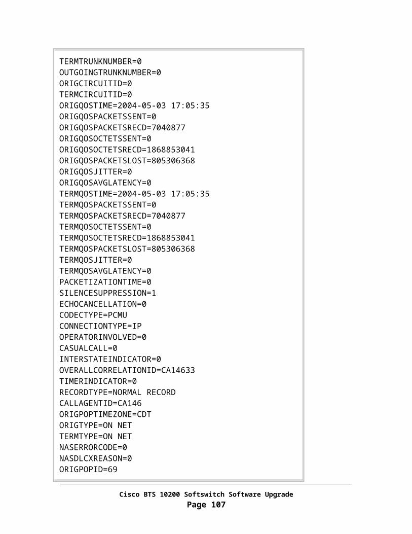
Step 2 Monitor the system boot progress thru console, log back in when system completes boot process
Note: It is recommended to perform Task 3 and Task 4 in parallel.
Task 3: Bring up applications on CA/FS side B
From CA/FS side B
Step 1 Login as root.
Step 2 <hostname># platform start
Step 3 <hostname># mv /etc/rc3.d/_S99platform /etc/rc3.d/S99platform
Task 4: Restore EMS side B to the old release
From EMS side B
Step 1 Power on the machine
<lom>poweron
Step 2 Monitor the system boot progress thru console, log back in when system completes boot process
Step 3 Login as root.
Step 4 <hostname># platform start
Step 5 <hostname># mv /etc/rc3.d/_S99platform /etc/rc3.d/S99platform
Cisco BTS 10200 Softswitch Software UpgradePage 107

Task 5: Verify system health
Verify that the system is functioning properly with the previous load
Step 1 Verify that call processing is working by making on-net and off net calls
Step 2 Verify that Billing CDRs are being generated with correct billing details for the calls just made
Log in to EMS side B as CLI user CLI> report billing-record tail=<Choose # CDRs to be displayed>;
Step 3 Verify CLI data provision is functioning properly from EMS side B
CLI> add carrier id=8080; CLI> show carrier id=8080;
CLI> delete carrier id=8080;
CLI> show carrier id=8080;
CLI> show transaction-queue;
o You should expect to see following:
Reply : Success: Database is void of entries.
CLI> exit;
Step 4 Verify Oracle DB replication on EMS side B is enabled:
<hostname># su - oracle<hostname>$ cd /opt/oracle/admin/utl<hostname>$ rep_toggle -s optical2 -t show_mode
o You should expect to see following:
The optical2 database is set to DUPLEX now.
<hostname># exit
Cisco BTS 10200 Softswitch Software UpgradePage 108

Step 5 If you answered NO to any of the above questions (Step 1 through Step 4), Contact Cisco Support for assistance.
Note: It is recommended to perform Task 6 and Task 7 in parallel.
Task 6: Restore CA/FS side A to the old release
From CA/FS side A
Step 1 Login to the CA/FS Side A machine through console server and shutdown the machine.
<hostname># eeprom diag-level=init (For SUN 1280’s only)
<hostname># sync;sync;shutdown –i5 –g0 –y
Notice the normal console prompt is now changed to lom>
Step 2 Remove disk0 from slot 0 off the machine with label “Release 4.5.1 MR1 CA/FS side A disk0”. Also remove disk1 from slot 1 off the machine with label “Release 4.5.1 MR1 CA/FS side A disk1”.
Sunfire 1280 disk slot lay out:
DVD-ROM
Disk 1
Disk 0
Step 3 Place disk labeled with “Release 4.4.X CA/FS side A disk0” in slot 0. Also place disk labeled with “Release 4.4.X CA/FS side A disk1” in slot 1.
Step 4 Power on the machine
<lom>poweron
Cisco BTS 10200 Softswitch Software UpgradePage 109
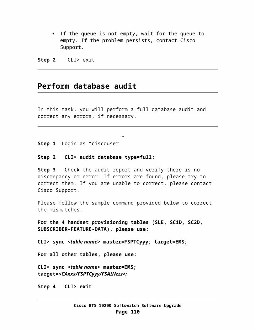
Step 5 Monitor the system boot progress thru console, log back in when system completes boot process
Step 6 <hostname># /opt/ems/utils/install.sh -clearshm
Answer “y” when prompt
Step 7 Login as root.
Step 8 <hostname># platform start
Step 9 <hostname># mv /etc/rc3.d/_S99platform /etc/rc3.d/S99platform
Task 7: Restore EMS side A to the old release
From EMS side A
Step 1 Login to the EMS Side A machine through console server and shutdown the machine.
<hostname># eeprom diag-level=init (For SUN 1280’s only)
<hostname># sync;sync;shutdown –i5 –g0 –y
Notice the normal console prompt is now changed to lom>
Step 2 Remove disk0 from slot 0 off the machine with label “Release 4.5.1 MR1 EMS side A disk0”. Also remove disk1 from slot 1 off the machine with label “Release 4.5.1 MR1 EMS side A disk1”.
Sunfire 1280 disk slot lay out:
DVD-ROM
Disk 1
Disk 0
Step 3 Place disk labeled with “Release 4.4.X EMS side A disk0” in slot 0. Also place disk labeled with “Release 4.4.X EMS side A disk1” in slot 1.
Cisco BTS 10200 Softswitch Software UpgradePage 110

Step 4 Power on the machine:
<lom>poweron
Step 5 Monitor the system boot progress thru console, log back in when system completes boot process
Step 6 <hostname># /opt/ems/utils/updMgr.sh -restore_hub
Step 7 Login as root.
Step 8 <hostname># platform start -i oracle
Step 9 Log in as Oracle user:
<hostname># su – oracle
Step 10 Copy data from EMS side B:
<hostname>$ cd /opt/oracle/admin/upd<hostname>$ java dba.upd.UPDMgr -loadconfig<hostname>$ java dba.upd.UPDMgr -skip reset copy<hostname>$ java dba.upd.UPDMgr -copy all
<hostname>$ grep "FAIL=" UPDMgr.log
Verify the FAIL count 0 is reported
<hostname>$ grep constraint UPDMgr.log | grep –i warning
Verify there is no constraint warning reported
Note: if FAIL count is not 0 and/or there is constraint warning, please contact Cisco support.
Step 11 Set EMS side A replication to duplex:
<hostname>$ cd /opt/oracle/admin/utl <hostname>$ rep_toggle -s optical1 -t set_duplex
Answer “y” when prompt Answer “y” again when prompt
Cisco BTS 10200 Softswitch Software UpgradePage 111

Step 12 <hostname>$ java dba.adm.DBUsage –sync
Verify Number of tables “unable-to-sync” is 0.
Step 13 <hostname>$ exit
Step 14 Make sure all oracle DB connections are terminated:
<hostname># platform stop -i oracle
Step 15 Bring up all BTS applications:
<hostname># platform start
Step 16 <hostname># mv /etc/rc3.d/_S99platform /etc/rc3.d/S99platform
Task 8:Enable Bulk Provisioning from EMS side A & B
Step 1 Login as root on EMS
Step 2 Enable bulk provisioning.
<hostname># cd /opt/ems/bin
<hostname># echo "update PlatformPrograms set enable='Y' where id='DLP';" | mysql_cli.sh
<hostname># pkill smg
Task 9: Verify system status
Verify that the system is operating properly before you leave the site.
Step 1 Perform full database audit between EMS and CA/FS:
Log in to EMS side B as CLI user CLI> audit database;
Cisco BTS 10200 Softswitch Software UpgradePage 112

o Check audit report. If there are any mismatches found, please contact Cisco support immediately.
CLI> exit;
Step 2 Performance Oracle DB audit between EMSs:
<hostname># su - oracle<hostname>$ dbadm -C db
o You should expect to see following:
optical2:secems36:/opt/orahome$ dbadm -C db
OPTICAL2::Deftrandest is empty? YESOPTICAL2::dba_repcatlog is empty? YESOPTICAL2::Deferror is empty? YESOPTICAL2::Deftran is empty? YESOPTICAL2::Has no broken job? YESOPTICAL2::JQ Lock is empty? YES
OPTICAL1::Deftrandest is empty? YESOPTICAL1::dba_repcatlog is empty? YESOPTICAL1::Deferror is empty? YESOPTICAL1::Deftran is empty? YESOPTICAL1::Has no broken job? YESOPTICAL1::JQ Lock is empty? YES
You are connecting to OPTICAL2, remote DB is OPTICAL1
…
Number of tables to be checked: 195Number of tables checked OK: 195Number of tables out-of-sync: 0
o If “Number of tables out-of-sync” is not 0, please contact Cisco support immediately.
<hostname>$ exit
Step 3 Check for critical and major alarms
Log in to EMS side B as CLI user
Cisco BTS 10200 Softswitch Software UpgradePage 113

CLI> show alarm severity=MAJOR;
CLI> show alarm severity=CRITICAL;
CLI> exit
o Check report. Please determine each major and critical condition, contact Cisco support if necessary.
Step 4 If you encounter issues in any of the above steps (Step 1 through Step 3), Contact Cisco Support for assistance.
You have completed the disaster recovery process successfully.
Cisco BTS 10200 Softswitch Software UpgradePage 114

Appendix HPreparing Disks for Upgrade
This software upgrade will need 8 disks: 2 for each machine. Each set of 2 disks must have the same model number in order for disk mirroring to work.
The NIDS information required for disk preparation must be different from that used on the system to be upgraded.
The disk preparation/staging should be done on a separate platform (from the system to be upgraded), but the hardware should be identical.
Task 1: Locate CD-ROM Discs
Please locate following 3 CD-ROM Discs:
1. Locate CD-ROM Disc labeled as “BTS 10200 Application”2. Locate CD-ROM Disc labeled as “BTS 10200 Database”3. Locate CD-ROM Disc labeled as “BTS 10200 Oracle Engine”
Task 2: Locate and label the Disks
Label disks for EMS Side A
Locate two new disk drives identical to the machine to be upgraded and label the first disk drive as “Release 4.5.1 MR1 EMS side A disk0” and the second disk drive as “Release 4.5.1 MR1 EMS side A disk1”. Please follow the steps below to prepare the two disk drives. The second disk drive will be used as the backup in case the first disk drive goes bad.
Cisco BTS 10200 Softswitch Software UpgradePage 115

Label Disks for EMS Side B
Locate two new disk drives identical to the machine to be upgraded and label the first disk drive as “Release 4.5.1 MR1 EMS side B disk0” and the second disk drive as “Release 4.5.1 MR1 EMS side B disk1”. Please follow the steps below to prepare the two disk drives. The second disk drive will be used as the backup in case the first disk drive goes bad.
Label Disks for CA/FS Side A
Locate two new disk drives identical to the machine to be upgraded and label the first disk drive as “Release 4.5.1 MR1 CA/FS side A disk0” and the second disk drive as “Release 4.5.1 MR1 CA/FS side A disk1”. Please follow the steps below to prepare the two disk drives. The second disk drive will be used as the backup in case the first disk drive goes bad.
Label Disks for CA/FS Side B
Locate two new disk drives identical to the machine to be upgraded and label the first disk drive as “Release 4.5.1 MR1 CA/FS side B disk0” and the second disk drive as “Release 4.5.1 MR1 CA/FS side B disk1”. Please follow the steps below to prepare the two disk drives. The second disk drive will be used as the backup in case the first disk drive goes bad.
Task 3: Disk slot lay out
SunFire V440 disk slot lay out:
Disk 3 DVD-ROM
Disk 2
Disk 1
Disk 0 Sunfire 1280 disk slot lay out:
Cisco BTS 10200 Softswitch Software UpgradePage 116
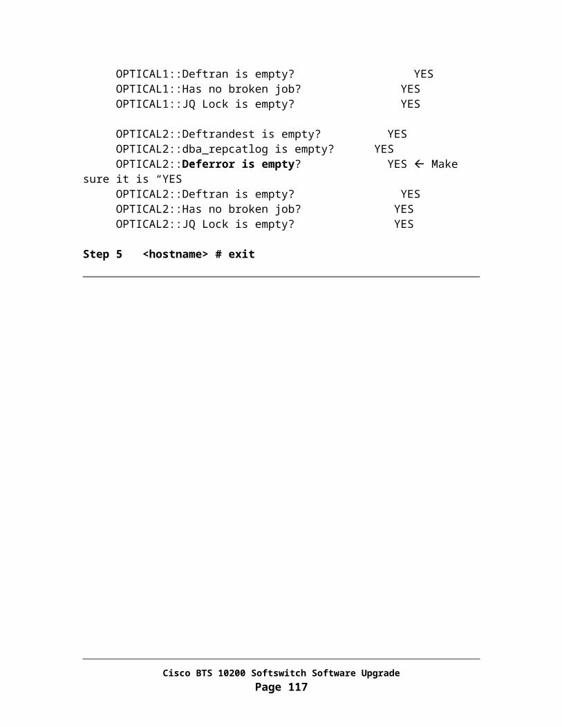
DVD-ROM
Disk 1
Disk 0
Task 4: Construct opticall.cfg
Step 1 Get a copy of Cisco BTS 10200 Software Release 4.5.1 Network Information Data Sheets (NIDS). Please follow the link below for NIDS and opticall.cfg information: http://lbj/push_targets1/ucdit/cc/td/doc/product/voice/bts10200/bts4_5/install/nids_45.xls
Step 2 Fill in NIDS information for the BTS system used for disk preparation. The NIDS information must be different from that used on the system to be upgraded.
Step 3 Get a copy of Cisco BTS 10200 Software Release 4.5.1 opticall.cfg
Step 4 Fill in parameters in opticall.cfg from NIDS and placed it on a server which will be accessible from the BTS system used for disk preparation.
Task 5: Disk preparation
Repeat the steps in Task 5 to prepare the second disk.
Note: Please perform disk preparation for each machine in parallel.
For both EMS side A and B
Step 1 Locate a system with the identical hardware as the machine to be upgraded
Step 2 Place disk0 to slot 0 and disk 1 to slot 1
Cisco BTS 10200 Softswitch Software UpgradePage 117

Step 3 Jumpstart the machine with Solaris 10 OS by following the jumpstart procedure: http://lbj/push_targets1/ucdit/cc/td/doc/product/voice/bts10200/bts4_5/install/sol10cdj.doc
Step 4 Configured the machine with 4/2 network configuration
Step 5 Stage Cisco BTS 10200 Software Release 4.5.1 to the /opt/Build directory.
From EMS Side B:
Log in as root Put Disc labeled as BTS 10200 Application Disc in the CD-ROM drive Remove old files and mount CD-ROM drive
<hostname># cd /<hostname># \rm -rf /opt/Build<hostname># mkdir -p /cdrom<hostname># mount -o ro -F hsfs /dev/dsk/c0t0d0s0 /cdrom
Copy file from the CD-ROM to the /opt directory.
<hostname># cp –f /cdrom/K9-opticall.tar.gz /opt
Verify that the check sum values match with the values located in the “checksum.txt” file located on Application Disc
<hostname># cat /cdrom/checksum.txt<hostname># cksum /opt/K9-opticall.tar.gz<hostname># umount /cdrom
Manually eject the CD-ROM and take out Disc from drive Put Disc labeled as BTS 10200 Database Disc in the CD-ROM drive Mount and copy file
<hostname># mount -o ro -F hsfs /dev/dsk/c0t0d0s0 /cdrom<hostname># cp –f /cdrom/K9-btsdb.tar.gz /opt<hostname># cp –f /cdrom/K9-extora.tar.gz /opt
Verify that the check sum values match with the values located in the “checksum.txt” file located on Oracle CD-ROM.
<hostname># cat /cdrom/checksum.txt<hostname># cksum /opt/K9-btsdb.tar.gz<hostname># cksum /opt/K9-extora.tar.gz<hostname># umount /cdrom
Cisco BTS 10200 Softswitch Software UpgradePage 118
Manually eject the CD-ROM and take out Disc from drive If you have Customer Built Oracle DB engine, please use the Disc provided
by the customer. Otherwise, put Disc labeled as BTS 10200 Oracle Engine Disc in the CD-ROM drive
Mount and copy file
<hostname># mount -o ro -F hsfs /dev/dsk/c0t0d0s0 /cdrom<hostname># cp –f /cdrom/K9-oraengine.tar.gz /opt
Verify that the check sum values match with the values located in the “checksum.txt” file located on Oracle CD-ROM.
<hostname># cat /cdrom/checksum.txt<hostname># cksum /opt/K9-oraengine.tar.gz<hostname># umount /cdrom
Manually eject the CD-ROM and take out Disc from drive Ftp files to EMS side A
<hostname># cd /opt<hostname># sftp <EMS Side A hostname>sftp> cd /optsftp> put K9-opticall.tar.gzsftp> put K9-btsdb.tar.gz sftp> put K9-extora.tar.gzsftp> put K9-oraengine.tar.gzsftp> exit
Extract tar files.
<hostname># gzip -cd K9-opticall.tar.gz | tar -xvf -<hostname># gzip -cd K9-btsdb.tar.gz | tar -xvf -<hostname># gzip -cd K9-extora.tar.gz | tar -xvf -<hostname># gzip -cd K9-oraengine.tar.gz | tar -xvf -
Note: Each file will take up 5-10 minutes to extract.
From EMS Side A:
Log in as root Remove old files and extract new files
<hostname># cd /opt<hostname># \rm -rf Build<hostname># gzip -cd K9-opticall.tar.gz | tar -xvf -
Cisco BTS 10200 Softswitch Software UpgradePage 119

<hostname># gzip -cd K9-btsdb.tar.gz | tar -xvf -<hostname># gzip -cd K9-extora.tar.gz | tar -xvf -<hostname># gzip -cd K9-oraengine.tar.gz | tar -xvf -
Note: Each file will take up 5-10 minutes to extract.
Step 6 ftp opticall.cfg from the server (where the file was placed in Task 4 above) and place it under /etc directory.
<hostname># /opt/Build/checkCFG
Verify the information in /etc/opticall.cfg is free of errors.
Note: The EMS side A and side B installation must be started in parallel.
From both EMS:
Step 7 Install Cisco BTS 10200 Software Release 4.5.1 application software.
<hostname># /opt/Build/install.sh
o Answer “y” when prompt. This installation process could take up to 1hour and 30 minutes.
o Answer "y” when prompt for “reboot”
o Wait for the system to boot up. Then Log in as root
Step 8 <hostname># mv /etc/rc3.d/S99platform /etc/rc3.d/_S99platform
Step 9 Shutdown the applications
<hostname># platform stop all
Step 10 Mirror the disks.
<hostname># /opt/setup/setup_mirror_ems
<hostname># sync;sync;reboot -- -r
o Wait for the system to boot then log in to EMS Side B as root.
Cisco BTS 10200 Softswitch Software UpgradePage 120

<hostname># /opt/setup/sync_mirror
Note: It takes 2 to 2.5 hours to complete the disk mirroring process on each machine. Please run “/opt/utils/Resync_status” to check for the disk mirroring status. The display will show the resyncing in progress and reports resync completion.
Step 11 Remove all network interface configuration information from the machine:
<hostname># \rm /etc/hostname.*
Step 12 Shutdown and power off the machine then remove the disks to be used for upgrade.
<hostname># sync;sync;shutdown –i5 –g0 -y
For both CA/FS side A and B
Step 1 Locate a system with the identical hardware as the machine to be upgraded
Step 2 Place disk0 to slot 0 and disk 1 to slot 1
Step 3 Jumpstart the machine with Solaris 10 OS by following the jumpstart procedure: http://lbj/push_targets1/ucdit/cc/td/doc/product/voice/bts10200/bts4_5/install/sol10cdj.doc
Step 4 Configured the machine with 4/2 network configuration
Step 5 Stage Cisco BTS 10200 Software Release 4.5.1 to the /opt/Build directory.
From CA/FS Side B:
Log in as root Put Disc labeled as BTS 10200 Application Disc in the CD-ROM drive Remove old files and mount CD-ROM drive
<hostname># cd /<hostname># \rm -rf /opt/Build<hostname># mkdir -p /cdrom<hostname># mount -o ro -F hsfs /dev/dsk/c0t0d0s0 /cdrom
Copy file from the CD-ROM to the /opt directory.
Cisco BTS 10200 Softswitch Software UpgradePage 121

<hostname># cp –f /cdrom/K9-opticall.tar.gz /opt
Verify that the check sum values match with the values located in the “checksum.txt” file located on Application Disc
<hostname># cat /cdrom/checksum.txt<hostname># cksum /opt/K9-opticall.tar.gz<hostname># umount /cdrom
Manually eject the CD-ROM and take out Disc from drive Ftp files to CA/FS side A
<hostname># cd /opt<hostname># sftp <CA/FS Side A hostname>sftp> cd /optsftp> put K9-opticall.tar.gzsftp> exit
Extract tar files.
<hostname># gzip -cd K9-opticall.tar.gz | tar -xvf –
Note: The file will take up 5-10 minutes to extract.
From CA/FS Side A:
Log in as root Remove old files and extract new files
<hostname># cd /opt<hostname># \rm -rf Build<hostname># gzip -cd K9-opticall.tar.gz | tar -xvf -
Note: The file will take up 5-10 minutes to extract.
From both CA/FS:
Step 6 ftp opticall.cfg from the server (where the file was placed in Task 4 above) and place it under /etc directory.
Step 7 Install BTSbase, BTSinst, BTSossh and BTShard packages:
Cisco BTS 10200 Softswitch Software UpgradePage 122

<hostname># cd /opt/Build <hostname># pkgadd –d . BTSbase Answer “y” when prompt <hostname># pkgadd –d . BTSinst Answer “y” when prompt <hostname># pkgadd –d . BTSossh Answer “y” when prompt <hostname># pkgadd –d . BTShard Answer “y” when prompt <hostname># cd /etc/rc3.d <hostname># mv S99platform _S99platform <hostname># sync;sync;reboot Wait for system to boot up and login as root.
Step 8 Update version information:
<hostname># echo “900-04.04.00.V00” > /opt/ems/utils/Version
Step 9 Mirror the disks.
<hostname># /opt/setup/setup_mirror_ca
<hostname># sync;sync;reboot -- -r
o Wait for the system to boot then log in to EMS Side B as root.
<hostname># /opt/setup/sync_mirror
Note: It takes 2 to 2.5 hours to complete the disk mirroring process on each machine. Please run “/opt/utils/Resync_status” to check for the disk mirroring status. The display will show the resyncing in progress and reports resync completion.
Step 10 Remove all network interface configuration information from the machine:
<hostname># \rm /etc/hostname.*
Step 11 Shutdown and power off the machine then remove the disks to be used for upgrade.
<hostname># sync;sync;shutdown –i5 –g0 -y
Cisco BTS 10200 Softswitch Software UpgradePage 123
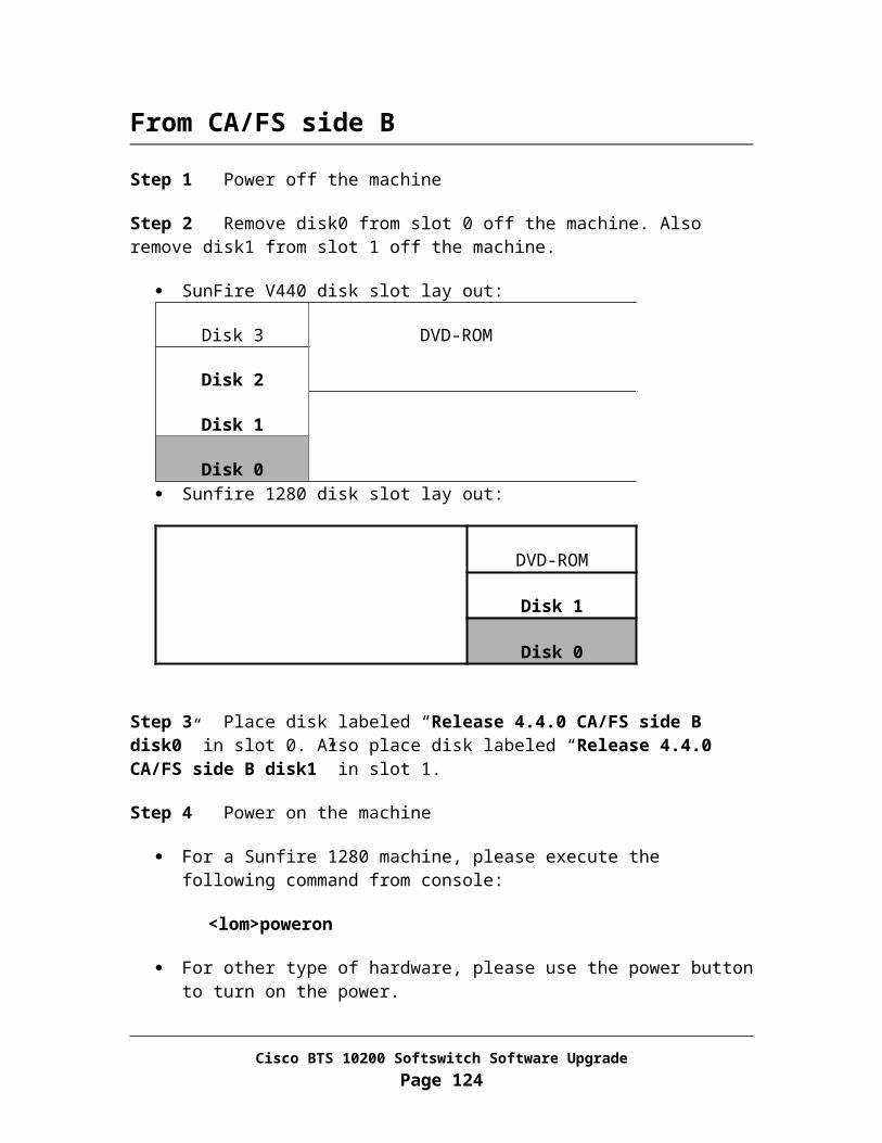
Appendix ICORBA InstallationThis procedure describes how to install the Common Object Request Broker Architecture (CORBA) application on Element Management System (EMS) of the Cisco BTS 10200 Softswitch.
Note This installation process is used for both side A and side B EMS.
Caution This CORBA installation will remove existing CORBA application on EMS machines. Once you have executed this procedure, there is no backout. Do not start this procedure until you have proper authorization. If you have questions, please contact Cisco Support.
Task 1: Open Unix Shell on EMS
Perform these steps to open a Unix shell on EMS.
Step 1 Ensure that your local PC or workstation has connectivity via TCP/IP to communicate with EMS units.
Step 2 Open a Unix shell or a XTerm window.
Note If you are unable to open a Xterm window, please contact you system administrator immediately.
Task 2: Install OpenORB CORBA Application
Remove Installed OpenORB Application
Step 1 Log in as root to EMS
Step 2 Enter the following command to remove the existing OpenORB package:
Cisco BTS 10200 Softswitch Software UpgradePage 124

<hostname># pkgrm BTScis
Respond with a “y” when prompted
<hostname># pkgrm BTSoorb
Respond with a “y” when prompted
Step 3 Enter the following command to verify that the CORBA application is removed:
<hostname># pgrep cis3
The system will respond by displaying no data, or by displaying an error message. This verifies that the CORBA application is removed.
Install OpenORB Packages
The CORBA application files are available for installation once the Cisco BTS 10200 Softswitch is installed.
Step 1 Log in as root to EMS
Note : If VIP was configured and recorded in the pre-upgrade step in Chapter 5 task 6 then, reconfigure the VIP on the Active EMS, otherwise, go to Step 3.
Step 2 Reconfigure VIP (Note that VIP needs to be configured on Active EMS (Side A)
<hostname> su - btsadmin
<btsadmin> change ems interface=<INTERFACE>;ip_alias=<VIP>
INTERFACE = Interface value recorded in chapter 5 , task 6
VIP = ip-alias value recorded in chapter 5, task 6
- Verify that VIP is configured
<btsadmin> show ems
IP_ALIAS=10.89.224.177INTERFACE=eri0NTP_SERVER=10.89.224.
<btsadmin> quit
Cisco BTS 10200 Softswitch Software UpgradePage 125

Step 3 <hostname># cd /opt/Build
Step 4 <hostname># cis-install.sh
The system will give several prompts before and during the installation process. Some prompts are repeated. Respond with a “y” when prompted.
Step 5 It will take about 5-8 minutes for the installation to complete.
Step 6 Verify CORBA Application is running On EMS:
<hostname># pgrep ins3
Note System will respond by displaying the Name Service process ID, which is a number between 2 and 32,000 assigned by the system during CORBA installation. By displaying this ID, the system confirms that the ins3 process was found and is running.
<hostname># pgrep cis3
Note The system will respond by displaying the cis3 process ID, which is a number between 2 and 32,000 assigned by the system during CORBA installation. By displaying this ID, the system confirms that the cis3 process was found and is running.
Step 7 If you do not receive both of the responses described in Step 5, or if you experience any verification problems, do not continue. Contact your system administrator. If necessary, call Cisco Support for additional technical assistance.
Cisco BTS 10200 Softswitch Software UpgradePage 126

Appendix JBlock Provisioning Path
From EMS side A and B
Make sure the provisioning path is blocked.
Step 1 Terminate all existing CLI sessions:
<hostname># pkill cli.sh
Step 2 Disable bulk provisioning:
<hostname># cd /opt/ems/bin
<hostname># echo "update PlatformPrograms set enable='N' where id='DLP';" | mysql_cli.sh
<hostname># pkill smg
Step 3 Check to see if CORBA is installed:
<hostname># grep –w cis3 /etc/inittab
If no results returned, please skip over the rest of the steps
Step 4 Disable CORBA:
<hostname># pkgrm BTScis
<hostname># pkgrm BTSoorb
<hostname># ps –ef |grep –i D_CIS |grep –v grep|awk ‘{print $2;}’
The output of the above command may display the process ID of one or more orphaned processes that need to be killed. If the PID is displayed, kill each of the process individually using the command below.
<hostname># kill -9 PID
Cisco BTS 10200 Softswitch Software UpgradePage 127

<hostname># ps –ef |grep –i D_INS |grep –v grep|awk ‘{print $2;}’
The output of the above command may display the process ID of one or more orphaned processes that need to be killed. If the PID is displayed, kill each of the process individually using the command below
<hostname># kill -9 PID
Cisco BTS 10200 Softswitch Software UpgradePage 128

Appendix KFiles handled by DoTheChange script
The following file list is FTPed from mate as the first execution step after replacing disks with new release:
resolv.conf netmasks TIMEZONE Defaultdomain hostname.* passwd shadow group users.tar ntp.conf S96StaticRoutes
The following file list is modified with either new hostname or to preserve existing user accounts in the system:
/etc/opticall.cfg /etc/nodetype /etc/hostname.* /etc/nodename /etc/hosts /etc/resolv.conf /etc/passwd /etc/shadow /etc/group /etc/TIMEZONE /etc/defaultdomain /etc/rc3.d/S96StaticRoutes /etc/inet/netmasks /etc/inet/ipsecinit.conf /etc/snmp/conf/snmpd.conf /opt/BTSxntp/etc/ntp.conf /opt/BTSossh/etc/sshd_config /opt/SMCapache/conf/httpd.conf /opt/SMCapache/conf/ssl.crt/*.crt /opt/SMCapache/conf/ssl.crt/*.key
Cisco BTS 10200 Softswitch Software UpgradePage 129
/opt/BTSoorb/config/OpenORB.xml /opt/BTSoorb/config/OpenORB-INS.xml /opt/ems/etc/ems.props /opt/oracle/admin/etc/listener.ora /opt/oracle/admin/etc/tnsnames.ora /opt/oracle/admin/etc/protocol.ora /opt/BTSordba/etc/dba.properties /opt/BTSoramg/etc/ora.properties /opt/ems/bin/platform.cfg /opt/bdms/bin/platform.cfg
Cisco BTS 10200 Softswitch Software UpgradePage 130

Appendix LDisable and Enable Radius Server
Task 1: Disable Radius Server
From Each Machine
Step 1 Log in as root. If root access is disabled, log in as an admin user.
Step 2 <hostname># vi /etc/pam.conf
Search for the line end with: /usr/lib/security/pam_radius_auth.so.1 Put the sign “#” at beginning of the line Save the file
Task 2: Enable Radius Server
From Each Machine
Step 1 Log in as root
Step 2 <hostname># vi /etc/pam.conf
Search for the line end with: /usr/lib/security/pam_radius_auth.so.1 Remove the sign “#” at beginning of the line Save the file
Cisco BTS 10200 Softswitch Software UpgradePage 131

Appendix MInstall IP01 Patch on EMS Step 1 Locate CD-ROM Disc labeled as " BTS_04_05_01_V24_IP01”
Log in as root Put Disc labeled as " BTS_04_05_01_V24_IP01” in the CD-ROM drive Mount CD-ROM drive
<hostname># cd /<hostname># mkdir -p /cdrom<hostname># mount -o ro -F hsfs /dev/dsk/c0t0d0s0 /cdrom
Copy file from the CD-ROM to the /opt directory.
<hostname># cp –f /cdrom/ BTS_04_05_01_V24_IP01.tar /opt<hostname># umount /cdrom
Manually eject the CD-ROM and take out Disc from drive
Step 2 Untar the file on EMS platform.
<hostname># cd /opt<hostname># tar -xvf /opt/BTS_04_05_01_V24_IP01.tar
Step 3 Update PatchLevel<hostname># cp /opt/BTS_04_05_01_V24_IP01/PatchLevel /opt/ems/utils<hostname># date >> /opt/ems/utils/PatchLevel
Cisco BTS 10200 Softswitch Software UpgradePage 132

Appendix NInstall IP01 Patch on CA Step 1 Locate CD-ROM Disc labeled as "BTS_04_05_01_V24_IP01"
Log in as root Put Disc labeled as " BTS_04_05_01_V24_IP01” in the CD-ROM drive Mount CD-ROM drive
<hostname># cd /<hostname># mkdir -p /cdrom<hostname># mount -o ro -F hsfs /dev/dsk/c0t0d0s0 /cdrom
Copy file from the CD-ROM to the /opt directory.
<hostname># cp –f /cdrom/ BTS_04_05_01_V24_IP01.tar /opt<hostname># umount /cdrom
Manually eject the CD-ROM and take out Disc from drive
Step 2 Untar the file on CA platform.
<hostname># cd /opt<hostname># tar -xvf /opt/BTS_04_05_01_V24_IP01.tar
Step 3 Verify the checksum for each file is valid
<hostname># cd /opt/BTS_04_05_01_V24_IP01<hostname># cksum libSIS.so.BTS_04_05_01_V24_IP01<hostname># cksum sga.BTS_04_05_01_V24_IP01
Output must match the checksums shown in BTS_04_05_01_V24_IP01.cksum
Step 4 Ensure the file has execute permission
<hostname># chmod +x libSIS.so.BTS_04_05_01_V24_IP01<hostname># chmod +x sga.BTS_04_05_01_V24_IP01
Step 5 Ensure the file has the correct owner and group<hostname># chown oamp:staff libSIS.so.BTS_04_05_01_V24_IP01
Step 6 Backup the original files and put the patches in place.
Cisco BTS 10200 Softswitch Software UpgradePage 133

<hostname>cd /opt/BTSlib/lib<hostname>cp -p libSIS.so libSIS.so.IP01<hostname>cp -p
/opt/BTS_04_05_01_V24_IP010/libSIS.so.BTS_04_05_01_V24_IP01 libSIS.so
<hostname>cd /opt/Opticall/ca/bin<hostname> cp -p
/opt/BTS_04_05_01_V24_IP01/sga.BTS_04_05_01_V24_IP01 sga.BTS_04_05_01_V24_IP01
<hostname> cd /opt/OptiCall/CAxxx/bin<hostname> rm sga.CAxxx
<hostname> ln –s /opt/OptiCall/ca/bin/sga.BTS_04_05_01_V24_IP01 sga.CAxxx
Step 7 Update PatchLevel on CA
<hostname># cp /opt/BTS_04_05_01_V24_IP01/PatchLevel /opt/ems/utils<hostname># date >> /opt/ems/utils/PatchLevel
Backout Procedure for IP01 Patch.
In the steps below CAxxx must be replaced with the appropriate CA instance number for the system being patched. If you are unsure of the instance number run the "nodestat" command to find the instance number.
This section of the backout procedure assumes the CAxxx application is active on the primary side before you begin the patch backout.
Step 1 Stop the CA application on the Secondary CA
<hostname>#platform stop all
Step 2 Reinstall the saved files (before patching).
<hostname>#cd /opt/BTSlib/lib
<hostname>#mv libSIS.so.IP01 libSIS.so
<hostname>#cd /opt/OptiCall/CAxxx/bin<hostname>#rm sga.CAxxx
Cisco BTS 10200 Softswitch Software UpgradePage 134

<hostname>#ln –s /opt/OptiCall/ca/bin/sga sga.CAxxx
Step 3 On the secondary CA
<hostname>#mv /opt/ems/utils/PatchLevel.IP01 /opt/ems/utils/PatchLevel Step 4 Start the secondary CA. Wait 10 minutes for the platform to stabilize and force it to active
<hostname>#platform start all
CAUTION: Wait 10 minutes before executing Step 5
Step 5 Login to the CLI as “btsuser”
<hostname># su – btsuser
CLI> control call-agent id=CAxxx; target-state=standby_activeCLI> control feature-server id=FSPTCyyy; target-state=standby_activeCLI> control feature-server id=FSAINzzz; target-state=standby_active
Step 6. Perform test calls. If all goes well repeat steps 2, 3, 4 and 5 on the primary CA , and return the system to normal operating mode with the following commands...
CLI> control call-agent id=CAxxx; target-state=active_standbyCLI> control feature-server id=FSPTCyyy; target-state=active_standbyCLI> control feature-server id=FSAINzzz; target-state=active_standby
Step 7. On the primary EMS
<hostname>#cd /opt/ems/utils<hostname>#mv PatchLevel.IP01 PatchLevel
Step 8. On the secondary EMS
<hostname>#cd /opt/ems/utils<hostname>#mv PatchLevel.IP01 PatchLevel
Cisco BTS 10200 Softswitch Software UpgradePage 135

Cisco BTS 10200 Softswitch Software UpgradePage 136
Related Documents