LINEAR DC POWER SUPPLY 1/50

chapter 1 linear dc power supply
Aug 12, 2015
Welcome message from author
This document is posted to help you gain knowledge. Please leave a comment to let me know what you think about it! Share it to your friends and learn new things together.
Transcript

LINEAR DC POWER SUPPLY
1/50

2/50
i. All electronic circuits need power source to function.
ii. Power Supply Unit is a device used to convert, regulate and transmit the required power to the circuit to be operated.
iii. Electronic circuits made up of semiconductors need specific value of Direct Current (DC) voltage.
iv. Batteries are common DC voltage source for electronic equipment especially portables like cell phones and iPods.
v. Most non-portable equipment uses power supplies that operate from the AC power line but produce one or more DC outputs.
Click to “Play” the Video
3/50
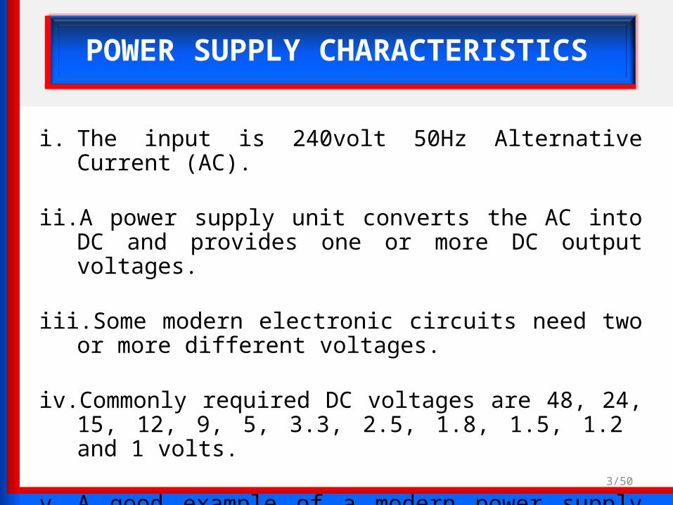
POWER SUPPLY CHARACTERISTICS
i. The input is 240volt 50Hz Alternative Current (AC).
ii. A power supply unit converts the AC into DC and provides one or more DC output voltages.
iii. Some modern electronic circuits need two or more different voltages.
iv. Commonly required DC voltages are 48, 24, 15, 12, 9, 5, 3.3, 2.5, 1.8, 1.5, 1.2 and 1 volts.
v. A good example of a modern power supply is the one inside a PC that furnishes 12, 5, 3.3 and 1.2 volts.

4/50

5/50
The operation of a DC power supply circuit
The importance of DC power supply units in electronic appliances
i. Power supply provide one or more fixed voltages with sufficient current to the operating circuit.
ii. Electronic devices such as transistor radio, television and video cd players operate fully or partly on DC power supply in the range of 0 to 24V.
iii. The successful operation of the device depends on the proper function of the DC power supply. The power supply tries to provide a smooth, constant DC voltage, as required by an electronic device.
iv. Major electronic appliances have built-in electronic circuits that take power from a wall socket and convert it to the form and voltages required by the other internal circuits of the appliance.
6/50
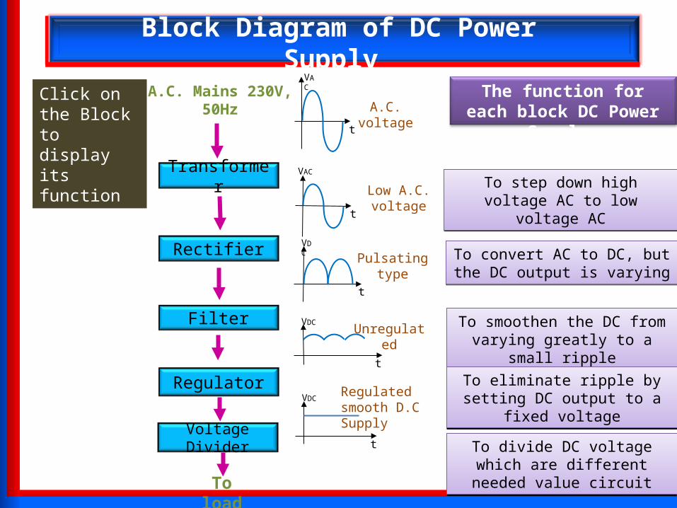
Block Diagram of DC Power Supply
To load
VDC
t
Regulated smooth D.C Supply
Regulator
A.C. Mains 230V, 50Hz A.C. voltage
VAC
t
Rectifier Pulsating typeVDC
t
FilterUnregulated
VDC
t
Voltage Divider
Transformer VAC
t
Low A.C. voltage To step down high voltage AC to low voltage AC
To step down high voltage AC to low voltage AC
To convert AC to DC, but the DC output is varying
To convert AC to DC, but the DC output is varying
To smoothen the DC from varying greatly to a small ripple
To smoothen the DC from varying greatly to a small ripple
To eliminate ripple by setting DC output to a fixed voltageTo eliminate ripple by setting DC output to a fixed voltage
To divide DC voltage which are different needed value circuit
To divide DC voltage which are different needed value circuit
The function for each block DC Power Supply
Click on the Block to display its function

7/50
Transformer
TransformerTransformer
Symbol
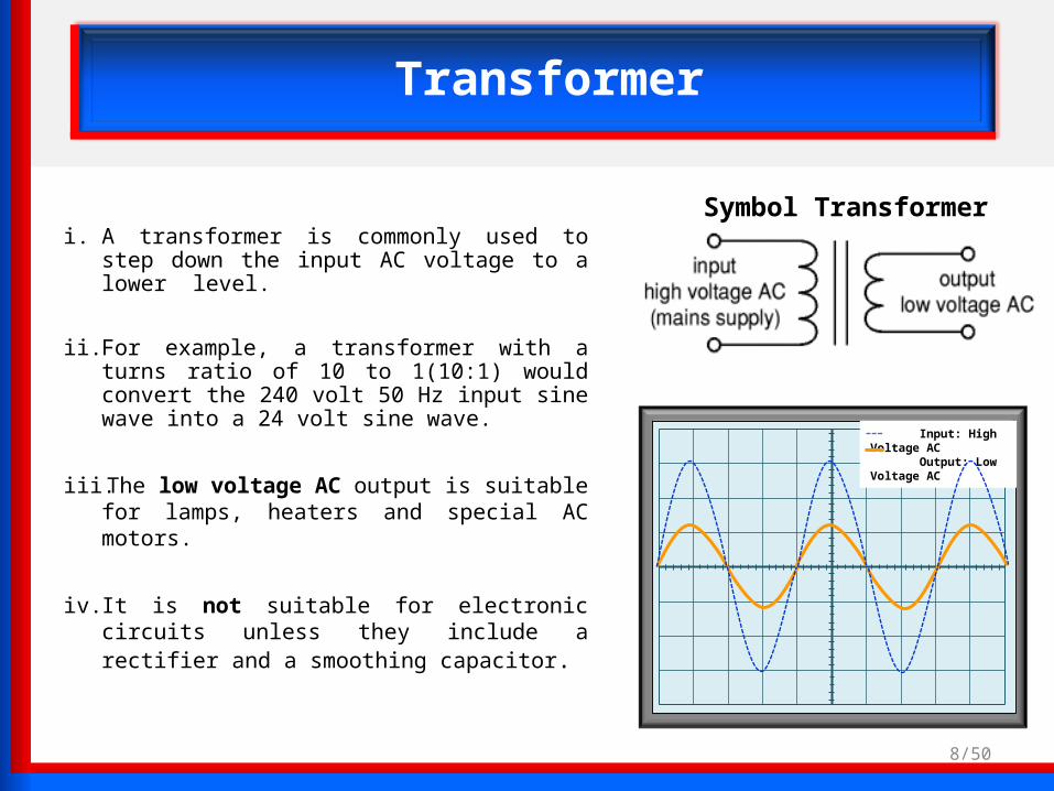
Input: High Voltage AC Output: Low Voltage AC
Transformer
i. A transformer is commonly used to step down the input AC voltage to a lower level.
ii. For example, a transformer with a turns ratio of 10 to 1(10:1) would convert the 240 volt 50 Hz input sine wave into a 24 volt sine wave.
iii. The low voltage AC output is suitable for lamps, heaters and special AC motors.
iv. It is not suitable for electronic circuits unless they include a rectifier and a smoothing capacitor.
Symbol Transformer
8/50

9/50
Transformer + Rectifier
TransformerTransformer RectifierRectifier
10/50
Transformer + Rectifier
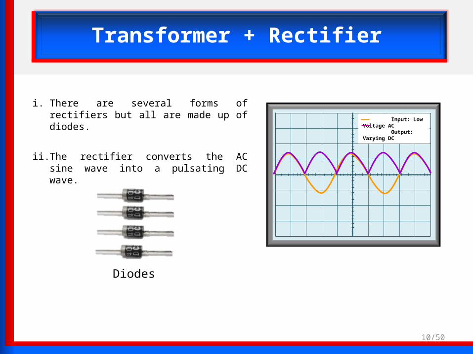
i. There are several forms of rectifiers but all are made up of diodes.
ii. The rectifier converts the AC sine wave into a pulsating DC wave.
Input: Low Voltage AC Output: Varying DC
Diodes
Input: Low Voltage AC Output: Varying DC
Input: Low Voltage AC Output: Varying DC
11/50
Transformer + Rectifier
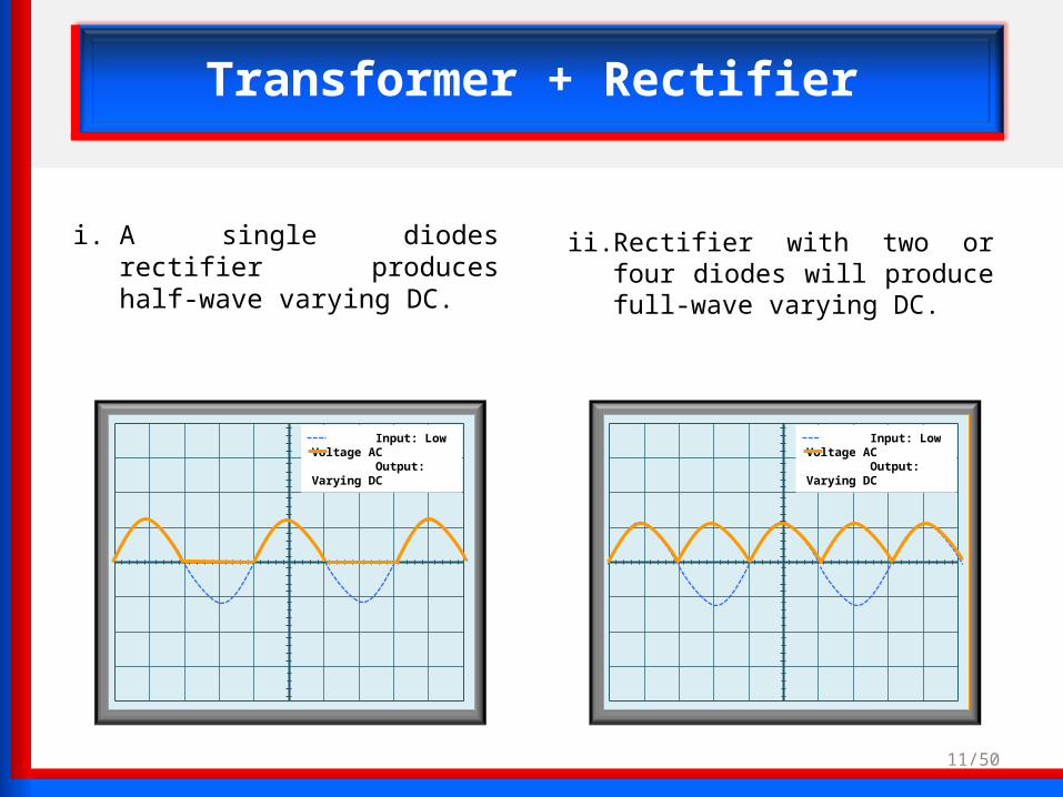
i. A single diodes rectifier produces half-wave varying DC.
ii. Rectifier with two or four diodes will produce full-wave varying DC.

12/50
Transformer + Rectifier + Filter
TransformerTransformer RectifierRectifier FilterFilter
13/50
Transformer + Rectifier + Filter
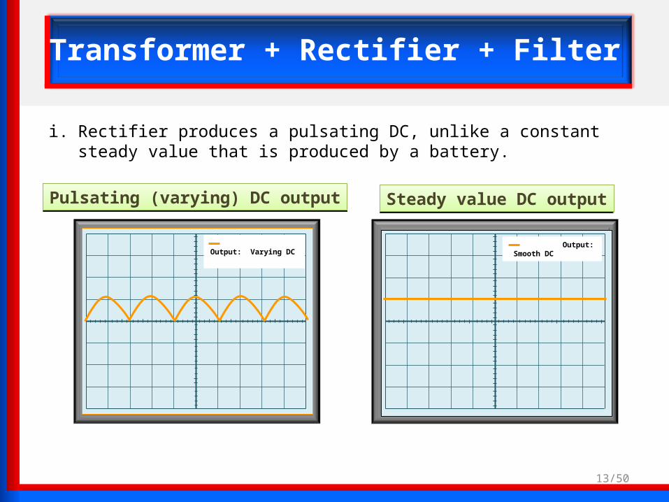
i. Rectifier produces a pulsating DC, unlike a constant steady value that is produced by a battery.
Output: Smooth DC
Output: Varying DC
Pulsating (varying) DC outputPulsating (varying) DC output Steady value DC outputSteady value DC output

Input: Varying DC Output: Smooth DC
14/50
Transformer + Rectifier + Filter
ii. A filter is then used to remove the pulsations and create a constant output.
Output: Varying DC
Pulsating (varying) DC outputPulsating (varying) DC output Constant / Smooth DC outputConstant / Smooth DC output
15/50
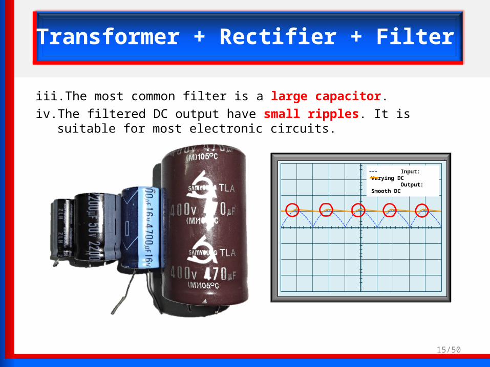
Transformer + Rectifier + Filter
iii. The most common filter is a large capacitor.
iv. The filtered DC output have small ripples. It is suitable for most electronic circuits.
Input: Varying DC Output: Smooth DC

RectifierRectifier
16/50
Transformer + Rectifier + Filter+ Regulator
TransformerTransformer FilterFilter RegulatorRegulator

Input: Smooth DC Output: Regurated DC
17/50
Transformer + Rectifier + Filter+ Regulator
i. The regulator is a component that helps to maintain a fixed or constant output voltage.
RegulatorRegulator

Input: Smooth DC Output: Regurated DC
18/50
Transformer + Rectifier + Filter+ Regulator
ii. Changes in the load or the AC line voltage will cause the output voltage to vary.
Input: Smooth DC Output: Regurated DC

19/50
Transformer + Rectifier + Filter+ Regulator
iii. Most electronic circuits cannot withstand the variations since they are designed to work properly with a fixed voltage.
iv. The regulator fixes the output voltage to the desired level and maintains that value despite any output or input variations.
v. The regulated DC output is very smooth with no ripples. It is suitable for all electronic circuits.
Input: Smooth DC Output: Regurated DC
DC output is very smooth with no ripple

20/50
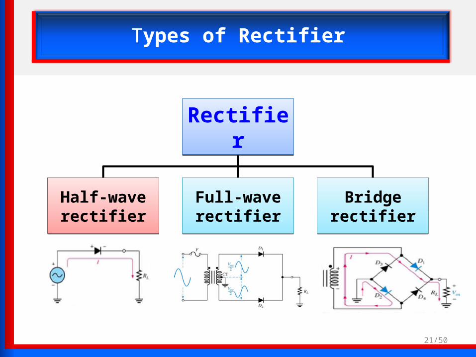
Types of Rectifier
RectifierRectifier
Half-wave rectifier
Half-wave rectifier
Full-wave rectifier
Full-wave rectifier
Bridge rectifierBridge rectifier
21/50
Types of Rectifier
RectifierRectifier
Full-wave rectifier
Full-wave rectifier
Bridge rectifierBridge rectifier
Half-wave rectifier
Half-wave rectifier
22/50
HALF-WAVE RECTIFIER
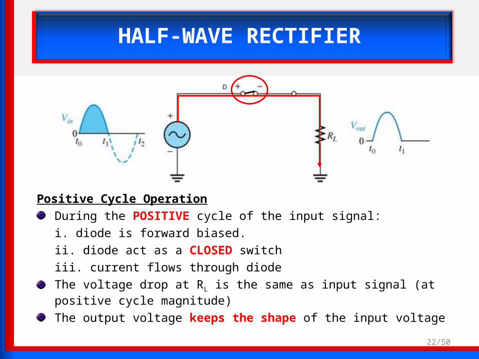
Positive Cycle Operation
During the POSITIVE cycle of the input signal:
i. diode is forward biased.
ii. diode act as a CLOSED switch
iii. current flows through diode
The voltage drop at RL is the same as input signal (at positive cycle magnitude)
The output voltage keeps the shape of the input voltage

23/50
HALF-WAVE RECTIFIER
Negative cycle operation
During the NEGATIVE cycle of input signal:
i. the D diode is reverse biased
ii. Diode act as OPEN switch
iii. no current flow through diode
The voltage drop at RL is zero.
VL = 0 V
I = 0 ANEGATIVE Cycle

24/50
HALF-WAVE RECTIFIER
Calculation of output voltage Output voltage for the half-wave rectifier circuit is for the positive cycle only.
Example : Vin = 20 V Vout = Vin – 0.7V(silicon diode)
= 20V – 0.7V = 19.3V The output signal frequency is same frequency as input.
Vout Vin = 20 V
Vin = 20 V
Vout = 19.3 V
0.7V(silicon diode)
25/50
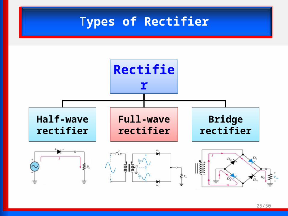
Types of Rectifier
RectifierRectifier
Half-wave rectifier
Half-wave rectifier
Bridge rectifierBridge rectifier
Full-wave rectifier
Full-wave rectifier

FULL-WAVE RECTIFIER
i. A full-wave rectifier is exactly the same as the half-wave rectifierii. It use 2 diodes, D1 and D2
iii. It allows unidirectional current flow through the load during the entire sinusoidal cycle (as opposed to only half the cycle in the half-wave)
Full-wave Rectifier Output Signal
AC input Signal
26/50
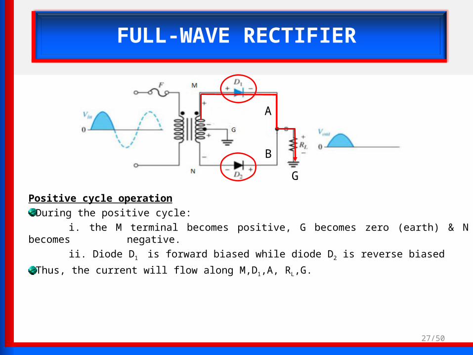
FULL-WAVE RECTIFIER
Positive cycle operation
During the positive cycle:
i. the M terminal becomes positive, G becomes zero (earth) & N becomes negative.
ii. Diode D1 is forward biased while diode D2 is reverse biased
Thus, the current will flow along M,D1,A, RL,G.
A
B
G
27/50

FULL-WAVE RECTIFIER
Negative cycle operation
During the NEGATIVE cycle:
i. M terminal becomes negative, G becomes zero (earth) and N becomes positive.
ii. D2 is forward biased, while D1 is reverse biased
iii. Thus , the current will flow along N, D2, C, B, RL, G.
OUTPUT wave is always POSITIVE because the current that flows through RL (load) is same direction for both the positive and negative cycle.
c
28/50

FULL-WAVE RECTIFIER
Output signal negative cycle
Output Voltage is formed at both cycle.Frequency of output is twice of the input frequency.
Output Voltage
29/50

30/50
Types of Rectifier
RectifierRectifier
Half-wave rectifier
Half-wave rectifier
Full-wave rectifier
Full-wave rectifier
Bridge rectifierBridge rectifier

BRIDGE RECTIFIER
Positive Cycle OperationBridge rectifier use four diodes, D1, D2, D3 and D4During the POSITIVE input cycle :i. D1 and D2 diodes are forward biased
ii. D3 and D4 are reverse biased
The current will flow along G, D, D2, C, N, M, A, D1,B, RL,G.
31/50
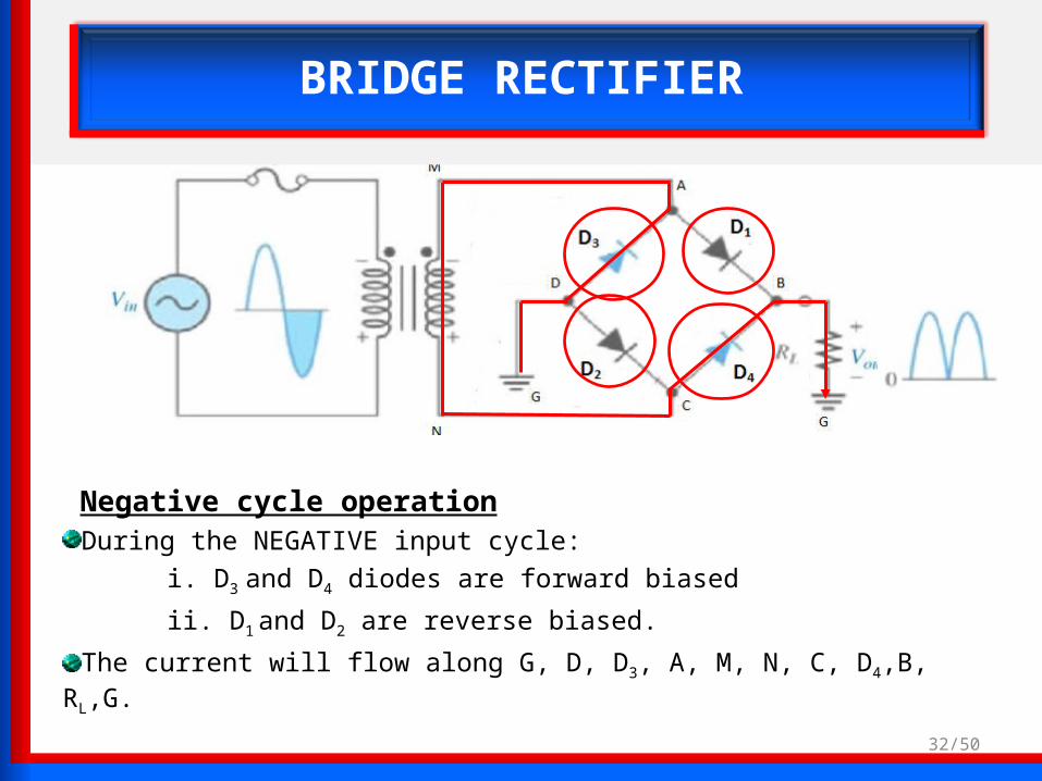
BRIDGE RECTIFIER
Negative cycle operationDuring the NEGATIVE input cycle:
i. D3 and D4 diodes are forward biased
ii. D1 and D2 are reverse biased.
The current will flow along G, D, D3, A, M, N, C, D4,B, RL,G.
32/50

BRIDGE RECTIFIER
Output voltage
33/50Notes: PIV is Peak Inverse Voltage.
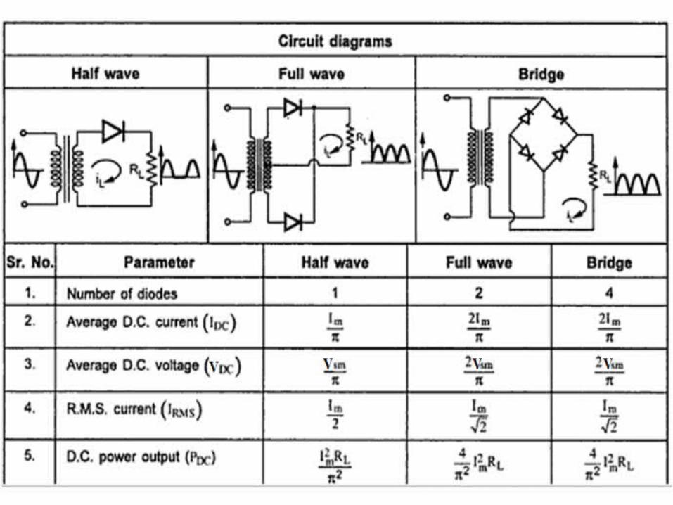

Comparison between two diodes rectifier and four diodes rectifier
FilterFilter
( Vr )p-p
Va.t.
Va.t.
V
t
V
t
Figure 5.5.2 : Pure DC voltage Figure 5.5.3:Ripple DC voltage
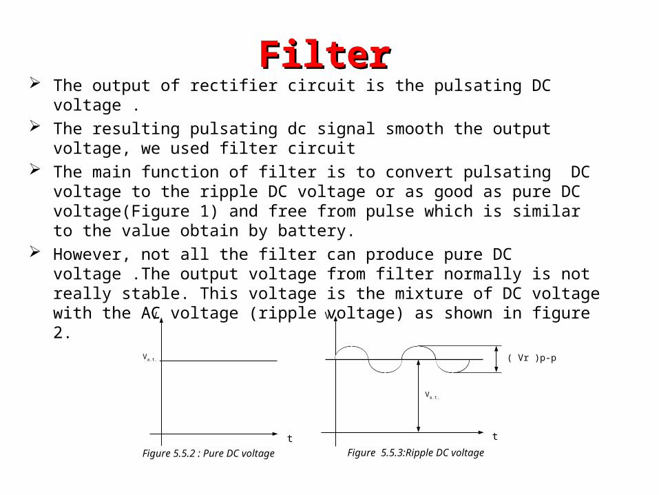
The output of rectifier circuit is the pulsating DC voltage . The resulting pulsating dc signal smooth the output voltage, we used filter circuit The main function of filter is to convert pulsating DC voltage to the ripple DC
voltage or as good as pure DC voltage(Figure 1) and free from pulse which is similar to the value obtain by battery.
However, not all the filter can produce pure DC voltage .The output voltage from filter normally is not really stable. This voltage is the mixture of DC voltage with the AC voltage (ripple voltage) as shown in figure 2.

Types FilterTypes Filter
• The best filter circuit is the filter that can decrease as much as the value of Vr p-p produce by ripple DC voltage .The other type of filter are
1. Capacitor filter2. RC filter3. LC filter4. Π- Type Filter

1.5 RC filter
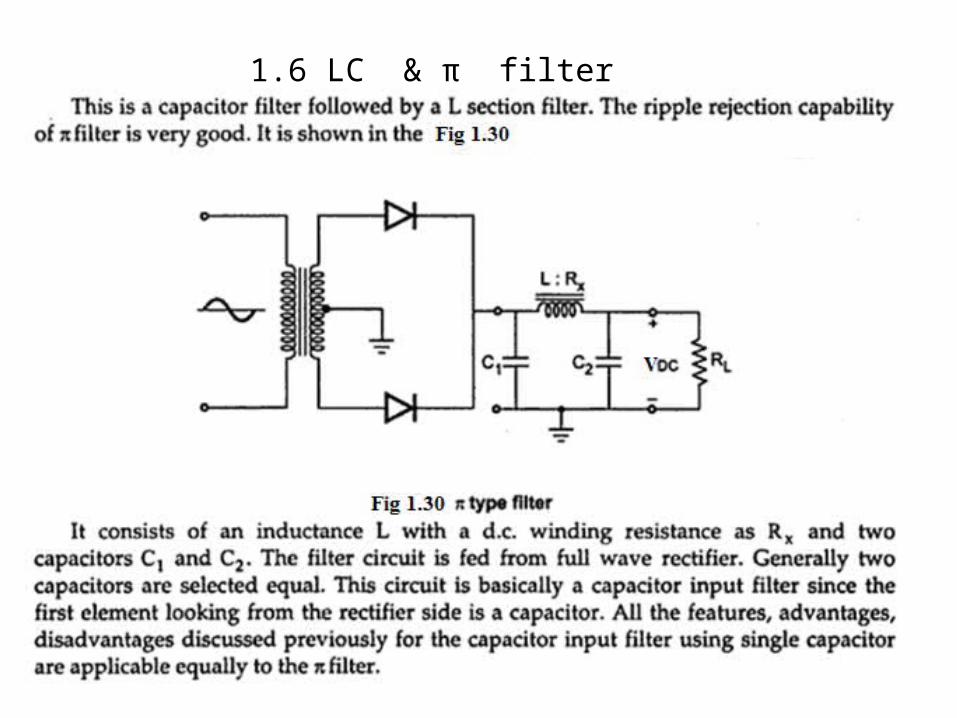
1.6 LC & π filter

1.7 Voltage Regulator1.7.1 The voltage regulator circuits construct by using Zener
diode
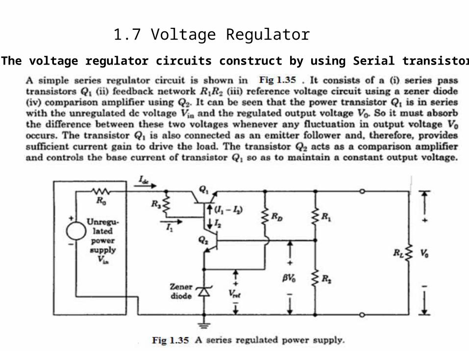
1.7 Voltage Regulator
1.7.3 The voltage regulator circuits construct by using Serial transistor
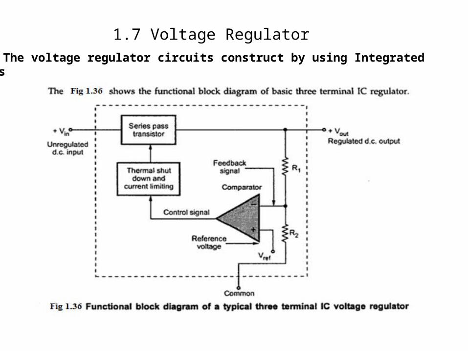
1.7 Voltage Regulator1.7.3 The voltage regulator circuits construct by using Integrated
Circuits

1.8 Voltage DividerVoltage divider rule is a simple way of determining the output voltage across one of two impedances connected in series

1.9 1.9 The schematic diagrams of a simple power supply unit which includes full-wave rectifier, filter and Zener
diode voltage regulator.

46
1.9 1.9 The schematic diagrams of a simple power supply unit which includes full-wave rectifier, filter and IC voltage regulator.

47
1.9 1.9 The schematic diagrams of a simple power supply unit which includes Bridge rectifier, filter and IC voltage regulator.
EE3110 Oscillator 48
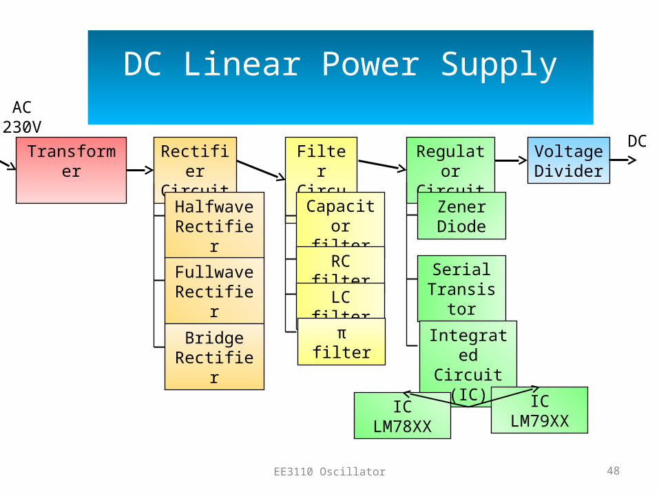
DC Linear Power Supply
Rectifier Circuit
Filter Circuit
Regulator Circuit
Voltage Divider
Transformer
Halfwave Rectifier
Fullwave Rectifier
Bridge Rectifier
Capacitor filter
RC filter
LC filter
π filter
Zener Diode
Serial Transistor
Integrated Circuit (IC)
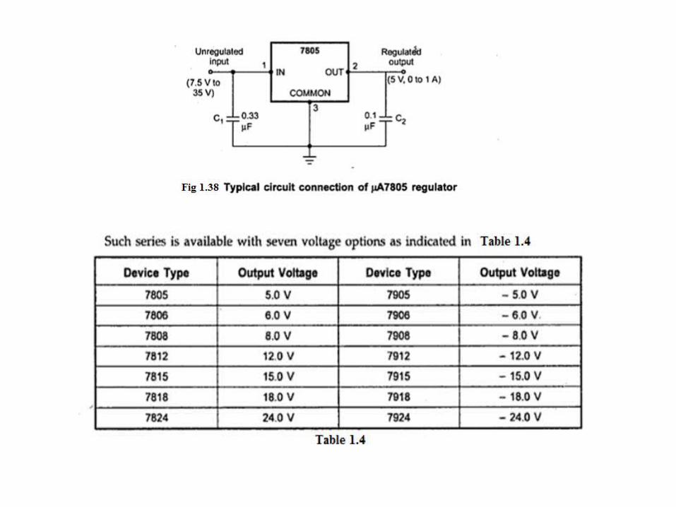
IC LM78XX
IC LM79XX
AC 230V
DC
Related Documents


![[Note] Chapter 1 - Linear DC Power Supply](https://static.cupdf.com/doc/110x72/553299b255034687698b4651/note-chapter-1-linear-dc-power-supply.jpg)