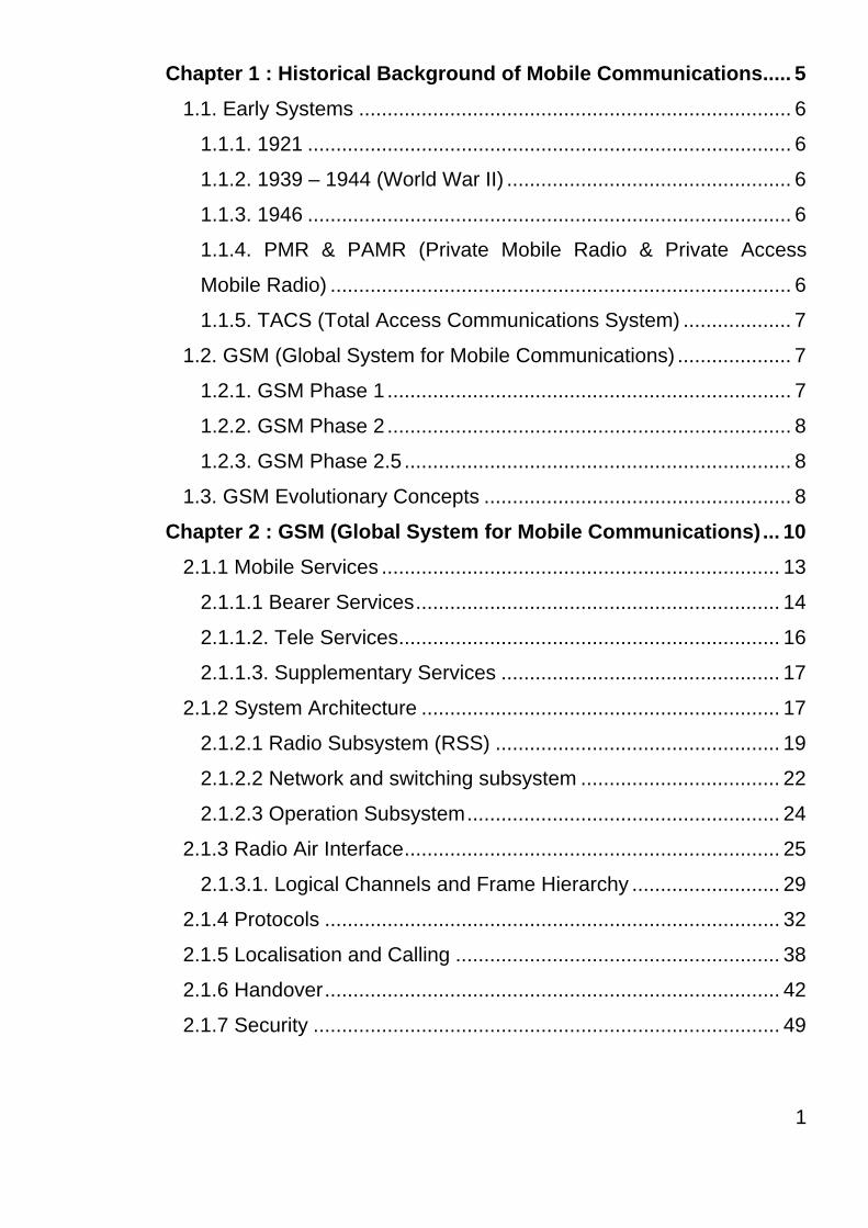
Chapter 1 : Historical Background of Mobile Communications..... 5 1.1. Early Systems ............................................................................ 6 1.1.1. 1921 ..................................................................................... 6 1.1.2. 1939 – 1944 (World War II) .................................................. 6 1.1.3. 1946 ..................................................................................... 6 1.1.4. PMR & PAMR (Private Mobile Radio & Private Access Mobile Radio) ................................................................................. 6 1.1.5. TACS (Total Access Communications System) ................... 7 1.2. GSM (Global System for Mobile Communications) .................... 7 1.2.1. GSM Phase 1 ....................................................................... 7 1.2.2. GSM Phase 2 ....................................................................... 8 1.2.3. GSM Phase 2.5 .................................................................... 8 1.3. GSM Evolutionary Concepts ...................................................... 8 Chapter 2 : GSM (Global System for Mobile Communications) ... 10 2.1.1 Mobile Services ...................................................................... 13 2.1.1.1 Bearer Services ................................................................ 14 2.1.1.2. Tele Services................................................................... 16 2.1.1.3. Supplementary Services ................................................. 17 2.1.2 System Architecture ............................................................... 17 2.1.2.1 Radio Subsystem (RSS) .................................................. 19 2.1.2.2 Network and switching subsystem ................................... 22 2.1.2.3 Operation Subsystem ....................................................... 24 2.1.3 Radio Air Interface.................................................................. 25 2.1.3.1. Logical Channels and Frame Hierarchy .......................... 29 2.1.4 Protocols ................................................................................ 32 2.1.5 Localisation and Calling ......................................................... 38 2.1.6 Handover ................................................................................ 42 2.1.7 Security .................................................................................. 49 1

Welcome message from author
This document is posted to help you gain knowledge. Please leave a comment to let me know what you think about it! Share it to your friends and learn new things together.
Transcript
Chapter 1 : Historical Background of Mobile Communications..... 5
1.1. Early Systems ............................................................................ 6
1.1.1. 1921 ..................................................................................... 6
1.1.2. 1939 – 1944 (World War II) .................................................. 6
1.1.3. 1946 ..................................................................................... 6
1.1.4. PMR & PAMR (Private Mobile Radio & Private Access
Mobile Radio) ................................................................................. 6
1.1.5. TACS (Total Access Communications System) ................... 7
1.2. GSM (Global System for Mobile Communications) .................... 7
1.2.1. GSM Phase 1 ....................................................................... 7
1.2.2. GSM Phase 2 ....................................................................... 8
1.2.3. GSM Phase 2.5 .................................................................... 8
1.3. GSM Evolutionary Concepts ...................................................... 8
Chapter 2 : GSM (Global System for Mobile Communications) ... 10
2.1.1 Mobile Services ...................................................................... 13
2.1.1.1 Bearer Services................................................................ 14
2.1.1.2. Tele Services................................................................... 16
2.1.1.3. Supplementary Services ................................................. 17
2.1.2 System Architecture ............................................................... 17
2.1.2.1 Radio Subsystem (RSS) .................................................. 19
2.1.2.2 Network and switching subsystem ................................... 22
2.1.2.3 Operation Subsystem....................................................... 24
2.1.3 Radio Air Interface.................................................................. 25
2.1.3.1. Logical Channels and Frame Hierarchy .......................... 29
2.1.4 Protocols ................................................................................ 32
2.1.5 Localisation and Calling ......................................................... 38
2.1.6 Handover................................................................................ 42
2.1.7 Security .................................................................................. 49
1

2.1.7.1 Authentication................................................................... 51
2.1.7.2 Encryption. ....................................................................... 53
Chapter Summary and key Points................................................... 55
Chapter 3 : EDGE (Enhanced Data rates for GSM Evolution) ...... 59
3.1 The Evolution of the GSM Network ........................................... 60
3.2 High Speed Circuit Switched Data (HSCSD) ............................ 62
3.3 General Packet Radio Service (GPRS)..................................... 65
3.3.1 System Overview ................................................................ 65
3.4 Traffic Cases ............................................................................. 73
3.4.1 IMSI attach .......................................................................... 73
3.4.2 GPRS Attach....................................................................... 74
3.4.3 Combined GPRS/IMSI Attach ............................................. 75
3.4.4 PDP Context Activation and Deactivation ........................... 76
3.5 GPRS Air Interface.................................................................... 76
3.6 Logical Channels....................................................................... 77
3.7 PDCH Allocation........................................................................ 78
3.7.1 Dedicated PDCH................................................................. 79
3.7.2 On-demand PDCH .............................................................. 80
3.7.3 Master PDCH ...................................................................... 80
3.8 Cell Selection and Reselection.................................................. 80
3.8.1 GPRS Support Node (GSN)................................................ 83
3.9 Interconnection Principles. ........................................................ 83
3.10 GPRS IP Connectivity ............................................................. 84
3.11 The users IP communication. .................................................. 84
Chapter Summary and Key Points .................................................. 85
2
Chapter 4 : WCDMA (Wideband CDMA) ......................................... 874.1 WCDMA .................................................................................... 88
4.2 Carrier Spacing and Deployment Scenarios ............................. 89
4.3 Logical Channels....................................................................... 90
4.4 Control Channels....................................................................... 90
4.5 Uplink Physical Channels.......................................................... 91
4.6 Downlink Physical Channels ..................................................... 93
4.7 Packet Data............................................................................... 93
4.8 Handovers ................................................................................. 95
4.8.1 Soft Handovers.................................................................... 95
Chapter 5 : UMTS (Universal Mobile Telecommunication System)........................................................................................................... 98
5.1 UMTS Introduction .................................................................. 100
5.2 Horizontal Layering ................................................................. 101
5.3 General Principles ................................................................... 102
5.3.1 User Plane......................................................................... 102
5.3.2 Control Plane..................................................................... 104
5.3.3 Application Layer............................................................... 104
5.4 Core Network Standards and Interfaces ................................. 104
5.5 Key Benefits of the Layered Architecture ................................ 106
5.6 Core UMTS Network Elements ............................................... 108
5.8 Routers/Switches .................................................................... 116
5.9 Traffic Handling in a Layered Architecture .............................. 117
5.9.1 Traffic Cases ..................................................................... 117
3
Chapter 6 : The Future of Mobile Communications (10 years +) 1236.1 The Future............................................................................... 124
Chapter 7 Final Thoughts .............................................................. 125
7.1 Final Thoughts......................................................................... 126
7.2 The User:................................................................................. 126
7.3 The Operator: .......................................................................... 128
7.4 The Manufacturer: ................................................................... 128
7.5 The Winner:............................................................................. 129
8.0 Critique...................................................................................... 132
4

Chapter 1 : Historical Background of Mobile Communications
5
1.1. Early Systems
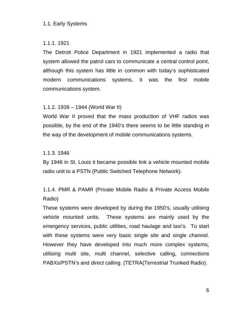
1.1.1. 1921
The Detroit Police Department in 1921 implemented a radio that
system allowed the patrol cars to communicate a central control point,
although this system has little in common with today’s sophisticated
modern communications systems, it was the first mobile
communications system.
1.1.2. 1939 – 1944 (World War II)
World War II proved that the mass production of VHF radios was
possible, by the end of the 1940’s there seems to be little standing in
the way of the development of mobile communications systems.
1.1.3. 1946
By 1946 in St. Louis it became possible link a vehicle mounted mobile
radio unit to a PSTN (Public Switched Telephone Network).
1.1.4. PMR & PAMR (Private Mobile Radio & Private Access Mobile
Radio)
These systems were developed by during the 1950’s, usually utilising
vehicle mounted units. These systems are mainly used by the
emergency services, public utilities, road haulage and taxi’s. To start
with these systems were very basic single site and single channel.
However they have developed into much more complex systems,
utilising multi site, multi channel, selective calling, connections
PABXs/PSTN’s and direct calling. (TETRA(Terrestrial Trunked Radio).
6

1.1.5. TACS (Total Access Communications System)
TACS was the first real mobile communications system*. In 1985
when this system was introduced it was mainly vehicle mounted units,
but later developed into mobile units. Unlike the other systems used
around the world TACS used the 900 MHz band.
* In the United Kingdom
1.2. GSM (Global System for Mobile Communications)
The concept for GSM started in 1982 when CEPT (Conference for
European Post and Telecommunications Administration) formed a
committee known as Groupe Speciale Mobile. The main reason for
the formation of this committee, was to create a standard for mobile
communications within Europe. This would have several distinct
advantages, such as the user would be able to use their phone
anywhere within Europe, and any manufacturer would be able to
produce any part of the overall system. When conceived GSM was
not envisaged as being a global standard.
In 1990 the design development of GSM was frozen into a set of
standards known as the “GSM Specifications”.
1.2.1. GSM Phase 1
The standardisation of GSM900 was completed in 1990 and of
DCS1800 in 1991. These standards are designated as GSM Phase 1,
they include all the central requirements for a digital cellular network.
Speech transmission (Full Rate Speech) is of central importance.
Data transfer is defined with rates of 0.3 up to 9.6 kbit/s. only a few
basic Supplementary Services (call forwarding and call baring) are
included.
7
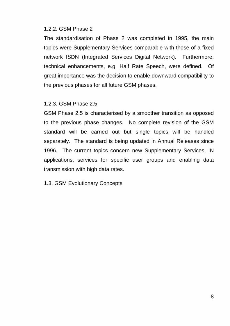
1.2.2. GSM Phase 2
The standardisation of Phase 2 was completed in 1995, the main
topics were Supplementary Services comparable with those of a fixed
network ISDN (Integrated Services Digital Network). Furthermore,
technical enhancements, e.g. Half Rate Speech, were defined. Of
great importance was the decision to enable downward compatibility to
the previous phases for all future GSM phases.
1.2.3. GSM Phase 2.5
GSM Phase 2.5 is characterised by a smoother transition as opposed
to the previous phase changes. No complete revision of the GSM
standard will be carried out but single topics will be handled
separately. The standard is being updated in Annual Releases since
1996. The current topics concern new Supplementary Services, IN
applications, services for specific user groups and enabling data
transmission with high data rates.
1.3. GSM Evolutionary Concepts
8
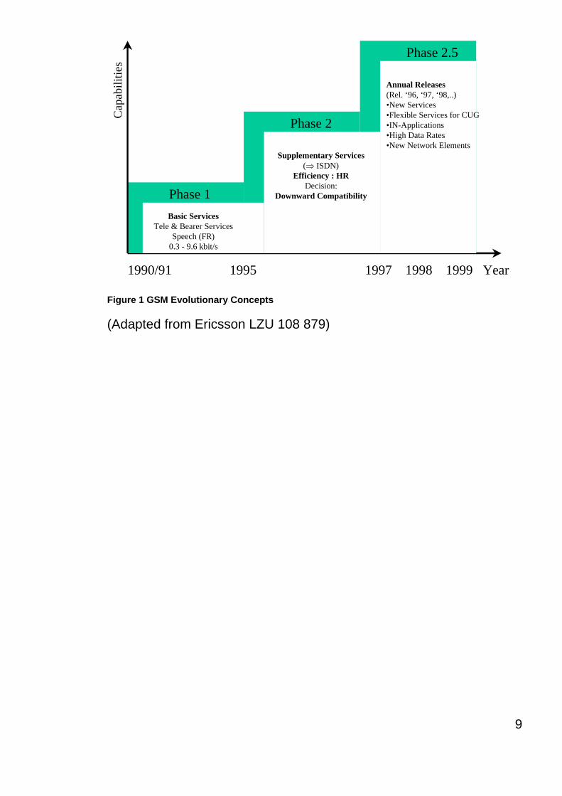
Phase 1
Phase 2
Phase 2.5
Basic ServicesTele & Bearer Services
Speech (FR)0.3 - 9.6 kbit/s
Supplementary Services(⇒ ISDN)
Efficiency : HRDecision:
Downward Compatibility
Annual Releases(Rel. ‘96, ‘97, ‘98,..)•New Services•Flexible Services for CUG•IN-Applications•High Data Rates•New Network Elements
1990/91 1995 1997 1998 1999 Year
Cap
abili
ties
Figure 1 GSM Evolutionary Concepts
(Adapted from Ericsson LZU 108 879)
9

Chapter 2 : GSM (Global System for Mobile Communications)
10

2.1 Introduction (GSM)
The most successful mobile digital communications system in today’s
world is GSM, with networks in over 130 countries and more than 100
million users worldwide. Back at the start of the 1980’s Europe was
facing a big problem, there were many existing analogue mobile
networks, which were based on similar standards, for example NMT
450, however they were all running on slightly different carrier
frequencies. To avoid this problem in the second generation mobile
phone system, the Groupe Spéciale Mobile (GSM) was created in
1982. Now the system developed by this group is known as global
system for mobile communications (GSM).
The primary goal of GSM was to provide a mobile phone system that
would allow it’s users to use their mobile phone in any European
country i.e. Roaming. This system would have to provide voice
services comparable with ISDN and other PSTN systems. The initial
specification details were over 5000 pages, with the new services in
particular data services there are even more specification details.
GSM is a typical second generation system, replacing the old
analogue first generation system, however it still does not offer
worldwide high data rates but will be offered in the new third
generation system UMTS. GSM was initially deployed in Europe using
the 890 – 915 MHz band for the uplinks and the 935 – 960 MHz band
for the downlinks. This version is commonly known as GSM 900, and
later version GSM 1800 (1710 – 1785MHz uplink, 1805 – 1880MHz
downlink) which commonly known as DCS (Digital Cellular System)
11
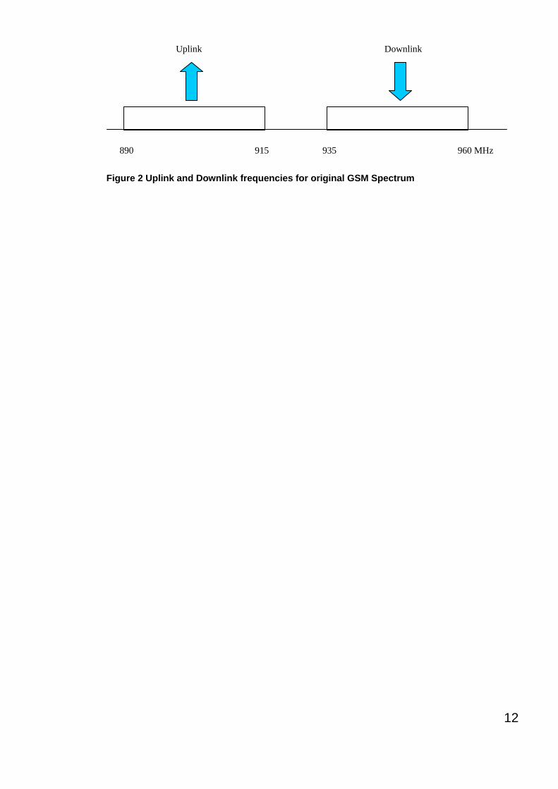
890 915 935 960 MHz
Uplink Downlink
Figure 2 Uplink and Downlink frequencies for original GSM Spectrum
12

2.1.1 Mobile Services
The GSM system permits the integration of different voice and data
services and the inter-working with existing networks. Services make
a network flexible to users, i.e. they can choose one network over
another. GSM has three different categories of services, bearer, tele
and supplementary services And these are described in the following
sections. Figure 3 shows a reference model for the GSM services.
GSM-PLMNtransit
network(PSTN, ISDN)
source/destination
networkTE TE
bearer services
tele services
R, S (U, S, R)Um
MT
MS
Figure 3 Bearer and tele services reference model
A mobile station (MS) is connected to the GSM Public Land Mobile
Network (PLMN) via the Um interface. This network is connected to
the Transit network, e.g. Integrated Services Digital Network (ISDN) or
the traditional Public Switched Telephone Network (PSTN) though
there might also be an additional network, the Source/destination
network, before another Terminal (TE) is connected. Bearer services
now comprise all services that enable the transparent transmission of
data between the interfaces to the network, i.e., S in the case of the
MS, and a similar interface for the other terminal. In the original GSM
model, bearer services are connection-orientated and circuit or packet
switched and these services only need the lower three layers of the
ISO/OSI reference model.
13

Within the mobile station (MS), the mobile terminal (MT) performs all
the network specific tasks (such as TDMA, FDMA, coding, etc) and
also offers the interface for data transmission (S) to the terminal (TE),
which can then be independent of the network. Depending on the
capabilities of the TE, more interfaces may be needed, such as R,
according to ISDN reference model (Halsall, 1996). Tele services are
application specific and may need all seven layers of the ISO/OSI
reference model, these services are specified end-to-end, i.e. from one
terminal (TE) to another terminal.
2.1.1.1 Bearer Services
GSM specifies different mechanisms for data transmission for data
transmission for the original GSM allowed for data rates up 9600 bit/s
for non-voice services. Bearer services allow for both transparent and
non-transparent, synchronous or asynchronous data transmission.
Transparent bearer services use only the functions of the physical
layer (layer 1 ISO/OSI reference model) to transmit data; data
transmission consequently has a constant delay and throughput, that
is if no errors occur. The only mechanism of any use to try and
increase the quality of the transmission is forward error correction
(FEC). This mechanism codes redundancy into the data-stream and
Depending on the FEC, data rate of 2.4, 4.8, or 9.6 kbit/s are possible.
Non-Transparent bearer services use protocols of the layers two and
three to implement error correction and flow control. Non-transparent
bearer services use the transparent bearer services, while adding a
radio link protocol (RLP). This protocol uses mechanisms of high-level
14

data link control (HDLC) (Halsall, 1996), and special selective-reject
mechanisms to trigger retransmission of erroneous data. The
achieved bit error rate is less than 10-7, but now throughput may vary,
this depending on the transmission quality.
15

2.1.1.2. Tele Services
GSM is mainly focused on voice tele services and these comprise of
encrypted voice transmission, message services, and basic data
communication with terminals as known from the PSTN or ISDN (e.g.
fax). However as the main service is telephony, the primary goal of
GSM was to provide high-quality digital voice transmission, offering at
least the typical audio bandwidth of 3.1 kHz (which was what the old
analogue systems offered). Special codecs (coder/decoder) are used
for voice transmission. Different codecs are used for the transmission
of data for communication with traditional computer modems, e.g. fax
machines or the internet.
Another tele service is the emergency number and this is the same
number all over the GSM network in Europe and is also the same as
the national emergency number. This is a mandatory service that all
the network operators have to provide and is free of charge to the
user. Another feature is that this service has the highest priority when
connecting, possibly pre-empting other connections. Also, the
network operators co-operate allowing users of any digital network to
use any network to connect and furthermore this service will
automatically put the user through to the nearest emergency centre.
A useful additional service that is offered is the short message service
(SMS), which is a simple text message transfer service, offering
transmission of messages up to about 160 characters. SMS
messages do not use the data channels, but instead uses the unused
capacity in the signalling channel. The use of the signaling channel
16

means that the user can send and receive SMS messages during a
voice or data transmission.
2.1.1.3. Supplementary Services
Further to bearer and tele services, GSM network operators can also
offer supplementary services. These services offer enhancements to
the standard telephony service and may differ from operator to
operator, though typical services available to the user are caller
location identifier (CLI), call forwarding, or redirection.
2.1.2 System Architecture
As with all telecommunications systems, GSM has a hierarchical and
complex system architecture comprising of many entities, interfaces
and acronyms figure 4 shows a simplified overview of the GSM system
as specified in the ETSI (TS 101.622). GSM systems consist of three
subsystems, the radio subsystem (RSS), the network and switching
subsystem (NSS), and the operation subsystem (OSS). Generally a
GSM user will only notice a very small portion of the whole network,
commonly the mobile stations (MS) and some antenna masts of the
base transceiver stations (BTS).
17

NSS
MS MS
BTS
BSC
GMSC
IWF
OMC
BTS
BSC
MSC MSC
Abis
Um
EIR
HLR
VLR VLR
A
BSS
PDN
ISDN, PSTN
RSS
Radio cell
Radio cell
MS
AUCOSS
signalling
O
Figure 4 Functional Architecture of a GSM system
18

2.1.2.1 Radio Subsystem (RSS)
As suggested by the name, the radio subsystem is comprised of all the
radio specific elements, i.e. the mobile stations (MS) and the base
station subsystem (BSS). The connection between the RSS and the
NSS (shown in figure x.ii) via the A interface (solid lines) and the
connection to the OSS via the O interface (dashed lines). The A
interface is generally based on a circuit-switched PCM-30 system
(2.048 Mbit/s), carrying up to 30 X 64 kbit/s connections, whereas the
O interface uses the Signalling System No. 7 (SS7) based on X.25
carrying system management data to/from the RSS.
Base Station Subsystem (BSS): A GSM network is made up of many
BSSs, each one being controlled by a base station controller (BSC).
The main function of the BSS is to maintain the radio connections to
an MS, however, it does have several other functions such as the
coding/decoding of voice, and rate adaptation to/from the wireless
network part. As well as a BSC, the BSS contains several BTSs.
Base Transceiver Station (BTS): A BTS contains all the radio
equipment (antennas, signal processing, amplifiers) necessary for
radio transmission. A BTS can be used to form a radio cell, or if
sectored antennas are used, several cells. The BTS is connected to
the MS by the Um interface, and the BSC by the Abis interface. The
Um interface comprises of all the mechanisms necessary for wireless
transmission (TDMA, FDMA). Abis interface consists of 16 or 64 kbit/s
connections. The area coverage from a GSM cell can vary from 100m
and 35km depending on the expected traffic and the location
environment.
19

Base Station Controller (BSC): Basically, the BSC controls the BTS
The functions of the BSC include reserving radio frequencies, handling
handovers from one BTS to another and performing the paging of the
MS. The BSC also multiplexes the radio channels onto the fixed
network connections at the A interface.
20

Function BTS BSC
Management of radio channels
Frequency hopping
Management of terrestrial channels
Mapping of terrestrial onto radio channels
Channel coding and decoding
Rate adaptation
Encryption/decryption
Paging
Uplink Signal measurement
Traffic measurement
Authentication
Location registry, location update
Handover management
X
X
X
X
X
X
X
X
X
X
X
X
X
X
X
X
Mobile Station (MS) : The MS is the user equipment which contains
the software required for communication with the GSM network. The
MS consists of user independent hard/software and the subscriber
identity module (SIM), which stores the user specific data. While an
MS can be identified via the international mobile equipment identity
(IMEI). Users can personalize their MS, by making use of the SIM.
21
2.1.2.2 Network and switching subsystem
At the centre of any GSM system there is the network and switching
subsystem (NSS) that connects the GSM network with the public land
network (i.e. a PSTN), performs the handovers between BSS’s,
comprises functions for worldwide localization of users and supports
charging, accounting and roaming of users between different networks
and in different countries. The NSS is comprised of the following
switches and databases:
Mobile services switching centre (MSC): High-performance digital
ISDN switches, that set up the connections between other MSC’s and
the BSC’s, using the A interface. Hence the MSC’s are the backbone
of any GSM network. Normally one MSC will manage many BSC’s in
a geographical area. Some MSC’s are gateway MSC (GMSC) that
provide connections to other fixed networks (e.g. PSTN). Using
additional functions such as the interworking functions (IWF) an MSC
can also connect to public data networks (PDN) such as X.25.
Home Location Register (HLR): The most important database in a
GSM network is the HLR as it stores all the relevant information about
the users. Information such as the mobile station ISDN number
(MSISDN), services subscribed to, and the authentication key Ki.
Furthermore the HLR stores dynamic information like the LA (Location
Area) of the MS. As the MS moves geographically around the GSM
network, the HLR stores the location of the MS from the LA. This
information is used to localize the user within the worldwide GSM
network. All of these user specific information elements only exist
22

once for each user in a single HLR. The HLR also supports charging
and accounting.
Visitor Location Register (VLR): The VLR associated to each MSC is
a very dynamic database which stores all important information
needed for the MS users currently in the LA that is associated to the
MSC. If a new MS comes into the LA then the VLR is responsible for
it. The VLR copies all the relevant information for the MS from the
HLR. The structure of the VLR and HLR avoids frequent updates and
long-distance signaling of user information.
23

2.1.2.3 Operation Subsystem
The GSM system is broken up in to three parts, the first two parts have
already been discussed, the third part of the GSM system is the
operational subsystem (OSS). The OSS contains all the functions
necessary for network operation and maintenance. The OSS
possesses network entities of its own and accesses other entities via
SS7 signaling. The following section describes the entities:
Operation and Maintenance Centre (OMC): The OMC monitors and
controls all other GSM network entities via the O interface (SS7 with
X.25), typically the OMC functions are Traffic Monitoring, Status
reports of the network entities, subscribers and security management,
or accounting and billing.
Authentication Centre (AuC): The Radio Air interface and the MS’s
are particularly vulnerable, therefore a separate AuC has been defined
to protect user identity and data transmission. The AuC contains the
algorithms for authentication, the keys for encryption and generates
the values needed for user authentication for the HLR.
Equipment Identity Register (EIR): EIR is a database for all IMEIs that
stores all the device identifications registered for the GSM network. As
MSs are mobile they can be stolen easily. If a user has a valid SIM of
their own, then they can use any stolen MS. Hence the EIR has a
‘black list’ of stolen or locked devices so the MS on this list is useless
as soon as the owner of the MS has reported it as stolen. Furthermore
the EIR holds a list of valid IMEIs, and a list of malfunctioning devices.
24

2.1.3 Radio Air Interface
One of the most interesting interfaces in the GSM network is the Um,
the Radio Air Interface because it comprises many of the mechanisms
used for multiplexing and media access. GSM utilises SDMA (Space
Division Multiple Access) using cells with BTS and assigns an MS to a
BTS. What’s more, FDD (Frequency Division Duplex) is used to
separate the downlink and uplink as shown in Figure 5.
f
t
124
1
124
1
20 MHz
200 kHz
890.2 MHz
935.2 MHz
915 MHz
960 MHz
TX
RXTX
RX Downlink
Uplink
Figure 5 Frequency division multiplexing for multiple access and duplex
(NB. Figure 5, only show the frequency used by GSM as envisaged in
GSM Phase 2)
Media access combines TDMA and FDMA. In GSM 900 there are 124
channels, each 200KHz wide and are used for FDMA, however in
GSM 1800, there are 374 channels used. The following is an example
based on the GSM 900 system, while figure x.iii shows the FDM in
GSM. Figure 6 shows TDM in use. Each if the 248 channels is
25
additionally separated in time by using a TDM GSM frame. i.e. each
200 kHz carrier is subdivided into frames that repeated continuously.
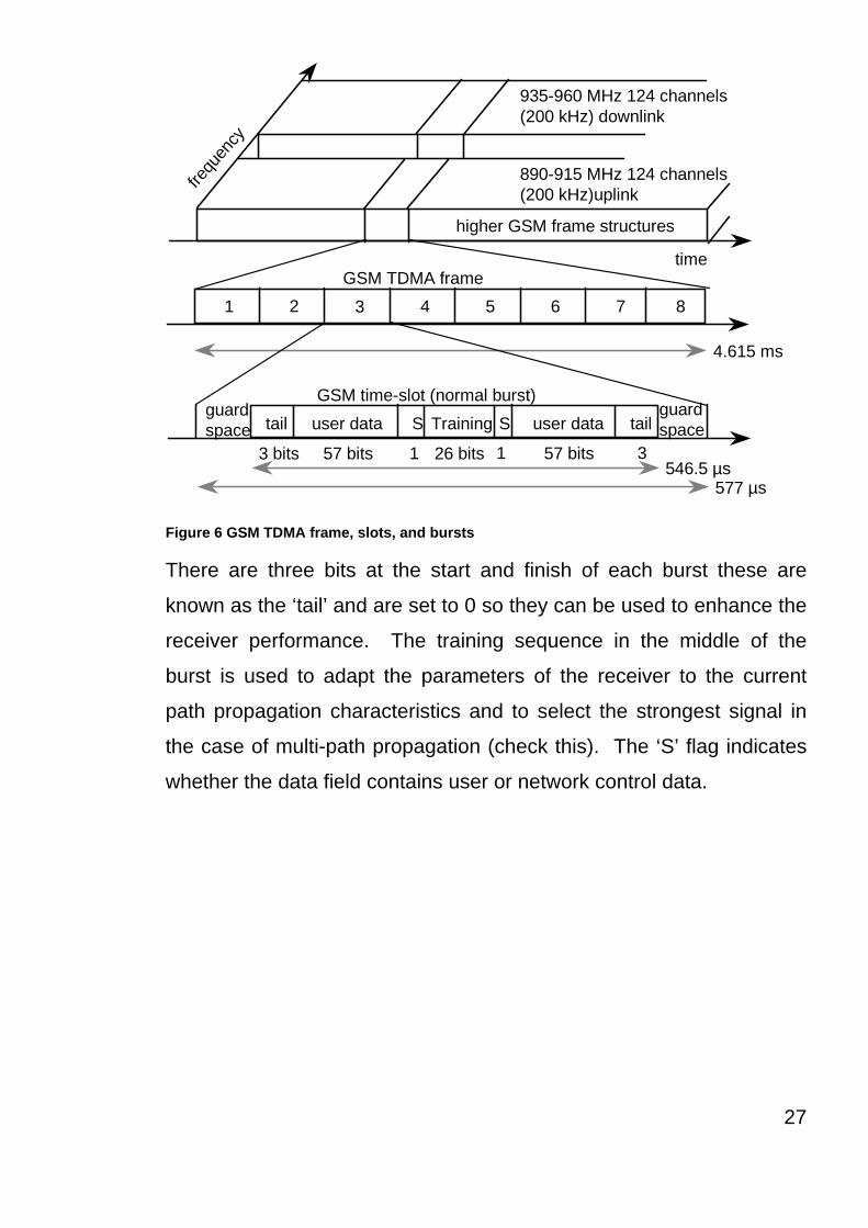
The duration of a frame is 4.615 ms which is subdivided into 8 GSM
time-slots, where each slot represents a TDM channel and lasts for
577 µs. Hence each TDM channel occupies the 200 kHz carrier for
577 µs every 4.615 ms.
Data is transmitted in small sections known as a ‘burst’ figure 6 shows
a normal burst as used for data transmission inside a time slot. In this
example (Figure 6) the burst is only 546.5 µs long and contains 148
bits of data. The remaining 30.5 µs is used as guard space which is
done to prevent overlapping with other bursts due to the different path
delays and to leave the transmitter time to turn on and off. However, if
the full slot if filled with data that would allow the transmission of 148
bits within the 546.5 µs. So each physical TDM channel has a data
rate of around 38.8 kbit/s, but each radio carrier transmits around 270
kbit/s over the Um interface.
26
1 2 3 4 5 6 7 8
higher GSM frame structures
935-960 MHz 124 channels(200 kHz) downlink
890-915 MHz 124 channels(200 kHz)uplinkfre
quen
cytime
GSM TDMA frame
GSM time-slot (normal burst)
4.615 ms
546.5 µs577 µs
tail user data TrainingSguardspace S user data tail
guardspace
3 bits 57 bits 26 bits 57 bits1 1 3
Figure 6 GSM TDMA frame, slots, and bursts
There are three bits at the start and finish of each burst these are
known as the ‘tail’ and are set to 0 so they can be used to enhance the
receiver performance. The training sequence in the middle of the
burst is used to adapt the parameters of the receiver to the current
path propagation characteristics and to select the strongest signal in
the case of multi-path propagation (check this). The ‘S’ flag indicates
whether the data field contains user or network control data.
27
Two factors allow for the use of simple transmitter hardware: on the
one hand, the slots for uplink and downlink of a physical TDM channel
are separated in frequency (45 MHz for GSM 900 and 95 MHz for
GSM 1800 using FDD). On the other hand, the TDMA frames are
shifted in time for three slots. i.e., if the BTS sends data at time t0 in
slot one on the downlink, the MS access slot one on the uplink at time
t0+3.577µs. An MS thus does not need a full-duplex transmitter, a
simpler half-duplex transmitter switching between receiving and
sending is enough. In order to avoid frequency selective fading, GSM
specifies an optional slow frequency hopping mechanism. MS and
BTS may change the carrier frequency after each frame, based on a
common hopping sequence. An MS changes its frequency between
up and downlink slots respectively.
28
2.1.3.1. Logical Channels and Frame Hierarchy
GSM specifies two basic groups of logical channel, they are the Traffic
Channels and the Control Channels :
Traffic Channels (TCH): The GSM network uses a TCH to transmit
user data (e.g. Voice). There are two basic TCHs and they are
defined as Full Rate TCH (TCH/F) and Half Rate TCH (TCH/H). A
TCH/F has a data rate of 28.8 kbit/s, whereas the data rate for TCH/H
is 14.4 kbit/s. At the beginning of GSM standardisation the voice
codecs only required 13 kbit/s, whereas the remaining capacity of
TCH/H was used for error correction (TCH/FS). However, newer
codecs allow for better voice coding and can make use of TCH/H.
Making use of these TCH/Hs doubles the capacity of the GSM system
for voice transmission, but reduces speech quality. For data
transmission there are many different traffic channels, for example
TCH/F4.8 for 4.8 kbit/s, TCH/F9.6 for 9.6 kbit/s, and in the newer
specifications TCH/F14.4 for 14.4 kbit/s. It should be noted that that
these logical channels differ in their coding and their level of error
correction. However data throughput is < 2Kb/s.
Control Channels (CCH): The GSM network makes use of many
different CCHs, for they control medium access, allocation of traffic
channels or the mobility management. Three main groups of CCHs
have been defined, each has their own sub-channels.
Broadcast Control Channel (BCCH): The BCCH is used by the BTS to
signal all MSs within a cell. The sort of information transmitted in this
channel is such as the cell identification, options available within this
29

cell (frequency hopping), and the available frequencies within the cell
and in neighbouring cells, known as the neighbour list. In addition to
this, the BTS sends information about frequency correction using the
FCCH (Frequency Correction Channel), and also information about the
time synchronisation via the SCH (Synchronisation Channel). Both of
these channels, the FCCH and the SCH are sub channels of the
BCCH.
Common Control Channel (CCCH): The CCCH is the channel where
all information about connection set up between the MS and the BS is
exchanged. For calls toward the MS, the BS uses the PCH (Paging
Channel). However if a MS wants to set up a call, it uses the RACH
(Random Access Channel) to send data to the BTS. The RACH
implements multiple access to all MSs within a cell, and all MSs may
access this channel. This however is where collisions may occur
between MSs in the GSM system, so the BTS uses the AGCH (Access
Grant Channel) to signal an MS that it can use the TCH or SDCCH for
further connection set up.
Dedicated Control Channel (DCCH) : The previous two channels
(BCCH and CCCH) are unidirectional, the DCCH and it’s sub channels
are bi-directional. As long as an MS has not established a TCH with
the BTS, it uses the SDCCH (Stand-alone Dedicated Control Channel)
with a low data rate (782 bit/s) for signaling. The signaling is generally
made up of authentication, registration and/or other data needed to set
up the TCH. Each TCH and SDCCH has a SACCH (Slow Associated
Dedicated Control Channel) associated with it. This channel is used to
exchange system information such as the Channel Quality and the
30

signal power level. Finally, if more signaling information needs to be
transmitted and a TCH is already existing, GSM uses a FACCH (Fast
Associated Dedicated Control Channel). The FACCH uses the time
slots which are otherwise used by the TCH and is necessary,
especially in the case of handovers where the BTS and the MS have
to exchange larger amounts of data, in a smaller amount of time,
known as layer 3 messages (not ISO/OSI reference model).
31

2.1.4 Protocols
Figure 7 shows the architecture of protocols used within the GSM
system, with signaling protocols, interfaces as well as the entities
already shown in Figure 5.
Again the main area of focus is in the Um interface, this is because the
other interfaces occur between entities in a fixed network. The
physical layer, Layer 1 handles all the radio specific functions. This
layer includes the creation of bursts according to the five different
formats, the multiplexing of bursts into TDMA frames, synchronisation
with the BTS, detection of the idle channels and the measurement of
the channel quality on the downlink. At Um, the physical layer uses
GSMK (Gaussian Shift Minimum Keying) for the digital modulation and
performs encryption/decryption of data This means that encryption is
not performed end-to-end, but only between MS and BTS over the air
interface.
32

CM
MM
RR
MM
LAPDm
radio
LAPDm
radio
LAPD
PCM
RR’ BTSM
CM
LAPD
PCM
RR’BTSM
16/64 kbit/s
Um Abis A
SS7
PCM
SS7
PCM
64 kbit/s /2.048 Mbit/s
MS BTS BSC MSC
BSSAP BSSAP
Figure 7 Protocol Architecture for signaling
The synchronisation also includes the correction of the individual path
delay between the MS and the BTS, all MSs within a cell can use the
same BTS and hence must be synchronised to the BTS. This is due
to the fact that the BTS generated the time-structure of the frames and
slots etc. This can be problematic since in this context there are
different RTTs (Round Trip Time). An MS that is close to the BTS has
a very short RTT whereas an MS that is 35 km away has a RTT of
around 0.23 ms.. If the MS 35 km away used the slot structure without
correction, a large guard spaces would be required as 0.23 ms. are
already 40% of the 0.577 ms available for each time slot. (Wray
Castle, GSM Appreciation, 1998.). Therefore the BTS sends the
current RTT to MS, which then adjusts its access time so that all
bursts reach the BTS within their limits. This mechanism ensures that
33
the guard space is reduced to only 30.5 µs or 5%. See Figure 7. This
means the adjustment of the access is controlled via the variable
timing advance, where a burst can be shifted up to 63 bit times earlier,
with the resulting bits having a duration of 3.69 µs, thus will result in
the 0.23 ms needed.
The physical layer has several main tasks that comprise the channel
coding, error detection/correction; this is directly combined with the
coding mechanisms. FEC (Forward Error Correction) is used
extensively in the coding channel, FEC adds redundancy to the user
data, thus allowing for the detection and correction of selected errors.
The power of the FEC scheme depends on the amount of redundancy,
coding algorithm, and any further interleaving of data to minimise the
effects of burst errors. Whatsmore the FEC is the reason that error
detection/correction occurs in the physical layer. This differs to the
ISO/OSI reference model where it occurs in layer two. The GSM
physical layer tries to correct errors, however it does not deliver
erroneous data to the higher layers.
GSM logical channels use different coding schemes with different
correction capabilities, for example speech channels need the
additional coding of voice data after analogue to digital conversion.
This is in order to reach a data rate of 22.8 kbit/s (using the 13 kbit/s
from the voice codec plus redundancy, CRC bits, and interleaving
(Goodman, 1997). When GSM was envisaged it was assumed that
voice would be the main service so the physical also contains special
functions, for instance VAD (Voice Activity Detection), which transmits
voice data only when there is a voice signal. In the duration between
34
voice activity, the physical layer generates a comfort noise to fake a
connection, however no actual transmission takes place.
All the interleaving in the voice channel is to minimise interference due
to burst errors and the recurrence pattern of a logical channel
generates a delay for transmission, although this delay is only about
60 ms for TCH/FS and about 100 ms for TCH/F9.6. These times have
to be added to the transmission delay if the BTS is communicating with
an MS rather than a standard fixed station (for example a stationary
computer etc.) and this in turn may influence the performance of any of
higher layer protocols, e.g.. for computer data transmission.
Signaling between the entities within the GSM network requires the
use of the higher layers (see Figure 7). For this, the LAPDm (Link
Access Procedure for the D-Channel) protocol has been defined at the
Um interface for layer two. As the name already implies, it has been
derived from link access procedure for the D-Channel (LAPD) in the
ISDN system, which is a version of HDLC (Goodman, 1997), LAPDm
is a lightweight version of LAPD, in that it does not require
synchronisation flags or check summing for error detection, these are
not needed as these functions are already performed in the physical
layer of the GSM network. LAPDm, however offers reliable data
transfer over connections, re-sequencing of data frames and flow
control (ETSI, 1993, ETS 300 937), (ETSI, 1999) TS 100 938. Due to
the fact that there is no buffering between layer one and two, the
LAPDm has to obey the frame structures, recurrence patterns etc
defined for the reassembly of data and
acknowledged/unacknowledged data transfer.
35

Layer three in the GSM network is made up of several sublayers as
shown in Figure 7, the lowest sublayer is the RR (Radio Resource
Management). Only part of this layer the RR’, is implemented in the
BTS, the remainder of the RR is situated in the BSC. The BSC via the
BTSM (Base Transceiver Station Management) are responsible for the
functions of the RR’. The RR’ has the function of setting up,
maintenance and release of the radio channels. Also the RR’ has
direct access to the physical layer for radio information and offers a
reliable connection to next higher layer.
MM (Mobility Management) encompasses the functions for
registration, authentication, identification, location updating and the
provision of TMSI (Temporary Mobile Subscriber Identity) that replaces
the IMSI (International Mobile Subscriber Identity) and is needed to
obscure the true identity of the MS over the radio air interface.
Although the IMSI identifies the user, the TMSI is only valid within the
location area of a VLR. MM also offers a reliable connection to the
next higher layer.
Finally the CM (call management) layer contains three entities : CC
(Call Control), SMS (Short Message Service) and SS (Supplementary
Services). SMS allows for short messages transfer using the control
channels SDCCH and SACCH, while SS offers the services described
in section 2.1.1.3. CC provides a point-to-point connection between
two terminals, the higher layers for call management use this, call
clearing and change of call parameters. This layer also contains
functions to send in-band tones, called DTMF (Dual Tone Multiple
Frequency), over the GSM network.
36
Additional protocols are used at the Abis and the A interfaces. Data
transmission at the physical layer is typically done using PCM (Pulse
Code Modulation) systems. Although PCM systems offer transparent
64 kbit/s channels, GSM allows for the sub-multiplexing of four 16
kbit/s channels into single 64 kbit/s (while remembering that 16kbit/s
are enough for user data from an MS). At the physical layer, the A
interface typically includes leased lines with a capacity of 2.048 Mbit/s.
LAPD is used for layer two at Abis, BTSM for the BTS management.
For signaling between the MSC and a BSC, the SS7 (Signaling
System No, 7) is used. This protocol also transfers all the
management information between MSC’s, HLR, VLR’s and OMC.
Additionally, and MSC can control a BSS via the BSSAP (Base Station
[Sub] System Application Part).
37

2.1.5 Localisation and Calling
One of the main features of GSM system is the automatic, worldwide
localisation of it’s users. The GSM system always knows where a user
is currently located, and the same phone number is valid worldwide.
To have this ability the GSM system performs periodic location
updates, even if the user does not use the MS, provided that the MS is
still logged on to the GSM network and is not completely switched off.
The HLR contains information about the current location, and the VLR
that is currently responsible for the MS informs the HLR about the
location of the MS when it changes. Changing VLRs with
uninterrupted availability of all services is also called roaming.
Roaming can take place within the context of one GSM service
provider or between two providers in one country, however this does
not normally happen but also between different service providers in
different countries, known as international roaming.
To locate an MS and to address the MS, several numbers are needed:
MSISDN (Mobile Station International ISDN Number)16. The only
important number for the user of GSM is the phone number, due to the
fact that the phone number is only associated with the SIM, rather than
a certain MS. The MSISDN follows the E.164, this standard is also
used in fixed ISDN networks.
IMSI (International Mobile Subscriber Identity). GSM uses the IMSI for
internal unique identification of a subscriber.
TMSI (Temporary Mobile Subscriber Identity). To disguise the IMSI
that would give the exact identity of the user which is signaling over
38

the radio air interface, GSM uses the 4 byte TMSI for local subscriber
identification. The TMSI is selected by the VLR and only has
temporary validity within the location area of the VLR. In addition to
that the VLR will change the TMSI periodically.
MSRN (Mobile Station [Subscriber] Roaming Number)17. This is
another temporary address that disguises the identity and location of
the subscriber. The VLR generates this address upon request from
the MSC and the address is also stored in the HLR. The MSRN is
comprised of the current VCC (Visitor Country Code), the VNDC
(Visitor National Destination Code) and the identification of the current
MSC together with the subscriber number, hence the MSRN is
essential to help the HLR to find a subscriber for an incoming call.
All the numbers described above are needed to find a user within the
GSM system, and to maintain the connection with a mobile station.
The following scenarios below shows a MTC (Mobile Terminate Call)
and a MOC (Mobile Originated Call).
39

Callingstation GMSC
HLR VLR
BSSBSSBSS
MSC
MS
1 2
3
4
5
6
7
8 9
10
11 12
13
1610 10
11 11 11
14 15
17
1: calling a GSM subscriber2: forwarding call to GMSC3: signal call setup to HLR4, 5: request MSRN from VLR6: forward responsible MSC to GMSC7: forward call to current MSC8, 9: get current status of MS10, 11: paging of MS12, 13: MS answers14, 15: security checks16, 17: set up connection
PSTN
Figure 8 Mobile Terminated Call
GMSC
VLR
BSS
MSC
MS1
2
6 5
3 4
9
10
7 8
1, 2: connection request3, 4: security check5-8: check resources (free circuit)9-10: set up call
PSTN
Figure 9 Mobile Originated Call
40

BTSMS
paging request
channel request
immediate assignment
paging response
authentication request
authentication response
ciphering command
ciphering complete
setup
call confirmed
assignment command
assignment complete
alerting
connect
connect acknowledge
data/speech exchange
BTSMS
channel request
immediate assignment
service request
authentication request
authentication response
ciphering command
ciphering complete
setup
call confirmed
assignment command
assignment complete
alerting
connect
connect acknowledge
data/speech exchange
MTC MOC
Figure 10 Message Flow for MTC and MOC
41

2.1.6 Handover
GSM systems require a procedure known as a Handover to maintain
the continuity of the call. This is because a single cell does not cover
the whole service area e.g. a whole city or country. However a single
cell has a maximum service area of approximately 23 miles (35 km) for
each antenna (Tripathi, et al. 1998). The smaller the size of the cell
and the faster the movement of the MS through the cells (Up to 155
mph (250 kph) for GSM), the more handovers of ongoing calls are
required, but a handover should not cause the a call drop. Basically
there are two main reasons for handovers, however the GSM
Specification identifies 40 reasons.
The MS moves out of coverage of the serving BTS thus the signal
level becomes lower continuously until it falls beneath the minimal
requirements for communications. Or the error rate may grow due to
interference, the distance to the BTS may be do high. All these effects
may diminish the quality of the radio link and make transmission
impossible in the near future.
The wired infrastructure i.e. the MSC, BSC may decide that the traffic
in one cell is too high thus introducing congestion and hence decides
to shift some MSs to other cells with a lower level of traffic, if that is
possible. Thus, handovers can be used as a method of controlling
traffic through load balancing to relieve localised congestion.
42

Figure 11 shows four possible handover scenarios with in the GSM
system.
MSC MSC
BSC BSCBSC
BTS BTS BTSBTS
MS MS MS MS
1
2 3 4
Figure 11 Types of handover within a GSM system
1. Intra Cell Handover : This happens when within a cell, when
narrowband interference could make transmission at a certain
frequency impossible. The BSC could then decide to change the
carrier frequency. (1)
2. Inter Cell, intra BSC handover : This type of handover is a typical
handover within the GSM system and occurs when the MS moves
from one BTS to another but stays within the control of same BSC.
The BSC performs the handover and assigns a new radio channel in
the new BTS, then releases the old BTS. (2)
3. Inter BSC, Intra MSC handover : Since a BSC controls a limited
number of BTSs, the GSM system has to perform handovers between
BSCs. This form of handover is controlled by the MSC. (3)
43
4. Inter MSC handover : A handover could also be required
between two BTSs that belong to two different MSCs, now both MSCs
perform the handover together. (4)
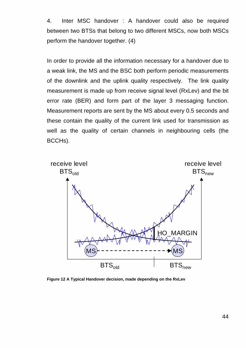
In order to provide all the information necessary for a handover due to
a weak link, the MS and the BSC both perform periodic measurements
of the downlink and the uplink quality respectively. The link quality
measurement is made up from receive signal level (RxLev) and the bit
error rate (BER) and form part of the layer 3 messaging function.
Measurement reports are sent by the MS about every 0.5 seconds and
these contain the quality of the current link used for transmission as
well as the quality of certain channels in neighbouring cells (the
BCCHs).
receive levelBTSold
receive levelBTSnew
MS MS
HO_MARGIN
BTSold BTSnew Figure 12 A Typical Handover decision, made depending on the RxLev
44

Figure 12 shows a handover decision, using the RxLev as the MS
moves away from the BTSold (BTSold is the serving cell) towards
another BTS (BTSnew). In the handover decision shown in figure 12,
the handover decision is made not purely on the instantanious value of
the receive signal level, but on the average value.
So what’s happening. The BTS collects all the values (RxLev and
BER from the uplink and downlink) from the BTS and MS, then
calculates the average values. These values are then compared to
the Handover Margin (HO Margin). The HO Margin includes a
hysteresis level to avoid the “ping-pong” effect (Wong, 1997). (Without
hysteresis, even short-term interference, e.g. shadowing due to a
building, could cause a handover). However, even with the HO Margin
some ping-pong can still occur. If the HO Margin is set to high then
this could cause dropped calls due to low RxLev, and if it is set to low
then there will be many handovers in a short period, hence the ping-
pong effect and a significant reduction in the quality of the service.
The HO Margin will change between rural and urban areas, but
typically will be set at –8db.
The following three figures shows the typical measurement reports,
and cell details for a handover. These measurements were taken
using TEMS Investigation 2.02, supplied by Ericcson.
Typical Measurement reports for a Handover
45

Figure 13 Measurement Reports Before Handover
(Source Ericsson Network Optimization Solutions, TEMS Investigation
2.02)
46

Figure 14 Handover Command
(Source Ericsson Network Optimization Solutions, TEMS Investigation
2.02)
47
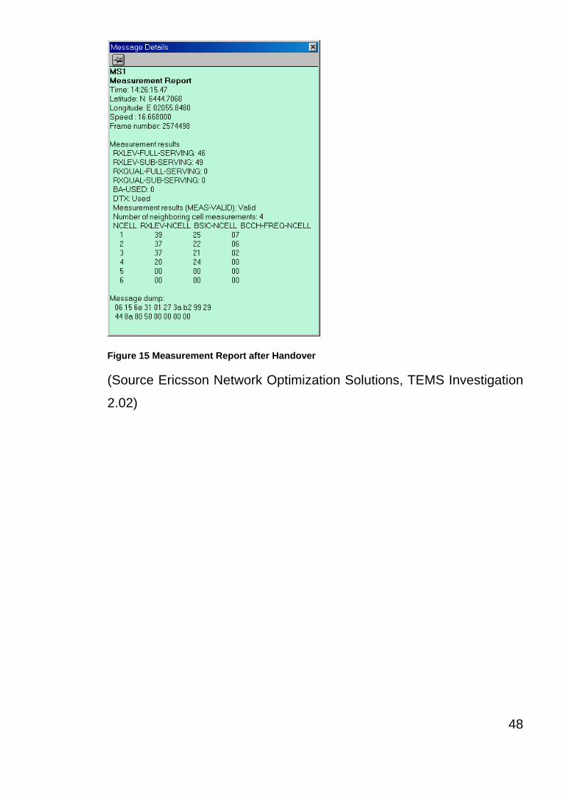
Figure 15 Measurement Report after Handover
(Source Ericsson Network Optimization Solutions, TEMS Investigation
2.02)
48

2.1.7 Security
The GSM system has several security services for security, these
security services use confidential information that is stored in the AuC
and in the customers SIM (Subscriber Identity Module) chip. The SIM
chip may be plugged into any MS, however for the SIM chip to allow
access to the MS the user must enter a PIN (Personal Identification
Number), the SIM chip contain personal, secret data. The following
are the security services offered by GSM:
Authentication and Access Control : For any MS to be used on the
GSM network a number of events have to take place, the first event
includes the authentication of a valid user for the SIM, the user enters
their secret PIN to access the SIM. Then the MS contacts the AuC
(See Figure 16 (Authentication Request)).
Confidentiality : All data that is related to the user is encrypted, after
authentication the BTS and MS apply encryption to data, voice and
signaling. This confidentiality only exist between the BTS and MS,
however it does not exist end-to-end or within the whole fixed
GSM/telephone network.
Anonymity : The GSM system also provides a level of anonymity, all of
the data is encrypted before transmission, and user identifiers that
would show the identity of a user are not used over the air. Instead
the GSM system uses a temporary identitfier (TMSI), this is newly
assigned by the VLR after each location update. Further more the
VLR can change the TMSI at any time.
The GSM system uses three different algorithms to provide security
services, the A3 algorithm is used primarily for authentication, A5 is
used for the encryption/decryption and A8 which is used for the
49

generation of a cipher key. Out of the three algorithms A5 was the
only one that was publicly available, where as A3 and A8 were secret,
but standard with open interfaces. However that change in 1998 when
A3 and A8 were published on the internet.
50

2.1.7.1 Authentication
As I have already stated before any user can access the GSM system
they must be authenticated as a valid user and this authentication is
done by use of the PIN on the SIM. The SIM stores the users
Individual Authentication Key Ki, the user identification IMSI and used
the A3 algorithm for identification.
The authentication method that is used is challenge – response : the
access control will generate a random number RAND as a challenge,
and the SIM within the MS has to answer with a signed responses
SRES as response. The AuC performs the basic generation of the
RAND, signed responses SRES, and cipher key Kc for each IMSI, then
forward this information to the HLR, then current VLR then requests
the suitable values for the RAND, SRES and the Kc from the HLR.
For authentication the VLR sends the random value RAND to the SIM.
Each side, the GSM network and the subscriber module, must perform
the same operation with the RAND and the Ki. The MS sends back
the SRES generated by the SIM, the VLR can now compare both
values. If the value produced by the SIM and the VLR match then the
user is granted to access the GSM network, however if they do not
match then the subscriber is refused access to the network. This
process is shown in Figure 16
51

A3
RANDKi
128 bit 128 bit
SRES* 32 bit
A3
RAND Ki
128 bit 128 bit
SRES 32 bit
SRES* =? SRES SRES
RAND
SRES32 bit
mobile network SIM
AC
MSC
SIM
Ki: individual subscriber authentication key SRES: signed response Figure 16 Subscriber Authentication
52
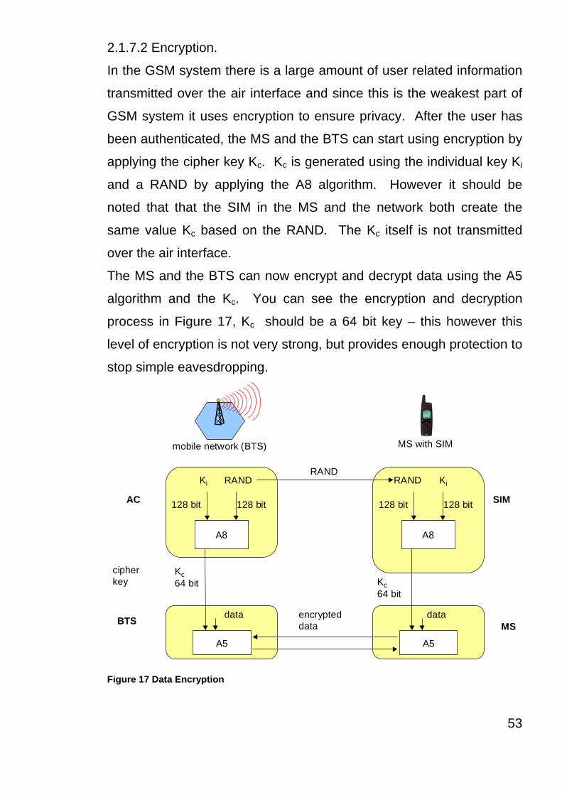
2.1.7.2 Encryption.
In the GSM system there is a large amount of user related information
transmitted over the air interface and since this is the weakest part of
GSM system it uses encryption to ensure privacy. After the user has
been authenticated, the MS and the BTS can start using encryption by
applying the cipher key Kc. Kc is generated using the individual key Ki
and a RAND by applying the A8 algorithm. However it should be
noted that that the SIM in the MS and the network both create the
same value Kc based on the RAND. The Kc itself is not transmitted
over the air interface.
The MS and the BTS can now encrypt and decrypt data using the A5
algorithm and the Kc. You can see the encryption and decryption
process in Figure 17, Kc should be a 64 bit key – this however this
level of encryption is not very strong, but provides enough protection to
stop simple eavesdropping.
A8
RANDKi
128 bit 128 bit
Kc64 bit
A8
RAND Ki
128 bit 128 bit
SRES
RAND
encrypteddata
mobile network (BTS) MS with SIM
AC
BTS
SIM
A5
Kc64 bit
A5
MSdata data
cipherkey
Figure 17 Data Encryption
53

Since the publication of the algorithm’s A3 and A8 on the Internet, it
has show that there are certain limitations for example 10 of the 64bits
are always set to 0, hence the real length of the key is only 54 bits.
The consequence of this is that the encryption is much weaker.
54

Chapter Summary and key Points
With the increase in demand for the need for communications whist away from a
fixed line, GSM specifications were developed in order to provide greater capacity,
improved quality and significantly greater security. Also the need to be able to use
your mobile phone in other countries became of paramount importance.
GSM provided significantly greater capacity by the use of a
combination of FDMA and TDMA. Whereas in previous technologies
such as TACS and MTN the modulation technique was analogue and
thus not very secure, GSM utilizes digital encoded modulation (See
section 2.1.7.2), thus making it virtually impossible for interception by
the casual eaves dropper. As a result of this certain Government
agencies found it impossible to intercept calls and decode them in real
time (DEA, See Appendix 2). However, in recent years details of the
encryption algorithms have been made available to these agencies,
and then leaked on the internet, thus reducing the security of the GSM
system.
A further security improvement brought about by GSM was the use of
SIM cards. The SIM card holds data relating to the user,
authentication codes, and billing details.
The GSM radio air interface (Abis) is split into two levels, Physical
Channels which are the radio bearers and Logical Channels which
contain all the control and speech information in data streams. These
logical channels are described in GSM Section 2.1.3.1. The net
55

outcome is that speech only occupies a small amount of these data
streams, hence the use of TDMA on the FDMA radio bearers.
56
Mobility means that the MS is moving from one location to another.
Thus the system has to know where the MS is in order to direct calls.
The MS continually provides a location update so that the network
knows where to find the MS. Also because the MS is moving the
network has to handover from BSC to another BSC, or another sector
in the BSC. Consequently the MS has to continually measure the
signal levels and quality in order to know which BSC has the
appropriate availability in terms of capacity and quality. In this way the
network is able to maintain connectivity and quality of service to the
user.
With this increased mobility, users started to demand the ability to
send data from their PCs and thus the mobile internet was born. In
earlier technologies data transmission was achieved by the use of an
analogue modems, but with GSM digital modems are now
incorporated into the some MSs, thus providing greater data
throughput.
The success of GSM data transmissions has meant that users require
faster and faster speeds. On fixed lines the technique known as
packet switched data transmission was available, but this was no use
for GSM as the human ear cannot tolerate the delays introduced by
such a technology. Initially data on the GSM network used a
technique known as circuit switched (GSM-CS), which meant that the
MS was permanently connected to a specific circuit, which was
necessary for speech transmission. In order to increase the data rate
a new technology based around packet switching had to be developed
and thus the evolution of the GSM network continues into EDGE.
57

58

Chapter 3 : EDGE (Enhanced Data rates for GSM Evolution)
59

3.1 The Evolution of the GSM Network
The existing mobile digital communications network continues to
develop, in order to increase capacity, coverage, quality and data
transmission rates. There have been a series of developments that
are now starting to be deployed with the aim of enhancing the GSM
network functionality.
Figure 3.1 shows the enhancements planned for the next few years,
starting off with High Speed Circuit Switched Data (HSCD). The next
development is General Packet Radio Services (GPRS), this is a
packet-switched service that allows full mobility and wide-area
coverage. Enhanced Data rates for GSM Evolution (EDGE) will use
enhanced modulation and related techniques, further improving local
mobility. Universal Mobile Telecommunications System (UMTS) will
include second and third generation services.
GSM CS data servicesupto 9.6 kbit/s
GSM HSCSD services upto 38.4 kbit/s(later upto 64 kbit/s
GSM GPRS services upto160kbit/s
UMTS
EDGE
1991/1992 1998 1999/2000 2002
Functionality
Time
Figure 18 Evolution of GSM Data Service
60
(Adapted from Ericsson Document EN/LZT 123 5374 R1B)
61

3.2 High Speed Circuit Switched Data (HSCSD)
HSCSD is basically an upgrade of the original GSM CS data
transmission system, by using HSCSD the speed at which data is
transmitted is greatly improved. The higher data transmission rates
are achieved by making use of bundled Traffic Channels (TCH). The
way that this works is the MS requests one or more TCHs from the
GSM network, in other words the MSC will allocate TDMA slots within
a TDMA frame. This allocations do not need to be asymmetrical i.e.
more slots can allocated downlink than the uplink, this fit the behavior
of most users, typically the user will download more than they will
upload. HSCSD requires software upgrades in an MS and MSC, this
is because both have to be able to split a single traffic stream into
several traffic streams, each using a TCH, and then to combine the
streams again.
In theory a single MS could use all eight time slots within a TDMA frame to
achieve an Air Interface User Rate (AIUR), for example 8 TCH/F14.4 channels or
115.2 kbit/s (ETSI 1998) TR 101 186. One major problem with this configuration is
that the MS is required to send and receive at the same time. However standard
GSM does not support this, uplinks and down links are always shifted for three
slots. ESTI, (1997) EN 301 344, specifies that the AIUR available at 57.6 kbit/s
(duplex) using four time slots and four time slots for the downlink, the table on the
next page shows the allowable combinations of TCHs and allocated slots for non-
transparent services.
62

AIUR TCH/F4.8 TCH/9.6 TCH/14.4
4.8 kbit/s 1 - -
9.6 kbit/s 2 1 -
14.4 kbit/s 3 - 1
19.2 kbit/s 4 2 -
28.8 kbit/s - 3 2
38.4 kbit/s - 4 -
43.2 kbit/s - - 3
57.6 kbit/s - - 4
Table 4.1(Available Data Rates for HSCSD)
(Adapted from Ericsson Document EN/LZT 123 5374 R1B)
Although HSCSD delivers major advantages in data transmission over
GSM CS it does have several major disadvantages, it still uses a
connection-orientated mechanisms of GSM, these mechanisms are
not very efficient when it comes to computer data traffic, which
typically uses bursts of data. If a large file is being downloaded
HSCSD may require all channels to be reserved, where as typical web
browsing would leave the channels idle most of the time. The
allocation of channels is reflected directly in the service cost, as once
the channels have been reserved by one HSCSD user other users can
not use them, even if they are idle.
HSCSD was not used by any of the UK operators, this was because of
the disadvantages stated above and the fact that GPRS came along
so fast.
63
Tele
met
ry
Not
ifica
tion
Poin
t of S
ale WWW Access
File TransferVideo
Bur
stin
ess
Bandwidth(bps)
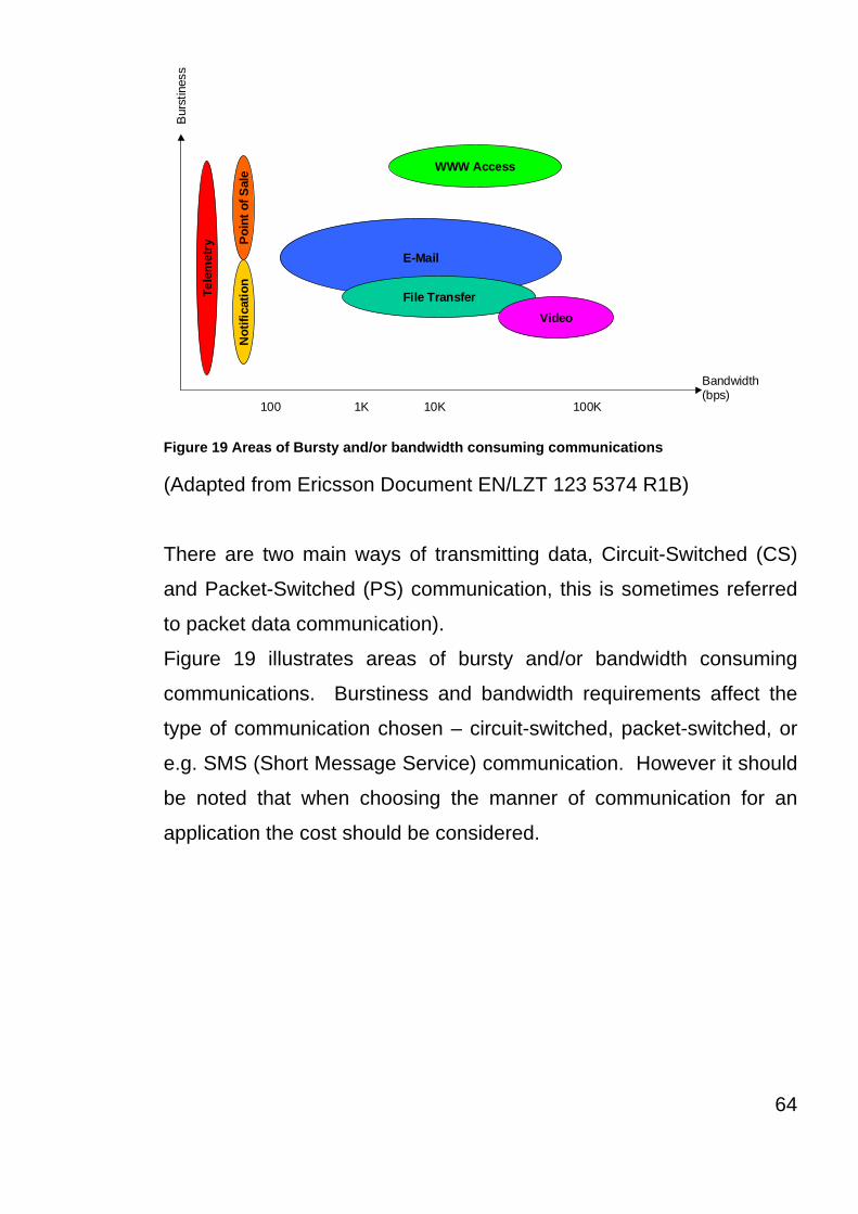
100 1K 10K 100K Figure 19 Areas of Bursty and/or bandwidth consuming communications
(Adapted from Ericsson Document EN/LZT 123 5374 R1B)
There are two main ways of transmitting data, Circuit-Switched (CS)
and Packet-Switched (PS) communication, this is sometimes referred
to packet data communication).
Figure 19 illustrates areas of bursty and/or bandwidth consuming
communications. Burstiness and bandwidth requirements affect the
type of communication chosen – circuit-switched, packet-switched, or
e.g. SMS (Short Message Service) communication. However it should
be noted that when choosing the manner of communication for an
application the cost should be considered.
64

3.3 General Packet Radio Service (GPRS)
3.3.1 System Overview
The parts of the GPRS system that carry out the switch of packet data
are called the Serving GPRS Support Node (SGSN) and the Gateway
GPRS Node (GGSN). The SGSN provides a packet routing to and
from the geographical SGSN service area. The GGSN makes up the
interface towards the external IP packet networks, the SGSN.GGSN is
physically separated from the circuit-switched part of the GSM system.
The other parts of the GPRS architecture utilize the current GSM
network elements.
BTS
BSC
GMSCMSC/VLR
SGSN
EIR
HLR
ISDN/PSTN
Internet
AUC
OtherPLMN
GGSNCorporateLAN
ExternalX.25Network
IP-BackboneNetwork
{{TE MT
MS
AbisA
Gb
Gs
Gn
Gp
Gf
Gr
Gi
TE
MT
MS
BSS
BTS
BSC
GMSC
MSC
VLR
HLR
AUC
EIR
SGSN
GGSN
Um
A, Abis
Gx
Terminal Equipment
Mobile Terminal
Mobile Station
Base Station System
Base Transceiver System
Base Station Controller
Gateway Mobile Services Switching Center
Mobile Switching Center
Visitor Location Register
Home Location Register
Authentication Center
Equipment Identity Register
Serving GPRS Support Node
Gateway GPRS Support Node
Air Interface
Interfaces (GSM)
Interfaces (GPRS)
Traffic and signaling
Signaling
Figure 20 GPRS Logical Architecture
(Adapted from ETIS 1998 EN 301 344)
65

Terminal Equipment (TE) The TE is the computer terminal that the end user uses. This is the
component used for the GPRS system to transmit and receive end
user packet data. For example, the TE could be a laptop computer.
The GPRS system provides for IP connectivity between the TE and an
Internet Service Provider (ISP), or a Corporate Local Area Network
(LAN) connected to the GPRS system. From the users point of view
the MT could be compared to a conventional modem.
Mobile Terminal (MT) The MT communicates with a TE, and over the air with the BTS, the
MT must be equipped with software for GPRS functionality when used
in conjunction with the GPRS system. The MT is associated with a
subscriber in the GSM system, the MT established SGSN. Channel
reselection is provided at the radio link between the MT and the
SGSN, the IP connection is static from the TE point of view, that is, the
TE does not know it is mobile and retains its assigned IP address until
the MT detached.
Base Station System (BSS) The BSS consists of a Base Station Controller (BSC) and a Base
Transceiver Station (BTS). The BTS is the radio equipment, that
transmits and receives information over the air to let the BSC
communicate with MSs in the BSCs service area. A group of BTSs is
controlled by the BSC, however for GPRS to work on the BTS it must
have the GPRS specific software.
66
The BSC provides all the radio related functions. The BSC can set up,
supervise and disconnect circuit switched and packet switched calls, it
has a high capacity switch, this provides function such as handover
decisions, cell configuration data and channel assignment. The BSC
must also be equipped with both the GPRS hardware and software
when used for GPRS, one or several BSCs are served by an MSC,
and a number of BSCs are served by an SGSN.
The BTS separates the MS originated circuit switched calls from the
packet switched data communications, before the BSC forwards a
circuit switched calls to the MSC/VLR, and packet switched data to the
SGSN.
The standard GSM protocols are used with the BSC to achieve the
desired compatibility.
Mobile Services Switching Center (MSC) The MSC performs the telephony switching functions of the GSM
circuit switched system, like the SGSN switches the GSM packet
switched traffic, it controls calls to and from other telephony and data
systems, such as the PSTN, ISDN, PLMN, Public Data Networks and
possibility some private networks.
The SGSN Routing Area (RA) The SGSN Routing Area (RA) is a subset of the MSC (CS) Location
Area (LA). An MSC Location Area is a group of BSS cells, the system
uses the Las to search for subscribers in the active state. An LA is the
part of the network in which an MS may move around with out
reporting its location to the network.
67

One MSC/VLR Service Area (SA) is made up of a number of LAs, the
SA is the part of the network that is covered by one MSC. However
there can be more than one MSC corresponding to one SGSN, one
MSC can also be connected to several SGSNs.
Gateway Mobile Services Switching Center (GMSC) The GMSC switches the circuit switched calls between GSM circuit
switched network and the PSTN which is the fixed telephony network,
hence it serves the function of routing incoming calls to the MSC
where the mobile subscriber is currently registered, it is normally
integrated in the same node as the MSC/VLR. The GMSC does not
need any upgrading for GPRS.
68

The Home Location Register (HLR) As stated in the section about the GSM Network the HLR is the
database that holds all the subscription information for every person
who has bought a from the GSM operator. The HLR stores
information for the CS and PS communication, information stored the
HLR includes, for example supplementary services, authentication
parameters, Access Point Name (APN) such as subscribers ISP, and
whether a static IP address is allocated to the MS. In addition, the
HLR also includes information about the location of the MS. The main
difference between this and the GSM system is that the information
from the HLR is exchanged between the HLR and the SGSN.
The information that is exchanged between the HLR and the SGSN
has been set up by the operator for the user, this information transfer
is done when the operator changes the subscriber information, or
when a new SGSN needs to have data for a subscriber after the MS
has connected or in roaming, the old SGSN is also informed if the MS
is roaming. The information that is going from the HLR to the SGSN is
basically the routing information that is transferred upon an MS action,
e.g. attach or roaming. For a roaming MS, the HLR may be in a
different PLMN that the SGSN that is serving the MS.
Visitor Location Register (VLR) The VLR database contains all the information about all MSs that are
currently located in the MSC LA or the SGSN routing area
respectively. The SGSN actually contains the VLR functionality for
packet-switched communications, similarly, the circuit-switched VLR is
an integrated component of the MSC. Another function of the VLR is
69
that it contains the temporary subscriber information needed by the
MSC or SGSN to provide services for visiting subscribers.
For MSs that support GPRS (PS) and GSM (CS), both the SGSN and
the MSC will obtain location information from the HLR when the MS is
combined-attached, i.e. both GPRS- and IMSI/CS-attached.
The GPRS VLR consists of software in a serving GRPS Support Node,
the VLR contains information about the SGSN that is used.
The MSC/VLR is connected to the SGSN directly using the Gs
interface, and indirectly via the BBS using the A and the Gb interfaces.
Serving GPRS Support Node (SGSN) For the upgrading of the GSM network to cope with GPRS the SGSN
is the primary component, and the SGSN is a new component in GSM.
The SGSN forwards all incoming and outgoing IP packets addressed
to/from an MS that is attached within the SGSN service area. The
SGSN provides packet routing and transfer to and from the SGSN
service area. SGSN serves all GPRS subscribers that are physically
located within the geographical SGSN service area. A GPRS
subscriber may be served by any SGSN in the network, all depending
on the geographical location. The traffic is routed from the SGSN to
the BSC, via the BTS to the MS. Also the SGSN provides:
Ciphering and Authentication
Session Management
Mobility Management
Logical Link Management toward the MS
Connecting to HLR, MSC, BSC, GGSN and other nodes
Output of billing data
70

Gateway GPRS Support Node (GGSN) As with the SGSN the GGSN is a new primary component in the GSM
network when using GPRS. The GGSN provides the following
functions:
The interface toward the external IP packet networks, the GGSN
therefore contains access functionality that interfaces with an external
ISP, functions such as, routers and RADIUS (Remote Dial-In User
Services) servers. From and external IP networks point of view the
GGSN is acting as a router for the IP addresses of all subscribers
served by the GPRS network. So the GGSN exchanges routing
information with the external network.
GPRS session management, communication setup toward external
network.
Functionality for associating the subscribers with the right SGSN.
Output billing data, the GGSN collects information for each MS, related
to the external data network usage. Both the GGSN and the SGSN
collect billing information on the usage of the GPRS network
resources.
Equipment Identity Register (EIR) See GSM section 2.1.2.3 (Page 25)
Authentication Center (AUC) The AUC is a GSM component that provide triplets to the
authentication and ciphering process used within GSM, the
authentication for GPRS is the same as for GSM users, the only
change is in the security for GPRS is related to ciphering, however this
change does not require any change in software or hardware.
71

72
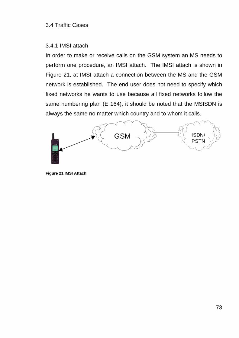
3.4 Traffic Cases
3.4.1 IMSI attach
In order to make or receive calls on the GSM system an MS needs to
perform one procedure, an IMSI attach. The IMSI attach is shown in
Figure 21, at IMSI attach a connection between the MS and the GSM
network is established. The end user does not need to specify which
fixed networks he wants to use because all fixed networks follow the
same numbering plan (E 164), it should be noted that the MSISDN is
always the same no matter which country and to whom it calls.
GSM ISDN/PSTN
Figure 21 IMSI Attach
73

3.4.2 GPRS Attach
In order for the GPRS MS to receive or transmit data the end user
needs to perform a two-step procedure, GPRS attach (Figure 21) ND
PDP context activation (Figure 22)
GPRS
LAN 1
LAN2
1
2 Figure 22 GPRS attach (1) and PDP context activation (2)
At GPRS attach a logical link is established between MS and SGSN,
the GPRS attachment procedure in Figure 23.
BSC SGSN
MSC/VLR
SGSN
HLR
AUC1, 3, 4, 7
2
6
4, 5
Figure 23 GPRS Attach
MS sends message to SGSN: “attach request”.
If the MS is not known by the SGSN it asks the old SGSN about the
IMSI and triplets.
If the MS is not known by the old SGSN it sends an error message to
the new SGSN and the new SGSN asks MS about IMSI.
74

SGSN authenticates MS.
Update HLR (if new SGSN service area).
Update MSC/VLR (only necessary if new LA).
SGSN tell the MS about new TLLI (Temporary Location Link ID).
3.4.3 Combined GPRS/IMSI Attach
In a combined GPRS/IMSI attach, both of the previous procedures are
carried out simultaneously, shown in Figure 24.
LAN 1
LAN2
GSM
GPRS
PSTN/
ISDN
Figure 24 Combined GPRS/IMSI attach
75

3.4.4 PDP Context Activation and Deactivation
In order for the MS to send and receive GPRS data the MS must
perform a PDP context activation after the GPRS attach (Shown in
Figure 23). The PDP context activation makes the MS known in the
concerned GGSN and communication to external networks is made
possible.
The PDP context activation corresponds from the end users
perspective to “Logging On” to an external network.
The difference from using a dial-up connection over circuit switched is
that in GPRS the end user can have several PDP contexts activated
simultaneously if the terminal supports several IP addresses.
3.5 GPRS Air Interface
The air interface (Um) is the logical link between the MS and the BSS.
Figure 25 shows the GPRS Protocol Stack from the perspective of the
BSS
GSM RF
MAC
RLC
LLC
SNDCP
IP / X.25
Application
L1
L2
IP
UDP/TCP
GTP
IP / X.25
GSM RF L1bis L1bis L1
L2
IP
UDP/TCP
GTP
NetworkService
BSSGP
LLC
SNDCPRelay
NetworkServiceMAC
RLC BSSGPRelay
MS BSS SGSN GGSNUm Gb Gn Gi
Figure 25 GPRS Protocol Stack
(Thomas, R, et al, 1999, France Telecom)
The Layers are described in Appendix 1.
76

3.6 Logical Channels
Within GPRS there are a number of new logical channels, similar to
the existing ones, but these are only for GPRS. (NB These logical
channels have been standardized.) The new logical channels have
been mapped onto the physical channels that have been assigned for
packet data, the physical channels denoted as Packet Data Channels
(PDCH), the logical channels that are mapped onto these are :
Packet Common Control Channels
PRACH : Packet Random Access Channel (Uplink)
PPCH : Packet Paging Channel (Downlink)
PAGCH : Packet Access Grant Channel (Downlink)
PTCCH : Packet Timing advance Control Channel (Up/downlink)
PNCH : Packet Notification Channel (Downlink)
Broadcast Channel
PBCCH : Packet Broadcast Control Channel (Downlink)
Packet Traffic Channels
PDTCH : Packet Data Traffic Channel (Up/downlink)
PACCH : Packet Associated Control Channel (Up/downlink)
77

3.7 PDCH Allocation
The following section will explain how the PDCH is allocated. Traffic
Channels and packet data channels basically create a common pool of
resources, utilizing the existing resources in an efficient way. See
Figure 26
1 2 3 4 5 6 7 8
BTS BSC
TS
BCCH
CarrierFrequencies
PDCH carrying PCCCH
PDCH not carrying PCCCH
CCCH, TCH or free time slot
PDCH TCH
Common Resource Pool
Figure 26 Common Recourse Pool
The PDCHs are allocated to the PCU, the PCU is responsible for
assigning channels to different GPRS MSs. The PDCHs can be
allocated in different ways:
Dedicated PDCHs are allocated and released by operator command.
On-demand PDCHs, serving as temporary dynamic GPRS recourses,
are allocated and released depending on GPRS traffic demand.
The channels that are allocated for GPRS (PDCH) are allocated in
sets of maximum four consecutive time slots, such a set is called a
PEST (Shown in Figure 27), a PEST can consist of both dedicated and
on demand PDCH. All PESTS are on the same frequency or hop the
78

same frequency hopping set. An MS can only be assigned PDCHs
from one PEST, at present this limits the maximum number of
assigned time slots to four, there is no additional limit on the number of
PDCHs that can be allocated in a cell, except the number of available
TCHs.
MS4
MS2
MS1
MS3
MS2
MS1
MS3
MS2
MS1
MS5
MS3
MS1
MS5
MS6 MS6 MS6
TBF TBF
PDCHs PDCHs
TBFlimit
To GPRSidle list
PEST1 PEST2
Figure 27 Channel Reservation (PESTs)
3.7.1 Dedicated PDCH
Dedicated PDCHs can only be used for GPRS, the operator can
specify between zero and eight dedicated PDCHs per cell, the reason
for dedicated PDCHs is to ensure that there is always the GPRS
resources in a cell. To some extent the operators can specify to where
they dedicated PDCH(s) to be located. However from a radio point of
view, non hopping channels on the BCCH carrier are generally not
equivalent to traffic channels on other frequencies. The operator can
decide if the PDCH shall be allocated on the non-hopping BCCH
frequency as primary or secondary choice, or with no preference.
79
3.7.2 On-demand PDCH
On-demand PDCH can be pre-empted by incoming circuit switched
calls in congested cells, it should be noted that in a HSCSD, a user
can never get more than a single channel through the pre-emption
procedure.
There is no physical limit on how many on-demand PDCHs there can
be in a cell. However the number of on-demand PDCHs depends on
how much packet switched traffic there is, upto the limit where circuit
switched traffic starts
3.7.3 Master PDCH
A master PDCH (MPDCH), is a PDCH carrying a PBCCH and
PCCCH, as well as GPRS traffic. The PCCCH carries all the
necessary control signaling to initiate packet traffic. In the standard,
the MPDCH is called “the PDCH carrying the PBCCH”. NB the
abbreviation MPDCH is only used within Ericsson systems.
The first directed PDCH that is allocated according to the operator’s
preferences regarding non-hopping BCCH will be configured as an
MPDCH. The following PDCHs that are allocated will only carry GPRS
traffic and associated signaling. However in a cell with no MPDCH
(i.e. no dedicated PDCH allocated) the ordinary control channels such
as the BCCH, RACH etc, will handle the broadcasting and signaling to
the GPRS mobiles.
3.8 Cell Selection and Reselection
Comparing GPRS with circuit switched
In a GSM network the BSC governs the cell selection behavior of the
MS when in idle and active mode by different methods. Idle mode
80

MSs autonomously performs cell reselection by using the C1/C2
criteria.
In active mode, non-GPRS MSs are steered by the locating
functionality implemented in the BSC. So this means that the BSC
initiates the handovers to other cells. With GPRS, the MS determines
the base station with which it will communicate, Figure 28 shows the
handover procedures for both Circuit Switched and Packet Switched.
The GPRS MS manages both the idle packet and transfer packet
mode behaviors.
BSC
Circuit Switched Packet Switched
•MS Measures on neighboring cells.
•MS Decides which cell to use.
•Locating algorithm is in MS. Locating parameter is broadcasting by thenetwork.
•MS sends measurement reports ~2/sec
•BSC decides when a handover should occur. Figure 28 Handover, comparison between CS and PS
The cell selection and reselection algorithm used for controlling the
idle/transfer mode behaviors are governed by the GPRS cell selection
and reselection parameter setting broadcast in the packet system
information on the PBCCH in each GPRS capable cell with an
allocated PBCCH (MPDCH). If no PBCCH has been allocated in a
81

cell, the GPRS MS will read the system information broadcast on
BCCH and use the C1/C2 criteria for cell selection and reselection as
in the circuit switched idle mode case.
So as you can see the GPRS cell selection and reselection algorithms
are governed by parameter settings. These parameters C31 and C32
are different to the corresponding parameters for the circuit switched
system. However with some GPRS systems GPRS cell section
parameters are automatically mapped on those for cell
selection/locating known from the circuit switched case. The reason
for this is to achieve the same cell selection behavior for GPRS, as
with GSM, this will enable an easy rollout of GPRS in the network.
The GPRS standard allow the network to take over cell reselection for
a specific MS or for all MSs. This is called Network Controlled Cell
Reselection and have not yet been implemented in any UK or
European GPRS systems.
82

3.8.1 GPRS Support Node (GSN)
The GSN is a general purpose, high-performance packet switching
platform, the GSN combines features usually more associated with
data communications (features such as compactness and high
functionality) with features from telecommunications such as
robustness and scalability. The GSN is designed for non-stop
operation, the platform incorporates 1+n redundant hardware, and also
the software is of a modular design enabling individual modules to be
upgraded with out causing any interference to the traffic.
3.9 Interconnection Principles.
In this section the connection between GSNs and their operating
environment, the interfaces used in the GPRSN network and the
GSNs, and their contexts are shown in Figure 29, the interface names
are part of the ETSI GSM standard for GPRS.
TE MT BSS SGSN GGSN
MSC/VLR HLR
PDN TE
SM-SCSMS-GMSCSMS-IWMSC
SGSN
Other PLMN
GGSN
R Um Gb Gn Gi
Gd
Gn Gp
EIR
Gf
A
D
E C
Gr
Gs
Signaling InterfaceSignaling & DataTransfer Interface
Figure 29 GPRS Logical Architecture
(Adapted from ESTI 301 344 V6.3.2 (1999))
83

3.10 GPRS IP Connectivity
One of the main advantages of GPRS is that it provides IP
connectivity, this means that communication between the different
parts of the operators GPRS system, the GGSN, administrative hosts
and hosts providing Internet Services. Further more the IP
connectivity enables easy communication with the Internet. However
is should be noted that GPRS has two different types of
communications, represented with two different levels of IP
communication:
The IP communications within the GPRS network. This is for
signaling, management etc.
3.11 The users IP communication.
The latter is the communication between a GPRS MS and an ISP, for
example. The GPRS system provides IP connectivity between MS
and ISPs, using the GSM standard, data transfer is based on the
common internet protocol (IP), which means that packet data
transmission is carried out on an end-to-end basis (including the air
interface). From the users point of view a modem connection to the
internet is provided when using an GPRS MS.
An interface that communicates using the IP protocol must have an IP
address and identifier, now since the GPRS system uses the IP
protocol for both the end-user traffic and the system user traffic, both
MSs and system components need IP addresses.
The IP addresses used in the GPRS system, for system and for end-
user communication, can be public, dynamic or static.
84

Chapter Summary and Key Points
In GSM Circuit switched data, the typical maximum data rate of data
throughput was officially 9.6 kbit/s, however when the overhead of
control, guard data, encryption keys and error correction, are taken
into account the typically user data throughput was only 1 – 1.5 kbit/s.
The first phase of the GSM evolution to higher speed data was the
introduction of High Speed Circuit Switched Data (HSCSD). This gave
the user the potential of data rates up to 38.4 kbit/s, which after the
overhead was accounted for allowed a user data rate of 14 kbit/s. This
improvement in data throughput was achieved by the use of multiple
time slots, but was at the expense of the main revenue earning service
(speech).
Due to the fact that data is tolerant to delays in transmission, as
opposed to speech a new technique utilizing packet switching was
developed (GPRS)
GPRS differs significantly from HSCSD in that it is not permanently
connected to a single physical channel. Like HSCSD, GPRS utilizes
multiple time slots, but the network has the ability to reduce the
number of time slots used so that speech traffic is given priority. The
disadvantage to the data user is that during peak hour traffic data
throughput will be significantly reduced by the network in order to
accommodate the higher revenue potential of speech traffic.
85
To the network operator the introduction of GPRS has meant a
significant modification of the existing GSM network infrastructure.
The advantage to the network operator is that they can now use a
packet switched network for data transmission instead of dedicated
circuit switched network. This has major economic advantages for the
network operator. During speech transmissions, there are many
instances of no information being transmitted but with data,
transmission is continuous. It is for this reason that data does not
need to be permanently connected as the data can always be re-
arranged at the terminal end.
With users requiring faster and faster data speeds and even the ability
to download multimedia applications, a new technology had to be
developed due to the fact that GSM had reached it’s maximum data
throughput. Also the network had to consider whether it was
connected to a data or speech call. So the next step in the evolution
was the development of Wideband CDMA, leading to UMTS.
86

Chapter 4 : WCDMA (Wideband CDMA)
87

4.1 WCDMA
WCDMA of 3G potentially will offer the user significantly increased
data throughput rates. Speeds of up to 2mbit/s and higher are being
predicted but it will be sometime before these are achieved. New
techniques such as voice over IP are being developed for use on the
Transport Infrastructure and will bring significant advantages to the
operator especially in terms of data compression techniques used in
such transmission modes as ATM. Increased data throughput means
greater capacity for a given amount of frequency spectrum and thus
lower costs for both Infrastructure and spectrum licences. Potentially
the benefits of WCDMA to the user and operator are massive with
greater data rates for the user and reduced costs for the operator.
88

4.2 Carrier Spacing and Deployment Scenarios
The carrier spacing has a range of 200 kHz and can differ from 4.2 to
5.4 MHz, the different carrier spacing can be used to obtain suitable
adjacent channel protections depending on the interference scenario.
Figure 30 shows an example, where the bandwidth of 15 MHz with
three cell layers. Larger carrier spacing can be applied between
operators, than within one operators band in order to avoid inter-
operator interference. Interfrequency measurements and handovers
are supported by WCDMA to make use of three cell layers and
carriers. Power
Frequency
4.2 - 5.0 MHz 4.2 - 5.0 MHz
5.0 - 5.4 MHz 5.0 - 5.4 MHz
3 Cell Layers
Operator Band 15Mhz
Another WCDMAOperator
Another WCDMAOperator
Figure 30 Frequency utilization with WCDMA
(Adapted from Holma, H. et al 2000)
89

4.3 Logical Channels
WCDMA mainly follows the ITU Recommendation M.1035 in the
definitions of logical channels. The following logical channels are
defined for WCDMA.
4.4 Control Channels
BCCH : Broadcast Control Channel carries system and cell specific
channels;
PCH : Paging Channel for messages to the mobiles in the paging
area;
FACH : Forward Access Channel for messages from the base station
to the mobile in one cell.
In addition to the two Control Channels there are also two Dedicated
Channels;
DCCH : Dedicated Control Channel, this covers two channels : stand-
alone dedicated control channel (SDCCH), and the Associated Control
Channel (ACCH);
DTCH : Dedicated Traffic Channel for point to point data transmission
in the uplink and downlink.
90

4.5 Uplink Physical Channels
There are two dedicated channels and one common channel for the
uplink. User data is transmitted on one of these channels, the
Dedicated Physical Data Channel (DPDCH), as is the control
information. The Random Access Channel is a common access
channel.
The Dedicated Physical Control Channel (DPCCH) is needed to
transmit pilot symbols for coherent reception, power signaling bits, and
rate information for rate detection. The two basic solutions for
multiplexing physical control and data channels are time multiplexing
and code multiplexing. A combined IQ and code multiplexing solution
(dual-channel QPSK) is used in the WCDMA uplink and to avoid
Electromagnetic Compatibility (EMC) problems with Discontinuous
Transmission (DTX).
There is a major drawback of a time multiplexed control channel, that
is where there are EMC problems that arise when DTX is used for data
transmission. Figure 31 shows an example of DTX during normal
speech transmission. During periods when there is silence there is no
need for information bits to be transmitted. This results in pulsed
transmission of the of the control data that has to be transmitted.
DPCCH : Pilot +power control Absent Data DPPCH + Data
Data Present Data PresentData Absent
Figure 31 Pulsed Transmission when time multiplexed control channel
(Adapted from Holma, H. et al 2000)
91

The Random Access Burst is made up of two parts; a preamble which
is made up of 16c256 chip (1ms) and a data part but data parts length
is not a fixed length and this is what gives WCDMA its variable data
rates. The random access system is based on slotted ALOHA
technique; Figure 32 shows the structure of the random access burst.
Before the transmission happens the Mobile Station (MS) has to carry
out a number of tasks:
Achieve chip, slot, and frame synchronization to target BSS from the
SCH;
Retrieve information from the BCCH about the random access code
used in the target cell/sector;
Estimate the downlink path loss, which is used together with a signal
strength target to calculate the required transmit power of the random
access request.
MS ID Reg. Service CRC
16 X 256 chips Variable length
User Packet
Data Part
Preamble Part Figure 32 The structure of a Random Access Burst in a WCDMA System
92

4.6 Downlink Physical Channels
There are three physical channels in the downlink; the primary and
secondary Common Control Physical Channels (CCPCH) carry the
downlink for the common control logical channels (BCCH, PCH and
FACH); the SCH provides timing information and in WCDMA is used
for handover measurements by the Mobile Station (MS).
The dedicated channels (DPDCH and DPCCH) are multiplexed,
however this means that there is an EMC problem caused by
discontinuous transmission, but this is not considered a significant
problem to the downlink, for two reasons :
There are signals to several users transmitted in parallel and at the
same time.
Base Stations are not so close to other electrical equipment.
4.7 Packet Data
There are two very different types of packet data transmission within
the WCDMA system. Short data packets can be added to the random
access bursts and this method is called Common Channel Packet
Transmission (CCPT). CCPT is most commonly used for short
infrequent packets, where link maintenance needed for a dedicated
channel would lead to an unacceptable overhead. Another factor for
the use of CCPT cuts out the delay that can be associated with a
dedicated channel. It should also be noted that for common channel
packet transmission only open loop power control is in operation
(Open Loop Power control measures the interference conditions from
the channel, and adjusts the transmission power adoringly to meet the
desired frame error rate (Ojanpera, T etal. 1998)). CCPT should
93
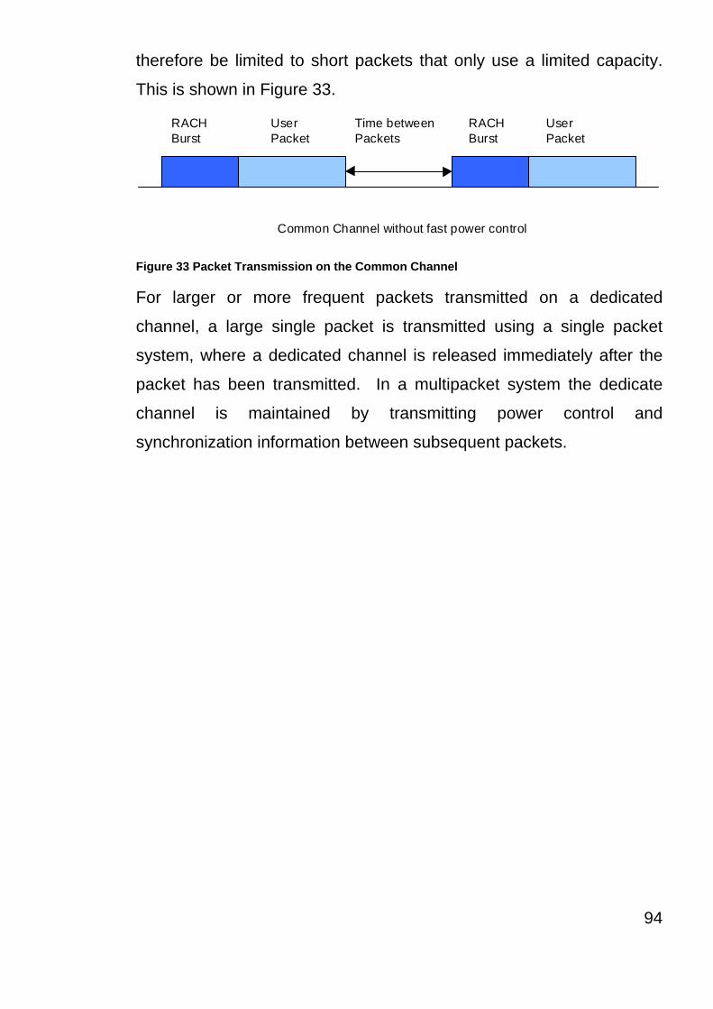
therefore be limited to short packets that only use a limited capacity.
This is shown in Figure 33.
RACHBurst
RACHBurst
UserPacket
UserPacket
Time betweenPackets
Common Channel without fast power control Figure 33 Packet Transmission on the Common Channel
For larger or more frequent packets transmitted on a dedicated
channel, a large single packet is transmitted using a single packet
system, where a dedicated channel is released immediately after the
packet has been transmitted. In a multipacket system the dedicate
channel is maintained by transmitting power control and
synchronization information between subsequent packets.
94

4.8 Handovers
The WCDMA system’s base stations do not need to be synchronized,
and hence, there is no need for an external source of synchronization
such as GPS. Asynchronous base stations have to be considered,
especially when designing soft handover algorithms and when
implementing position location services.
Before a soft handover happens, the MS measures observed timing
differences of the downlink SCHs from the two base stations. The
timing of a new downlink soft handover connection is adjusted with a
resolution of one symbol. For example, dedicated downlink signals
from the two base stations that are synchronized with an accuracy of
one symbol. This enables the mobile RAKE receiver to collect the
micro diversity energy from the two base stations. From this the timing
adjustments of dedicated downlink channels can be carried out with a
resolution of one symbol without losing orthogonality of downlink
codes.
4.8.1 Soft Handovers
Soft handovers with WCDMA are very different to the handovers used
in the GSM system and this basic principle stems from the US system
CDMA. Basically the MS is connected to more than one BTS (Base
Station Transceiver) at a time. The reason for this is to reduce
interference into other cells (BTSs). It also has the advantage of
improving performance through macro diversity.
Figure 34 illustrates a soft handover principle. The uplink signal fro the
MS is received by both BTSs, which, after demodulation and
combining, pass the signal forward to the combining point, typically
this is the BSC. From a downlink point of view the same information is
95

transmitted via both BTSs, and the MS receives the information from
both of the BTSs as a separate multipath signals and can therefore
combine them.
BTS
BSC
BTS
Figure 34 Principle of soft handover with two base station transceivers (BTS)
Infrequent handovers are needed for utilizations of a hierarchical call
structures; macro, micro and indoor cells. Several carriers and inter-
frequency handovers may also be used for taking care of high capacity
needs in hot spots. Infrequent Handovers will be needed also for
handovers to the 2G systems (See UMTS). There are two methods
that are being considered for WCDMA, (1) Dual Receiver and, (2)
Slotted Mode.
96

Chapter Summary and Key points
GPRS saw the realization of the maximum data rate that can be
attained using the GSM system. So there was a need for Wideband
CDMA (WCDMA), this is an enhanced version of the mobile
communication system that is used in the United States. The main
use for WCDMA in the UK will be for mobile data communications, this
is because the UK already has an effective voice system in the GSM
system.
It should be noted that WCDMA has several major drawbacks, the
biggest being that with WCDMA used a form of DTX, this DTX causes
EMC (Electromagnetic Compatibility) problems. The DTX is used in
both Voice and Data transmission, but the problem only occurs when
the MS is in Data transmission mode.
WCDMA is not envisaged to by applied in the UK for the next 3-4
years, this will probably be around the same time that UMTS is made
available, however the potential benefits of WCDMA to the user and
operator are massive with greater data rates for the user and reduced
costs for the operator.
WCDMA is an integral part of UMTS (Universal Mobile
Telecommunications System). UMTS is an integration of
communications systems, and will hopefully provide a solid base for
mobile communications in the future.
97

Chapter 5 : UMTS (Universal Mobile Telecommunication System)
98

This page is intentionally left blank
99

5.1 UMTS Introduction
This chapter provides an overview of the GSM/UMTS core network, as
specified by the 3GPP release 99 standards. There is still no strict
formal definition of the core network, but the position of the core
network for the purpose of this chapter and how it relates to other parts
of the PLMN (Public Land Mobile Network) and co-operating networks.
Originally decided by the ETSI SMG, the 3GPP release 99, the UMTS
core network standard is evolved from the earlier GSM standards
releases. The core network forms the central part of a PLMN and
accommodates important functions for intra and inter PLMN roaming,
the provision of IP-connectivity and internet access, ISDN services and
interworking with other networks.
The core network may be looked upon as consisting of two different
parts :
Managing Circuit Switched mode communication services. (ISDN type
services)
Managing Packet Switched mode communication services. (GPRS
type services)
Although logically very different the two parts share certain core
network functionality, such as the HLR, Auc, EIR etc, and may also run
over a common transport infrastructure.
100

5.2 Horizontal Layering
Today’s modern telecommunications and data communications
environment consists of a variety of networks. Most of these networks
are highly specialized and optimized to serve a specific purpose such
as PLMN, ISDN/PSDT and Data/IP Network. To a larger extent these
networks are all vertically integrated in a sense they combine
functionality in one and the same network element.
Due to the fact that most networks are vertical in structure, they have
evolved separately and therefore differ in many respects. However,
this has the effect of limiting the network operators ability to create
synergies among their networks.
BSC
RNC
SCP SCS AS
Service Network Application Layer
EIRHLR
AUC
MSCServer
SGSNServers
GMSCServer
Core NetworkControl Layer
MGW MGWGGSN
IP/ATM
IP/ATM IP/ATM
PSTN
ISDN
Internet
Intranet
Core NetworkConnectivity Layer
Figure 35 Three Layered UMTS Core Network Architecture
(Adapted Edlin, B 2001)
101

The architecture of the core network for UMTS is shown is Figure 35,
this illustrates the way to evolve this multi-network situation in order to
overcome some of the existing defects. In short the UMTS solution is
based on a horizontalisation of the core network into a number of
independent networks. Basically UMTS is a “Network of Networks”
(Personal Comment). Special Media Gateways (MGW), controlled by
specific network servers, adapt and connect different access types to a
common backbone network. End user applications are provided by a
specific service layer, common to different access types.
5.3 General Principles
The layered core network architecture is derived from the current
standards reference model by separating the control plane functions,
thus turning these nodes into Servers and Media Gateways.
5.3.1 User Plane
The user plane, sometimes referred to as the connectivity layer (see
Figure 35), could be seen as a layer of distributed resources managing
user data (and signaling) flows. The user plane’s functions are
primarily handled by the GGSNs and the MGWs, located at the edges
of the core network. The MGW carries out the processing of end user
data such as speech coding and also acts as an access switch/router
to the backbone network. The MGW also sets up the bearer
connections carrying the user data flows in the user plane.
The MGWs are controlled by the MSC and SGSN servers via the
H.248 gateway control protocol. The resources needed for a
102

call/session may be distributed over multiple MGWs. For Circuit mode
communications the user data processing is primarily allocated to the
MGW on the boarder of the ISDN/PSTN.
For interconnecting the network elements in the user plane, different
transport technologies may be used.
103

5.3.2 Control Plane
The control plane houses a number of network servers and databases
of different types (MSC Server, SGSN Server, HLR, Auc, EIR etc).
These servers are responsible for handling subscriber data, security,
mobility management, setup and release of calls and sessions,
requested by the end users, circuit mode supplementary services and
similar functions. The network servers communicate among
themselves and with other network elements by means of standard
layer 3 protocols such as the following, Iu “Mobility Management”, Iu
“Call/Session control”, ISUP, MAP etc. The MSC and the SGSN
servers can also determine which MGW functions and resources are
required by the call/session and control these functions and resources
in the MGW by means of the H.248 gateway protocol.
5.3.3 Application Layer
The application layer is a simplified abstraction of the layer where most
of the end-user applications reside. To a large extent these
applications are implemented partly in the terminals and partly in the
specific application servers, which reside within the network*.
Applications exist in a broad variety, from the simple end-to-end client
server solutions to complex applications involving multiple interactive
end-systems, networks, media communication models etc.
* Some services handled by the network elements in the control plane,
particularly the more traditional supplementary services for circuit
mode communication.
5.4 Core Network Standards and Interfaces
(This section refers to the Ericsson UMTS Core Model)
104

The Ericsson core network architecture fully aligns with the 3GPP
release 99 standards and complies with the interfaces worked out by
the 3GPP. The separation of the control and user plane functions can
be seen as an enhancement to the release 99 reference model and
aligns with a number of important standardization initiatives in IETF,
ETSI, IT-U and other different industry forums.
As a result of the various control plane/user plane separation initiatives
in different standardization forums, a gateway control protocol (H.248)
has now been standardized by ITU-T.
105

5.5 Key Benefits of the Layered Architecture
The key principle of modern networking is the separation of network
functionality into independent layers; this is also true in the tele and
datacoms industry. The ‘layered’ thinking is also a very fundamental
and visible aspect in a number of standardization initiatives and
industry forums, such as Multiservice Switching Forum, led by several
of the largest operators and manufactures.
3G mobile communication systems are designed with these principles
in mind, and hence offer a number of advantages and possibilities.
Special attention needs to be put on meeting the requirements for
time-to-market, low cost of ownership, openness and future evolution
towards an “all-IP” solution.
Key characteristics :
Offers an open and versatile architecture capable of meeting the
current and future demand in a fast changing telecommunications
enviroment.
Provides and inherent flexibility for coping with growth and/or changing
traffic patterns and traffic mixes.
Independence between layers allows each layer to evolve
independently.
Provides great transport flexibility and allows different transport
technologies, both existing and new. To be deployed without
impacting the control or services/application layers.
Allows common transport arrangements for multi-services network.
Allows access independent and seamless services through a common
service/applications layer.
106
Provides efficient use of network resources.
Relies on proven and stable protocols and design.
Allow a very flexible re-use of investments in the GSM infrastructure.
107

5.6 Core UMTS Network Elements
The following section sets out the elements of the GSM/UMTS core
network, and some of the reasoning behind it. Figure 36 shows how
these core elements fit together and how they fit into the overall
system picture. However Figure 36 is not a true physical
representation of the core network, nor does it show all the interfaces.
As the core network has not been standardized there still exist other
possibilities for bundling different functions into physical network
elements.
IP-infrastructureRAN MGW
SGSN MSC GMSC
MGWGGSN
EIR HLR
AUC FNR
SCP
Service NW
BGw
CNN
Administration and BillingNetwork Management
PSTN
ISDN
Internet
Intranet
Core Network
PLMN - Domain
Figure 36 UMTS Core Network Elements
(Adapted from Ericsson Document EN/LZT 123 5374 R1B)
108

MSC Server
The MSC Server handles control layer functions related to circuit mode
communication services at the UTRAN and PSTN/ISDN borders and
performs among others the following functions:
- Media gateway control
- ISDN services control
- Mobility management
- Authentication
- Charging data collection/output
- Services switching function (5SF)
- Internet dial-in services (RAS)
- Element management
In addition to these functions the MSC Server also houses the
interworking and gateway functionality necessary to act as an SMS-
IWMSC and SMS-GMSC for the Short Message Service.
Serving GPRS Support Node Server (SGSN Server)
The SGSN Server handles control layer functions related to packet
mode communication services at the border between UTRAN and the
basic core network and performs among others the following functions:
- Media gateway control
- Session management
- Mobility management
- Authentication
- Charging control
- Relaying of SMS
- Element management
109

110
Media Gateway (MGW)
The MGW handles transport and user plane functions for both packet
and circuit mode communication at the borders between
networks/network segments. These lower layer functions primarily
concern the user data handling and includes e.g.:
- Media processing (speech coding. conference call bridging etc)
- Media generation (tones etc)
- Setup/release of user data bearers
- Provision of traffic/charging info for packet mode communication
- Security management
- Routing and switching QoS management
- Element management
Most MGW resources are shared between packet and circuit
communication services or can easily be re-configured from one
communication mode to the other. This offers a very cost efficient and
flexible solution for managing future changes in the circuit and packet
mode traffic balance.
Gateway GPRS Support Node (GGSN)
The GGSN constitutes the tunnel end-point for the GPRS specific
GTP-tunnel for packet mode communication and is situated on the
border between the basic UMTS core network and the ISP-POP”. The
GGSN is (indirectly) selected by the end-user at setup of the PDP-
context. From an addressing point of view the GGSN represents the
point of presence for ‘logged on’ end-users, i.e. end-users with an
established PDP-context. Addresses can be dynamically assigned
(fetched from an external server or a pool of own addresses) or
111

statically assigned (fetched from the HLR). In order to fulfill its role in
the network the GGSN performs the following functions among others:
- Tunnel management
- IP-address management
- Charging data collection/output
- Security management
- Packet filtering
- Packet routing/tunneling
- QoS management
- Element management
Optionally, a GGSN may also include certain non-GPRS specific
functions such as a Foreign Agent (FA).
Home Location Register (HLR)
The Home Location Register is a network database for mobile
telecommunications. The HLR holds all mobile specific subscriber
data and contains a number of functions for managing these data,
controlling services and enabling subscribers to access and receive
their services when roaming within and outside their home PLMN. The
HLR communicates with the GSNs, MSCs and other network element
via the MAP-protocol.
The Authentication Centre (AUC) contains functions for secure storage
of individual subscriber identifiers and keys. AUC also includes
algorithms necessary for generating authentication and ciphering data
based on the subscriber keys. The authentication and ciphering data,
provided by the AUC upon request, are used by different network
112

elements to protect the network, users and operators against
unauthorized use of the system.
113

Service Control Point (SCP)
The SCP is a part of the IN concept and contains the service logic and
its execution environment. The SCP works in close co-operation with
the service switching functions in the MSCs and provides IN-services
such as Virtual Private Network (VPN), Number Portability etc.
Flexible Number Register (FNR)
The FNR accommodates translation functions necessary to de-couple
end-user identities from the actual network databases holding end-
user data. These translation functions are essential in order to be able
to e.g.:
Easily reconfigure some of the network databases, e.g. as a result of a
growing number of end-users.
Allow end-users to keep their identities when changing from one
administration to another.
Equipment Identity Register (EIR)
The Equipment Identity Register is a network database holding status
information on mobile station equipment. The EIR is interrogated by
means of the MAP-protocol from e.g. network elements providing
access into the PLMN (MSC and SGSN servers), in order to ensure
that the mobile station equipment is not black-listed for any reason.
114
Cost Control Node (CCN)
The Cost Control Node is a central part of the 3G charging
environment. CCN contains centralized rating functions and
constitutes the charging determination point for services provided to
subscribers at both into and inter PLMN roaming. CCN also handles
credit limits for accumulated subscriber charges. These on-line
charging mechanism are used for provision of features such as credit
control (e.g. pre-paid), user cost information (advice of charge), fraud
control etc.
CCN receives traffic information on-line and off-line from the different
traffic handling/service nodes and instructs these nodes to proceed
with the calls/services according to the outcome of the operator
defined cost control analyses. CCN also has the ability to receive
CDR’s deriving from the Serving network providing near-real-time
revenue charging.
Billing Gateway (BGw)
The Billing Gateway is a key component for the off-line (CDR based)
charging in
UMTS. The BGw collects information from the different traffic
handling/service nodes (GSN, MSC. SMS-C. voice mail, application
servers. etc) and forwards it to the operator’s administrative systems
for off-line billing, accounting. traffic analyses and similar functions.
The BGw also acts as an intermediate storage and pre-processor for
formatting the CDR-information into the specific formats used by the
operator.
115

The BGw also provides an interface to CCN and can be used to relay
information for online charging from the traffic handling/service nodes
not having direct interfaces to CCN.
BGw also acts as an accounting/settlement broker by providing the
ability to distribute CDR’s from the Serving network to the Home
environment BGw or CCN in near real time.
5.8 Routers/Switches
For routing and switching of user data and signalling flows in the core
network connectivity layer, standard switches and routers are used.
Most infrastructures offer a wide range of routers and switches with
different functions and performance characteristics for most transport
needs in all segments of the network (access, aggregation, core) when
undertaking total or turnkey contracts.
116

5.9 Traffic Handling in a Layered Architecture
In order to facilitate the understanding of call/session handling in a
Server/Media Gateway architecture, with separated control and user
plane functions there are four traffic cases in the following sections.
Please note that these traffic cases have been simplified.
5.9.1 Traffic Cases
5.9.1.1 Mobile Originated Call An AAL2-switche core network has been assumed.
BS
MSCServer
TransitServer
MediaGateway
AAL2SWITCHRNC
Control Plane
RANAP
1,3,5
6,9
2,7
4
8,10
H.248
H.248
N-ISUP
9
PSTN/ISDNPLMNAAL2/ATM
backbone network
UTRAN
N-ISUP
Figure 37 Mobile Originated Call (Traffic Case)
1 A request for call setup is received from the UE. Selection of an
applicable MGW
2 Resources controlled by the MSC-server are reserved in the
selected MGW
3 The MSC-server orders the RNC to setup a radio access bearer
4 The User plane is setup from the RNC to the MGW
5 The MSC server is informed that the user plane setup to the
117

MGW has been completed
6 The call setup to the transit server is initiated by the MSC
7 Backward through connection of the equipment controlled by the
MSC server is ordered in the MGW
8 Resources controlled by the transit server are requested from the
MGW
9 Call setup to the selected PSTN switch is initiated by the transit
server
10 Through connection of the transit server controlled path in the
MGW is ordered
5.9.1.2 Mobile Terminated Call A simplified procedure for a mobile terminated call
BS
MSCServer
TransitServer
MediaGateway
AAL2SWITCHRNC
Control Plane
RANAP
H.248
H.248
N-ISUP
PSTN/ISDNPLMNAAL2/ATM
backbone network
UTRAN
N-ISUP
HLR MAPMAP
9
7,12,146,8,10,11,13
1
3,5
2b 2a
4
Figure 38 Mobile Terminated Call (Traffic Case)
1 An incoming call is received in the GMSC server
2 Routing data is obtained from the MSC server (VLR) via the
HLR
3 Resources controlled by the GMSC server are reserved in the
118

MGW
4 The call setup towards the visited MSC server is initiated by the
GMSC server
5 Through connection of the MGW resources is ordered by the
GSMC server
6 Paging of the called party is ordered by the MSC server, the call
setup is confirmed by the UE.
7 Resources controlled by the MSC server are reserved in the
MGW
8 The MSC server orders the RNC to setup a radio access bearer
9 The user plane is setup from the RNC to the MGW
10 The RNC informs the MSC server that the user pane setup to
the MGW has been completed
11 The MSC server is informed by the UE that altering of the called
party has started
12 The MSC server orders the MGW to start sending ringing tone
towards the calling party
13 Answer is received from the called party
14 Through connection of the MGW is ordered by the MSC server
119

5.9.1.3 PDP-context Activation
BS
SGSNServer
GGSNMediaGatewayRNC
Control Plane
InternetISP-POP
UTRAN
AAAServer
+
++IP network
HLR6
4 (H.248)
1,8
2,3
5, 7 (GTP)
UE
Figure 39 PDP-context Activation (Traffic Case)
1 An “active PDP context request” is sent by the UE to the SGSN
server
2 The SGSN server requests the UTRAN to setup a radio access
bearer (RAB)
3 The request for a RAB is acknowledged by UTRAN
4 The SGSN server requests the MGW to create a GTP tunnel
transfer point
5 A “create PDP context request” is sent from the SGSN server to
the GGSN
6 The GGSN server requests an IP address fro the AAA server (or
similar)
7 GGSN sends a “create PDP context response” back to the SGSN
server
8 An “active PDP context response” is sent back to the UE from the
SGSN server
120

5.9.1.4 Packet Forwarding
BS
SGSNServer
MediaGateway
Control Plane
InternetISP-POP
UTRAN
+
++RNC GGSN
HLR
UE
1
2 4
3
3 3
IP network
Figure 40Packet Forwarding (Traffic Case)
1 A PDU is sent from the UE
2 The PDU is forwarded over the GTP-U tunnel between the RNC
and the MGW
3 The PDU is forwarded over the core network GTP-U tunnel to the
GGSN
4 The PDU is forwarded to the Internet/ISP-POP
121

Chapter Summary and Key points
As technology stands at this time UMTS is the best solution for
modern mobile communications. This chapter on UMTS is mainly
based on the Ericsson view of what UMTS will be, this is down to the
fact that there have been no standards agreed.
One of the main advantages of UMTS is that it has a layered
architecture, this is different to other existing systems for mobile
communications which are vertical is structure.
The great advantage of UMTS is that it uses the existing systems for
mobile communication, UMTS is not necessarily a speaking a new
technology, but rather the application of existing technology.
Eventually the UMTS system will be able to detect what service the
user requires be it Voice or Data communication.
The mobile phone industry is already starting to work on new phones
which combine the functionality of a personal computer and the size of
a mobile phone.
122
Chapter 6 : The Future of Mobile Communications (10 years +)
123

6.1 The Future
UMTS is seen by most operators as the panacea for a total and
seamless cellular system. MSs will not only have to be tri or even
quad band but also multi mode (GSM & WCDMA) thus the complexity
will staggering. Initially, the user will probably have to select which
type of service they require (Speech or Data) but ultimately this service
detection will be done by the network. MSs will become smaller but as
the size of the human finger will not alter so there is a limitation in this
parameter. Voice control will be the order of day and the user may
only have one button to press, the on/off button. Eventually this may
even disappear as this function could be achieved simply tapping the
MS as is portrayed in the Sci Fi series Star Trek.
What is going to happen to the network is anybody’s guess. Already,
there as plans for the use of WANs in buildings where this acts as yet
another layer below the pico cell. This is already being trialed as an
extension to WCDMA.
Speech, will still for the foreseeable future be the main revenue earner
for the operator and combining this with video is likely to be the next
major advance. Perhaps, the speech will be handled on GSM and the
video on WCDMA but this will pose some interesting problems on
timing and synchronization. At the moment, everyone is concentrating
on getting UMTS right and compatible between countries and
manufacturers.
124

Chapter 7 Final Thoughts
125

7.1 Final Thoughts
Since the introduction of Cellular Mobile Communications in late 80s
early 90s, the number of users and the amount of traffic have
multiplied beyond all belief. To keep pace with the increase, both the
Telcoms Manufacturers and the operators have had to invest
enormous amounts of effort and money in developing and installing
new systems and technologies.
Initially, speech was the only service provided but with the advent of
the Laptop PC and the massive increase in the use of email, data
transmission started to become a significant proportion of the traffic.
The need for the mobile Internet is now the main driver for the
introduction of new services and consequently the development of new
technologies.
So what does this all mean to the User, the Operator and the
Manufacturer. In the following paragraphs, I will look into just some of
the important aspects of each of these categories.
7.2 The User:
Users have become use to relatively fast connections to the Internet
and Intranet using fixed lines from the office or their homes. Business
people on the move want to be able to connect to their company email
system from remote locations such as airport lounges and usually do
not have a lot of time in which to do it thus speed is of the essence.
126

GSM offered a solution but only at an effective data throughput of
about 1.5 kbit/s. Using such programmes as Microsoft Outlook, this
meant that you could spend up to half an hour downloading your
emails and this quite often was insufficient and did not allow any time
to actually send any emails, just collect incoming mails.
Edge was the next evolution to be developed and that is projected to
give the user a download throughput of up to 160 kbit/s. However,
once take off the transmission system overhead and the error
correction function, the effective rate reduced significantly but ended
up at about the same as you could expect from a 56 kbit/s modem on
a fixed network. For most business people this would show an
enormous improvement but was still not considered fast enough.
GSM/EDGE had reached it’s limit as far as speed for data
transmission was concerned and thus the development of WCDMA or
3G
WCDMA or 3G as it is commonly known, is projected to offer the user
data speed up to 2 mbit/s but those speeds are still sometime away.
Will this be enough for the user, I doubt it. However, it will be cost that
determines how fast the user will be able to go and what service
packages are offered for with operators changing the charging
principles from time to data throughput it could become extremely
expensive for the ordinary, non business user who will be the
numerical majority.
127

7.3 The Operator:
Users will want faster and faster data speed and more specialist services. The
Manufacturer wanting to sell new technology and having to recover all their
development costs in as short a time as possible to satisfy their shareholders.
Finally the Government charging exorbitant amounts of money for new licences
and the use different parts of the radio spectrum.
The recent sales of 3G licences in the UK gave the Governments something in
excess of £6B which the operators have to pay in advance. On top of that, they
will have to install a totally new infrastructure which means not only new Hardware
& Software but also the acquisition of new cell site locations, for WDCMA will
require more not less sites in order to offer good coverage at high speed. For
many years to come, the existing GSM service and infrastructure will provide the
main revenue for operators and this why they need to go for UMTS. This will allow
the operator to determine what service the user needs, speech, text messaging,
low, medium or high speed data transmission and then allocate the user to the
appropriate technology for the service they require (GSM/EDGE/WDCMA).
7.4 The Manufacturer:
The cost of developing new technologies is enormous, both in cash
and time. Once developed they have to be tested so not only does the
manufacturer have to develop the infrastructure but also the MS. The
MS market is extremely competitive so the potential for profits from
this market are not going to be as great as one would expect so the to
cross subsidisation of profits will be less.
128

Another problem faced by most of the major Manufacturers is that
when they try to sell their systems to operators, they find that they
have to finance the deal as well. This is because the operators are
cash limited due to the large amounts of money spent on acquiring the
new licences and spectrum. Some operators have negotiated deals
where the manufacturers will only start to get paid once the new
service starts to make a profit and that could be many years. The high
cost of licences and frequency spectrum is being sited as one of the
major causes in the current downturn in the Hi Tech shares.
7.5 The Winner:
So who is the real winner. I would say the Governments for they are in
a win, win situation. They made money on the licences, they make
money of the operators profits and they make money by fining
operators who do not provide the contracted quality of service required
by the Regulator. (Personal Comment)
129

List of Figures
Figure 1 GSM Evolutionary Concepts .................................................. 9
Figure 2 Uplink and Downlink frequencies for original GSM Spectrum
..................................................................................................... 12
Figure 3 Bearer and tele services reference model............................ 13
Figure 4 Functional Architecture of a GSM system ............................ 18
Figure 5 Frequency division multiplexing for multiple access and
duplex........................................................................................... 25
Figure 6 GSM TDMA frame, slots, and bursts.................................... 27
Figure 7 Protocol Architecture for signaling........................................ 33
Figure 8 Mobile Terminated Call ........................................................ 40
Figure 9 Mobile Originated Call .......................................................... 40
Figure 10 Message Flow for MTC and MOC...................................... 41
Figure 11 Types of handover within a GSM system........................... 43
Figure 12 A Typical Handover decision, made depending on the RxLev
..................................................................................................... 44
Figure 13 Measurement Reports Before Handover............................ 46
Figure 14 Handover Command .......................................................... 47
Figure 15 Measurement Report after Handover................................. 48
Figure 16 Subscriber Authentication .................................................. 52
Figure 17 Data Encryption.................................................................. 53
Figure 18 Evolution of GSM Data Service.......................................... 60
Figure 19 Areas of Bursty and/or bandwidth consuming
communications ........................................................................... 64
Figure 20 GPRS Logical Architecture................................................. 65
Figure 21 IMSI Attach......................................................................... 73
Figure 22 GPRS attach (1) and PDP context activation (2) ............... 74
130

Figure 23 GPRS Attach...................................................................... 74
Figure 24 Combined GPRS/IMSI attach............................................. 75
Figure 25 GPRS Protocol Stack......................................................... 76
Figure 26 Common Recourse Pool .................................................... 78
Figure 27 Channel Reservation (PESTs) ........................................... 79
Figure 28 Handover, comparison between CS and PS...................... 81
Figure 29 GPRS Logical Architecture (Adapted from ESTI 301 344
V6.3.2 (1999)) .............................................................................. 83
Figure 30 Frequency utilization with WCDMA .................................... 89
Figure 31 Pulsed Transmission when time multiplexed control channel
..................................................................................................... 91
Figure 32 The structure of a Random Access Burst in a WCDMA
System ......................................................................................... 92
Figure 33 Packet Transmission on the Common Channel ................. 94
Figure 34 Principle of soft handover with two base station transceivers
(BTS) ............................................................................................ 96
Figure 35 Three Layered UMTS Core Network Architecture............ 101
Figure 36 UMTS Core Network Elements ........................................ 108
Figure 37 Mobile Originated Call (Traffic Case) ............................... 117
Figure 38 Mobile Terminated Call (Traffic Case).............................. 118
Figure 39 PDP-context Activation (Traffic Case).............................. 120
Figure 40Packet Forwarding (Traffic Case)...................................... 121
131

8.0 Critique
Original Aims
To show that I have a good understanding of future of the Digital
Mobile Communications field.
• To show that I have a good understanding of not only the
technology being applied, but also the driving forces pushing
cellular operators adopt new technologies.
Original Objectives
To produce an informative document that will provide the reader with
an insight into the fundamentals of the existing mobile communication
systems, and the future of Digital Mobile Communications.
To apply the research in such a way to come to my own conclusions
about the future of mobile communications.
I believe that in this document I have shown a fair knowledge of the
digital mobile communications field. Even so, this document has only
scratched the surface of mobile communications, the area that I have
tended to focus on is the air interface and the actual mobile network,
as this is the area that holds the most interest for me. Even though the
development of the MSs (Mobile Stations), more commonly known as
Mobile or Cell Phones, is important, they are useless without the air
interface and the network.
The reason that the GSM section is so large and comprehensive is
that to understand the later technologies you first have to understand
132

GSM. The only technology that is radically different, or does not use
the GSM core technology is Wideband CDMA.
133

After GPRS (General Packet Radio Service), information became
harder to obtain, this is because the systems are still in development
and there have been no standards agreed. However I was granted
access to the Ericsson intranet, this gave me access to privileged
information, which is confidential. Hence the reason why this
document can not be distributed beyond the primary and second
marker.
I feel that this document is informative in that it introduces the subject
of mobile communication from the very beginning. If I had had more
time and the word limit was greater I would have been able to explore
the driving forces behind the development of the new communications
technologies in more detail.
On the subject of time management, I have never been described as
one of life’s greatest time keepers, but on this dissertation I have tried
my best to keep to my original plan, as outlined in Assignment 1.
However I experienced a some communications problems with my
original supervisor, Mike Ferriday. Even with the communication
problems, I have managed to complete the dissertation. Since March
and the assignment of a new supervisor I have completed most of my
dissertation according to plan.
I know now that the subject area that I chose for this dissertation was
far to complex, and the way that this dissertation has turned out to be
not so much about the Future of the Mobile Communications but the
Evolution and Future of communications. This is due to the fact that
everything after GPRS in this dissertation is in the future, in the UK
134
GPRS will not become active until mid May early June 2001, WCDMA
another two to three years, and UMTS about six to 12 months after
WCDMA.
As for the real future of mobile communications after UMTS there is no
real way of telling, one idea from a source whom will remain nameless
is that after UMTS the next step will be smoke signals and semaphore.
135

Bibliography
Ericsson (1999) The Evolution from 2G to 3G, LZU 108 879. Slides to
accompany course Notes
Wray Castle, (1997) GSM Appreciation. Training Course Notes
Halsall, F. (1996) Data communications, computer networks and open
systems. Addision Wesley Longman
ETSI (1997) TS 101 622, General description of a GSM PLMN, GSM
Recommendations.
ETSI (1997) ETS 300 938, Digital cellular telecommunications
system;Mobile Station - Base Station System (MS - BSS)
interface;Data Link (DL) layer specification
ETSI (1999) TS 100 938 Digital cellular telecommunications system
(Phase 2+);Mobile Station - Base Station System (MS - BSS)
interface; Data Link (DL) layer specification (3GPP TS 04.06 version
8.1.1 Release 1999)
Goodman, D. (1997) Wireless Personal Communications Systems.
Addision Wesley Longman
Tripathi, N.D.; Reed, J.H.; VanLandingham, H.F. (1998) Handoffs in
Cellular Systems. IEEE Personal Communications, 5, (6).
136

Wong, D.; Lim, T. (1997) Soft Handoffs in CDMS mobile systems.
IEEE Personal Communications, 4, (6).
Ericsson (1999) EN/LTZ 123 5374 R1B) GPRS System Servey
ETSI (1998) TR 101 186, Digital cellular telecommunications system
(Phase 2+);General Packet Radio Service (GPRS);Requirements
specification of GPRS (GSM 01.60 version 6.0.0)
ETSI (1998) EN 301 344, Digital cellular telecommunications system
(Phase 2+);General Packet Radio Service (GPRS); Service
description;Stage 2 (GSM 03.60 version 7.3.1 Release 1998)
Thomas, R, Bonnefoy, P, Maloberti, A, 1999. GPRS as an evolution to
UMTS
Holma, H. Toskala, A. 1999. WCDMA for UMTS
Ojanpera, T. et al. 1998. WCDMA for 3G Communications
Edin, Bertil, 2001. New Architecture for tomorrow’s networks. Contact
Magazine 8. Ericsson
137

Appendix 1
2 Pages
Source Ericsson
138

139

Appendix 1
140

Appendix 2
DEA Congressional Testimony
Source US Department of Justice
cd rom:\dea\ ct970903.htm
Appendix 3
See CD ROM, All available ETSI Documents
cd rom:/ETSI/
Full catalogue GSMUMTS.pdf
Appendix 4
Full size copies of the Figures used in this Document.
cd rom:\figures\figures.ppt
Appendix 5
Other useful ETSI documents, used for research.
Glossary
See CD ROM, All available ETSI Documents
cd rom:/ETSI/tr_101748v070000p.pdf
141

Periodic Progress Report 1
142

Periodic Progress Report 2
143

144

145
Related Documents