Chapter Nine: Chapter Nine: Fracture Pressure Fracture Pressure Topics Leak-off Tests Lost Circulation Drilling Into Depleted Reservoirs Increasing Mud Weights Above the Least Principal Stress

Welcome message from author
This document is posted to help you gain knowledge. Please leave a comment to let me know what you think about it! Share it to your friends and learn new things together.
Transcript

Chapter Nine:Chapter Nine: Fracture PressureFracture Pressure
TopicsLeak-off TestsLost CirculationDrilling Into Depleted ReservoirsIncreasing Mud Weights Above the Least Principal Stress
© 2005 GeoMechanics International2
Chapter Objectives
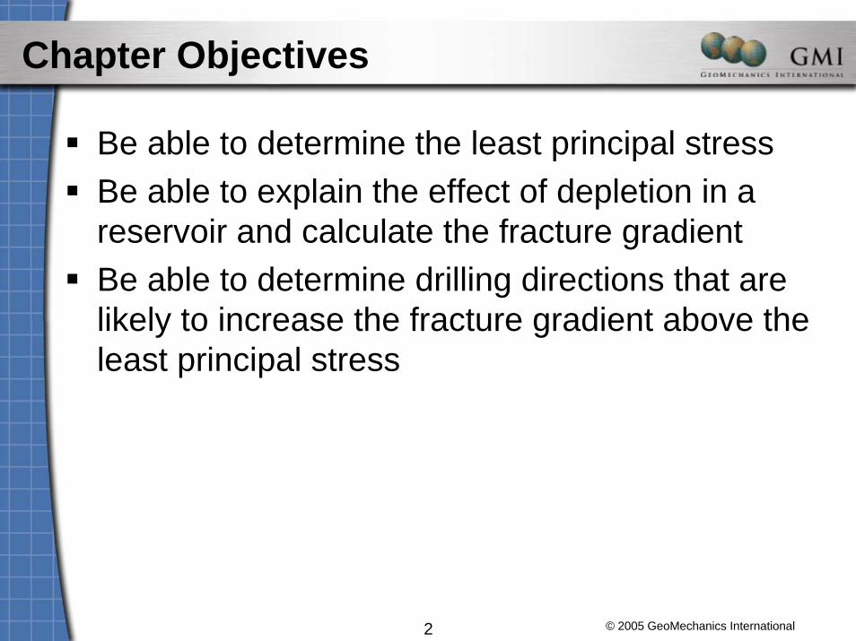
Be able to determine the least principal stressBe able to explain the effect of depletion in a reservoir and calculate the fracture gradientBe able to determine drilling directions that are likely to increase the fracture gradient above the least principal stress

LeakLeak--off Testsoff Tests

© 2005 GeoMechanics International4
Least Principal Stress (Shmin) from XLOT
(after Gaarenstroom et al., 1993)volume

© 2005 GeoMechanics International5
Typical Extended Leak-off Test
Shut-in

© 2005 GeoMechanics International6
Hydraulic Fracturing
• For an impermeable rock a sharp peak pressure (i.e., fracture breakdown) is often seen.
• For a permeable formation wellbore fluids can continuously percolate into the formation, hence, making a sharp peak pressure difficult to develop. Usually, a gradual inflection point is seen, which may be interpreted as fracture initiation.
• In a permeable formation a step-rate test may be preferred.
© 2005 GeoMechanics International7
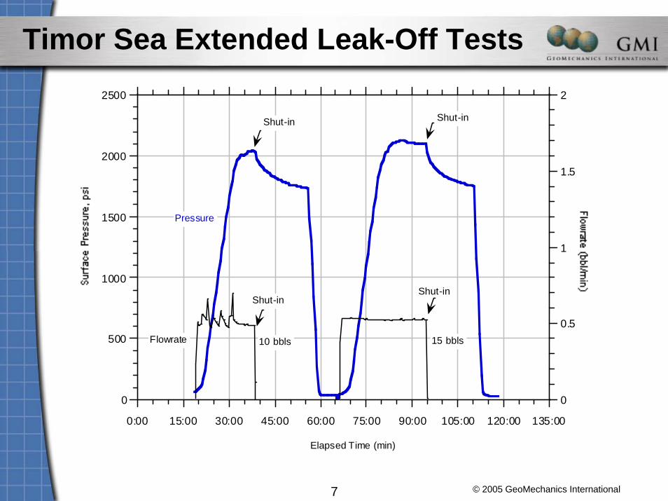
Timor Sea Extended Leak-Off Tests
0
500
1000
1500
2000
2500
0
0.5
1
1.5
2
0:00 15:00 30:00 45:00 60:00 75:00 90:00 105:00 120:00 135:00
Elapsed Time (min)
Pressure
Flowrate
Shut-in
10 bbls 15 bbls
Shut-in
Shut-in Shut-in

© 2005 GeoMechanics International8
Shut-In Pressure – S3 ≅ 1,940 psi
1700
1750
1800
1850
1900
1950
2000
2050
0 5 10 15 20 25 30
First Cycle
time after shut in
ISIP
1700
1750
1800
1850
1900
1950
2000
2050
0 5 10 15 20 25 30
Second Cycle
ISIP
© 2005 GeoMechanics International9
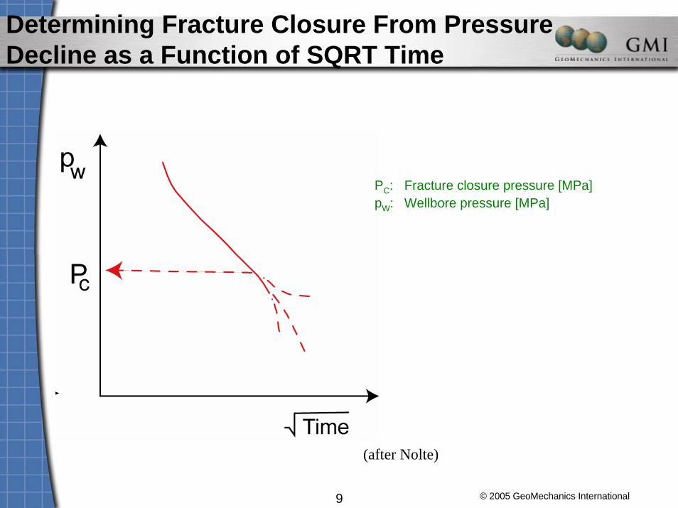
Determining Fracture Closure From Pressure Decline as a Function of SQRT Time
(after Nolte)
PC: Fracture closure pressure [MPa]pW: Wellbore pressure [MPa]

© 2005 GeoMechanics International10
Fracture Closure Pressure – S3 ≅ 1900 psi
1750
1800
1850
1900
1950
2000
2050
0 1 2 3 4 5 6 7 8
Cycle 2
Sqrt time
Closure Pressure
1700
1750
1800
1850
1900
1950
2000
2050
0 1 2 3 4 5 6 7 8
First Cycle
Sqrt time (min)
Closure Pressure

© 2005 GeoMechanics International11
Plot of Shmin From Leak-Off Tests
Leak-off tests provide accurate and consistent measurements if performed and analyzed consistently.

Lost CirculationLost Circulation

© 2005 GeoMechanics International13
Traditional Fracture Pressure Calculations
• Stress Ratio Methods
• Poisson's Ratio Methods
• Empirical Methods
• Tectonic Stress Methods
• Porosity Methods
• Frictional Equilibrium Methods
© 2005 GeoMechanics International14
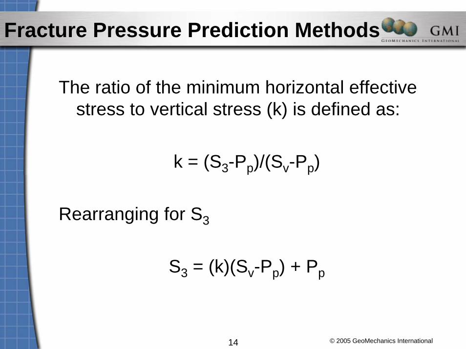
Fracture Pressure Prediction Methods
The ratio of the minimum horizontal effective stress to vertical stress (k) is defined as:
k = (S3-Pp)/(Sv-Pp)
Rearranging for S3
S3 = (k)(Sv-Pp) + Pp
© 2005 GeoMechanics International15
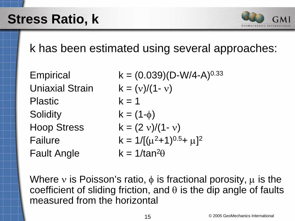
Stress Ratio, k
k has been estimated using several approaches:
Empirical k = (0.039)(D-W/4-A)0.33
Uniaxial Strain k = (ν)/(1- ν)Plastic k = 1Solidity k = (1-φ)Hoop Stress k = (2 ν)/(1- ν)Failure k = 1/[(μ2+1)0.5+ μ]2Fault Angle k = 1/tan2θ
Where ν is Poisson’s ratio, φ is fractional porosity, μ is the coefficient of sliding friction, and θ is the dip angle of faults measured from the horizontal

© 2005 GeoMechanics International16
Hubbert & Willis (1957)
S3 = 0.3 (Sv – Pp) + Pp
Where 0.3 is an estimate of the maximum ratio of horizontal to vertical stress. A later amendment increased the ratio coefficient to 0.5
Sv is the Overburden and Pp is the Pore Pressure
Results tend to be on the low side

© 2005 GeoMechanics International17
Matthews and Kelly (1967)(Most Generic Method)
S3 = Ki (Sv – Pp) + Pp
Where Ki = σh/ σv
Empirical regional values of Ki are needed tobe established from LOT calibrations

© 2005 GeoMechanics International18
Eaton (1969)
Fp = (ν /1- ν)(Sv – Pp) + Pp
Where ν = Poissons Ratio
Eaton Replaced Ki with a value calculated from Poisson's Ratio
Empirical regional values of ν are needed tobe established from LOT calibrations

© 2005 GeoMechanics International19
Anderson et al. (1973)
Fp = (Sv(2ν/1-ν))+((1-2ν/1-ν)(αPp))
Where α = 1-(1-φD)n
And ν is related to the lithology where theShaliness = (φS- φD)/ φS and
φS is the sonic and φD is the density porosity
Attributes fracture gradient variationsTo changes in lithology
Empirical regional values of α and ν are needed tobe established from LOT calibrations

© 2005 GeoMechanics International20
Cesaroni et al. (1981)Formations with elastic behavior (sandstones)
Fp = ((2ν/1-ν)(SV – Pp)) + Pp
Elastic formations with deep invasion (unconsolidated sands)
Fp = 2ν(SV – Pp) + Pp
Plastic formations (shale, marl, salt, etc)
Fp = SV
Where ν is 0.25 for clean sands and unfractured carbonates at shallow depth and 0.28 for shaly sands, carbonates and sandstones at greater depth.
© 2005 GeoMechanics International21
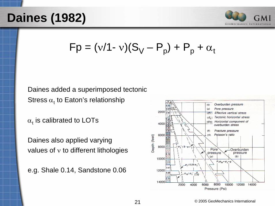
Daines (1982)
Fp = (ν/1- ν)(SV – Pp) + Pp + αt
Daines added a superimposed tectonic Stress αt to Eaton’s relationship
αt is calibrated to LOTs
Daines also applied varyingvalues of ν to different lithologies
e.g. Shale 0.14, Sandstone 0.06

© 2005 GeoMechanics International22
Pilkington (1978)
Fp = Ka (Sv – Pp) + Pp
Where Ka represents the statistical meanof the values of Ki and ν/1- ν used by previous authors
Ka substitutes Ki in Matthews and Kelly’srelationship

© 2005 GeoMechanics International23
Breckels & Van Eekelen (1981)(Only Valid in Areas with Established Relationships)
Empirical Relationship
Gulf Coast Relationship
Fp = 0.053 Z1.145 + 0.46(P – Pn)For Z < 3500m
Fp = 0.264 Z –317 + 0.46(P – Pn)For Z > 3500m
Where Z is the depth and Pn is the normalPore pressure
Also established relationships for N.Sea,Venezuela and Brunei

© 2005 GeoMechanics International24
Bryant (1983)
Fp = Ki (SV – Pp) + Pp
Modifies Ki in Matthews and Kelly relationship to take into account the contribution of pore pressure to the the mechanical properties of the matrix
If Pp < 1.4Pn, (low to moderate overpressure), Matthews and Kelly relationship is used
If Pp > 1.4Pn, (moderate to high overpressure), Ki is obtained from Ki = P/S

© 2005 GeoMechanics International25
Holbrook (1990)
(Use Only Recommended in Actively Compacting Formations in Tectonically Inactive
Areas)
Fp = ((1-φ)(SV – Pp)) + Pp
Replaces Ki or Poisson's ratio with a porosity term

© 2005 GeoMechanics International26
Important Limitations/Problems of Traditional Methods
• Most commonly used fracture gradient prediction methods assume the absence of tectonic stresses. (Applicable in GOM, Nile Delta, but not many other places)
• Poisson’s ratio methods are based on erroneous assumptions.
How to Determine S3?
• If S3 measurements are available (from LOT, minifrac, step rate test, circulation losses, ballooning), then use Matthews and Kelly(S3 = Ki (Sv – Pp) + Pp)Ki is calculated at depth(s) of S3 measurement(s).
• If no S3 measurements are available ⇒
© 2005 GeoMechanics International27
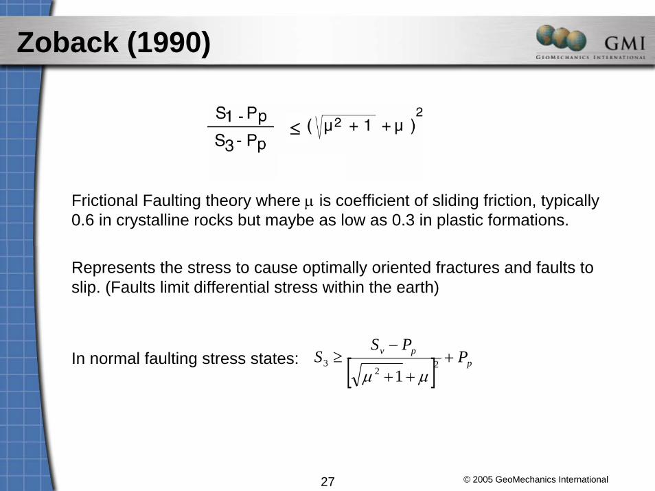
Zoback (1990)
Frictional Faulting theory where μ is coefficient of sliding friction, typically 0.6 in crystalline rocks but maybe as low as 0.3 in plastic formations.
Represents the stress to cause optimally oriented fractures and faults to slip. (Faults limit differential stress within the earth)
In normal faulting stress states: [ ] ppv P
PSS +
++
−≥ 2
23
1 μμ
≤

© 2005 GeoMechanics International28
Travis Peak Stress State is Consistent with a Crust in Frictional Equilibrium
12.3PS
PS
pminh
pv =−
−

© 2005 GeoMechanics International29
Impact of Water Depth on Fracture Gradient3,000 ft water depthonshore 6,000 ft water depth
Pore pressure (hydrostatic)
Frac gradient
Overburden (based on a constant density of 2.1 g/cm3)
Increasing water depth reduces the fracture gradient due to the difference between density of rock vs water (approx 9 ppg). The problem gets acute in ultra deepwater when the fracture gradient cannot support columns of mud even slightly heavier than water.
sea floor
sea floorMud Window becomes very narrow near the sea floor, which requires additional casing strings.

© 2005 GeoMechanics International30
Fracture Gradient in Weak, Unconsolidated Sediments (1)
Because of their viscous nature, weak and unconsolidated sediments cannot support any differential stress over a long period of time.
Wilmington Sand Stress Relaxation

© 2005 GeoMechanics International31
Fracture Gradient in Weak, Unconsolidated Sediments (2)
Weak, unconsolidated sediments cannot support any differential stress over a long period of time.
As a result, no difference exists between S3 and Sv in unconsolidated sediments.
=> S3 and therefore the fracture pressure is very close to the overburden in unconsolidated sediments.
Unconsolidated sediments
PressureD
epth
Overburden
Pore pressure
Least principal stress

© 2005 GeoMechanics International32
How to Determine S3 Versus Depth Profiles
• If S3 measurements are available (from LOT, minifrac, step rate test, circulation losses, ballooning), then use Matthews and Kelly(S3 = Ki (Sv – Pp) + Pp)Ki is calculated at depth(s) of S3 measurement(s).
• If no S3 measurements are available
– Look for measurements in offset fields
– Tectonic regime from active geologic structures(determine whether S3 << Sv or S3 ~ Sv)
– Use lower bound on S3 from Frictional Faulting Theory (next slide)
– In viscoelastic/viscoplastic formations (shaley, poorly consolidated) S3 ~ Sv
Drilling Into Depleted ReservoirsDrilling Into Depleted Reservoirs

© 2005 GeoMechanics International34
Poro-Elastic Response to a Change of Pp
Using instantaneous application of force and pressure with no lateral strain:
( )pvpH PSPS Δ−Δ⎟⎠⎞
⎜⎝⎛
−=Δ−Δ
ννα
1
( )( ) pH P1
21S Δν−ν−
α=Δ
Pp32SH Δ=Δ1,25.0 == ανif
g
b
KK
−=1α
Sv
SH
0L: Length (lateral extent) of reservoir [m]H: Height (thickness) of reservoir [m]ΔPP: Change in pore pressure [MPa]ΔSH: Change in horizontal stresses [MPa]SH ≡ Shmin ≡ SHmax
ν: Poisson’s ratioα: Biot’s coefficient
Kb: Bulk modulus of rock [GPa]Kg: Bulk modulus of individual grains [GPa]

© 2005 GeoMechanics International35
Ekofisk Field
© 2005 GeoMechanics International36
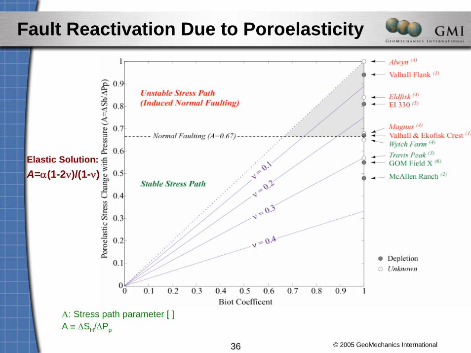
Elastic Solution:A=α(1-2ν)/(1-ν)
Α: Stress path parameter [ ]A ≡ ΔSH/ΔPp
Fault Reactivation Due to Poroelasticity

© 2005 GeoMechanics International37
Mud Window Size
Depleted sand
In some cases it may be necessary to case off the depleted sand to avoid circulation losses.
Does a Depleted Sand Increase the Risk for Lost Circulation? (Example from the GOM)

© 2005 GeoMechanics International38
Drilling Depleted Reservoirs –Planning Ahead
Time
Pre
ssur
e
Sv
Pp
Shmin
Collapse MW in shalesECD
Constant lossesNo losses Few losseswith careful ECD control
ECD: Equivalent circulating density

Increasing Mud Weights AboveIncreasing Mud Weights AboveThe Least Principal StressThe Least Principal Stress

© 2005 GeoMechanics International40
Lost Circulation Occurs if all of the Following Three Conditions are True
1. The borehole pressure is large enough to initiate a tensile fracture at the wellbore wall (or a pre-existing fracture is present).
• Borehole pressure necessary to initiate a tensile fracture depends on in-situ stress state, Pp, borehole orientation, (and tensile strength).
2. Fractures at the wellbore wall can be “linked up” to form one large, pervasive fracture through which significant quantities of fluid can escape.
• depends on in-situ stress state, and borehole orientation.
3. A fracture is propagated into the formation.
• Requires that fluid pressure at fracture tip exceeds the minimum horizontal stress
• Depends on Shmin and mud properties (mud invasion factor)

© 2005 GeoMechanics International41
Fracture Initiation - Stress Concentration Around a Vertical Well
A fracture is initiated when σθθmin drops below the tensile
strength of the formation
P0: Pore pressure [MPa]σθθ: Circumferential stress [MPa]σzz: Axial stress [MPa]

© 2005 GeoMechanics International42
Example for Occurrence of Drilling-Induced Tensile Fractures
Hypothetical Stress States, Hydrostatic
Pore Pressure
Normal Faulting
Normal/Strike-Slip Faulting
For comparison: Shmin = 12.95 ppg

© 2005 GeoMechanics International43
Inclined Tensile Cracks – Geothermal Well, Japan (Introduction to Fracture Link-Up)

© 2005 GeoMechanics International44
Modeling Inclined Tensile Fractures

© 2005 GeoMechanics International45
Example of Modeling the Occurrence of Lost Circulation Events
Hypothetical Stress States, Hydrostatic
Pore Pressure
Normal Faulting
Normal/Strike-Slip Faulting
For comparison: Shmin = 12.95 ppg
Fracture Initiation Fracture Link Up

© 2005 GeoMechanics International46
Propagation of a Mode I Fracture
Pp: Pore pressure [MPa]
S3: Minimum stress [MPa]
L: Fracture length [m]
Ki: Stress Intensity Factor

© 2005 GeoMechanics International47
Step Rate
Propagation pressure is negligible at higher flow rates because of low tensile strength and high stress intensity factor

© 2005 GeoMechanics International48
Definition of the Invaded Zone
PgrowPpPp
S3
S3
Mud plug
Penny shapedfracture
2R1
2R
Definition of the invaded zone (2R1) where the internal pressure is Pgrow and the non-invaded zone (R – R1) where the internal pressure is Ppduring fracture growth.
Pgrow − S3
S3 − Pp
=1
1 − 1 −R1
R⎛ ⎝ ⎜
⎞ ⎠ ⎟
21 −
R1
R⎛ ⎝ ⎜
⎞ ⎠ ⎟
2
+π
4 RK IC
S3 − Pp
⎛
⎝ ⎜ ⎜
⎞
⎠ ⎟ ⎟
© 2005 GeoMechanics International49
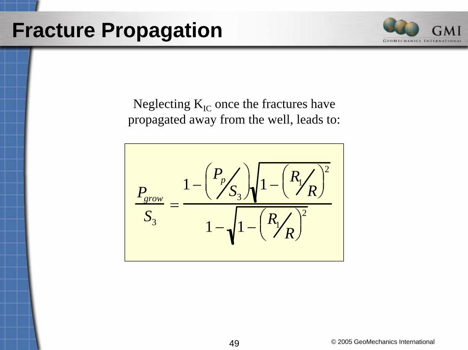
Fracture Propagation
Neglecting KIC once the fractures have propagated away from the well, leads to:
Pgrow
S3
=1 −
PpS3
⎛ ⎝ ⎜
⎞ ⎠ ⎟ 1 − R1
R⎛ ⎝ ⎜ ⎞
⎠ ⎟ 2
1 − 1 − R1R
⎛ ⎝ ⎜ ⎞
⎠ ⎟ 2

© 2005 GeoMechanics International50
Lost Circulation Occurs if all of the Following Three Conditions are True
1. Borehole pressure exceeds fracture Initiation pressure
⇒ Should only be used with caution as upper bound!
2. Borehole pressure is large enough for fractures to link up
⇒ Good upper bound if stress field is well known
3. A fracture is propagated into the formation.
⇒ Most conservative upper bound. Can be constrained with extended leak off test.
Case Study:Case Study:Deep Water Gulf of Mexico Deep Water Gulf of Mexico –– Maximizing Maximizing
Fracture GradientFracture Gradient

© 2005 GeoMechanics International52
Overcoming Near Wellbore Stresses

© 2005 GeoMechanics International53
Increasing Fracture Pressure

© 2005 GeoMechanics International54
Increasing Fracture Pressure in a Deviated Well

© 2005 GeoMechanics International55
Further Reading
Hubbert, M. K., and D. G. Willis, 1957. Mechanics of hydraulic fracturing, AIME Trans., 210, 153–163.Ito, T., M. D. Zoback, and P. Peska, 2001. Utilization of mud weights in excess of the least principal stress in extreme drilling environments, SPE Drilling and Completion, December 2001, SPE 57007.Nolte, K. G. and M. J. Economides, 1989, Fracturing diagnosis using pressure analysis, in Reservoir Simulation, M. J. Economides and K. G. Nolte, eds., Prentice Hall: Englewood Cliffs, N.J.Ward, C. D., and M. Beique, 1999. How to identify Lost Circulation Problems with Realtime Pressure Measurement: Downhole Pressure Sensing heads off Deepwater Challenge, Offshore, August 29.
Related Documents