EP 2002-1500 - 89 - Restricted to Shell Personnel Only 4. WELL CONTROL EQUIPMENT SURFACE 4.1. The Well Kill System The Well Kill System is comprised of various rig components, many of which are permanently installed and in most cases have daily routine functions. This section highlights their involvement in the kill process and makes recommendations on their specification and dimensions. 4.1.1. Schematic (an example of many possible alternatives) Reserv Pits Pump #1 Pump #2 Cmt Pump Active To Flare Drop-In Dart Kelly Cock IBOP FOSV To Vent Mud -Gas Separator Kill&Choke Line Manifold Choke Manifold NRV De -gasser Header Tank Stripping Tank Trip Tank BOP 4.1.2. Tankage Mud Pit Management The guidelines given below refer to ideal situations where local circumstances, size of rig, type of well, design of well, equipment availability and other limitations are not an issue. The decision to say, increase the size of reserve tanks or mixing speed to comply with these guidelines should reflect local circumstances. The key element is to maintain control by utilising available resources to the best advantage by pre-planning and good mud pit management. A set of very specific procedures should be developed locally when a set of standard equipment components are not available. Factors to consider may include: • The total volume of mud after circulating out a kick without weighting up (Driller’s method) will be the same as before the kick was taken. • As a gas kick is circulated up the hole, it may expand, causing an increase in pit volume. • As a gas kick is circulated out of the hole through the choke and vented, there will be a decrease in pit volume to the pre-kick volume. • It is important to monitor these variations which, if irregular, may indicate losses. Before circulating out a kick by the Driller’s method, reduce the active system to effectively one pit. The total pit capacity should be capable of accommodating a potential pit gain due to gas expansion and accommodate a level drop due to volume replacement of vented gas or reservoir fluid.

Welcome message from author
This document is posted to help you gain knowledge. Please leave a comment to let me know what you think about it! Share it to your friends and learn new things together.
Transcript

EP 2002-1500 - 89 - Restricted to Shell Personnel Only
4. WELL CONTROL EQUIPMENT � SURFACE
4.1. The Well Kill System
The �Well Kill System� is comprised of various rig components, many of which arepermanently installed and in most cases have daily routine functions. This sectionhighlights their involvement in the kill process and makes recommendations on theirspecification and dimensions.
4.1.1. Schematic (an example of many possible alternatives)
Reserv Pits
Pump #1 Pump #2
Cmt Pump
Active
To Flare
Drop-InDart
Kelly Cock
IBOPFOSV
To Vent
Mud - GasSeparator
Kill&ChokeLine Manifold
ChokeManifold
NRV
De - gasser
HeaderTank
Stripping Tank
Trip Tank
BOP
4.1.2. Tankage
Mud Pit ManagementThe guidelines given below refer to ideal situations where local circumstances, size of rig,type of well, design of well, equipment availability and other limitations are not an issue.The decision to say, increase the size of reserve tanks or mixing speed to comply with theseguidelines should reflect local circumstances. The key element is to maintain control byutilising available resources to the best advantage by pre-planning and good mud pitmanagement. A set of very specific procedures should be developed locally when a set ofstandard equipment components are not available. Factors to consider may include:
• The total volume of mud after circulating out a kick without weighting up (Driller'smethod) will be the same as before the kick was taken.
• As a gas kick is circulated up the hole, it may expand, causing an increase in pitvolume.
• As a gas kick is circulated out of the hole through the choke and vented, there will bea decrease in pit volume to the pre-kick volume.
• It is important to monitor these variations which, if irregular, may indicate losses.
Before circulating out a kick by the Driller's method, reduce the active system to effectivelyone pit. The total pit capacity should be capable of accommodating a potential pit gain dueto gas expansion and accommodate a level drop due to volume replacement of vented gasor reservoir fluid.

EP 2002-1500 - 90 - Restricted to Shell Personnel Only
• If weighting up is required, the volume will increase by the volume of the weightmaterial added.
• An efficient kill will be the one that initially weights up only the hole volume and aminimum surface circulating volume.
• Weighting up should proceed in reserve pits during the first circulation of theDriller's method only if they can be managed to advantage. It is best to prepareweighted mud in a reserve pit that has direct mud pump suction and can take returnsdirect from the degassed mud pit. It may be necessary to segregate tanks in the activesystem to achieve this set-up.
• Weighting up can proceed in the active suction pit during the wait period of the Wait& Weight method.
Before preparing weighted mud for either kill method, reduce the mud volume in the pit tothe lowest practical level. This will facilitate faster initial weighting but will have no effecton the pump rate at which the kill can proceed. Pump rate will be governed by the rate atwhich weight material can be added to the mud returning from the hole.
Active Pit
• The �Active� pit should be large enough to hold an adequate working volume of fluidyet small enough so that a small influx can easily be detected due to an increase inmud level.
• Any pit to be used as the �Active� must be equipped with accurate fluid levellingdevices.
• Wherever possible, the pit levelling devices should be alarmed (visual & audible tothe driller) to indicate flow from the well.
• For floating rigs, consider a levelling device in each corner of the pit with averagedoutput, to compensate for rig pitch and roll.
• If a mud-logging contractor is to be used, an ultra-sonic levelling system isrecommended.
Reserve Pits
• The reserve system should be large enough to accommodate all surface volumesrequired in the course of the well.
• Provision must be made for increases in volume due to weighting-up.
• The mud mixing system (hoppers, jet-guns etc.) should be adequate to allow fastdensity changes to large volumes of mud (i.e. a hole volume).
• The system of valves and transfer lines must be such that pit-management is simpleand efficient.
Kill Pit
• Normally confined to critical wells (HPHT etc.) where the risk of a kick is high.
• Normally large enough to hold a full well volume of mud weighted to maximumanticipated kill weight plus a safety margin.

EP 2002-1500 - 91 - Restricted to Shell Personnel Only
• May also be used to hold �Tripping Mud�, on wells where low fracture marginsrequire a dual system.
Trip Tank
• Primarily use to monitor hole fill and returns while tripping.
• The trip tank shall be provided with an accurate fluid level indicator or arecorder/indicator, showing the amount of mud used to keep the hole full whenpulling pipe, and the amount of mud returned when running in. It should also bepossible to monitor hole fill/flow during static conditions such as electric loggingoperations.
• Used for accurate volumetric flow-checks, particularly on floating rigs.
• Must have a small cross-section so that volume changes are easily detected andaccurately quantified.
• An indicating and recording mud pit level system, capable of providing early visualand audible warning of gain or loss of fluid in the well, shall be installed in thosemud tanks which serve as active mud tanks.
• There should always be a redundancy in measuring trip tank levels i.e. Drillers shoulduse their own (mechanical) devices as well as those from other systems (eitheracoustic or ultra-sonic). Apart from accuracy, the importance of understanding whydiscrepancies exists and how they should be interpreted should be stressed.
• Multiple levelling devices must not interfere with each other�s operation (i.e. a floatgiving a false signal to a sonic sensor).
• Volume changes must be easily monitored from the Driller's position.
Stripping Tank
• A small secondary tank to the trip tank used to measure fluid transferred from thetrip tank while stripping.
• Must have a small cross section so that volume changes can be accurately measured.
4.1.3. Pumps
Mud Pumps
• Prior to spudding, the drilling mud pumps, mud manifolds, valves and maindischarge lines shall be pressure tested with water to 34,500kPa (5000psi) or thecirculating system working pressure if it is higher e.g. (7500psi).
• In all cases, a minimum of two pumps must be available to allow for redundancy.
• Hydraulic output must be sufficient to circulate maximum anticipated kill weightmud at planned well profile and worst-case geometry.
• Functional stroke counters must be installed to monitor displacement.

EP 2002-1500 - 92 - Restricted to Shell Personnel Only
Cement Pump
• The emergency high pressure kill pump (and/or the cement pump), manifolds,valves and lines shall be tested to the maximum rated working pressure of the lowestrated part of the system.
• The cement pump may be required during kill operations as a back-up to the mudpumps.
• Ideally, the cement pump will have an independent power source (diesel) in the eventof total power loss.
• Functional stroke counters or flow/volume measuring devices must be installed tomonitor displacement.
4.1.4. Drill String Shut off Devices
Kelly Cock
• The kelly cock is used to prevent flow up the drill pipe.
• On a kelly-rig, two kelly cocks are used, one above the kelly saver-sub (Full OpeningSafety Valve (FOSV)) and the other, with LH threads, below the swivel (i.e. one ateither end of the kelly itself).
• The left-hand threaded upper FOSV shall be in good operating condition at all times.A test sub for testing the kelly or top drive and kelly cocks shall be available on thedrilling rig.
• The hexagonal wrench (Allen Key) used to operate the kelly cock must be availableon the rig floor at all times.
• Top-drive rigs generally have one kelly cock (IBOP) positioned below the TDS andwhich is remotely operated from the Driller's position.
• The IBOP of a top drive should be hydraulically operated.
• It should be possible to break the connection above the IBOP of the top drive andremove the top drive when string entry below the top drive is required with the wellunder pressure.
Stab In Valve (FOSV)
• The stab in valve is used to shut-off flow up the string while tripping (i.e. the kelly isracked)
• Three Full Opening Safety Valves (FOSV) for each size of drill pipe in use shall beavailable.
� One shall be used below the kelly or top drive during drilling operations,
� One shall be on the drilling floor complete with removable handles for easystabbing and connection and;
� One as a spare.
• The valve must be crossed-over to fit the pipe currently being run.
• Cross-overs must be available for all pipe and thread combinations being run. If thisis not possible or practical, alternate methods to control the well should be available,
EP 2002-1500 - 93 - Restricted to Shell Personnel Only
understood and practised (e.g. shearing the pipe or dropping the string). A methodof shearing and dropping the string should be possible in all cases as a redundancymethod, if the safety valve cannot be stabbed owing to location of connection(above the drill floor) or excessive flow.
• The valve and cross-over assembly must be full bore to the pipe being run so thatstabbing the valve does not present a restriction to flow from the well.
• The valve must always be in the full-open position until actually installed. The valveis closed after being made up and before the BOP is closed. The FOSV is openedafter installing the IBOP before stripping.
• Stabbing of the valve and cross-over assembly must be facilitated by either limitingthe size and weight to that that can be easily man-handled, or use of un-poweredmechanical means such as a counterweight device.
• FOSV's have been known to fail under external pressure differential and hence maynot be appropriate for high pressure stripping operations.
Inside BOP or IBOP
• The inside BOP is a non-return valve contained in a sub that can be made up in thedrill string.
• A 'Gray-type' inside BOP (IBOP), with the appropriate connections for the drillstring in use, shall be on the drilling floor at all times. It shall be ready for immediateuse.
• It is always made up above the FOSV when stripping is required or may be stabbeddirectly onto the drill string in place of the FOSV.
• Practical considerations for use are similar to the FOSV with the exception that onceit is installed there is no longer wireline access to the drill string below it, neither canpump-down devices be used.
Drop-in Sub (DIS)
• This term applies to a number of devices, which are dropped into the pipe at surfaceand locate in a dart-sub in the BHA. Their function is to prevent flow up the string,working as a one-way check valve.
• When drill string float valves are not run, two drop-in type back-pressure valves(NRV) must be available. These are to be complete with seating subs to fit the drillstring in the hole. The drop-in valves must be able to pass the smallest bore in thedrill string above the seating sub, and preferably be wireline retrievable.
• If a dart-sub is being run, the drift of the BHA and pipe above it must be checked toensure that the dart can land.
• A Drop In Sub should be installed in the string when drilling with total losses or witha floating mud cap. The dart of the DIS should be dropped and pumpeddown/latched prior to each trip.
• In a well control situation, the string should never be broken specifically to drop adart except in extreme circumstances where loss of containment at surface is likely.
• A drill pipe float valve run in the bit sub provides a 'permanent' non return functionduring trips and connections.

EP 2002-1500 - 94 - Restricted to Shell Personnel Only
Circulating Head
• A 69,000kPa (10,000psi) WP 76.2mm (3") rotating type circulating head with correctbottom subs for the drill string sizes in use shall be available on the drilling floor
• A casing circulating head with a pressure rating equal to the casing rating shall beavailable on the drilling floor throughout casing running operations.
Any item for shut off in an emergency shall match the tool joints in use and be tested onthe same routine frequency as the BOP stack.
4.1.5. The BOP
• The function of the BOP is to seal-off the annulus to divert flow from the well tothe choke manifold.
• The BOP rating and ram configuration will be determined by well conditions and theproposed activity. The equipment and example stack-ups are discussed in Section4.2.
4.1.6. Down Stream Equipment
Choke Manifold
• The choke is a device which allows gas and fluids to be released from the well at acontrolled rate and pressure
• Ideally, two chokes should be available, particularly on critical wells. This will allowwashed out or plugged choke devices to be changed without stopping the kill.
• A glycol injection point should be available to prevent hydrate build-up resultingfrom cooling caused by gas expansion through the choke. See Section 4.7.
Mud-Gas Separator (�Poor Boy�)
• The Mud-Gas Separator (MGS), is the first device down stream of the choke duringwell control operations. It is not a part of the normal circulating system.
• It is essentially a gravity separation tank where the mud is briefly unconfined andflows across a series of baffles. This allows gas bubbles to breakout at the surface ofthe mud and pass up the vent line.
• Mud is effectively drawn off from the lowest part of the separating chamber of thetank through the mud leg (liquid seal, U tube) on route to the header tank.
• Gas is vented through a large diameter line usually secured to the derrick.
• Must be fitted with a low pressure gauge 100kPa (15psi) which should be visiblefrom the choke control console and preferably alarmed.See Section 4.6.
Flowline
• Although not strictly part of the kill system, the flow line is an important location forkick detection.

EP 2002-1500 - 95 - Restricted to Shell Personnel Only
• The �traditional� mud-flow paddles are poor in angled flow-lines. Wherever possiblethey must be located at the downstream end of a horizontal section, to allow theflow to settle.
• Flow sensors in general, are unreliable on floating rigs due to vessel motion.
Header Tank
• Entrained gas downstream of the MGS is monitored at the header tank, normally bythe mudlogging contractor.
• If on contract, mud weight, mud temperature and H2S sensors should also belocated here.
Vacuum De-Gasser (or Mechanical Atmospheric De-Gasser)
• The primary function of these Vacuum or Centrifugal De-Gassers is the removal ofdissolved or entrained gas from the mud system. They are part of the normalcirculating system and can be used at any time to treat gas-cut or aerated mud
• In simple terms they work by subjecting the mud to a mechanically induced pressuregradient, which allows gas to break out of the mud.
• Mud can carry high levels of entrained and/or dissolved gas for many circulationsthrough the MGS, therefore the De-Gasser is required to reduce levels prior to themud returning to the active pit.See Section 4.6.
4.2. Surface Well Control Equipment
This section lays out the basic requirements of well control equipment for a typical surfaceinstallation and reviews the philosophy for BOP stack-up.
4.2.1. General Issues
The following considerations should be made when selecting well control equipment:
• New BOP equipment shall have a rated working pressure (WP) in excess ofmaximum anticipated surface pressures. BOPs that have been fully refurbished andbody pressure tested to 50% above the rated work pressure are considered "new";
• Used BOPs (>5 years old) shall have a rated working pressure no less than 10% inexcess of maximum anticipated surface pressures;
• The BOP shall consist of remotely controlled equipment capable of closing in thewell with or without pipe in the hole. The remote control unit shoulddiagrammatically represent the stack-up arrangement. Valves, handles and buttons,which are not in use, should be removed;
• Welded, flanged, or hub connections are mandatory on all pressure systems with arated working pressure in excess of 13,800kPa (2000psi). Threaded connections arenot acceptable;
• In wells where H2S may be encountered, well control equipment suitable for sourservice is required; in such cases the complete high-pressure BOP system should befabricated of materials resistant to H2S and sulphide stress corrosion cracking.

EP 2002-1500 - 96 - Restricted to Shell Personnel Only
• Elastomers installed in BOPs must be appropriate for the mud systems used andtemperatures / fluids expected.
• Dedicated kill lines must not be smaller than 50mm (2") nominal and shall be fittedwith two valves and an NRV. Choke lines must not be smaller than 75mm (3")through bore and are to be connected with two valves to the BOP stack of which theouter valve shall be remote hydraulically operated.
• When dual purpose kill and choke lines are employed, both lines must not be smallerthan 75mm (3") through bore and the outer valve of each line shall be remotehydraulically operated. They shall both be connected to a Kill & Choke LineManifold that incorporates an NRV on the mud pump discharge line.
• During drilling and workover operations, shearing blind rams should be provided inthe BOP stack whenever feasible. The shearing blind rams should be capable ofshearing the drill pipe/tubing in use under no-load conditions and subsequentlyprovide an effective seal (forces required to shear common sizes of drill pipe areshown in Figure 4.2.1).
• Closing systems of surface BOPs should be capable of closing each ram preventerwithin 30 seconds. The closing time should not exceed 30 seconds for annularpreventers smaller than 508mm (20") and 45 seconds for annular preventers of508mm (20") and larger (see also API RP53).
• All master and remote operating panel handles should, at all times, be in the fullopen or closed position, and be free to move into either position, i.e. the shear ramoperating handles should not be locked but may be screened to prevent inadvertentoperation.
• All four way valves in operation should be either in the fully open or fully closedposition, as required; they should not be left in the blocked or centre position.
• All spare operating lines and connections, which are not use in the system should beblanked off with blind plugs at the hydraulic operating unit.
Pipe SizeDiameter Grade Weight Shear Force2-7/8� N-80 6.6. lb/ft 120,000 lbs
3-1/2� N-80 10.2 lb/ft 180,000 lbs
3-1/2� C-75 10.2 lb/ft 180,000 lbs
3-1/2� P-110 10.2 lb/ft 180,000 lbs
5� Grade E 19.5 lb/ft �std� 200,000 lbs
5� Grade E 19.5 lb/ft �soft� 295,000 lbs
5� G-105 19.5 lb/ft 375,000 lbs
5� S-135 19.5 lb/ft 375,000 lbs
5� X-95 25.6 lb/ft 480,000 lbs
Figure 4.2.1: Shearing Forces for Common Sizes of Drillpipe
Closing pressure = (Force required to shear)/(Closing Area)

EP 2002-1500 - 97 - Restricted to Shell Personnel Only
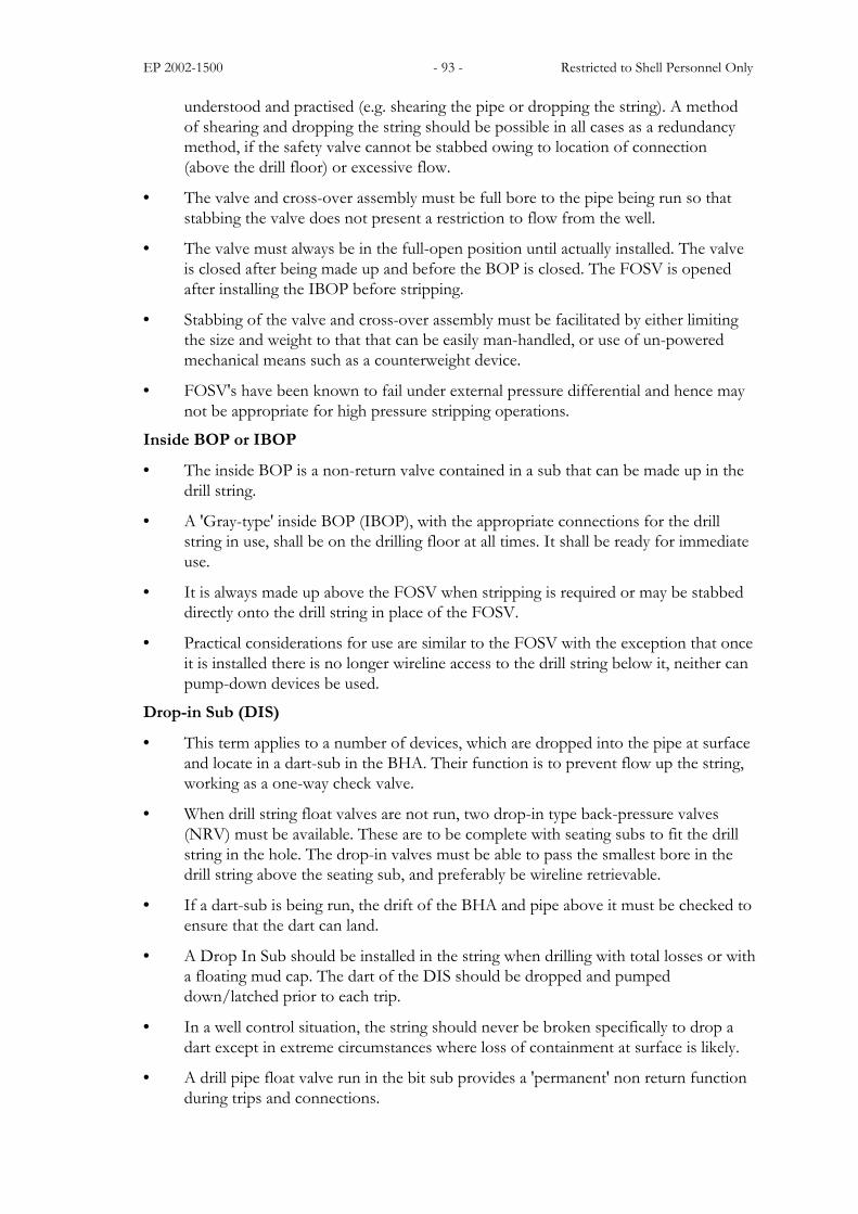
Note: Closing area of BOPs (with or without booster) can be obtained from the BOPmanufacturers engineering data. Some typical BOPs are listed in Figures 4.2.2 through to4.2.5
Closing areas of common BOPs
Size Type Pressure rating Weight lbs H� W� L�
7-1/16� Type U 3/5/10M 145 lbs 4.5� 7.5� 13�
11� Type U 3/5/10M 300 lbs 5.5� 12� 17.5�
13-5/8� Type U 3/5/10M 510 lbs 6� 15� 22�
13-5/8� Type T 10M 600 lbs 7.5� 16� 27�
16-3/4� Type U-II 5/10M 920 lbs 8� 17.5� 28�
18-3/4� Type U 5/10M 1250 lbs 11� 20� 27�
18-3/4� Type U-II 10/15M 1200 lbs 11� 20� 27�
18-3/4� Type T 15M 1200 lbs 11.5� 20� 27�
21-3/4� Type U 2/3M 980 lbs 8� 17.5� 30�
Figure 4.2.2: Cameron Shearing Blind Rams (SBRs)
Size Type Pressure rating Weight lbs H� W� L�
7-1/16� 5/10M 260 lbs 5� 8.5� 16�
13-5/8� 5M 675 lbs 6� 16� 26�
13-5/8� 10M 780 lbs 7� 19� 30�
18-3/4� 10M 1530 lbs 9� 23� 36�
18-3/4� 15M 1620 lbs 11� 24� 38�
20-3/4� 5M 900 lbs 7.5� 22� 40�
21-1/4� 3/5M 900 lbs 7.5� 22� 40�
Figure 4.2.3: Hydril Shear Rams
Size Type Pressure rating Weight lbs H� W� L�
7-1/16� Type U 3/5/10M 145 lbs 4.5� 7.5� 13�
11� Type U 3/5/10M 300 lbs 5.5� 12� 17.5�
13-5/8� Type U 3/5/10M 510 lbs 6� 15� 22�
13-5/8� Type T 10M 600 lbs 7.5� 16� 27�
16-3/4� Type U, U-II 5/10M 920 lbs 8� 17.5� 28�
18-3/4� Type U 5/10M 1200 lbs 11� 20� 27�
18-3/4� Type U-II 10/15M 1200 lbs 11� 20� 27�
18-3/4� Type T 15M 1200 lbs 11.5� 20� 27�
21-3/4� Type U 2/3M 980 lbs 8� 17.5� 30�
EP 2002-1500 - 98 - Restricted to Shell Personnel Only
Figure 4.2.4: Cameron �DS� Shear Rams
Size Type Pressure rating Weight lbs H� W� L�
7-1/16� Type SL/LWS 5/10/15M 150 lbs 3.5� 9.5� 14�
11� Type LWS 5M 330 lbs 3.5� 16� 18�
11� Type SL 10M 365 lbs 3.5� 16� 18�
13-5/8� Type LWS 5M 330 lbs 4� 16� 18�
13-5/8� Type SL 10M 510 lbs 5.5� 16� 18�
13-5/8� Type SL 15M 520 lbs 5.5� 16� 18�
16-3/4� Type LWS 5M 255 lbs 6� 20� 25�
16-3/4� Type SL 10M 530 lbs 6� 20� 25�
18-3/4� Type SL 10M 590 lbs 7� 24� 30�
18-3/4� Type SL 15M 565 lbs 6.5� 24� 36�
21-3/4� Type SL 2/3M 550 lbs 8� 26� 36�
Figure 4.2.5: Shaffer Shearing Blind Rams
4.2.2. Stack-up
The relative positioning of the blind rams, pipe rams and the kill and choke line outlets forsurface BOPs will depend on the well, the rig, the equipment available and the particularoperating conditions. Each stack-up has both advantages and disadvantages which shouldbe matched to the anticipated situation.
The sketches in the following sections show some of the options available. In each case:
Option a) would normally be preferred.
Option b) would be suitable only for special circumstances.

EP 2002-1500 - 99 - Restricted to Shell Personnel Only
4.2.3. Stack-up Options for Two-cavity-BOP
A. Two Single Ram Preventers1. When blind ram cannot shear the drill string.a) Position BR in lower cavity, PR/VBR in upper
cavity, Drilling spool or side outlets below both.Advantages:− Allows change of PR to CR above closed BR.− Allows installation of shooting nipple above
BR.Disadvantage:− Does not allow stripping tooljoints from
annular to PR. (Resolved by placing a spacerspool between annular and PR.)
b) Position PR/VBR in lower cavity, BR in uppercavity, Drilling spool or side outlets below both.Advantage:− Allows stripping tooljoints from annular to PR.Disadvantages:− CR installation only with PR blanking plug or
drill pipe in the hole.− CR installation removes BR from stack.− Cannot install shooting nipple above BR.
CASING
PIPE/VBR
ANNULAR
SPOOL
BLIND
2. When Shearing blind rams are available and they can shear the drill string.a) Position PR/VBR in lower cavity, SBR in upper
cavity. Drilling spool or spacer spool and side outlet betweenrams, and drilling spool or side outlet below both.Advantages:− Allows pipe hang-off and shear.− Allows stripping tooljoints from annular to PR.Disadvantages:− CR installation only with PR blanking plug or
drill pipe in the hole.− CR installation removes SBR from stack.− Cannot install shooting nipple above SBR− May Increase stack height.
ANNULAR
PIPE/VBR
SPOOL
SHEAR CASING
OUTLET
b) Position SBR in lower cavity, PR/VBR in uppercavity. Drilling spool or side outlets below both.
Advantages and disadvantages same as for A1a) above.i.e SBR not positioned for maximum benefit.
CASINGPIPE/VBR
SPOOL
SHEAR
ANNULAR
ANNULAR
CASING
BLIND
PIPE/VBR
SPOOL
EP 2002-1500 - 100 - Restricted to Shell Personnel Only
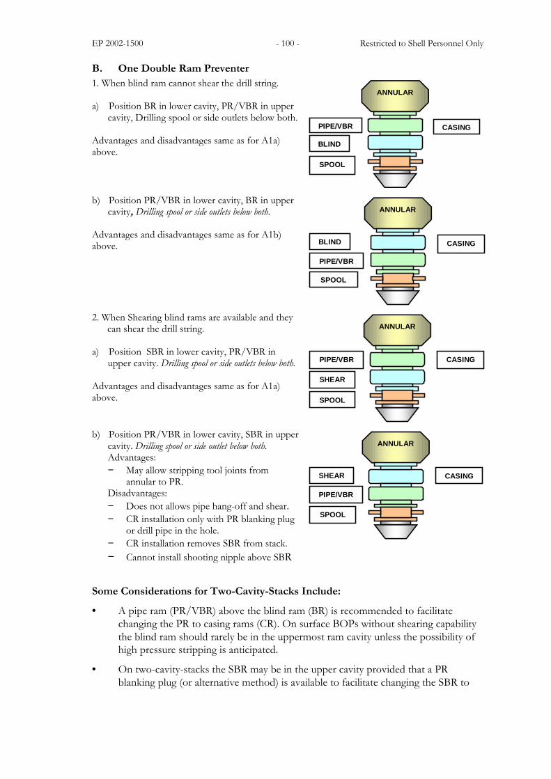
B. One Double Ram Preventer1. When blind ram cannot shear the drill string.
a) Position BR in lower cavity, PR/VBR in uppercavity, Drilling spool or side outlets below both.
Advantages and disadvantages same as for A1a)above.
ANNULAR
CASINGPIPE/VBR
SPOOL
BLIND
b) Position PR/VBR in lower cavity, BR in uppercavity, Drilling spool or side outlets below both.
Advantages and disadvantages same as for A1b)above.
ANNULAR
CASING
PIPE/VBR
SPOOL
BLIND
2. When Shearing blind rams are available and they can shear the drill string.
a) Position SBR in lower cavity, PR/VBR inupper cavity. Drilling spool or side outlets below both.
Advantages and disadvantages same as for A1a)above.
ANNULAR
CASINGPIPE/VBR
SPOOL
SHEAR
b) Position PR/VBR in lower cavity, SBR in uppercavity. Drilling spool or side outlet below both.Advantages:− May allow stripping tool joints from
annular to PR.Disadvantages:− Does not allows pipe hang-off and shear.− CR installation only with PR blanking plug
or drill pipe in the hole.− CR installation removes SBR from stack.− Cannot install shooting nipple above SBR
ANNULAR
CASING
PIPE/VBR
SPOOL
SHEAR
Some Considerations for Two-Cavity-Stacks Include:
• A pipe ram (PR/VBR) above the blind ram (BR) is recommended to facilitatechanging the PR to casing rams (CR). On surface BOPs without shearing capabilitythe blind ram should rarely be in the uppermost ram cavity unless the possibility ofhigh pressure stripping is anticipated.
• On two-cavity-stacks the SBR may be in the upper cavity provided that a PRblanking plug (or alternative method) is available to facilitate changing the SBR to
EP 2002-1500 - 101 - Restricted to Shell Personnel Only
CR, and, the stack-up dimensions will permit drill pipe hang off and shear. This willnormally only be possible with single rams separated by a spool.
• There should be a minimum of one complete drill pipe tool joint length (includingtapers) space between the top of the lowermost pipe ram and the bottom of theshearing blind ram. This is normally achieved with the drilling spool but may requirea spacer spool if side outlets are used. With this configuration a blowout up the drillstring may be shut off (sheared) without dropping the drill string.
• There should be a drilling spool or kill and choke side outlets below the lowermostram.
• When more than one set of kill and choke lines are installed, the uppermost arealways to be used first to maximise redundancy.
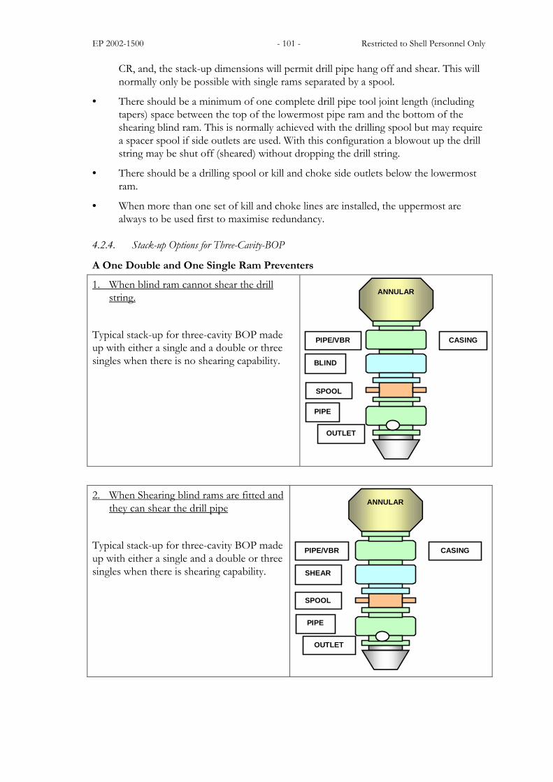
4.2.4. Stack-up Options for Three-Cavity-BOP
A One Double and One Single Ram Preventers
1. When blind ram cannot shear the drillstring.
Typical stack-up for three-cavity BOP madeup with either a single and a double or threesingles when there is no shearing capability.
ANNULAR
PIPE/VBR CASING
BLIND
SPOOL
PIPE
OUTLET
2. When Shearing blind rams are fitted andthey can shear the drill pipe
Typical stack-up for three-cavity BOP madeup with either a single and a double or threesingles when there is shearing capability.
ANNULAR
PIPE/VBR CASING
SHEAR
SPOOL
PIPE
OUTLET
EP 2002-1500 - 102 - Restricted to Shell Personnel Only
4.2.5. Use of Casing Rams
Casing rams (or appropriately sized VBRs) should be installed in the BOP when runningcasing whenever there may be hydrocarbon bearing or abnormally pressured water zonesopen in the well.
It is recognised that in certain situations, the safety of the well may be jeopardised whilechanging rams preparatory to running casing. In those cases where it is decided casing ramsshould not be installed, the following shall be on the rig floor made up, ready for use:
• a crossover from drill pipe to the casing;
• drill pipe matching the diameter of the pipe rams, of sufficient strength to supportthe casing weight;
• Full Opening Safety Valve;
• Inside BOP.
The possibility of dropping or shearing the casing, as a last resort, should also be assessed.
See Section 4.8 for guidelines on pressure testing Casing rams.
4.3. Classification of Well Control Equipment
Well control equipment falls into five basic rated working pressure (WP) classifications.1. 13,800kPa (2000psi) WP2. 20,700kPa (3000psi) WP3. 34,500kPa (5000psi) WP4. 69,000kPa (10,000psi) WP5. 103,500kPa (15,000psi) WP
4.3.1. Surface BOP Equipment (Definition)
Surface blowout prevention equipment is that equipment used in land operations and inoffshore operations where the wellhead is above the water level. Given below are theMINIMUM requirements for each rated working pressure classification.
4.3.2. 13,800kPa (2000psi) WP classification
Where equipment of this classification will suffice, the minimum BOP stack will consist of:
Either;
1. A double hydraulic operated ram type preventer (one equipped with correct size pipeor variable bore rams, the other with blind rams) and one full opening drilling spoolwith two 77.8mm (3-1/16") bore side outlets.

EP 2002-1500 - 103 - Restricted to Shell Personnel Only
2K ALTERNATIVE 1.
DRILLING SPOOL
SBR
PR/VBR
3
1 42 1
CASING HEAD HOUSING
76.2mm (3") GATE VALVE
76.2mm (3") HYDRAULICALLY OPERATED CHOKE LINE VALVE
50.8mm (2") GATE VALVE 3
2
1
NON RETURN VALVE 4
Or
2. One annular preventer capable of full closure and one full opening drilling spoolwith two 77.8mm (3-1/16") bore side outlets.
1 42 1 ANNULAR
DRILLING SPOOL
3
CASING HEAD HOUSING
76.2mm (3") GATE VALVE 76.2mm (3") HYDRAULICALLY OPERATED CHOKE LINE VALVE
50.8mm (2") GATE VALVE 3
2
1
NON RETURN VALVE4
EP 2002-1500 - 104 - Restricted to Shell Personnel Only
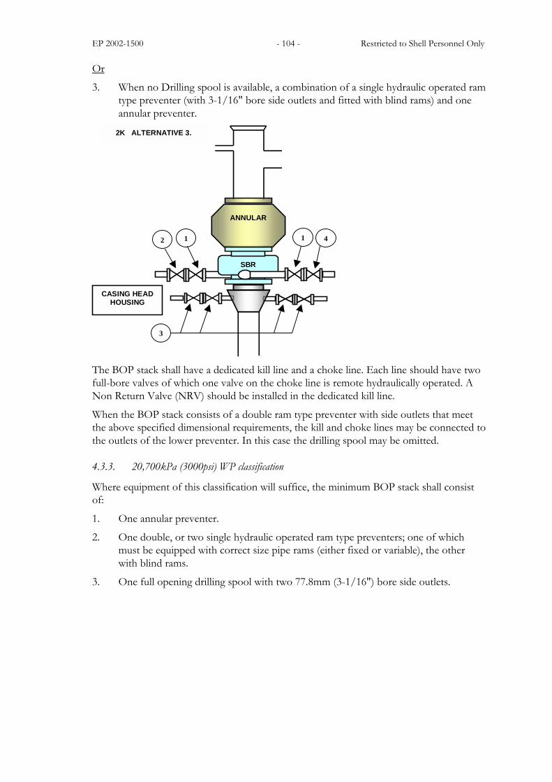
Or
3. When no Drilling spool is available, a combination of a single hydraulic operated ramtype preventer (with 3-1/16" bore side outlets and fitted with blind rams) and oneannular preventer.
3
CASING HEAD HOUSING
SBR
1 42 1
ANNULAR
2K ALTERNATIVE 3.
The BOP stack shall have a dedicated kill line and a choke line. Each line should have twofull-bore valves of which one valve on the choke line is remote hydraulically operated. ANon Return Valve (NRV) should be installed in the dedicated kill line.
When the BOP stack consists of a double ram type preventer with side outlets that meetthe above specified dimensional requirements, the kill and choke lines may be connected tothe outlets of the lower preventer. In this case the drilling spool may be omitted.
4.3.3. 20,700kPa (3000psi) WP classification
Where equipment of this classification will suffice, the minimum BOP stack shall consistof:
1. One annular preventer.
2. One double, or two single hydraulic operated ram type preventers; one of whichmust be equipped with correct size pipe rams (either fixed or variable), the otherwith blind rams.
3. One full opening drilling spool with two 77.8mm (3-1/16") bore side outlets.

EP 2002-1500 - 105 - Restricted to Shell Personnel Only
50.8mm (2") GATE VALVE3
76.2mm (3") HYDRAULICALLY OPERATED CHOKE LINE VALVE 2
76.2mm (3") GATE VALVE1
DRILLINGSPOOL
SBR
PR/VBR
3
1 42 1
CASING HEAD HOUSING
ANNULAR
3K WP MINIMUM REQUIREMENTS
NON-RETURN VALVE 4
The BOP stack shall have one dedicated kill line and a choke line. Each line should havetwo full-bore valves of which one valve on the choke line is remote hydraulically operated.A Non Return Valve (NRV) should be installed in the dedicated kill line.
When the lowermost ram type preventer has side outlets that meet the above-specifieddimensional requirements, the kill and choke lines may be connected to the outlets of thelower preventer. In this case the drilling spool may be omitted.
4.3.4. 34,500kPa (5000psi) WP classification
Where equipment of this classification will suffice, the minimum BOP stack shall consistof:
1. One annular preventer.
2. One double, or two single hydraulic operated ram type preventers; one of whichmust be equipped with correct size pipe rams (either fixed or variable), the otherwith shearing blind rams.
3. One full opening drilling spool with two 77.8mm (3 1/16") bore side outlets.

EP 2002-1500 - 106 - Restricted to Shell Personnel Only
50.8mm (2") GATE VALVE3
76.2mm (3") HYDRAULICALLY OPERATED CHOKE/KILL LINE VALVE 2
76.2mm (3") GATE VALVE1
SBR
PR/VBR
ANNULAR
CASING HEAD HOUSING
3
CASING SPOOL
DRILLINGSPOOL
1 22 1
5K WP MINIMUM REQUIREMENT
The BOP stack should have two dual-purpose kill and choke lines. Each line should havetwo full-bore valves of which one valve of each line is remote hydraulically operated. Bothlines should be connected to the kill and choke line manifold (see Section 4.6.2).
When dual purpose kill and choke lines are not employed, the BOP stack shall have onekill line and one choke line. Each line should have two full-bore valves of which one valveof each line is remote hydraulically operated. A Non Return Valve (NRV) should beinstalled in the dedicated kill line.
When the lowermost ram type preventer has side outlets that meet the above-specifieddimensional requirements, the kill and choke lines may be connected to the outlets of thelower preventer. In this case the drilling spool may be omitted.

EP 2002-1500 - 107 - Restricted to Shell Personnel Only
50.8mm (2") GATE VALVE3
76.2mm (3") HYDRAULICALLY OPERATED CHOKE/KILL LINE VALVE 2
76.2mm (3") GATE VALVE1
SBR
PR/VBR
ANNULAR
CASING HEAD HOUSING
3
CASING SPOOL
DRILLINGSPOOL
1 22 1
PR/VBR
4.3.5. 69,000kPa (10,000psi) WP classification
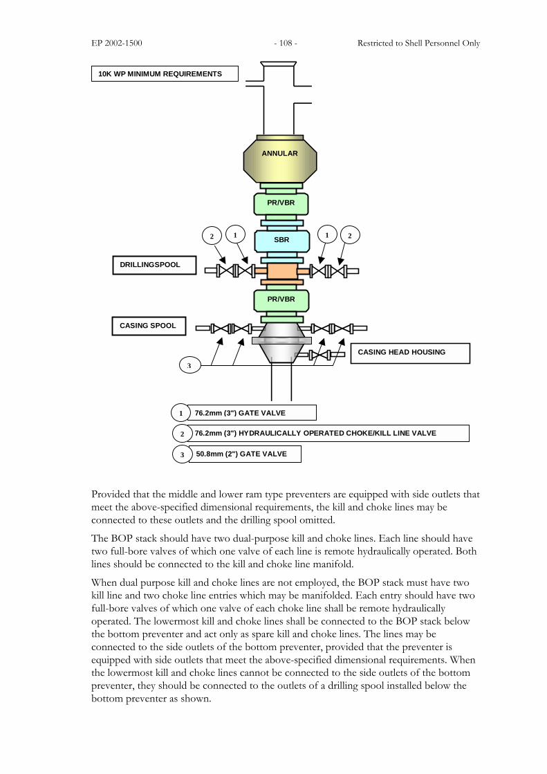
Where equipment of this classification is required, the minimum BOP stack shall consistof:
1. One annular preventer with a working pressure of 69,000kPa (10,000psi). (A34,500kPa (5000psi) WP annular preventer on a 69,000kPa (10,000psi) WP BOPstack is acceptable on existing stacks.)
2. Three single, or one double and one single, hydraulic operated ram type preventers;one of which must be equipped with shearing blind rams and the other two withcorrect size pipe rams. Variable Bore Rams (VBRs) may be used instead of one ofthe fixed pipe rams.
3. One full opening drilling spool with two 77.8mm (3 1/16") bore side outlets.
EP 2002-1500 - 108 - Restricted to Shell Personnel Only
50.8mm (2") GATE VALVE 3
76.2mm (3") HYDRAULICALLY OPERATED CHOKE/KILL LINE VALVE 2
76.2mm (3") GATE VALVE1
SBR
PR/VBR
ANNULAR
CASING HEAD HOUSING
3
CASING SPOOL
DRILLINGSPOOL
1 22 1
PR/VBR
10K WP MINIMUM REQUIREMENTS
Provided that the middle and lower ram type preventers are equipped with side outlets thatmeet the above-specified dimensional requirements, the kill and choke lines may beconnected to these outlets and the drilling spool omitted.
The BOP stack should have two dual-purpose kill and choke lines. Each line should havetwo full-bore valves of which one valve of each line is remote hydraulically operated. Bothlines should be connected to the kill and choke line manifold.
When dual purpose kill and choke lines are not employed, the BOP stack must have twokill line and two choke line entries which may be manifolded. Each entry should have twofull-bore valves of which one valve of each choke line shall be remote hydraulicallyoperated. The lowermost kill and choke lines shall be connected to the BOP stack belowthe bottom preventer and act only as spare kill and choke lines. The lines may beconnected to the side outlets of the bottom preventer, provided that the preventer isequipped with side outlets that meet the above-specified dimensional requirements. Whenthe lowermost kill and choke lines cannot be connected to the side outlets of the bottompreventer, they should be connected to the outlets of a drilling spool installed below thebottom preventer as shown.

EP 2002-1500 - 109 - Restricted to Shell Personnel Only
4.3.6. 103,500kPa (15,000psi) WP classification
Where equipment of this classification is required, the minimum BOP stack shall consistof:
1. One annular preventer with a working pressure of 103,500kPa (15,000psi) or a69,000kPa (10,000psi) WP unit, preferably with a body rated to 103,500kPa (15,000psi).
2. A four-ram stack is preferable. However, minimum requirements are three single, orone double and one single, hydraulic operated ram type preventers, one of whichmust be equipped with shearing blind rams and the other two with the correct sizepipe rams. Variable Bore Rams (VBRs) may be used instead of fixed pipe rams, butat least one ram type preventer shall be equipped with fixed pipe rams.
3. One full opening drilling spool with two 77.8mm (3-1/16") bore side outlets.
Provided that the middle ram type preventer is equipped with side outlets that meet theabove-specified dimensional requirements, the kill and choke lines may be connected tothese outlets and the drilling spool omitted. The 15K BOP stack configuration of thethree-ram-cavity stack is the same as the 10K stack. The configuration of the four-ram-cavity BOP stack is shown below.
CASING HEAD HOUSING
CASING SPOOL
SBR
2 1
1 2
ANNULAR
50.8mm (2") GATE VALVE 3
76.2mm (3") HYDRAULICALLY OPERATED CHOKE/KILL LINE VALVE 2
76.2mm (3") GATE VALVE1
PR/VBR
PR/VBR
PR
15K WP FOUR-RAM-CAVITY BOP
DRILLINGSPOOL
1 22 1

EP 2002-1500 - 110 - Restricted to Shell Personnel Only
The BOP stack should have two dual-purpose kill and choke lines. Each line should havetwo full-bore valves of which one valve of each line is remote hydraulically operated. Bothlines should be connected to the kill and choke line manifold.
When dual purpose kill and choke lines are not employed, the BOP stack must have twokill line and two choke line entries which may be manifolded. Each entry should have twofull-bore valves of which one valve of each choke line shall be remote hydraulicallyoperated. The lowermost kill and choke lines shall be connected to the BOP stack belowthe bottom ram preventer and act only as spare kill and choke lines. The lines may beconnected to the side outlets of the bottom preventer, provided that the preventer isequipped with side outlets that meet the above-specified dimensional requirements. Whenthe lower kill and choke lines cannot be connected to the side outlets of the bottompreventer, they must be connected to the outlets of a drilling spool installed below thebottom preventer as shown.
4.4. Blow Out Preventer Equipment Installation
A BOP will only act as a functional pressure containment device if properly installed andhooked up. This section comprises a list of critical issues to be addressed or guidelines tobe applied during rig-up.
The BOP equipment installation shall conform to the following:
1. Wellhead equipment should be designed to withstand anticipated pressures and allowfor future remedial operations.
2. Ram type preventers must always be installed the correct way up, as in most casesthe seal is �pressure assist� and will only hold pressure in one direction.
3. All connections, valves, fittings, piping, etc., subject to well pressure, must beflanged, clamped or welded and have a minimum working pressure equal to the ratedworking pressure of the preventers. Screwed valves and fittings are only acceptableon installations up to 13,800kPa (2000psi) WP.
4. Valves must be of the flush through-bore type when in the open position.
5. When installed, all ring gaskets should be new, checked for cleanliness and coatedwith light oil. Dry and/or previously used ring gaskets should never be installed.
6. All correct size bolts/nuts and fittings shall be in place and tight. All connectionsshall be pressure tested before drilling is resumed. The use of a torque device formaking up bolted connections is recommended.
7. The ID of the bell nipple should be large enough for hanger and seal assemblies topass through. Slip and seal assemblies should preferably be landed through the BOPsbefore lifting the BOP stack. Emergency slip and seal assemblies for mandrel typewellheads can rarely be installed without lifting the BOP stack. When lifting the stackis necessary is shall only be done after the cement seal has adequate integrity and thewell cannot flow.
8. When non-fluted boll-weevil hangers are used to land the casing string beforecementing, wellhead side outlets shall have a bore, large enough to avoid excessiveannular backpressure whilst cementing. A hydraulically operated valve should beinstalled in both side outlets to allow closing in the well in an emergency.

EP 2002-1500 - 111 - Restricted to Shell Personnel Only
9. Fluted hangers are recommended so as to avoid bypassing the wellhead/BOP stackduring cementing operations.
10. All manually operated valves should be equipped with hand wheels, and be ready forimmediate use, including the valves on the wellhead.
11. Ram preventer hand wheels are not a general requirement. The locking screwsshould be operated each time the preventers are tested to ensure that they turnfreely. Rams should be locked whenever used for secondary control.
12. BOP equipment shall be function tested and pressure tested, when installed, and atthe appropriate times during operations to determine that the system will functionproperly. (See Section 4.8)
13. The Company drilling representative shall inspect and approve every BOPinstallation after flanging up and testing. He/she or an authorised delegate shallwitness every BOP pressure test.
14. Circulating access to the well bore (or annulus) should always be possible, henceprovision must be made for connection of one kill/choke line below the lower-mostpreventer.
15. Wellhead side outlets shall not be used for killing purposes, except in case ofemergency. In an emergency situation, the kill line may be connected to the sideoutlet of the casing spool when circulating access to the well bore is required. Thecasing spool outlet should have the proper connection to allow changing over thepermanent kill line.
16. Kill lines shall not be used for routine fill-up operations.
17. When critical operations are being carried out on high-pressure wells, a second killline should be employed and tied into the kill line near the BOP stack. A high-pressure pump should be lined up to this kill line.
18. All pipelines shall be securely anchored and fitted with snub lines across theconnections.
19. Choke lines shall be as straight as practicable and firmly anchored to preventexcessive whip or vibration. Turns, if required, should be targeted. Flexible kill andchoke hoses, longer than 4m (12ft), shall be supported and anchored in accordancewith manufacturer's recommendations. The distance between anchoring points shallbe 4m (12ft) or less.
20. Ensure that the manufacturer's BOP operating manual is followed and no alterationsare made to the BOP equipment without written consent from the manufacturer. Re-certification may be required after making equipment alterations.
21. The primary kill and choke lines of a three-ram-cavity BOP stack should beconnected between the lower pipe and the shearing blind rams. i.e. between thelower two cavities.
22. The primary kill and choke lines of a two-ram-cavity BOP stack should be connectedbelow the lowermost ram preventer.
23. Multiple choke lines should be connected to a kill and choke line manifold. Thereshould be only one line from the kill and choke line manifold to the choke manifold.

EP 2002-1500 - 112 - Restricted to Shell Personnel Only
4.5. Control System Requirements for Surface Bop Stacks
The specifications and hook-up of the control system are critical to the safe and effectiveoperation of the stack. This section defines the minimum equipment requirements andspecification.
Control systems for surface BOP stacks shall consist of the following as a minimum:
1. One independent automatic accumulator unit rated for 20,700kPa (3000psi) WP witha control manifold, clearly showing 'open' and 'closed' positions for preventer(s) andthe remote hydraulic operated kill and choke line valves.
• It is essential that all air and hydraulic BOP operating units be equipped with0-20,700kPa (0-3000 psi) regulator valves similar to the Koomey type TR-5which will not 'fail open', causing complete loss of operating pressure.
• Without recharging, the accumulator capacity shall be adequate for closing andopening all preventers and closing again the annular preventer and one ramtype preventer, and holding them closed against wellbore pressure equal to therated working pressure of the preventers.
• Accumulator units must be provided with electrically and air-driven highpressure pumps which automatically charge the accumulator bottles to the pre-set pressure. The electric pump should be fitted with an electric pressureswitch, which automatically stops the electric pump when the accumulatorpressure reaches 20,700kPa (3,000psi) and starts the pump again when thepressure drops to 18,970kPa (2,700psi) or below. The air-driven pump shouldbe fitted with an air pressure switch, which automatically stops the air-drivenpump when the manifold pressure reaches 20,700kPa (3,000psi) and starts thepump again when the pressure drops to 18,620kPa (2,700psi) or below
• A backup power supply should be available to maintain accumulator pressurein case of failure of the primary power source.
• In addition to the energy stored in the accumulator for emergency closing ofpreventers, a backup storage system independent of rig power could also bemade available equal in capacity to accumulator needs (when a hydraulicsystem is mandatory).
Note: High pressure bottled nitrogen provides a practical and inexpensive backupsystem. A standard nitrogen bottle contains 1.53 cu. ft. or 11.5 gallons of nitrogen at2,200 psi. If this is allowed to expand to 1,200 psi, there is a volume increase of 9.5gallons. Thus, the same volume requirements set for the accumulator can be set forthe bottled nitrogen backup system, and a relatively small number of bottlesmanifolded together will provide the needed capacity. The piping should be arrangedso that the nitrogen can be routed through a pressure regulator directly to the BOPstack, bypassing the accumulator, and, optionally, also be piped to operate theclosing unit pumps if desired. (See Figure 5.A.4 in API RP 53.)
• The unit shall be located in a safe area away from the drill floor.
• Control lines shall be protected from damage.
• It shall include a low pressure warning alarm and hydraulic fluid level indicatoror low fluid level warning alarm.

EP 2002-1500 - 113 - Restricted to Shell Personnel Only
2. All BOP stack installations should have two graphic remote control panels, each oneclearly showing 'open' and 'closed' positions for each preventer and the hydraulicoperated choke line valves.
• Each of these panels should include a master shut-off valve and ideally, thoughmandatory, controls for regulator valves and for a bypass valve.
• One panel must be located near the Driller's position, the other panel to belocated near the exit of the location or near the Toolpusher�s office.
3. Control hoses that are high-pressure and fire-resistant with a working pressure of20,700kPa (3000psi) are preferred, although steel swivel joints are acceptable. Thehoses should be steel wrapped (co-flex type) to provide greater resistance to fire andimproved durability.
4. All master and remote operating panel handles are to be free to move into eitherposition at all times, i.e. the shear ram operating handles should not be locked (butshould be protected from inadvertent operation).
5. All spare operating lines and connections, which are not used in the system, are to beproperly blocked off.
4.6. Mud-Gas Separator
Mud-Gas Separators are a vital component of the well kill system. Their specification andinstallation is crucial to their safe use during well control operations. This sectioncomprises guidelines to their selection and evaluation.
4.6.1. Overview
Mud-Gas Separators (MGS) (or atmospheric degasser or poor-boy degasser) have been inuse for many years with little change in fundamental design.
They can be described as a passive type cascade/baffle gas knock-out unit. They operate atatmospheric pressure or slightly above (atmospheric plus vent line backpressure). Theirfunction is to remove free gas from the contaminated mud leaving the choke manifold butequally important to remove mud/liquid droplets from liberated gas prior to entering thevent line. (Entrained gas is extracted at the vacuum degasser).
The capacity of the MGS is dependent on the design. If the capacity is exceeded, liquidmud or oil droplets may be carried up through the vent line. More importantly, gas mayblow straight through the U-tube (Seal leg) and into the shale-shaker house, where theremay be potential for explosion and fire.
It is critical therefore that the mud-gas separator specifications must be fully evaluated. Inshort:
• For new rig contracts, the minimum required mud gas separator specifications must becalculated and stated in detail on tender documents.
• For existing rig contracts, the mud gas separator specification must be evaluated as partof the well design process.
• Instrumentation and alarm mechanisms must be in place, such that if the capacity ofthe MGS is approached, actions can be taken to reduce the gas rate, or the flow fromthe well diverted to by-pass the MGS. On a land rig, this would be to a flare and on anoffshore rig to an overboard line.

EP 2002-1500 - 114 - Restricted to Shell Personnel Only
• High gas rates will typically be associated with high kick volumes. These high gas ratesmay also result from gas dissolved in OBM arriving at a wide-open choke.
4.6.2. Evaluation Process
A methodology for evaluating the capacity of mud gas separators was developed by J.M.Prieur of Shell Expro in 1990 and can still be used today. It is very complex to calculate gasrates � it is only really feasible to do this using one of the realistic kick simulators. As statedpreviously, it is essential that the appropriate pressure gauges and alarms are installed onthe MGS to warn personnel when the gas rate is approaching the capacity of the MGS.This section introduces the main steps in the evaluation sequence.
Separation CapacityThis is based on the minimum droplet size that will settle out of a moving gas stream. Themaximum allowable gas velocity is calculated using the density of the liquid and gas phases.
Blow Down CapacityA U-tube between the bottom of the separator vessel and the header tank forms a liquidseal preventing gas escape to the shaker house. Blow down is where the pressure in theseparator vessel caused by back-pressure from gas in the vent line exceeds the hydrostatichead of the liquid seal.
Gas Handling CapacitySeparation is a function of the separator vessel dimensions, while blow down capacity is afunction of the vent line. The gas handling capacity is the lower of the two.
Flow Rate and Kill RateThe gas handling capacity is used to ensure that the flow rate during a kill operation ismaintained within the safe operating range of the separator. This information is presentedas a graph showing the safe operating envelope.

EP 2002-1500 - 115 - Restricted to Shell Personnel Only
4.6.3. System Schematic
Key
P
∆
P
T
Pressure Gauge
Differential Pressure Meter
Pressure Sensor
Temperature Sensor
Valve
P
Drilling Choke
Manifold
From Mud Pumps
From CementPumps
Over Board
Choke Line
Kill Line
To Burner Booms
Fill-Up and Flushing Line
To Shale Shakers
Liquid Seal Tank
Liquid Seal Depth
T
PP
∆
Atmospheric Mud/Gas Separator
Ventline Up Derrick
Secondary Ventline
Drain
4.6.4. Detailed Evaluation
A computer program (created by Expro Group Integrated Services Aberdeen) for theevaluation of existing separators and the calculation of parameters required for tendering isavailable on the Wells Global Network, Forum 24 - Well Control, well control informationNo.9. Mud Gas seperator evaluation program
This program will:• Calculate the gas throughput capacity of an existing system in mmscf/d• Calculate the required gas throughput capacity in mmscf/d for a future well

EP 2002-1500 - 116 - Restricted to Shell Personnel Only
4.6.5. Other Considerations
Design TemperatureVery low temperatures can be achieved down stream of the choke due to gas expansion. Itis very difficult to calculate what temperatures will be reached under these dynamicconditions, however it is generally accepted within Shell that minus 45°°°° Celsius isacceptable
Pressure RatingDuring normal operations the vessel should not be submitted to any pressure in excess ofthe liquid seal hydrostatic head. However, if the seal line plugs the vessel could fill up tothe top of the vent line with mud.
The pressure vessel should therefore be able to withstand the pressure imposed by thismud column. As most vent lines are 40-55m (130 � 180 ft) in height, a pressure rating of1000 kPa (150psi) will be fit for purpose
4.6.6. Instrumentation
(Minimum equipment standards, maintenance, combined gauges, testing)
• A low pressure 100kPa (15psi) gauge shall be fitted to the base of the line from thechoke manifold. The gauge reading should be easily visible.
4.6.7. Rig-Up and Operation
The following shall be met when configuring (or specifying the configuration of) the pipework for the mud-gas separator:
There must be an injection point down stream of the choke to allow the use of glycol toinhibit hydrate formation
• There are to be no valves, pipe expansion or constrictions within 3m (10ft) of theinlet nozzle;
• If a bend is required in the feed pipe it shall be long sweep and in a vertical planethrough the axis of the feed nozzle;
• The pipe reducer of the gas outlet line should be no nearer to the top of the vesselthan 0.6m (2ft).
• The gas outlet line shall be a minimum of 200mm (8") diameter. If the vent existsmore than 40m (130ft) from the vessel this vent line diameter should be increased toensure that the back pressure in the vent line does not exceed 15kPa (2psi), at a gasflow rate of 0.2 x 10⁶m3(st)/d (7MMscf/d).
• No reduction in any vessel dimension is permitted.
• Internal mist mats are not permitted due to their unsuitability for the rugged service.
• The mud-gas separator shall have one or more vent lines leading a safe distancedownwind from the well, and/or to the top of the derrick. Low places in the ventlines should be avoided to prevent accumulation of liquids.
• Never connect the choke manifold and/or mud-gas separator discharge lines directlyto the degasser (always have an open pipe).
EP 2002-1500 - 117 - Restricted to Shell Personnel Only
• The mud-gas separator shall not be operated above its manufacturers designlimitations as calculated. Operating outside of this envelope will give poor mud/gasseparation and the possibility of gas blow through. An additional unit with dedicatedvent line shall be installed when the mud-gas separator capacity is insufficient for thewell to be drilled.
There must always be provision to divert flow from the choke manifold direct to the flarepit.
4.6.8. Common Industry Designs.
There are a number of mud-gas separators in current use, all working on the sameprincipals.
The mud-gas separator can be installed as:
• A skid mounted horizontal unit outside a mud tank;
• Vertical unit outside a mud tank;
• Unitized with the trip tank;
The Shell philosophy on mud gas separator design has been captured in WEST andincludes a review of all makes and models in common use. This information is available inthe Shell intranet.
More recently, Smedvig Technology AS in association with Shell Expro have produced anupdated design which incorporates the latest legislation and regulatory guidelines. Fullspecification is available on the Shell intranet.
4.7. Other Well Control Equipment
In addition to the Blow Out Preventer, there are other items of equipment which arerequired to either contain or control flow from the well.
4.7.1. Diverter Equipment
The diverter is installed on top of the wellhead to enable flow from shallow formations tobe diverted away from the work area in case of a shallow gas kick. However, currentdiverter equipment is not yet designed to withstand an erosive shallow gas kick for aprolonged period. The diverter system is still seen as a means of "buying time" to evacuatethe drilling site.
In principle, a diverter system must be installed on each well when both of the followingconditions apply:
1. There is a possibility of losing primary well control, which may result in a kicksituation.
2. The well cannot be closed-in with a BOP stack, because the formation below thestove pipe/marine conductor, conductor string, or surface string is too weak.Fracturing of the formation will occur if the well is closed-in.
See also "Shallow Gas Procedures Guidance Manual", report EP 88-1000.Plus Section 5.3 of this manual
Mei I Choate
EP 2002-1500 - 118 - Restricted to Shell Personnel Only
Diverter Equipment SpecificationsFlow restrictions in diverter systems should be avoided where possible, because they maylead to formation breakdown and cratering of the well in case of a shallow gas blowout.
The minimum required nominal ID of diverter outlets/lines is considered to be 304.8mm(12").
In principle two outlets are required on the diverter spool. They should face oppositedirections to be able to vent flow downwind of the rig. However, one outlet only may beconsidered in the case where there is a prevailing wind direction, and the vent line extendsa sufficient distance from the rig to permit safe venting. Diverter lines should be as short aspossible, but long enough to conduct flow past the extremity of the offshore drillingstructure, or away from any obstacle in land operations. Rig structure and/or cellar designmay have to be modified to accommodate straight diverter lines.
The minimum rated working pressure of diverter equipment is based on the anticipatedbackpressure during a shallow gas blowout and therefore largely depends on the size of thediverter lines. The minimum rated working pressure of the recommended large borediverter line system should be 3450kPa (500psi) WP. Dynamic forces are much higher inthe initial stage of diverting a well, when the expanding gas is forcing the mud out of thediverter system.
The following considerations should be made when selecting diverter equipment:
1. The equipment shall be selected to withstand the maximum anticipated surfacepressures.
2. Welded flange or hub connections are mandatory on diverter systems; quickconnections in diverter lines are not allowed.
3. Diverter lines should be straight and properly anchored. (especially at the end of thelines).
4. Diverter lines should be sloping down towards the outlet so as to be self-draining,and to avoid blockage of the lines with cuttings, etc.
5. Installation requirements for wellhead and BOP equipment also apply to diverterequipment. (See Section 4.4)
6. A diverter system can be a BOP stack system with a diverter spool, or a specificallydesigned and developed diverter system. The faster closing diverter unit is preferredto a large and slowly closing annular preventer. In any case, the diverter lines andmud return lines should be separate, not partially integrated lines. This is necessary toavoid gas entering the rig system in case the separating valve between both lines failsto seal.
7. Diverter valves shall be full opening valves with an actuator (pneumatic or hydraulic).The bore of the diverter valves shall be equal to the bore of the diverter lines.
8. Each diverter system should incorporate a kill line facility (including a check valve) tobe able to pressure and function test the system and to be able to pump waterthrough the diverter system.
9. The diverter control system should preferably be self-contained or may be an integralpart of the BOP accumulator unit and control system. It shall be located in a safearea away from the drilling floor and have the control functions clearly identified.

EP 2002-1500 - 119 - Restricted to Shell Personnel Only
10. The diverter control system should be capable of operating the diverter system fromtwo or more locations, one to be located near the Driller's position. It should containthe minimum of functions. Preferably, a one-button or lever-activated functionshould operate the entire diverter system.
11. A 1-1/2" hydraulic operating line should be used for diverter systems with a 1-1/2"NPT closing chamber port size. The hydraulic line for the opening chamber portmay be 1".
12. All spare operating lines of the control system, and connections which are not usedshould be properly plugged off.
13. Control systems of diverters/annular preventers and BOPs should be capable ofclosing the diverter and annular preventers smaller than 508mm (20") within 30seconds, and annular preventers of 508mm (20") or larger within 45 seconds.
14. Diverter valves should be opened before the diverter element is completely closed.
15. It should be possible to control pumping operations at the pumps as well as on thedrilling floor.
P Valve: Pressure Operated, R tControlled Failsafe O
Actuator
P
Valve Diverter
Line
SURFACE DIVERTER INSTALLED ON STOVE PIPE OR MARINE CONDUCTOR
26” or 30”
Stove Pipe /Marine
Conductor
29 ½”Bag TypePreventer
Kill Line NRV
Actuator
P
Valve
P
Diverter Line
Diverter Spool
Figure 4.7.1: Surface Diverter on Stove Pipe � Kill line on diverter spool

EP 2002-1500 - 120 - Restricted to Shell Personnel Only
Kill Line NRV
P Valve Diverter Line
P Valve
Diverter Line
20”Bag TypePreventer
26” or 30”Stove Pipe /
MarineConductor
SURFACE DIVERTER INSTALLED ON STOVE PIPE OR MARINE CONDUCTOR
P Valve Diverter Line
Actuator
P Valve
Diverter Line
Actuator
Kill Line
NRV P
Choke Line
20”Bag TypePreventer
26” or 30”Stove Pipe /
MarineConductor
Blind / Shear Rams
Option B
P
P
Option A
P Value: Pressure Operated, Remote Controlled Failsafe Open
ActuatorActuator
Diverter Spool
DiverterSpool
Figure 4.7.2: Surface Diverter on Stove Pipe � Kill line on wellhead or single ram.

EP 2002-1500 - 121 - Restricted to Shell Personnel Only
SURFACE DIVERTER INSTALLED ON STOVE PIPE OR MARINE CONDUCTOR
P Valve: Pressure Operated, Remote Controlled Failsafe Open
Option C
ActuatorActuator
P
Choke Line Kill Line
NRV
P
Casing Housing Conductor String
20”Bag Type Preventer
P Valve Diverter Line
P Valve
DiverterLine
Pipe Rams
26” or 30”Stove Pipe /
MarineConductor
Blind / ShearRams
Diverter Spool
Figure 4.7.3: Surface Diverter on Stove Pipe � Kill line below dual ram.
4.7.2. Choke Manifold and Kill & Choke Line Manifold
1. The manifolds shall be constructed in accordance with Figure 4.7.1 and Figure 4.7.2which is the minimum requirement for all working pressure ratings over 13,800kPa(2000psi). Alternatively, a choke manifold as already installed by the owner of thedrilling unit may be acceptable, but only if approved in writing by the Company RigSuperintendent.
2. Whilst drilling, the block valves upstream of both chokes and valves downstream ofthe remote choke to the mud-gas separator shall be in an open position.
3. The remotely adjustable choke, the manually operated adjustable choke and all valvesat the choke manifold shall be left in a position (closed or open) to facilitate closingin by the hard or soft shut-in method, as agreed to be appropriate.
4. The remote choke is to be operated from a control panel installed near the Driller'sposition.
5. The minimum recommended size for all choke lines and valves is 76.2mm (3")through bore. Valve size and line bore size of BOP stack side outlets and valves,choke lines and choke manifold should be identical throughout the system.

EP 2002-1500 - 122 - Restricted to Shell Personnel Only
6. Choke manifolds rated to 103,500kPa (15,000psi) shall have hydraulically operatedvalves upstream of any choke to assist in opening/closing valves under pressurequickly, thus minimising gate and seat wear.
7. Chokes should incorporate a suitable bleeder valve facility to ensure that the pressurecan be released prior to removal of the bonnet nut. Hammer type threaded bonnetnuts are not recommended. Flanged or bonnet clamp connections are preferred.
8. Temperatures downstream of the choke are to be limited to the design temperaturerating of the choke manifold.

EP 2002-1500 - 123 - Restricted to Shell Personnel Only
Figure 4.7.4: Typical Back Pressure Manifold arrangement

EP 2002-1500 - 124 - Restricted to Shell Personnel Only
For Use With BOP-stack, Having A Rated Working Pressure Of:-
103,500kPa (15,000 psi) 69,000 kPa (10,000 psi)34,500 kPa (5,000 psi)20,700 kPa (3,000 psi)13,800 kPa (2,000 psi)
ItemNo. Qty. Description
kPa psi kPa psi kPa psi1 1 Studded cross
76.2 x 76.2 x 76.2 x 76.2 x 50.8mm (3� x 3� x 3� x 3� x 2�)103,500 15,000 69,000 10,000 34,500 5,000
2 1 50.8mm (2�) nominal size gate valve with steel seat 103,500 15,000 69,000 10,000 34,500 5,000
3 11 76.2mm (3�) nominal size gate valve with steel seat - - - - 34,500 5,0003 5 76.2mm (3�) nominal size gate valve with steel seat 103,500 15,000 69,000 10,000 - -
3a 6 76.2mm (3�) nominal size gate valve with steel seat (hydraulic remoteoperated valve)
103,500 15,000 69,000(optional)
10,000(optional)
- -
4 1 76.2mm (3�) nominal size manual adjustable choke 103,500 15,000 69,000 10,000 34,500 5,000
5 1 Hydraulic Remote operated choke 103,500 15,000 69,000 10,000 34,500 5,000
6 2 120.7mm OD x 76.2mm ID (41� OD x 3� ID) wear nipple 76.2mm flanges103,500
3� flanges15,000
76.2mmflanges 69,000
3� flanges10,000
76.2mmflanges34,500
3�flanges5,000
7 3 Studded cross76.2 x 76.2 x 76.2 x 76.2mm (3� x 3� x 3� x 3�)
103,500 15,000 69,000 10,000 34,500 5,000
8 2 Flange companion lead filled 76.2mm (3�) 103,500 15,000 69,000 10,000 34,500 5,0009 2 Martin-Decker Series GM6A pressure gauge or equivalent 103,500 15,000 69,000 10,000 41,500 6,000
10 1 Martin-Decker Sensor Series GM6A or equivalent 103,500 15,000 69,000 10,000 41,500 6,000
11 1 Y-piece: 76.2 x 76.2 x 76.2mm (3� x 3� x 3�) 103,500 15,000 69,000 10,000 34,500 5,000
12 4 76.2mm (3�) Nominal size gate valve with steel seat 103,500 15,000 69,000 10,000 34,500 5,000
13 1 Check valve 77.79mm �103,500
3 1/6� �15,000
77-79mm� 69,000
3 1/6� �10,000
79.38mm �34,500
3 1/8� �5,000
14 4 50.8mm (2�) Nominal size gate valve with steel seat 103,500 15,000 69,000 10,000 34,500 5,000
Figure 4.7.5: Back Pressure manifold � component rating

EP 2002-1500 - 125 - Restricted to Shell Personnel Only
4.8. Tests for Surface Wellheads and Bop Equipment
Testing requirements are given for the following equipment:1. Blowout preventers, wellhead components and their connections.2. The BOP operating unit.3. The choke manifold, valves, kill and choke lines and valves on the side outlets of the
casing spool.4. The kelly or top drive and kelly cocks stab in valves etc..
4.8.1. Blowout Preventers, Wellhead Components And Their Connections
Function TestsShould be carried out on BOP hydraulic operated components when they are installed andweekly thereafter.
Function tests should be performed with reduced operating pressure to avoid unnecessarywear and tear, particularly when there is no drill string in the hole.
Pressure TestsTestson the blowout preventers, wellhead components and their connections should, oninitial installation, be made with fresh water. Subsequent tests should also be with water.However, in circumstances where this is not practical, dispensation may be allowed fortesting with the drilling fluid in the hole. Any such dispensation must be clearly indicated inthe Drilling Programme.
The following test tools may be used:
1. Plug Type Tester and test sub (PTT).
2. Combination Cup Type Tester/hang-off tool (CCTT).
3. Cup Type Tester (CTT).
The PTT or CCTT is run on drill pipe and landed in the wellhead whilst the CTT issuspended on drill pipe. Test tool design, application, and testing procedures depend onthe type and the design of the wellhead.
After any flanging up operation, the wellhead and each item of the BOP equipment shouldbe high pressure tested to the rated working pressure of the wellhead or the blowoutpreventers, whichever is the lower, and to a low pressure of 3450 kPa (500 psi). When aCTT is used and it is seated in the casing, test pressure must not exceed 85% of casingburst rating. Wellhead side outlets below the PTT must be open during a test to avoid therisk of pressure increase below the test tool if there is a leak.
During subsequent drilling operations, the equipment should be pressure tested at regularintervals. The frequency of tests will, as a minimum, comply with Company and/orgovernment regulations and generally should be done:
• After installation of any new wellhead component and BOP assembly and prior todrilling.
• Every fortnight, or other interval (maximum 3 weeks), depending on type ofoperation.
• Prior to a production test.
EP 2002-1500 - 126 - Restricted to Shell Personnel Only
• At any time requested by the Company drilling representative.
Subsequent tests of the wellhead and preventers should be to the anticipated maximumwellhead pressure with a maximum limit for the annular preventer of 70% of its ratedworking pressure.
The CTT must be run with open-ended drill pipe to prevent pressurisation of thecasing/hole below the cup in the event that it leaks. The drill pipe shall also be strongenough to withstand the tensile load caused by the hydraulic pressure on the cup area. Theassembly should be suspended in the elevators, not set in the slips. Hook load must bemonitored and care must be taken not to overload the derrick or hoisting equipment.
Blind/shear rams shall be tested with the PTT converted into a blind plug. During this testthe wellhead side outlets below the tester shall be open to prevent pressurising the casing.The wellhead side outlets must be monitored at all times, and closed immediately oncompletion of the testing.
Casing rams should be visually inspected prior to installation. Casing rams and BOPbonnets should be pressure tested after installation with a Casing Ram Tester/CTTcombination tool, to the usual test pressure.
Plug and cup type testers, suitable for pressure testing the wellhead and BOP equipmentinstalled on all casing strings, shall be available. Retrievable packers with large slip areasmay also be used.
NOTE: It should always be possible to close in the well or any annulus immediately, ifflow is observed from the well or annulus while testing is in progress. Annular valvesopened during pressure testing or any other type of operation shall not be left openunattended.
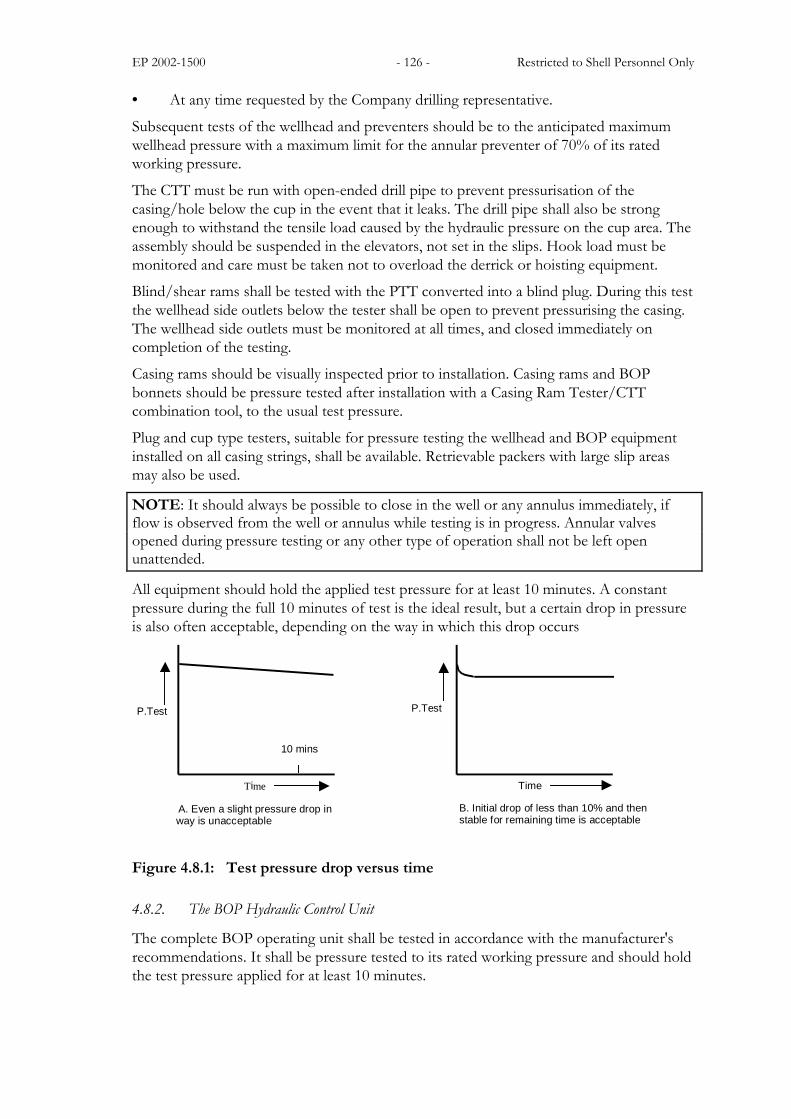
All equipment should hold the applied test pressure for at least 10 minutes. A constantpressure during the full 10 minutes of test is the ideal result, but a certain drop in pressureis also often acceptable, depending on the way in which this drop occurs
10 mins
Time A. Even a slight pressure drop in way is unacceptable
P.Test
Time
B. Initial drop of less than 10% and then stable for remaining time is acceptable
P.Test
Figure 4.8.1: Test pressure drop versus time
4.8.2. The BOP Hydraulic Control Unit
The complete BOP operating unit shall be tested in accordance with the manufacturer'srecommendations. It shall be pressure tested to its rated working pressure and should holdthe test pressure applied for at least 10 minutes.
EP 2002-1500 - 127 - Restricted to Shell Personnel Only
The tests shall also confirm that all BOP controls:
• are properly connected;
• activate the functions indicated on them;
• perform as per specification.
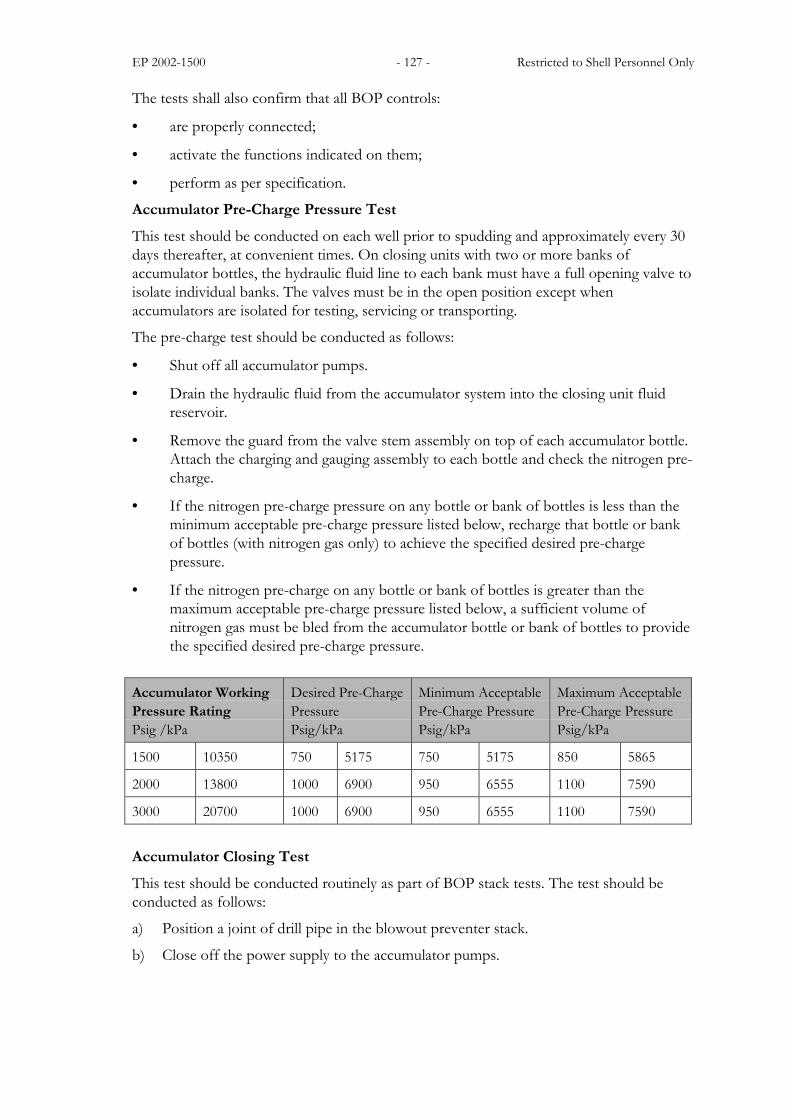
Accumulator Pre-Charge Pressure TestThis test should be conducted on each well prior to spudding and approximately every 30days thereafter, at convenient times. On closing units with two or more banks ofaccumulator bottles, the hydraulic fluid line to each bank must have a full opening valve toisolate individual banks. The valves must be in the open position except whenaccumulators are isolated for testing, servicing or transporting.
The pre-charge test should be conducted as follows:
• Shut off all accumulator pumps.
• Drain the hydraulic fluid from the accumulator system into the closing unit fluidreservoir.
• Remove the guard from the valve stem assembly on top of each accumulator bottle.Attach the charging and gauging assembly to each bottle and check the nitrogen pre-charge.
• If the nitrogen pre-charge pressure on any bottle or bank of bottles is less than theminimum acceptable pre-charge pressure listed below, recharge that bottle or bankof bottles (with nitrogen gas only) to achieve the specified desired pre-chargepressure.
• If the nitrogen pre-charge on any bottle or bank of bottles is greater than themaximum acceptable pre-charge pressure listed below, a sufficient volume ofnitrogen gas must be bled from the accumulator bottle or bank of bottles to providethe specified desired pre-charge pressure.
Accumulator WorkingPressure RatingPsig /kPa
Desired Pre-ChargePressurePsig/kPa
Minimum AcceptablePre-Charge PressurePsig/kPa
Maximum AcceptablePre-Charge PressurePsig/kPa
1500 10350 750 5175 750 5175 850 5865
2000 13800 1000 6900 950 6555 1100 7590
3000 20700 1000 6900 950 6555 1100 7590
Accumulator Closing TestThis test should be conducted routinely as part of BOP stack tests. The test should beconducted as follows:
a) Position a joint of drill pipe in the blowout preventer stack.
b) Close off the power supply to the accumulator pumps.

EP 2002-1500 - 128 - Restricted to Shell Personnel Only
c) Record the initial accumulator pressure.The pressure should be the design operating pressure of the accumulators.Adjust the regulator to provide 1500psi operating pressure to the annular preventer.
d) Operate the sequence of functions as relevant to the rig type.
For a Land Rig
• Close the annular preventer and one pipe ram (sized for the pipe in the stack).
• Open the HCR valve on the choke-line.
For the Floating Rig
• Close and open all the well control functions (apart from blind/shear rams).
• Simulate the operation of the blind/shear rams by operating another pipe ramtwice.
• After each function, record the volume used, the time taken and the residualaccumulator pressure. The residual accumulator pressure after completing all thetests must be at least 200psi greater than the precharge pressure.
e) Turn on the accumulator pumps.
• Having completed the tests, recharge the accumulator system to its designedoperating pressure. Record the time taken to recharge the system.
Closing Unit TestPrior to conducting any tests, the closing unit reservoir should be inspected to be sure itdoes not contain any foreign fluid or debris. The closing unit pump capability test shouldbe conducted routinely as part of BOP stack tests. This test can be conveniently scheduledeither immediately before or after the accumulator closing time test. The test should beconducted according to the following procedure:
a) Position a joint of drill-pipe in the blow-out preventer stack.
b) Isolate the accumulators from the closing unit manifold by closing the required valves.
c) If the accumulator pumps are powered by air, isolate the rig air system from thepumps.
• A separate closing unit air storage tank should be used to power the pumps duringthis test. When a dual power (air and electric) source system is used, both powersupplies should be tested separately.
d) Close the annular preventer and open one choke-line failsafe valve (or HCR valve).
• Record the time (in seconds) required for the closing unit pumps to close theannular preventer.
• Record remaining pressure in the accumulator manifold. Pressure should not beless than 200 psi over the pre-charge perssure.
e) Close the choke-line failsafe (or HCR valve) and open the annular preventer.
• Open the accumulator system to the closing unit and charge the accumulatorsystem to its designed operating pressure using the pumps.

EP 2002-1500 - 129 - Restricted to Shell Personnel Only
4.8.3. The Choke Manifold, Valves, Kill-&-Choke Lines And Valves On The Side Outlets
The choke manifold, valves, kill, choke lines and valves on the side outlets shall be pressuretested with water whenever feasible. The initial test should be to the rated working pressureof the ram type preventers or the rated working pressure of the manifold, whichever is thelower. Subsequent tests may be limited to the BOP test pressure. The equipment shouldhold the test pressure applied for at least 10 minutes. All lines should be flushed prior totesting to ensure they are not blocked and all air is removed from the lines.
A pressure test schedule should be drawn up to ensure that all components are testedcorrectly and in the most efficient manner.
No tests shall be performed against closed chokes.
4.8.4. The Kelly Or Top Drive Kelly Stop-cocks And Stab-in Valves
The kelly or top drive and kelly cocks shall be pressure tested to their rated workingpressure with a test sub. The equipment shall hold the applied test pressure for at least 10minutes.
4.9. Maintenance and Inspection of Surface Well Control Equipment
The general recommendations on maintenance, inspection and testing of BOP andassociated equipment are presented in this section.
4.9.1. The Blow Out Preventer
• A BOP body pressure test shall be carried out once a year on the test stump atsurface, in accordance with the manufacturer's specification for such a test.
• BOP's shall undergo a regular major overhaul and inspection, depending on the typeof work and period in use. Periods between checks shall not exceed 5 years.
• During maintenance of BOP stacks (also transportation & rigging up), operatingpractices should be used which avoid cold work and hence, hardening of equipmentcomponents.
• BOP hydraulic operating lines shall be tested to the maximum accumulator manifoldpressure when newly installed and during every regular BOP stack test, by openingthe KR bypass valve. The control lines to the annular preventer shall be tested onceper well to the maximum operating pressure. The control lines are to bedisconnected from the annular preventer in order to avoid damaging the annularpreventer rubber.
• Inspect the tightness of flange bolts and clamps frequently, particularly after pressuretesting.
• Ensure the manufacturer's BOP operating manual is followed and no alterations aremade to the BOP equipment without written consent from the manufacturer. Re-certification may be required after making equipment alterations.
• Only manufacturer genuine or approved spares/replacement parts shall be used onBOP and associated equipment.

EP 2002-1500 - 130 - Restricted to Shell Personnel Only
• A maintenance schedule and checking procedures for BOP's shall be available on thedrilling location and workshop.
• During pressure tests, all pressure gauges will be cross checked.
• Records of maintenance shall be kept, both scheduled and unscheduled, in a BOPhistory file.
Note: For full details on BOP Inspection, refer to API RP 53, Section 7-A
4.9.2. Choke Manifold
• Any replacement parts: flanges, valves, fittings, and discharge lines (flare lines) usedin the maintenance of the choke manifold assembly should contain metals and sealsin accordance with API RP 53.
• Pump through kill-and choke lines at regular intervals and displace weighted mudfrom choke manifold and kill lines. In freezing conditions replace mud in lines withinhibited fluid.
4.9.3. Gas Detection Equipment
• H2S and Combustible gas detectors should be calibrated at a frequency determinedby the manufacturer�s instructions.
• Detector heads should be checked regularly to ensure that mud build-up does notprevent activation.
• The mud-logging contractor�s gas and H2S system must be calibrated weekly. Inaddition, the system must be checked for sensitivity to changing levels. A calibrationand sense check record must be maintained and available for inspection.
4.9.4. Inside Pipe Shut-off Tools
• The Full Opening Safety Valve (stab-in valve) and the IBOP must be available on therig floor at all times. In addition to routine inspection, it must be confirmed prior toany operation that:
� They are in the open position;
� The FOSV is full bore and does not present a restriction to well flow;
� They can be crossed-over to any pipe in the string;
� They can be easily man-handled.
• The hydraulically operated IBOP (kelly cock) of a top drive should be functiontested every day.

EP 2002-1500 - 131 - Restricted to Shell Personnel Only
Note: This page has been left blank intentionally
Related Documents