Resident Physics Lectures • Christensen, Chapter 13 Viewing and Viewing and Recording Recording the the Fluoroscopi Fluoroscopi c Image c Image George David Associate Professor Department of Radiology Medical College of Georgia

Welcome message from author
This document is posted to help you gain knowledge. Please leave a comment to let me know what you think about it! Share it to your friends and learn new things together.
Transcript

Resident Physics Lectures
• Christensen, Chapter 13
Viewing and Viewing and Recording the Recording the Fluoroscopic Fluoroscopic ImageImage
George DavidAssociate ProfessorDepartment of RadiologyMedical College of Georgia
Fluoroscopic TV• Closed circuit TV
– signal from camera to monitor carried by electrical cables
• Components– camera– camera control unit (may be part of
camera)– monitor (TV without tuner or sound)– interconnecting cables
• Image Tube - TV Coupling– lens– fiber optic
TVCamera
TV Monitor

TV Image• Composed of discrete horizontal
scan lines• # lines independent of monitor size• broadcast TV standard
– 525 lines
• High definition– 1025 lines– becoming more popular– more expensive
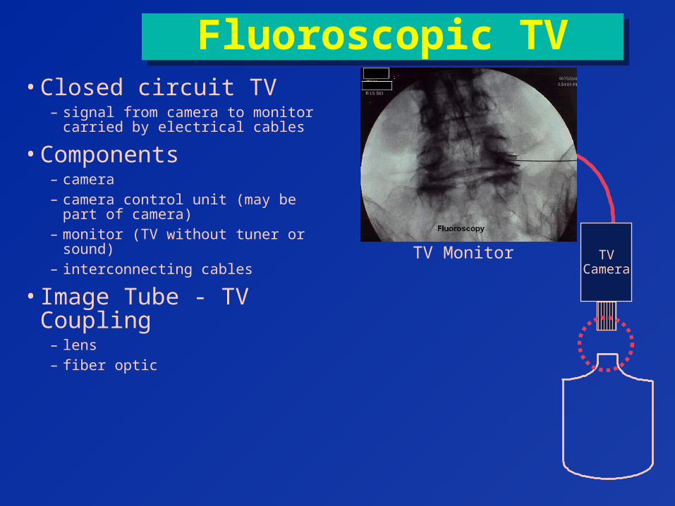
TV Camera
• converts light to coded electrical signal
• Camera Tube– vidicon
» cheapest / compact / laggy
– plumbicon» enhanced vidicon / less lag
– CCD» Semiconductor» not a tube
TVCamera
Light
electricalsignal

Vidicon TV Pick-up Tube

Charge Coupled Device (CCD)• semiconductor device
– not vacuum tube
• stores charge in small discrete wellswells• transfers charge to readout device one line at a
time• no readout beam, focusing or deflection coils• shorter than vidicons• resolution limited by number of scan lines
(element array)

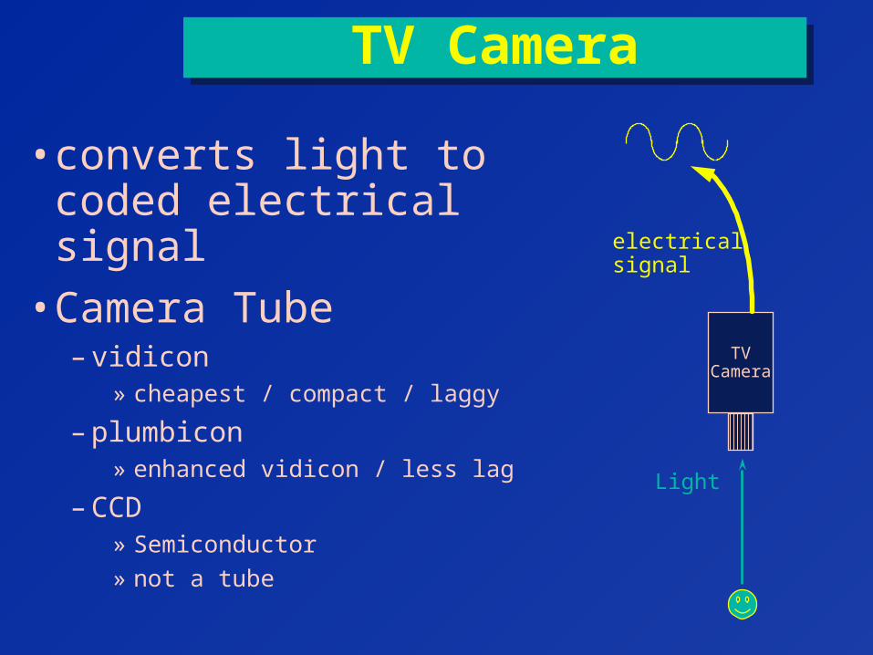
Monochrome Television Monitor
• Another vacuum tube– electron beam scanned along fluorescent screen

Monochrome TV Monitor Elementselectron gunelectron guncontrol gridcontrol grid
controls beam intensity at each location
anodeanodefluorescent screenscreenexternal focusing coilfocusing coilexternal deflection coilsdeflection coils
(steer electron beam)

Television Scanning
• beam scanning for standard TV– 525 lines in total image– 30 images (framesframes) scanned per second
• Oscillators– Vertical– Horizontal Vertical
(Slower)
Horizontal(Faster)

TV Interlacing• frameframe scanned in two passes, first the odd lines then
the even– One frame takes 1/30th second– avoids flicker
• each pass called a fieldfield– takes 1/60th second
1st Field (Odd lines) 2nd Field (Even lines)
+ =
+ = One Frame
1/60th sec. 1/60th sec. 1/30th sec.
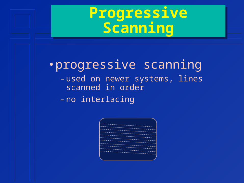
Progressive Scanning
• progressive scanning– used on newer systems, lines scanned in
order– no interlacing

Synchronization• TV Camera & Monitor must be
synchronized– beam at same place on image
• special sync pulses sent at end of each horizontal line & vertical field
• retrace– horizontal retrace
» beam returned to left side of screen– vertical retrace
» beam returned to the top of screen– Turns off video during retrace
Vertical Retrace
Horizontal Retrace
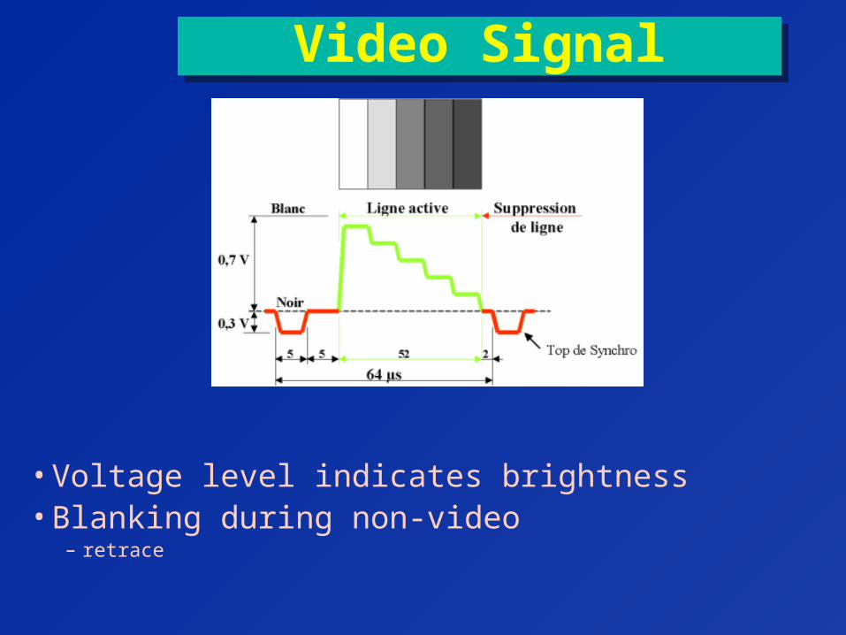
Video Signal
• Voltage level indicates brightness• Blanking during non-video
– retrace
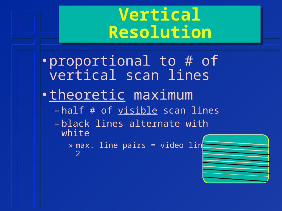
Vertical Resolution
• proportional to # of vertical scan lines
• theoretic maximum– half # of visible scan lines– black lines alternate with white
» max. line pairs = video lines / 2
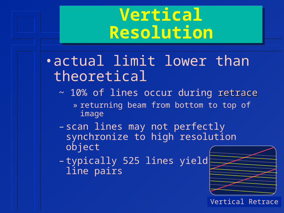
Vertical Resolution
• actual limit lower than theoretical~ 10% of lines occur during retraceretrace
» returning beam from bottom to top of image
– scan lines may not perfectly synchronize to high resolution object
– typically 525 lines yield ~185 line pairs
Vertical Retrace
Bandwidth (Bandpass)
• Highest frequency that video components are designed to transmit or display
• no sharp frequency cutoff – not all frequencies transmitted or displayed
with same quality– Gradual degrading
Bandwidth (Bandpass)
• What it means for video– camera
» how fast camera can turn electrical signal on & off
– monitor» how rapid a change in incoming electrical signal
monitor can display
– determines # of pairs which can be displayed on one horizontal display line
» horizontal resolutionhorizontal resolution

Bandwidth
• cycles per scan line = line pairs per scan line
• higher bandwidth = $$$
Bandwidth = [Horizontal Resolution] X [Video Lines] X [Frame Rate]
cycles------------scan line
lines--------- frame
frames--------- sec
cycles---------- sec
= X X
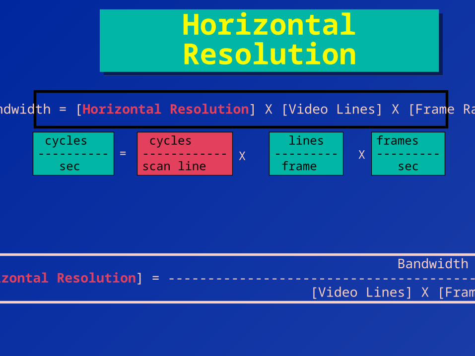
Horizontal Resolution
Bandwidth = [Horizontal Resolution] X [Video Lines] X [Frame Rate]
cycles------------scan line
lines--------- frame
frames--------- sec
cycles---------- sec
Bandwidth[Horizontal Resolution] = ------------------------------------------- [Video Lines] X [Frame Rate]
= X X

Resolution Summary• Vertical resolution depends on
# of scan lines
• Horizontal resolution depends on– bandwidth– # of scan lines– frame rate
• Systems designed to yield approx. equal horizontal & vertical resolution
~ 4.5 MHz typical bandwidth for 525 line system– higher bandwidth required for higher line rates
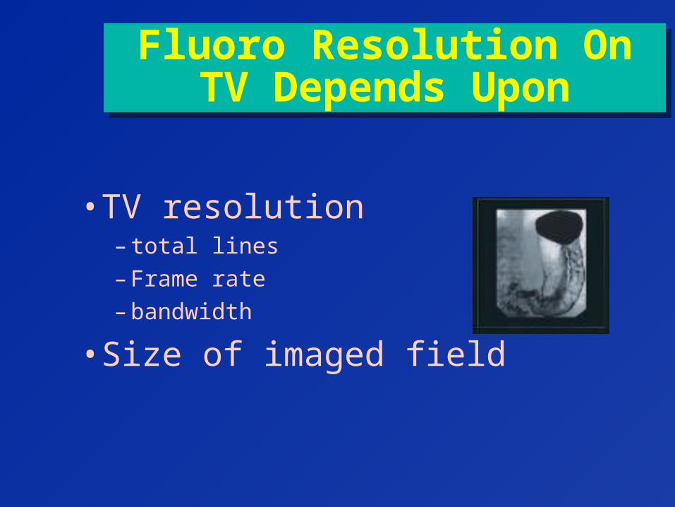
Fluoro Resolution On TV Depends Upon
• TV resolution– total lines– Frame rate– bandwidth
• Size of imaged field
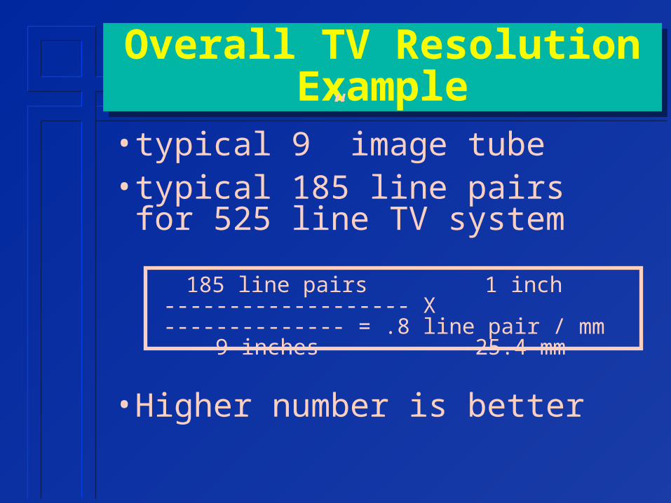
Overall TV Resolution Example
• typical 9” image tube• typical 185 line pairs for 525 line
TV system
185 line pairs 1 inch------------------- X -------------- = .8 line pair / mm 9 inches 25.4 mm
• Higher number is better

Conventional TV Systems
• Fluoro Resolution– 9 inch mode => 0.8 line pairs / mm– 6 inch mode => 1.2 line pairs / mm– 4 inch mode => 1.6 line pairs / mm
• Conventional TV vs. Image tube– TV resolution generally poorer than image tube (3-5
line pairs / mm typical for II)– to view image tube at full resolution requires
photographing output phosphor» photospot camera (100 mm, 105 mm)» cine camera
Overall System Contrast
• vidicon reduces contrast by about 20%
• monitor enhances contrast by up to 2X
– adjustable by operator– brightness & contrast controls

Lag• Description
– stickiness in image » apparent during tower motion in fluoro» not totally undesirable
• smoothes quantum noise
• Cause– time required for image to build up & decay on TV tube
target
• Etc.– vidicons exhibit more lag– plumbicons display more quantum noise
More Lag = Less Quantum Noise

TV Gain
Output electrical signal amplitude--------------------------------------------
light input amplitudeTV
Camera
Light
electricalsignal
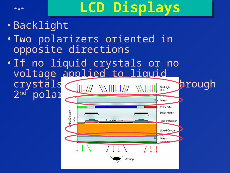
LCD Displays• Backlight• Two polarizers oriented in opposite directions• If no liquid crystals or no voltage applied to
liquid crystals, no light passes through 2nd polarizer
***
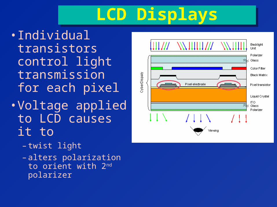
LCD Displays• Individual
transistors control light transmission for each pixel
• Voltage applied to LCD causes it to
– twist light– alters polarization to
orient with 2nd polarizer
Automatic Brightness Control• automatic variation of fluoro technique
based upon image brightness• Technique depends on absorber

Automatic Brightness Control
• brightness sensing– photomultiplier tube sensing light from image tube
output phosphor OR
– intensity of electrical signal from TV camera
• brightness signal sent to generator• Generator adjusts technique to
achieve desired brightness

Automatic Brightness Implementations
• operator sets kVp / generator sets mA
• operator sets mA / generator sets kVp
• system sets both mA & kVp
• system adjusts pulse width– only on some cath lab equipment (expensive)
Fluoro Recording
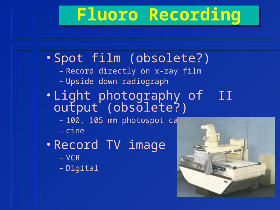
• Spot film (obsolete?)– Record directly on x-ray film – Upside down radiograph
• Light photography of II output (obsolete?)
– 100, 105 mm photospot camera– cine
• Record TV image– VCR– Digital

Spot Film• Upside-down radiograph• phototimed• delay before exposure
– switch from fluoro to radiographicmode
– heat up filament– speed up rotor (sometimes)– move cassette into position

Cine
• Viewed as motion picture• records light image from output
phosphor • selectable frame rate
– 7.5/ 15, 30,60,120 frames/second» requires secondary switching generator
– rates greater than 30 f/sec. only used in pediatrics
• patient exposure proportional to frame rate

Recording TV Signal
• VCR Magnetic Tape• Digital
VCR Magnetic Tape
• VHS or SVHS• limited tape shelf life (2 years)• long access times• limited bandwidth
Related Documents