Chaos Synchronization and Cryptography for Secure Communications: Applications for Encryption Santo Banerjee Politecnico di Torino, Italy Hershey • New York InformatIon scIence reference

Welcome message from author
This document is posted to help you gain knowledge. Please leave a comment to let me know what you think about it! Share it to your friends and learn new things together.
Transcript
Chaos Synchronization and Cryptography for Secure Communications:Applications for Encryption
Santo BanerjeePolitecnico di Torino, Italy
Hershey • New YorkInformatIon scIence reference

Director of Editorial Content: Kristin KlingerDirector of Book Publications: Julia MosemannAcquisitions Editor: Lindsay JohnstonDevelopment Editor: Christine BuftonPublishing Assistant: Casey ConapitskiTypesetter: Deanna Jo ZombroProduction Editor: Jamie SnavelyCover Design: Lisa TosheffPrinted at: Lightning Source
Published in the United States of America by Information Science Reference (an imprint of IGI Global)701 E. Chocolate AvenueHershey PA 17033Tel: 717-533-8845Fax: 717-533-8661E-mail: [email protected] site: http://www.igi-global.com
Copyright © 2011 by IGI Global. All rights reserved. No part of this publication may be reproduced, stored or distributed in any form or by any means, electronic or mechanical, including photocopying, without written permission from the publisher.Product or company names used in this set are for identification purposes only. Inclusion of the names of the products or com-panies does not indicate a claim of ownership by IGI Global of the trademark or registered trademark.
Library of Congress Cataloging-in-Publication Data
Chaos synchronization and cryptography for secure communications : applications for encryption / Santo Banerjee, editor. p. cm. Includes bibliographical references and index. Summary: "This book explores the combination of ordinary and time delayed systems and their applications in cryptographic encoding"--Provided by publisher. ISBN 978-1-61520-737-4 (hardcover) -- ISBN 978-1-61520-738-1 (ebook) 1. Telecommunication--Security measures. 2. Chaotic behavior in systems. 3. Cryptography. 4. Data encryption (Computer science) 5. Synchronization. I. Banerjee, Santo, 1976- TK5102.94.C523 2010 621.382--dc22 2010015993
British Cataloguing in Publication DataA Cataloguing in Publication record for this book is available from the British Library.
All work contributed to this book is new, previously-unpublished material. The views expressed in this book are those of the authors, but not necessarily of the publisher.

386
Copyright © 2011, IGI Global. Copying or distributing in print or electronic forms without written permission of IGI Global is prohibited.
Chapter 17
Unmasking Optical Chaotic Cryptosystems
Based on Delayed Optoelectronic Feedback
Silvia OrtínInstituto de Física de Cantabria (CSIC-Universidad de Cantabria), Spain
Luis PesqueraInstituto de Física de Cantabria (CSIC-Universidad de Cantabria), Spain
INTRODUCTION
Chaotic signals typically have broadband spectrum. This property is desirable for applications that require robustness against interference, jamming and low detection probability. Those issues have been addressed by traditional communication systems by using spread spectrum and frequency hopping modulations. In chaos-based communications the broadband chaotic signal is generated at the physical layer instead of algorithmically. Additionally, chaotic carriers offer a certain degree of intrinsic privacy in the data
ABSTRACT
The authors analyze the security of optical chaotic communication systems. The chaotic carrier is gen-erated by a laser diode subject to delayed optoelectronic feedback. Transmitters with one and two fixed delay times are considered. A new type of neural networks, modular neural networks, is used to recon-struct the nonlinear dynamics of the transmitter from experimental time series in the single-delay case, and from numerical simulations in single and two-delay cases. The authors show that the complexity of the model does not increase when the delay time is increased, in spite of the very high dimension of the chaotic attractor. However, it is found that nonlinear dynamics reconstruction is more difficult when the feedback strength is increased. The extracted model is used as an unauthorized receiver to recover the message. Therefore, the authors conclude that optical chaotic cryptosystems based on optoelectronic feedback systems with several fixed time delays are vulnerable.
DOI: 10.4018/978-1-61520-737-4.ch017

387
Unmasking Optical Chaotic Cryptosystems Based on Delayed Optoelectronic Feedback
transmission. In chaotic communication systems (Cuomo et al., 1993b; Colet & Roy, 1994) the masking of the message is performed at the physical layer by embedding the signal within a chaotic carrier in the emitter. The recovery of the message is based on the synchronization phenomenon (Ashwin, 2003) by which a receiver, quite similar to the transmitter, is able to reproduce the chaotic part of the transmitted signal. After synchronization occurs, the decoding of the message is straightforward by comparing the input and output of the receiver. Privacy in chaotic communication systems results from the fact that the eavesdropper must have the proper hardware and parameter settings in order to recover the message. The suitability of chaos-based optical communication systems for encrypting gigabit signals has been recently demonstrated in an installed optical network infrastructure of approximately 120 km that covers the metropolitan area of Athens (Argyris et al., 2005). However, the security of these systems remains the key issue to be addressed.
In conventional encryption techniques a key is used to alter the information symbols. The transmit-ter and the receiver share the key so that the information can be recovered. In a chaotic communication system the transmitter generates a time-evolving chaotic waveform that is used to mask the message. The cryptographic key relies on structural characteristics of the hardware as well as on the set of operating parameters chosen for the system. The message can be recovered with a receiver such that its configura-tion and parameter settings are matched to those of the transmitter. Encryption is achieved by encoding at the physical layer, providing full compatibility to conventional software encryption techniques. Dy-namical encoding with a chaotic waveform can then be considered as an additional layer of encryption.
Chaos cryptography is a recent encryption technique (the idea was proposed in the early 90s), and it will take some time for its security analysis to mature. Some rules have been suggested to achieve a reasonable degree of security (Alvarez & Li, 2006). Methods to quantify the cryptanalysis of chaotic encryption schemes have been also proposed (Tenny & Tsimring, 2004). However, more research needs to be done to develop a systematic cryptographic approach for the analysis of the security of different chaotic communication systems. Many chaos-based encryption schemes have been proposed, and many of those schemes have been broken later on.
Some chaotic encryption systems were broken even without reconstructing the transmitter’s chaotic dynamics, that is, without searching for the secret key that was used to encrypt the message. This kind of attack is usually applicable if the statistical properties of the ciphertext change as a result of changing the transmitted plaintext. Return maps (Perez & Cerdeira, 1995) and spectral analysis (Yang et al., 1998a) of the transmitted ciphertext have been used to decode the message eliminating the need to reconstruct the secret dynamics.
Another type of attacks relies on partial knowledge of the chaotic dynamics. If the unauthorized re-ceiver knows the type of attractor used for the transmission and reception, but ignores the precise value of the parameters, generalized synchronization (Rulkov et al., 1995) can be used to extract the message (Yang et al., 1998b). In this case a generalized synchronization between transmitter and unauthorized receiver with a different set of parameters occurs, and the message is decoded using variations in the synchronization error. In another case the unauthorized receiver knows that the transmitter is an erbium-doped fiber-ring laser with two delay loops (Geddes et al., 1999). The dynamics of this chaotic transmitter is high dimensional (dimension greater than 10). However, using a simplified lower dimensional model with four parameters, the message can be decoded by estimating the model parameters. In this case the laser dynamics was governed almost entirely by the modulation signal, which echoed in the two loops, and nonlinear effects could be neglected to a good approximation.
388
Unmasking Optical Chaotic Cryptosystems Based on Delayed Optoelectronic Feedback
In another type of attacks the unauthorized receiver attempts to reconstruct the secret chaotic dynam-ics of the transmitter without having any a-priori knowledge about the type of dynamics used. Nonlinear dynamics forecasting techniques have been used to extract the chaotic carrier signal (Short, 1994; 1996; Short & Parker, 1998). The message signal can be obtained by removing the carrier signal from the transmitted ciphertext signal.
Two important factors to privacy considerations in chaotic communication systems are the effort required to obtain the necessary parameters for a matched receiver and the dimensionality of the chaos. Important aspects of receiver design are the number of parameters that have to be matched for informa-tion recovery and the precision required for parameter matching. Higher dimensional signals, especially those involving hyperchaotic dynamics, are likely to provide improved security. Chaotic communication systems were originally implemented with electronic circuits with low dimensional chaos (Kocarev et al., 1992; Cuomo & Oppenheim, 1993a). Unfortunately, messages encoded with low dimensional chaotic carriers can be often extracted using standard nonlinear techniques (Perez & Cerdeira, 1995; Short & Parker, 1998). Nonlinear systems with delayed feedback can have many positive Lyapunov exponents and chaotic attractors whose dimension increases with the delay time, reaching very high values (Farmer, 1982). It is then computationally difficult to reconstruct the nonlinear dynamics of these systems with time-series analysis techniques based on the standard embedding approach. However, it is possible to recover the equation that describes a single-variable time-delay system without using embedding techniques by exploiting the particular structure of these systems. In that approach it is as-sumed that the structure of that equation is known, and only the functions and parameters are unkown. In this way chaotic cryptosystems based on time-delay systems can be unmasked in spite of the very high dimension of the chaotic carrier (Zhou & Lai, 1999; Ponomarenko & Prokhorov, 2002; Udaltsov et al., 2003; Robilliard et al., 2006).
When the structure of the equations that govern a time-delay system is unknown, an embedding-like approach has been used to recover the dynamics with a local linear model (Hegger et al., 1998; Bünner et al., 2000a; 2000b). This method works with a special embedding space that includes both short time and feedback-time delayed values of the system variable. In this way the dynamics is reconstructed in a space with a dimension much smaller than the attractor´s dimension. The dimension of this space is independent of the delay time. In this chapter we use this special embedding space to reconstruct the nonlinear dynamics of semiconductor lasers subject to delayed optoelectronic feedback. A global non-linear model based on neural networks will be used for this reconstruction.
Optical systems provide simple ways of generating very high dimensional chaotic carriers that offer the possibility of high transmission rates (Uchida et al., 2005; Donati & Mirasso, 2002). Generation of chaotic signals with high dimension and high information entropy can be achieved in diode lasers by means of delayed feedback. Two schemes based on all-optical and electro-optical feedback have been considered (Argyris et al., 2005). In both systems the dimension of the chaotic attractor increases linearly with the delay time, reach-ing very high values (Vicente et al., 2005). However, the entropy of systems with optoelectronic feedback increases with the feedback strength, whereas it saturates for all-optical feedback systems (Vicente et al., 2005). Therefore the behaviour can be more unpredictable for chaotic carriers based on optoelectronic feed-back. In this work we consider optoelectronic chaos generators with fixed values of the feedback delay time (Goedgebuer et al., 1998a; Larger et al., 1998a). We have recently shown that the nonlinear dynamics of those optical chaotic carriers can be reconstructed by using time series obtained from numerical simulations (Ortín & Pesquera, 2006; Ortín et al., 2007c) and from experimental data (Ortín et al., 2007a; 2007b). The security of chaotic cryptosystems based on optoelectronic feedback with fixed delay time is then compromised.
389
Unmasking Optical Chaotic Cryptosystems Based on Delayed Optoelectronic Feedback
We study in this chapter the security of optical chaotic communication systems based on a chaotic carrier generated by a laser diode subject to delayed optoelectronic feedback. Two different cases with one and two fixed delay times are considered. The chapter is structured as follows. The first Section is devoted to the study of the one fixed delay time case through numerical simulations. We introduce the model for a chaotic generator based on a semiconductor laser with delayed electro-optical feedback (Larger et al., 1998a; Goedgebuer et al., 1998a). The value of the delay time is extracted from the nu-merical time series. This step is crucial to work in the special embedding space that includes both short time and feedback-time delayed values of the system variable. The nonlinear dynamics of the chaotic carrier is reconstructed from numerical simulations by using a new type of modular neural networks. Using this model as an unauthorized receiver, it is shown that the message can be extracted. In the sec-ond Section we apply the previous techniques to recover the message from experimental time series. The experiments were performed in the group of Prof. Laurent Larger (Université de Franche-Comté, Besançon, France). The third Section is devoted to the study of the two fixed delay times case by using numerical simulations. Two different configurations, serial and parallel, are considered. It is shown that in all the cases this cryptosystem can be broken. Finally, we present the conclusions.
ONE-DElAy ChAOTIC SIgNAl gENERATOR: NUMERICAl SIMUlATIONS
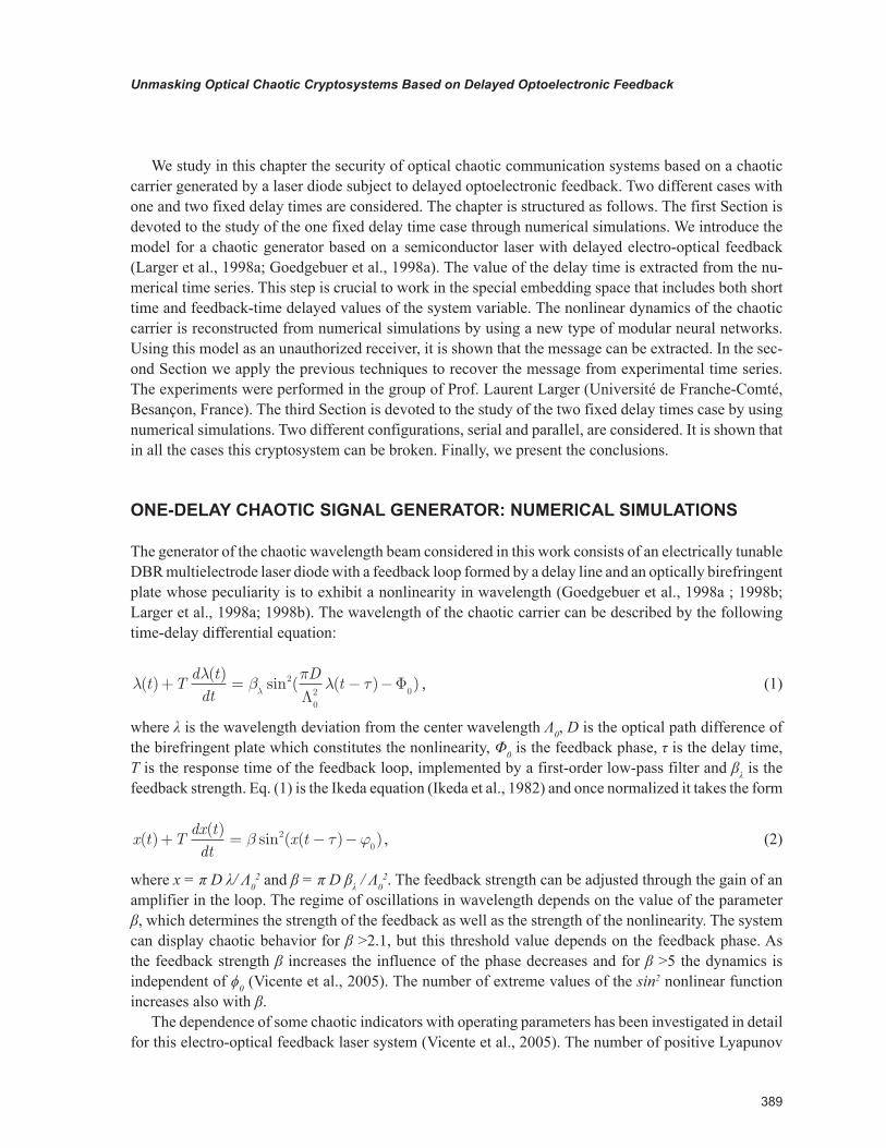
The generator of the chaotic wavelength beam considered in this work consists of an electrically tunable DBR multielectrode laser diode with a feedback loop formed by a delay line and an optically birefringent plate whose peculiarity is to exhibit a nonlinearity in wavelength (Goedgebuer et al., 1998a ; 1998b; Larger et al., 1998a; 1998b). The wavelength of the chaotic carrier can be described by the following time-delay differential equation:
λλ
βπλ τλ( )
( )sin ( ( ) )t T
d tdt
Dt+ = − −2
02 0Λ
Φ , (1)
where λ is the wavelength deviation from the center wavelength Λ0, D is the optical path difference of the birefringent plate which constitutes the nonlinearity, Φ0 is the feedback phase, τ is the delay time, T is the response time of the feedback loop, implemented by a first-order low-pass filter and βλ is the feedback strength. Eq. (1) is the Ikeda equation (Ikeda et al., 1982) and once normalized it takes the form
x t Tdx tdt
x t( )( )
sin ( ( ) )+ = − −β τ ϕ20
, (2)
where x = π D λ/ Λ02 and β = π D βλ / Λ0
2. The feedback strength can be adjusted through the gain of an amplifier in the loop. The regime of oscillations in wavelength depends on the value of the parameter β, which determines the strength of the feedback as well as the strength of the nonlinearity. The system can display chaotic behavior for β >2.1, but this threshold value depends on the feedback phase. As the feedback strength β increases the influence of the phase decreases and for β >5 the dynamics is independent of ϕ0 (Vicente et al., 2005). The number of extreme values of the sin2 nonlinear function increases also with β.
The dependence of some chaotic indicators with operating parameters has been investigated in detail for this electro-optical feedback laser system (Vicente et al., 2005). The number of positive Lyapunov
390
Unmasking Optical Chaotic Cryptosystems Based on Delayed Optoelectronic Feedback
exponents grows linearly with the delay time. The Kaplan-Yorke dimension also increases linearly with the delay time. Therefore, chaotic attractors with very large dimensions can be achieved. However, the Lyapunov exponents that become positive as the delay time is increased have a very small magnitude. This, together with the fact that the largest positive Lyapunov exponent decreases as the delay time in-creases, yields saturation in the Kolmogorov-Sinai entropy. Therefore, although the system has a larger dimensionality when increasing the delay, its behavior does not become more unpredictable. These re-sults suggest that increasing the delay time beyond the value at which the entropy saturates will neither yield a better masking nor improve the security. Unlike all-optical feedback systems, in these electro-optical systems the feedback is nonlinear while the laser operates in the linear regime. The number of positive Lyapunov exponents as well as their value increases with the feedback strength in a linear way. Therefore, the Kaplan-Yorke dimension and the Kolmogorov-Sinai entropy grow also linearly with the feedback strength. Then a way to achieve a better masking and more secure encoding is to increase the nonlinear feedback strength.
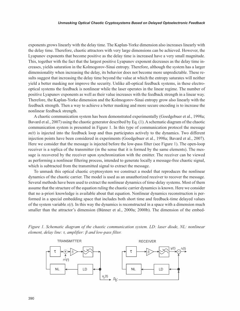
A chaotic communication system has been demonstrated experimentally (Goedgebuer et al., 1998a; Bavard et al., 2007) using the chaotic generator described by Eq. (1). A schematic diagram of the chaotic communication system is presented in Figure 1. In this type of communication protocol the message m(t) is injected into the feedback loop and thus participates actively to the dynamics. Two different injection points have been considered in experiments (Goedgebuer et al., 1998a; Bavard et al., 2007). Here we consider that the message is injected before the low-pass filter (see Figure 1). The open-loop receiver is a replica of the transmitter (in the sense that it is formed by the same elements). The mes-sage is recovered by the receiver upon synchronization with the emitter. The receiver can be viewed as performing a nonlinear filtering process, intended to generate locally a message-free chaotic signal, which is subtracted from the transmitted signal to extract the message.
To unmask this optical chaotic cryptosystem we construct a model that reproduces the nonlinear dynamics of the chaotic carrier. The model is used as an unauthorized receiver to recover the message. Several methods have been used to extract the nonlinear dynamics of time-delay systems. Most of them assume that the structure of the equation ruling the chaotic carrier dynamics is known. Here we consider that no a-priori knowledge is available about that equation. Nonlinear dynamics reconstruction is per-formed in a special embedding space that includes both short time and feedback-time delayed values of the system variable x(t). In this way the dynamics is reconstructed in a space with a dimension much smaller than the attractor’s dimension (Bünner et al., 2000a; 2000b). The dimension of the embed-
Figure 1. Schematic diagram of the chaotic communication system. LD: laser diode, NL: nonlinear element, delay line: τ, amplifier: β and low-pass filter.
391
Unmasking Optical Chaotic Cryptosystems Based on Delayed Optoelectronic Feedback
ding space turns out to be independent of the delay time and thus of the dimensionality of the attractor dynamics. In this Section we use time series of x(t) obtained from numerical simulations of Eq. (2) to reconstruct the nonlinear dynamics of one-delay chaotic carriers.
We have carried out numerical simulations of Eq. (2) using the Adams-Bashforth-Moulton predictor-corrector scheme (Press et al., 1992) with an integration step of 0.01. To study the effect of the nonlinearity strength we have considered several values of β in the range from β = 5 (low nonlinearity strength) to β = 50 (high nonlinearity strength). The maximum value of β that has been achieved in experiments is around 22 (Goedgebuer et al., 1998a). Several values of T and τ have been also considered. The feedback phase is ϕ0 = 0.26 π.
Time-Delay Extraction
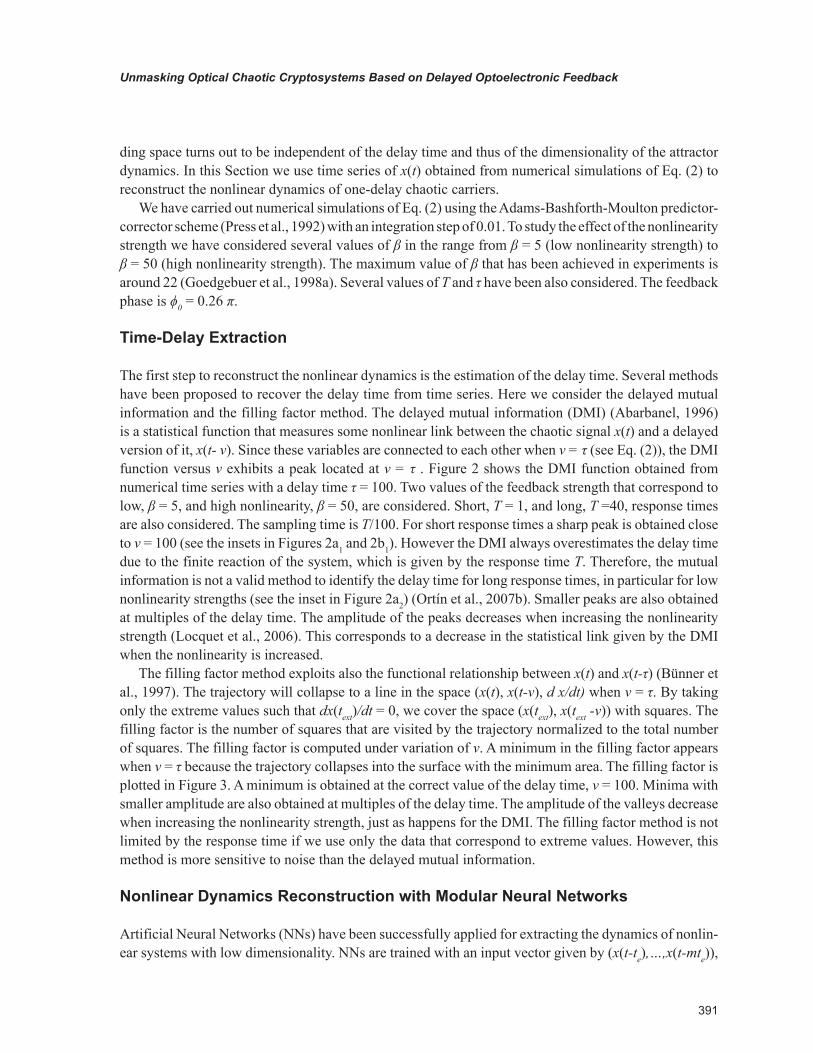
The first step to reconstruct the nonlinear dynamics is the estimation of the delay time. Several methods have been proposed to recover the delay time from time series. Here we consider the delayed mutual information and the filling factor method. The delayed mutual information (DMI) (Abarbanel, 1996) is a statistical function that measures some nonlinear link between the chaotic signal x(t) and a delayed version of it, x(t- ν). Since these variables are connected to each other when ν = τ (see Eq. (2)), the DMI function versus ν exhibits a peak located at ν = τ . Figure 2 shows the DMI function obtained from numerical time series with a delay time τ = 100. Two values of the feedback strength that correspond to low, β = 5, and high nonlinearity, β = 50, are considered. Short, T = 1, and long, T =40, response times are also considered. The sampling time is T/100. For short response times a sharp peak is obtained close to ν = 100 (see the insets in Figures 2a1 and 2b1). However the DMI always overestimates the delay time due to the finite reaction of the system, which is given by the response time Τ. Therefore, the mutual information is not a valid method to identify the delay time for long response times, in particular for low nonlinearity strengths (see the inset in Figure 2a2) (Ortín et al., 2007b). Smaller peaks are also obtained at multiples of the delay time. The amplitude of the peaks decreases when increasing the nonlinearity strength (Locquet et al., 2006). This corresponds to a decrease in the statistical link given by the DMI when the nonlinearity is increased.
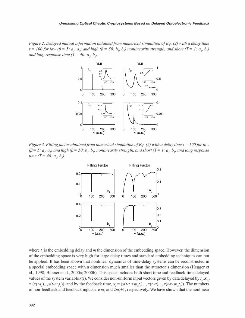
The filling factor method exploits also the functional relationship between x(t) and x(t-τ) (Bünner et al., 1997). The trajectory will collapse to a line in the space (x(t), x(t-ν), d x/dt) when ν = τ. By taking only the extreme values such that dx(text)/dt = 0, we cover the space (x(text), x(text -ν)) with squares. The filling factor is the number of squares that are visited by the trajectory normalized to the total number of squares. The filling factor is computed under variation of ν. A minimum in the filling factor appears when ν = τ because the trajectory collapses into the surface with the minimum area. The filling factor is plotted in Figure 3. A minimum is obtained at the correct value of the delay time, ν = 100. Minima with smaller amplitude are also obtained at multiples of the delay time. The amplitude of the valleys decrease when increasing the nonlinearity strength, just as happens for the DMI. The filling factor method is not limited by the response time if we use only the data that correspond to extreme values. However, this method is more sensitive to noise than the delayed mutual information.
Nonlinear Dynamics Reconstruction with Modular Neural Networks
Artificial Neural Networks (NNs) have been successfully applied for extracting the dynamics of nonlin-ear systems with low dimensionality. NNs are trained with an input vector given by (x(t-te),…,x(t-mte)),
392
Unmasking Optical Chaotic Cryptosystems Based on Delayed Optoelectronic Feedback
where te is the embedding delay and m the dimension of the embedding space. However, the dimension of the embedding space is very high for large delay times and standard embedding techniques can not be applied. It has been shown that nonlinear dynamics of time-delay systems can be reconstructed in a special embedding space with a dimension much smaller than the attractor´s dimension (Hegger et al., 1998; Bünner et al., 2000a; 2000b). This space includes both short time and feedback-time delayed values of the system variable x(t). We consider non-uniform input vectors given by data delayed by te, xn f = (x(t-te),..,x(t-m1te)), and by the feedback time, xf = (x(t-τ +m2te),.., x(t -τ),.., x(t-τ- m2te)). The numbers of non-feedback and feedback inputs are m1 and 2m2+1, respectively. We have shown that the nonlinear
Figure 2. Delayed mutual information obtained from numerical simulation of Eq. (2) with a delay time τ = 100 for low (β = 5: a1, a2) and high (β = 50: b1, b2) nonlinearity strength, and short (T = 1: a1, b1) and long response time (T = 40: a2, b2).
Figure 3. Filling factor obtained from numerical simulation of Eq. (2) with a delay time τ = 100 for low (β = 5: a1, a2) and high (β = 50: b1, b2) nonlinearity strength, and short (T = 1: a1, b1) and long response time (T = 40: a2, b2).
393
Unmasking Optical Chaotic Cryptosystems Based on Delayed Optoelectronic Feedback
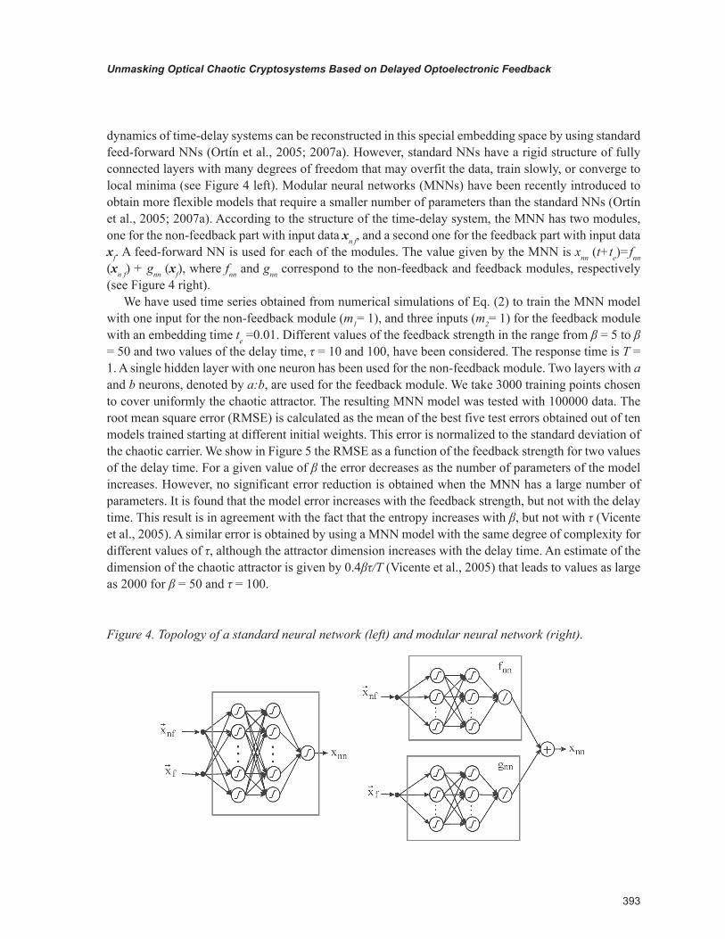
dynamics of time-delay systems can be reconstructed in this special embedding space by using standard feed-forward NNs (Ortín et al., 2005; 2007a). However, standard NNs have a rigid structure of fully connected layers with many degrees of freedom that may overfit the data, train slowly, or converge to local minima (see Figure 4 left). Modular neural networks (MNNs) have been recently introduced to obtain more flexible models that require a smaller number of parameters than the standard NNs (Ortín et al., 2005; 2007a). According to the structure of the time-delay system, the MNN has two modules, one for the non-feedback part with input data xn f, and a second one for the feedback part with input data xf. A feed-forward NN is used for each of the modules. The value given by the MNN is xnn (t+te)=fnn (xn f) + gnn (xf), where fnn and gnn correspond to the non-feedback and feedback modules, respectively (see Figure 4 right).
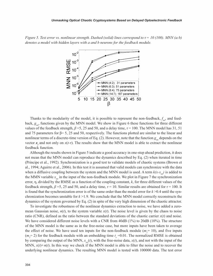
We have used time series obtained from numerical simulations of Eq. (2) to train the MNN model with one input for the non-feedback module (m1= 1), and three inputs (m2= 1) for the feedback module with an embedding time te =0.01. Different values of the feedback strength in the range from β = 5 to β = 50 and two values of the delay time, τ = 10 and 100, have been considered. The response time is T = 1. A single hidden layer with one neuron has been used for the non-feedback module. Two layers with a and b neurons, denoted by a:b, are used for the feedback module. We take 3000 training points chosen to cover uniformly the chaotic attractor. The resulting MNN model was tested with 100000 data. The root mean square error (RMSE) is calculated as the mean of the best five test errors obtained out of ten models trained starting at different initial weights. This error is normalized to the standard deviation of the chaotic carrier. We show in Figure 5 the RMSE as a function of the feedback strength for two values of the delay time. For a given value of β the error decreases as the number of parameters of the model increases. However, no significant error reduction is obtained when the MNN has a large number of parameters. It is found that the model error increases with the feedback strength, but not with the delay time. This result is in agreement with the fact that the entropy increases with β, but not with τ (Vicente et al., 2005). A similar error is obtained by using a MNN model with the same degree of complexity for different values of τ, although the attractor dimension increases with the delay time. An estimate of the dimension of the chaotic attractor is given by 0.4βτ/Τ (Vicente et al., 2005) that leads to values as large as 2000 for β = 50 and τ = 100.
Figure 4. Topology of a standard neural network (left) and modular neural network (right).
394
Unmasking Optical Chaotic Cryptosystems Based on Delayed Optoelectronic Feedback
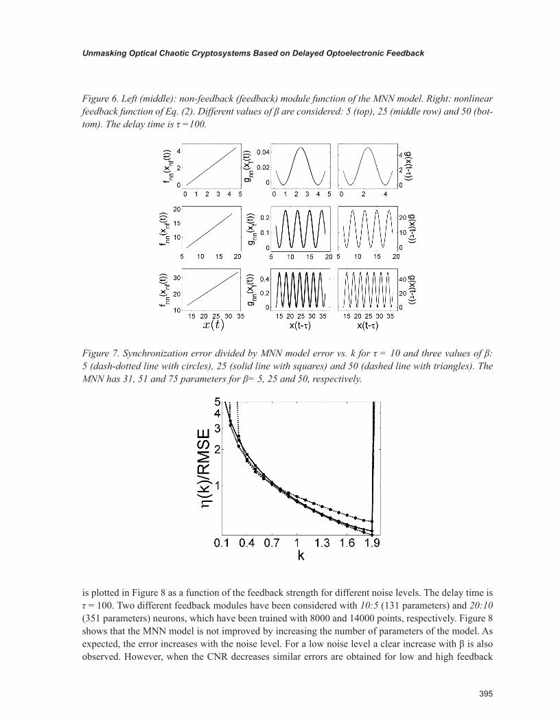
Thanks to the modularity of the model, it is possible to represent the non-feedback, fnn, and feed-back, gnn, functions given by the MNN model. We show in Figure 6 these functions for three different values of the feedback strength, β =5, 25 and 50, and a delay time, τ = 100. The MNN model has 31, 51 and 75 parameters for β= 5, 25 and 50, respectively. The functions plotted are similar to the linear and nonlinear terms of a discrete-time version of Eq. (2). However, note that the function gnn depends on the vector xf and not only on x(t-τ). The results show that the MNN model is able to extract the nonlinear feedback function.
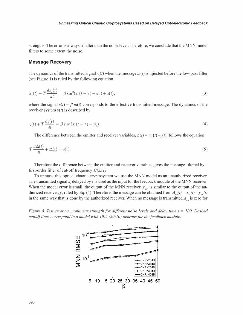
Although the results shown in Figure 5 indicate a good accuracy in one-step ahead prediction, it does not mean that the MNN model can reproduce the dynamics described by Eq. (2) when iterated in time (Principe et al., 1992). Synchronization is a good test to validate models of chaotic systems (Brown et al., 1994; Aguirre et al., 2006). In this test it is assumed that valid models can synchronize with the data when a diffusive coupling between the system and the MNN model is used. A term k(x-xnn) is added to the MMN variable xnn in the input of the non-feedback module. We plot in Figure 7 the synchronization error, η, divided by the RMSE as a function of the coupling constant, k, for three different values of the feedback strength, β =5, 25 and 50, and a delay time, τ = 10. Similar results are obtained for τ = 100. It is found that the synchronization error is of the same order than the model error for k >0.4 until the syn-chronization becomes unstable for k >1.9. We conclude that the MNN model correctly reconstructs the dynamics of the system governed by Eq. (2) in spite of the very high dimension of the chaotic attractor.
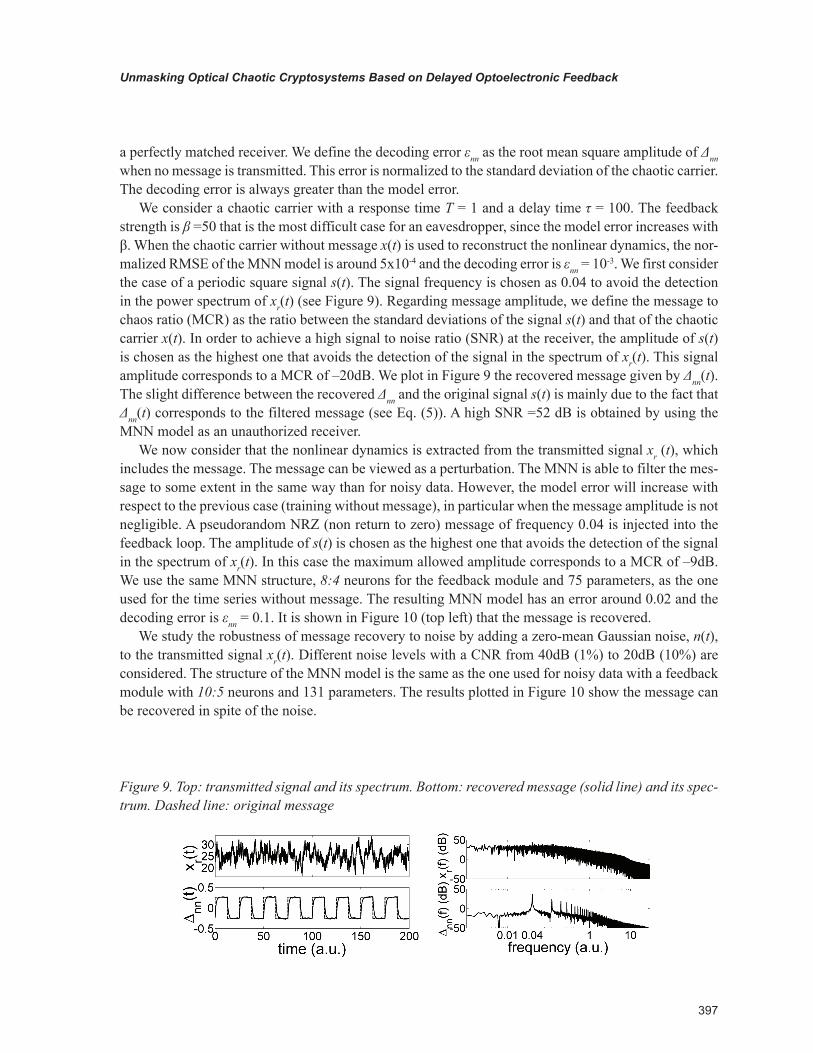
To investigate the robustness of the nonlinear dynamics extraction to noise, we have added a zero-mean Gaussian noise, n(t), to the system variable x(t). The noise level is given by the chaos to noise ratio (CNR), defined as the ratio between the standard deviations of the chaotic carrier x(t) and noise. We have considered different noise levels with a CNR from 40dB (1%) to 20dB (10%). The structure of the MNN model is the same as in the free-noise case, but more inputs have been taken to average the effect of noise. We have used ten inputs for the non-feedback module (m1= 10), and five inputs (m2= 2) for the feedback module with an embedding time te =0.01. The normalized RMSE is obtained by comparing the output of the MNN, xnn(t), with the free-noise data, x(t), and not with the input of the MNN, x(t)+n(t). In this way we check if the MNN model is able to filter the noise and to recover the underlying nonlinear dynamics. The resulting MNN model is tested with 100000 data. The test error
Figure 5. Test error vs. nonlinear strength. Dashed (solid) lines correspond to τ = 10 (100). MNN (a:b) denotes a model with hidden layers with a and b neurons for the feedback module.
395
Unmasking Optical Chaotic Cryptosystems Based on Delayed Optoelectronic Feedback
is plotted in Figure 8 as a function of the feedback strength for different noise levels. The delay time is τ = 100. Two different feedback modules have been considered with 10:5 (131 parameters) and 20:10 (351 parameters) neurons, which have been trained with 8000 and 14000 points, respectively. Figure 8 shows that the MNN model is not improved by increasing the number of parameters of the model. As expected, the error increases with the noise level. For a low noise level a clear increase with β is also observed. However, when the CNR decreases similar errors are obtained for low and high feedback
Figure 6. Left (middle): non-feedback (feedback) module function of the MNN model. Right: nonlinear feedback function of Eq. (2). Different values of β are considered: 5 (top), 25 (middle row) and 50 (bot-tom). The delay time is τ =100.
Figure 7. Synchronization error divided by MNN model error vs. k for τ = 10 and three values of β: 5 (dash-dotted line with circles), 25 (solid line with squares) and 50 (dashed line with triangles). The MNN has 31, 51 and 75 parameters for β= 5, 25 and 50, respectively.
396
Unmasking Optical Chaotic Cryptosystems Based on Delayed Optoelectronic Feedback
strengths. The error is always smaller than the noise level. Therefore, we conclude that the MNN model filters to some extent the noise.
Message Recovery
The dynamics of the transmitted signal xr(t) when the message m(t) is injected before the low-pass filter (see Figure 1) is ruled by the following equation
x t Tdx t
dtx t s t
rr
r( )
( )sin ( ( ) ) ( ),+ = − − +β τ ϕ2
0 (3)
where the signal s(t) = β m(t) corresponds to the effective transmitted message. The dynamics of the receiver system y(t) is described by
y t Tdy tdt
x tr
( )( )
sin ( ( ) ).+ = − −β τ ϕ20
(4)
The difference between the emitter and receiver variables, Δ(t) = xr (t) –y(t), follows the equation
Td tdt
t s t∆
∆( )
( ) ( ).+ = (5)
Therefore the difference between the emitter and receiver variables gives the message filtered by a first-order filter of cut-off frequency 1/(2πT).
To unmask this optical chaotic cryptosystem we use the MNN model as an unauthorized receiver. The transmitted signal xr delayed by τ is used as the input for the feedback module of the MNN receiver. When the model error is small, the output of the MNN receiver, ynn, is similar to the output of the au-thorized receiver, y, ruled by Eq. (4). Therefore, the message can be obtained from Δnn(t) = xr (t) – ynn(t) in the same way that is done by the authorized receiver. When no message is transmitted Δnn is zero for
Figure 8. Test error vs. nonlinear strength for different noise levels and delay time τ = 100. Dashed (solid) lines correspond to a model with 10:5 (20:10) neurons for the feedback module.
397
Unmasking Optical Chaotic Cryptosystems Based on Delayed Optoelectronic Feedback
a perfectly matched receiver. We define the decoding error εnn as the root mean square amplitude of Δnn when no message is transmitted. This error is normalized to the standard deviation of the chaotic carrier. The decoding error is always greater than the model error.
We consider a chaotic carrier with a response time T = 1 and a delay time τ = 100. The feedback strength is β =50 that is the most difficult case for an eavesdropper, since the model error increases with β. When the chaotic carrier without message x(t) is used to reconstruct the nonlinear dynamics, the nor-malized RMSE of the MNN model is around 5x10⁻⁴ and the decoding error is εnn = 10-3. We first consider the case of a periodic square signal s(t). The signal frequency is chosen as 0.04 to avoid the detection in the power spectrum of xr(t) (see Figure 9). Regarding message amplitude, we define the message to chaos ratio (MCR) as the ratio between the standard deviations of the signal s(t) and that of the chaotic carrier x(t). In order to achieve a high signal to noise ratio (SNR) at the receiver, the amplitude of s(t) is chosen as the highest one that avoids the detection of the signal in the spectrum of xr(t). This signal amplitude corresponds to a MCR of –20dB. We plot in Figure 9 the recovered message given by Δnn(t). The slight difference between the recovered Δnn and the original signal s(t) is mainly due to the fact that Δnn(t) corresponds to the filtered message (see Eq. (5)). A high SNR =52 dB is obtained by using the MNN model as an unauthorized receiver.
We now consider that the nonlinear dynamics is extracted from the transmitted signal xr (t), which includes the message. The message can be viewed as a perturbation. The MNN is able to filter the mes-sage to some extent in the same way than for noisy data. However, the model error will increase with respect to the previous case (training without message), in particular when the message amplitude is not negligible. A pseudorandom NRZ (non return to zero) message of frequency 0.04 is injected into the feedback loop. The amplitude of s(t) is chosen as the highest one that avoids the detection of the signal in the spectrum of xr(t). In this case the maximum allowed amplitude corresponds to a MCR of –9dB. We use the same MNN structure, 8:4 neurons for the feedback module and 75 parameters, as the one used for the time series without message. The resulting MNN model has an error around 0.02 and the decoding error is εnn = 0.1. It is shown in Figure 10 (top left) that the message is recovered.
We study the robustness of message recovery to noise by adding a zero-mean Gaussian noise, n(t), to the transmitted signal xr(t). Different noise levels with a CNR from 40dB (1%) to 20dB (10%) are considered. The structure of the MNN model is the same as the one used for noisy data with a feedback module with 10:5 neurons and 131 parameters. The results plotted in Figure 10 show the message can be recovered in spite of the noise.
Figure 9. Top: transmitted signal and its spectrum. Bottom: recovered message (solid line) and its spec-trum. Dashed line: original message
398
Unmasking Optical Chaotic Cryptosystems Based on Delayed Optoelectronic Feedback
ONE-DElAy ChAOTIC SIgNAl gENERATOR: ExpERIMENTS
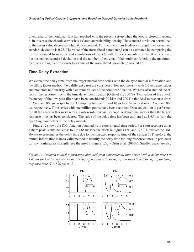
In this Section we apply the same methods used with numerical simulations to recover the message from experimental time series. The generator of the chaotic wavelength beam that is used to encrypt the information is depicted in Figure 11 (Goedgebuer et al., 1998a ; 1998b; Larger et al., 1998a; 1998b). It is formed by a Distributed Bragg Reflector (DBR) two-section tunable laser diode at 1.55 μm with a nonlinear feedback loop containing a birefringent plate, a photodetector, a delay line, an amplifier and a first-order low-pass filter. An electronic corrector is also included in the loop to achieve constant wavelength-independent optical power at the laser output. The nonlinearity in wavelength is induced by the birefringent plate whose fast and slow axes are oriented at 45° to two crossed polarizers. The intensity detected by the photodetector is a sin2 nonlinear function of the wavelength emitted by the laser diode. The cut-off frequency of the low-pass filter determines the response time of the feedback loop.
The delay module consists of a First-In First-Out (FIFO) memory that stores 2048 data in queue order so the first input element goes out the first. A sampling clock fixes the delay value. The clock frequency is limited to a maximum value of 5 MHz by the analog-to-digital and digital-to-analog converters. A minimum clock frequency of 1 MHz is considered to avoid aliasing (Bavard et al., 2007). Therefore the delay time can take values between 0.4 and 2 ms.
The working regime of the device is set by the value of the feedback strength βλ, which can be ad-justed through the gain of the amplifier. The number of extreme values of the sin2 nonlinear function increases with βλ. The system parameters are set to operate in the chaotic regime. The maximum number
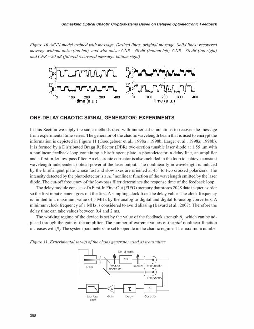
Figure 10. MNN model trained with message. Dashed lines: original message. Solid lines: recovered message without noise (top left), and with noise: CNR =40 dB (bottom left), CNR =30 dB (top right) and CNR =20 dB (filtered recovered message: bottom right)
Figure 11. Experimental set-up of the chaos generator used as transmitter
399
Unmasking Optical Chaotic Cryptosystems Based on Delayed Optoelectronic Feedback
of extrema of the nonlinear function reached with the present set-up when the loop is closed is around 6. In this case the chaotic carrier has a Gaussian probability density. The standard deviation normalized to the mean value decreases when βλ is increased. For the maximum feedback strength the normalized standard deviation is 0.23. The value of the normalized parameter β can be estimated by comparing the results obtained from numerical simulations of Eq. (2) with the experimental results. If we compare the normalized standard deviation and the number of extrema of the nonlinear function, the maximum feedback strength corresponds to a value of the normalized parameter β around 15.
Time-Delay Extraction
We extract the delay time from the experimental time series with the delayed mutual information and the filling factor method. Two different cases are considered: low nonlinearity with 2-3 extreme values and moderate nonlinearity with 6 extreme values of the nonlinear function. We have also studied the ef-fect of the response time in the time delay identification (Ortín et al., 2007b). Two values of the cut-off frequency of the low-pass filter have been considered: 20 kHz and 200 Hz that lead to response times of T = 8 and 800 μs, respectively. A sampling time of 0.1 and 10 μs have been used when T = 8 and 800 μs, respectively. Time series with one million points have been recorded. Data acquisition is performed for all the cases in this work with a 8 bits resolution oscilloscope. A delay time greater than the largest response time has been considered. The value of the delay time has been estimated as 1.65 ms from the operating parameters of the delay module.
Figure 12 shows the DMI function obtained from experimental time series. For short response times a sharp peak is obtained close to ν = 1.65 ms (see the insets in Figures 12a1 and 12b1). However the DMI always overestimates the delay time due to the non-zero response time of the system Τ. Therefore, the mutual information is not a valid method to identify the delay time for long response times, in particular for low nonlinearity strength (see the inset in Figure 12a2) (Ortín et al., 2007b). Smaller peaks are also
Figure 12. Delayed mutual information obtained from experimental time series with a delay time τ = 1.65 ms for low (a1, a2) and moderate (b1, b2) nonlinearity strength, and short (T = 8 μs: a1, b1) and long response time (T = 800 μs: a2, b2).

400
Unmasking Optical Chaotic Cryptosystems Based on Delayed Optoelectronic Feedback
obtained at multiples of the delay time for low nonlinearity strength. These results are similar to those obtained by using numerical simulations.
For noise-free data the filling factor method is not affected by the response time if we use only the data that correspond to extreme values. However, in the presence of noise spurious extrema appear that leads to an overestimation of the delay time for long response times. A rough estimation of the noise is obtained by comparing the recorded time series with a smoothed version of that series. A moving aver-age over 30 μs (3 μs) in the long (short) response time case leads to a 0.028 (0.024) noise level. The noise level is normalized to the standard deviation of the chaotic carrier. In the smoothed time series the number of spurious extrema is reduced. Therefore, the filling factor obtained by using the smoothed time series leads to the correct delay time for both, short and long response times. The resulting filling factor is plotted in Figure 13. A minimum is obtained at the correct value of the delay time. The amplitude of the valleys decreases when increasing the nonlinearity strength, just as happens for the DMI. These results are again similar to those obtained by using numerical simulations.
We have shown (Ortín et al., 2007b) that the correct value of delay time can be also extracted from the recorded experimental time series by using a method based on the forecasting error. In this method a neural network model is trained from the experimental time series by using a non-uniform input vector given by (x(t-te), x(t -ν), x(t-ν- te), x(t-ν-2 te)), where te is the sampling time. The forecasting error of the NN is calculated under variation of ν. A minimum in the error appears at the correct value of the delay time for both, short and long response times. The main drawback of this method is its high computational cost. However, this method seems to be the most appropriate when the noise level is not small.
Nonlinear Dynamics Reconstruction with Modular Neural Networks
We have shown with numerical simulations that the most difficult case for an eavesdropper corresponds to the maximum nonlinear strength. Here we consider the case of a nonlinear function with 5 extrema that
Figure 13. Filling factor obtained from the smoothed experimental time series with a delay time τ = 1.65 ms for low (a1, a2) and moderate (b1, b2) nonlinearity strength, and short (T = 8 μs: a1, b1) and long response time (T = 800 μs: a2, b2).
401
Unmasking Optical Chaotic Cryptosystems Based on Delayed Optoelectronic Feedback
is close to the maximum nonlinear strength reached with the present experimental set-up. The estimated feedback strength β is greater than 12. The cut-off frequency of the low-pass filter is 20 kHz that leads to a response time of 8 μs. The value of the delay time, 0.476 ms, is extracted from the experimental time series.
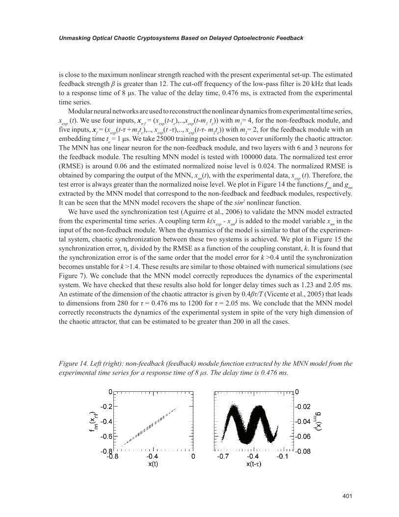
Modular neural networks are used to reconstruct the nonlinear dynamics from experimental time series, xexp (t). We use four inputs, xn f = (xexp(t-te),..,xexp(t-m1 te)) with m1= 4, for the non-feedback module, and five inputs, xf = (xexp(t-τ +m2te),.., xexp(t -τ),.., xexp(t-τ- m2te)) with m2= 2, for the feedback module with an embedding time te = 1 μs. We take 25000 training points chosen to cover uniformly the chaotic attractor. The MNN has one linear neuron for the non-feedback module, and two layers with 6 and 3 neurons for the feedback module. The resulting MNN model is tested with 100000 data. The normalized test error (RMSE) is around 0.06 and the estimated normalized noise level is 0.024. The normalized RMSE is obtained by comparing the output of the MNN, xnn(t), with the experimental data, xexp (t). Therefore, the test error is always greater than the normalized noise level. We plot in Figure 14 the functions fnn and gnn extracted by the MNN model that correspond to the non-feedback and feedback modules, respectively. It can be seen that the MNN model recovers the shape of the sin2 nonlinear function.
We have used the synchronization test (Aguirre et al., 2006) to validate the MNN model extracted from the experimental time series. A coupling term k(xexp - xnn) is added to the model variable xnn in the input of the non-feedback module. When the dynamics of the model is similar to that of the experimen-tal system, chaotic synchronization between these two systems is achieved. We plot in Figure 15 the synchronization error, η, divided by the RMSE as a function of the coupling constant, k. It is found that the synchronization error is of the same order that the model error for k >0.4 until the synchronization becomes unstable for k >1.4. These results are similar to those obtained with numerical simulations (see Figure 7). We conclude that the MNN model correctly reproduces the dynamics of the experimental system. We have checked that these results also hold for longer delay times such as 1.23 and 2.05 ms. An estimate of the dimension of the chaotic attractor is given by 0.4βτ/Τ (Vicente et al., 2005) that leads to dimensions from 280 for τ = 0.476 ms to 1200 for τ = 2.05 ms. We conclude that the MNN model correctly reconstructs the dynamics of the experimental system in spite of the very high dimension of the chaotic attractor, that can be estimated to be greater than 200 in all the cases.
Figure 14. Left (right): non-feedback (feedback) module function extracted by the MNN model from the experimental time series for a response time of 8 μs. The delay time is 0.476 ms.

402
Unmasking Optical Chaotic Cryptosystems Based on Delayed Optoelectronic Feedback
Message Recovery
An optical chaotic cryptosystem has been demonstrated experimentally (Goedgebuer et al., 1998a; Bavard et al., 2007) using the chaotic generator shown in Figure 11. In this system the message is injected into the feedback loop and thus participates actively to the dynamics. The receiver is formed by the same elements than the transmitter, but the loop is open (see Figure 1). Message recovery is based on the syn-chronization phenomenon by which the receiver is able to reproduce the chaotic part of the transmitted signal. The message is recovered by subtracting the receiver signal from the transmitted signal. Here we consider that the message is injected before the low-pass filter (Bavard et al., 2007) (see Figure 1). To unmask this optical chaotic cryptosystem we use the MNN model extracted from experimental time series as an unauthorized receiver.
A periodic square function message with a message-to-chaos ratio of –8dB is injected into the feed-back loop. The signal frequency, 2 kHz, is chosen to avoid the detection in the power spectrum of the transmitted signal (see Figure 16). The message amplitude is similar to the one used in the experimental chaotic communication system to achieve a good signal to noise ratio (SNR) at the receiver (Goedgebuer et al., 1998a; Bavard et al., 2007). This signal amplitude is the highest one that avoids the detection of the signal in the spectrum of the transmitted signal (see Figure 16).
The recorded time series from experimental transmitted signal is used as the input for the feedback module of the MNN receiver. When the model reproduces the chaotic dynamics of the experimental transmitter, the output of the MNN receiver is similar to the output of an authorized receiver. Therefore, the message can be obtained by subtracting the output of the MNN receiver from the transmitted signal in the same way that is done by the authorized receiver. Figure 16 shows the transmitted signal and the message recovered by using the MNN model as an unauthorized receiver. Similar results are obtained when the MNN is trained by using the transmitted signal without and with message. The power spec-trum of the recovered message displays a strong peak at 2 kHz with a signal-to-noise ratio of 27 dB. We conclude that chaotic cryptosystems based on optoelectronic feedback with one fixed delay are not safe in spite of the very high dimension of the chaotic carrier.
Figure 15. Synchronization error divided by the test error of the MNN model extracted from experimental time series vs. k.
403
Unmasking Optical Chaotic Cryptosystems Based on Delayed Optoelectronic Feedback
TwO-DElAy ChAOTIC SIgNAl gENERATOR: NUMERICAl SIMUlATIONS
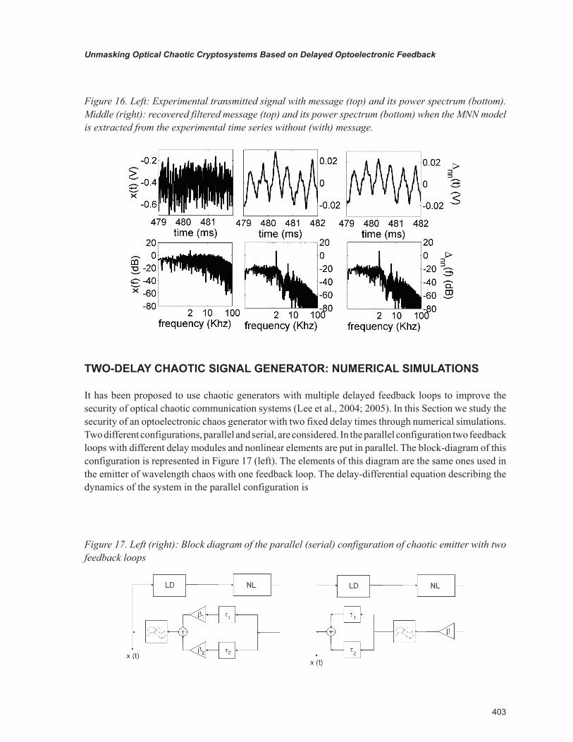
It has been proposed to use chaotic generators with multiple delayed feedback loops to improve the security of optical chaotic communication systems (Lee et al., 2004; 2005). In this Section we study the security of an optoelectronic chaos generator with two fixed delay times through numerical simulations. Two different configurations, parallel and serial, are considered. In the parallel configuration two feedback loops with different delay modules and nonlinear elements are put in parallel. The block-diagram of this configuration is represented in Figure 17 (left). The elements of this diagram are the same ones used in the emitter of wavelength chaos with one feedback loop. The delay-differential equation describing the dynamics of the system in the parallel configuration is
Figure 16. Left: Experimental transmitted signal with message (top) and its power spectrum (bottom). Middle (right): recovered filtered message (top) and its power spectrum (bottom) when the MNN model is extracted from the experimental time series without (with) message.
Figure 17. Left (right): Block diagram of the parallel (serial) configuration of chaotic emitter with two feedback loops
404
Unmasking Optical Chaotic Cryptosystems Based on Delayed Optoelectronic Feedback
x t Tdx tdt
x t x t( )( )
sin ( ) sin ( )+ = ⋅ − −
+ ⋅ − −
β τ ϕ β τ ϕ1
21 1 2
22 2
, (6)
where τ1, β1, ϕ1 and τ2, β2, ϕ2 are the delays, phase shifts, and feedback strengths, respectively, of the two feedback loops. In the serial configuration the two feedback loops have the same nonlinearity module, β1 = β2 = β (see Figure 17 right). This system can be modeled by the following equation
x t Tdx tdt
x t x t( )( )
sin ( ) ( )+ = ⋅ − + − −
β τ τ ϕ2
1 2. (7)
In this Section we use time series of x(t) obtained from numerical simulations of Eqs. (6) and (7) to reconstruct the nonlinear dynamics of two-delay chaotic carriers. We have carried out numerical simulations of Eqs. (6) and (7) for β1 = β2 = β = 15 with an integration step of 0.01. The response time is T =1 and the delay times are τ1 = 100 and τ2 = 215. The feedback phase is ϕ1 = ϕ2 = ϕ = 0.26 π. This case corresponds to a high nonlinearity with 12 extrema in the nonlinear function. A similar number of extrema is obtained in the single-delay case for a value of the normalized feedback strength greater than 25 (see Figure 6). When both delay times take similar values, the two-delay system is equivalent to the single-delay one with a feedback strength given by 2β. Ιn the following we compare the two-delay system with β1 = β2 = β = 15 to the single-delay system with a feedback strength of 30.
Time-Delay Extraction
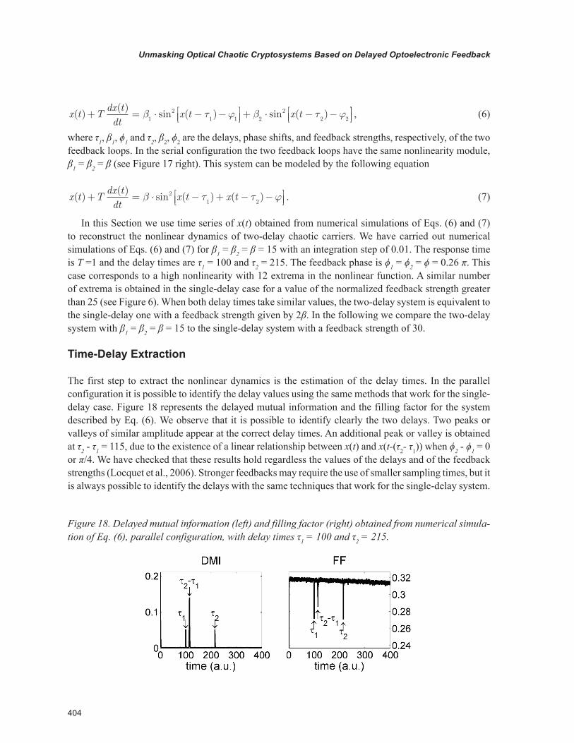
The first step to extract the nonlinear dynamics is the estimation of the delay times. In the parallel configuration it is possible to identify the delay values using the same methods that work for the single-delay case. Figure 18 represents the delayed mutual information and the filling factor for the system described by Eq. (6). We observe that it is possible to identify clearly the two delays. Two peaks or valleys of similar amplitude appear at the correct delay times. An additional peak or valley is obtained at τ2 - τ1 = 115, due to the existence of a linear relationship between x(t) and x(t-(τ2- τ1)) when ϕ2 - ϕ1 = 0 or π/4. We have checked that these results hold regardless the values of the delays and of the feedback strengths (Locquet et al., 2006). Stronger feedbacks may require the use of smaller sampling times, but it is always possible to identify the delays with the same techniques that work for the single-delay system.
Figure 18. Delayed mutual information (left) and filling factor (right) obtained from numerical simula-tion of Eq. (6), parallel configuration, with delay times τ1 = 100 and τ2 = 215.
405
Unmasking Optical Chaotic Cryptosystems Based on Delayed Optoelectronic Feedback
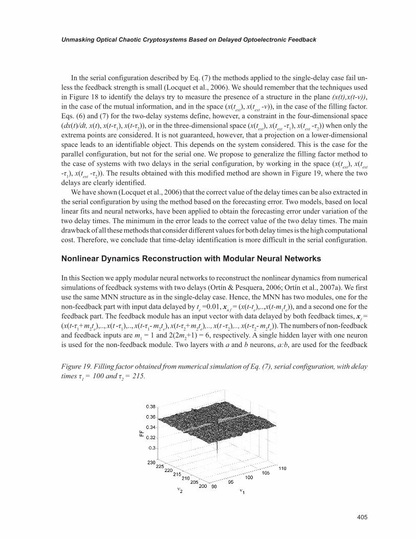
In the serial configuration described by Eq. (7) the methods applied to the single-delay case fail un-less the feedback strength is small (Locquet et al., 2006). We should remember that the techniques used in Figure 18 to identify the delays try to measure the presence of a structure in the plane (x(t),x(t-ν)), in the case of the mutual information, and in the space (x(text), x(text -ν)), in the case of the filling factor. Eqs. (6) and (7) for the two-delay systems define, however, a constraint in the four-dimensional space (dx(t)/dt, x(t), x(t-τ1), x(t-τ2)), or in the three-dimensional space (x(text), x(text -τ1), x(text -τ2)) when only the extrema points are considered. It is not guaranteed, however, that a projection on a lower-dimensional space leads to an identifiable object. This depends on the system considered. This is the case for the parallel configuration, but not for the serial one. We propose to generalize the filling factor method to the case of systems with two delays in the serial configuration, by working in the space (x(text), x(text -τ1), x(text -τ2)). The results obtained with this modified method are shown in Figure 19, where the two delays are clearly identified.
We have shown (Locquet et al., 2006) that the correct value of the delay times can be also extracted in the serial configuration by using the method based on the forecasting error. Two models, based on local linear fits and neural networks, have been applied to obtain the forecasting error under variation of the two delay times. The minimum in the error leads to the correct value of the two delay times. The main drawback of all these methods that consider different values for both delay times is the high computational cost. Therefore, we conclude that time-delay identification is more difficult in the serial configuration.
Nonlinear Dynamics Reconstruction with Modular Neural Networks
In this Section we apply modular neural networks to reconstruct the nonlinear dynamics from numerical simulations of feedback systems with two delays (Ortín & Pesquera, 2006; Ortín et al., 2007a). We first use the same MNN structure as in the single-delay case. Hence, the MNN has two modules, one for the non-feedback part with input data delayed by te =0.01, xn f = (x(t-te),..,x(t-m1te)), and a second one for the feedback part. The feedback module has an input vector with data delayed by both feedback times, xf = (x(t-τ1+m2te),.., x(t -τ1),.., x(t-τ1- m2te), x(t-τ2+m2te),.., x(t -τ2),.., x(t-τ2- m2te)). The numbers of non-feedback and feedback inputs are m1 = 1 and 2(2m2+1) = 6, respectively. A single hidden layer with one neuron is used for the non-feedback module. Two layers with a and b neurons, a:b, are used for the feedback
Figure 19. Filling factor obtained from numerical simulation of Eq. (7), serial configuration, with delay times τ1 = 100 and τ2 = 215.

406
Unmasking Optical Chaotic Cryptosystems Based on Delayed Optoelectronic Feedback
module. We take 3000 training points chosen to cover uniformly the chaotic attractor. The resulting MNN model was tested with 100000 data. In Table 1 we show the resulting normalized RMSE for both serial and parallel configurations with β1 = β2 = β =15 and delay times τ1 = 100 and τ2 = 215. These results are compared with the results obtained for the single-delay case with a feedback strength of 30 and τ = 215.
It is found that similar test errors are obtained for the two-delays serial configuration and the single-delay case. Therefore, the difficulty to extract the nonlinear dynamics is very similar in both cases. The only difference is that the number of parameters of the model is greater in the two-delay case due to the inclusion of the data delayed by the second feedback time in the input vector of the feedback module (see Table 2). However, the error obtained with one feedback module for the parallel configuration is two orders of magnitude higher than for the serial configuration and the single-delay cases. We have checked that no better results are obtained for the parallel configuration when the number of training points or the complexity of the neural network is increased (see Table 1). Adapting the MNN model to the characteristics of the parallel configuration by including a second feedback module can reduce this error. The input data for each feedback module, xfi = (x(t-τi +m2te),.., x(t -τi),.., x(t-τi- m2te)), are only delayed by the corresponding delay time τi. In this model the output of the MNN is given by xnn (t+te)=fnn (xn f) + gnn,1 (xf1)+ gnn,2 (xf2), where fnn, gnn,1 and gnn,2 correspond to the non-feedback, first and second feedback modules, respectively. The results presented in Table 1 show that the error is clearly reduced for the parallel configuration when this MNN model with two feedback modules is used. However, the number of parameters of this model increases due to the inclusion of the second feedback module (see Table 2).
Table 1. Test error of the MNN model for the single-delay system with a feedback strength of 30 and τ = 215, two-delay system in the serial and in the parallel (with one and two feedback modules) configura-tions with β1 = β2 = β = 15, τ1 = 100 and τ2 = 215. In the first column (a:b) denotes a model with hidden layers with a and b neurons for the feedback module.
MNN RMSE
NN feedback 1 delay 2 delays serial Parallel 1 module Parallel 2 modules
6: 3 2.33 10-3 2 10-3 0.015 1.7 10-3
8: 4 6.62 10-5 3.63 10-5 9.7 10-3 4.11 10-5
10: 5 6.12 10-5 3.57 10-5 4.7 10-3 2.53 10-5
12: 6 4.03 10-5 3.21 10-5 2.4 10-3 2.39 10-5
14: 7 4.03 10-5 1.74 10-5 1 10-3 1.62 10-5
Table 2. Number of parameters of the MNN model for the single-delay system, two-delay system in the serial and in the parallel (with one and two feedback modules) configurations. The parameters are the same as in Table 1.
Number of parameters
NN feedback 1 delay 2 delays serial Parallel 1 module Parallel 2 modules
6: 3 51 69 69 100
8: 4 75 99 99 148
10: 5 103 133 133 204
12: 6 135 171 171 268
14: 7 187 229 229 372
407
Unmasking Optical Chaotic Cryptosystems Based on Delayed Optoelectronic Feedback
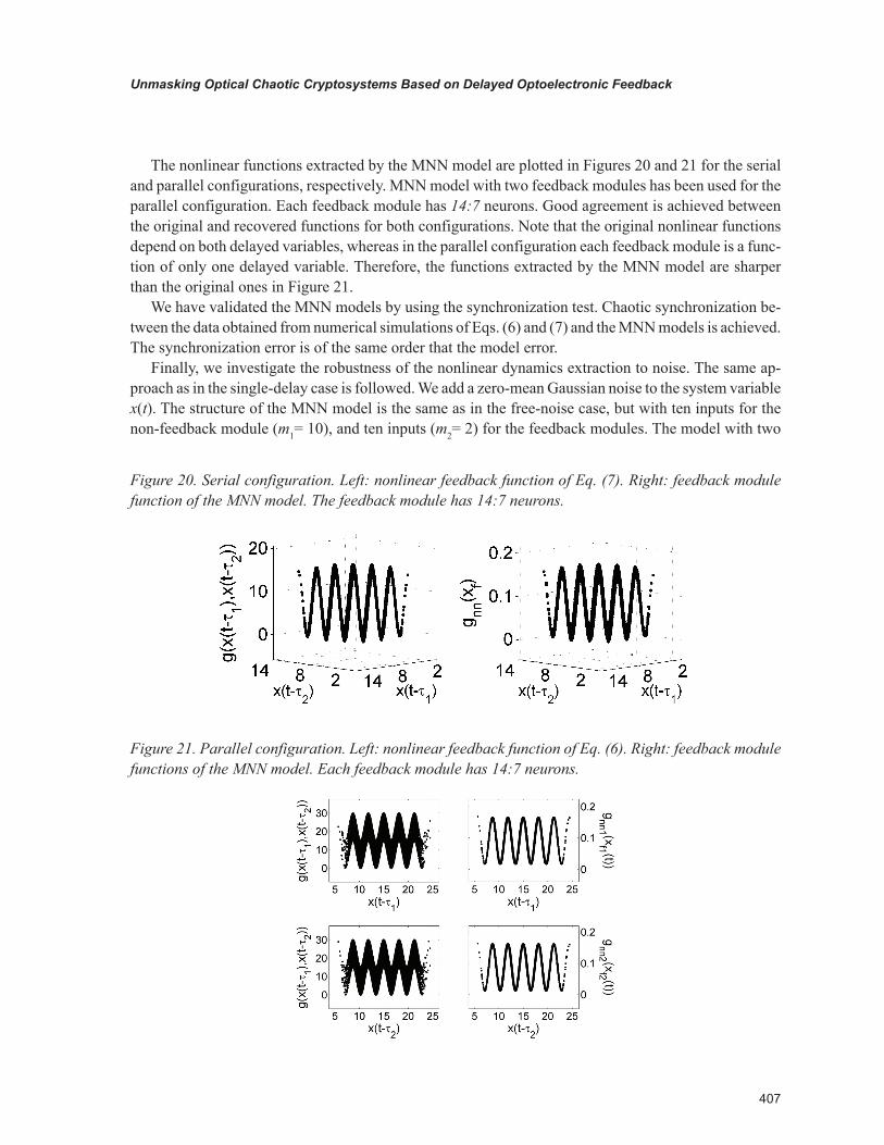
The nonlinear functions extracted by the MNN model are plotted in Figures 20 and 21 for the serial and parallel configurations, respectively. MNN model with two feedback modules has been used for the parallel configuration. Each feedback module has 14:7 neurons. Good agreement is achieved between the original and recovered functions for both configurations. Note that the original nonlinear functions depend on both delayed variables, whereas in the parallel configuration each feedback module is a func-tion of only one delayed variable. Therefore, the functions extracted by the MNN model are sharper than the original ones in Figure 21.
We have validated the MNN models by using the synchronization test. Chaotic synchronization be-tween the data obtained from numerical simulations of Eqs. (6) and (7) and the MNN models is achieved. The synchronization error is of the same order that the model error.
Finally, we investigate the robustness of the nonlinear dynamics extraction to noise. The same ap-proach as in the single-delay case is followed. We add a zero-mean Gaussian noise to the system variable x(t). The structure of the MNN model is the same as in the free-noise case, but with ten inputs for the non-feedback module (m1= 10), and ten inputs (m2= 2) for the feedback modules. The model with two
Figure 20. Serial configuration. Left: nonlinear feedback function of Eq. (7). Right: feedback module function of the MNN model. The feedback module has 14:7 neurons.
Figure 21. Parallel configuration. Left: nonlinear feedback function of Eq. (6). Right: feedback module functions of the MNN model. Each feedback module has 14:7 neurons.
408
Unmasking Optical Chaotic Cryptosystems Based on Delayed Optoelectronic Feedback
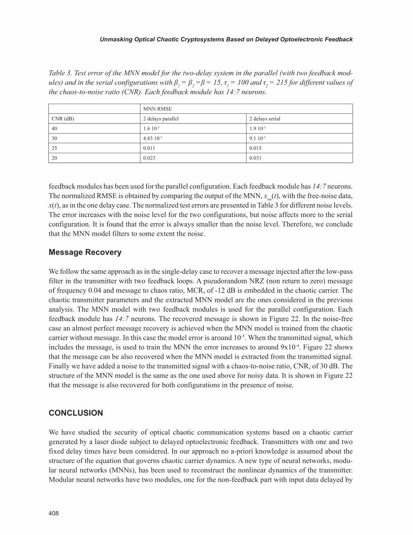
feedback modules has been used for the parallel configuration. Each feedback module has 14:7 neurons. The normalized RMSE is obtained by comparing the output of the MNN, xnn(t), with the free-noise data, x(t), as in the one delay case. The normalized test errors are presented in Table 3 for different noise levels. The error increases with the noise level for the two configurations, but noise affects more to the serial configuration. It is found that the error is always smaller than the noise level. Therefore, we conclude that the MNN model filters to some extent the noise.
Message Recovery
We follow the same approach as in the single-delay case to recover a message injected after the low-pass filter in the transmitter with two feedback loops. A pseudorandom NRZ (non return to zero) message of frequency 0.04 and message to chaos ratio, MCR, of -12 dB is embedded in the chaotic carrier. The chaotic transmitter parameters and the extracted MNN model are the ones considered in the previous analysis. The MNN model with two feedback modules is used for the parallel configuration. Each feedback module has 14:7 neurons. The recovered message is shown in Figure 22. In the noise-free case an almost perfect message recovery is achieved when the MNN model is trained from the chaotic carrier without message. In this case the model error is around 10-5. When the transmitted signal, which includes the message, is used to train the MNN the error increases to around 9x10⁻⁴. Figure 22 shows that the message can be also recovered when the MNN model is extracted from the transmitted signal. Finally we have added a noise to the transmitted signal with a chaos-to-noise ratio, CNR, of 30 dB. The structure of the MNN model is the same as the one used above for noisy data. It is shown in Figure 22 that the message is also recovered for both configurations in the presence of noise.
CONClUSION
We have studied the security of optical chaotic communication systems based on a chaotic carrier generated by a laser diode subject to delayed optoelectronic feedback. Transmitters with one and two fixed delay times have been considered. In our approach no a-priori knowledge is assumed about the structure of the equation that governs chaotic carrier dynamics. A new type of neural networks, modu-lar neural networks (MNNs), has been used to reconstruct the nonlinear dynamics of the transmitter. Modular neural networks have two modules, one for the non-feedback part with input data delayed by
Table 3. Test error of the MNN model for the two-delay system in the parallel (with two feedback mod-ules) and in the serial configurations with β1 = β2 =β = 15, τ1 = 100 and τ2 = 215 for different values of the chaos-to-noise ratio (CNR). Each feedback module has 14:7 neurons.
MNN RMSE
CNR (dB) 2 delays parallel 2 delays serial
40 1.6 10-3 1.9 10-3
30 4.83 10-3 9.1 10-3
25 0.011 0.015
20 0.023 0.031

409
Unmasking Optical Chaotic Cryptosystems Based on Delayed Optoelectronic Feedback
the embedding time, and a second one for the feedback part with input data delayed by the delay time. Nonlinear dynamics have been reconstructed from experimental time series in the single-delay case, and from numerical simulations in the one and two-delay cases. Two different configurations, serial and parallel, have been considered in the two-delay case. In the parallel configuration adapted MNNs with two feedback modules, each for one of the delay times, are required to reduce the model error. Therefore a more complex model with more parameters is needed to extract the nonlinear dynamics in the parallel configuration. We have shown that the extracted MNN model can be used in all considered cases as an unauthorized receiver to recover the message.
It is found that the complexity of the neural network required to achieve a low model error does not increase when the delay time is increased, in spite of the very high dimension of the chaotic attractor. Nonlinear dynamics of chaotic attractors with dimensions greater than 200 have been reconstructed from both experimental and numerical time series. However, it is found that nonlinear dynamics extraction is more difficult when the feedback strength is increased. These results are in agreement with the fact that the entropy increases with the feedback strength, but not with the delay time.
It is crucial to identify the delay in order to reconstruct the nonlinear dynamics of time-delay systems. Several methods have been used to extract the delay in the single-delay case. In the two-delay case with parallel configuration the delay times can be extracted with the methods used in the single-delay case. However, adapted methods with high computational cost are necessary to identify the delay times in the serial configuration.
The main conclusion of this chapter is that optical chaotic cryptosystems based on optoelectronic feedback systems with several fixed time delays are vulnerable. It has been proposed to use a variable time delay to avoid its identification by an eavesdropper, and then to enhance the security (Kye et al., 2004a). However, we have recently shown that periodic time delay functions can be extracted from experimental time series (Ortín et al., 2008). Therefore, it can be expected that the retrieval of the time
Figure 22. Top (bottom): recovered message for the serial (parallel) configuration. Right (middle): recovered message without noise when the MNN model is extracted from the time series without (with) message. Left: recovered message with noise, CNR =30 dB, when the MNN model is extracted from the time series without message.

410
Unmasking Optical Chaotic Cryptosystems Based on Delayed Optoelectronic Feedback
delay function will allow nonlinear dynamics reconstruction by working in a low-dimensional projection of the phase-space. These optoelectronic feedback systems with periodic time delay are then vulner-able. A possible way to enhance the security of these systems is to use a chaotic time delay (Kye et al., 2004b), obtained as a function of the time-delay system variable or generated by another chaotic system.
ACkNOwlEDgMENT
The authors are grateful for valuable collaboration and/or discussions to J. M. Gutiérrez, M. Jacquot, L. Larger, A. Locquet, M. Peil and A. Valle. This work was supported by CICYT (Spain) under Project TEC2009-14581-C02-02.
REfERENCES
Abarbanel, H. D. I. (1996). Analysis of Observed Chaotic Data. New York: Springer-Verlag.
Aguirre, L. A., Furtado, E. C., & Tôrres, L. A. B. (2006). Evaluation of dynamical models: dissipative synchronization and other techniques. Physical Review E: Statistical, Nonlinear, and Soft Matter Phys-ics, 74, 019612-1–16. doi:10.1103/PhysRevE.74.066203
Alvarez, G., & Li, S. (2006). Some Basic Cryptographic Requirements for Chaos-Based Cryptosystems. International Journal of Bifurcation and Chaos in Applied Sciences and Engineering, 16, 2129–2151. doi:10.1142/S0218127406015970
Argyris, A., Syvridis, D., Larger, L., Annovazzi-Lodi, V., Colet, P., & Fischer, I. (2005). Chaos-based communications at high bit rates using commercial fibre-optic links. Nature, 438, 343–346. doi:10.1038/nature04275
Ashwin, P. (2003). Synchronization from chaos. Nature, 422, 384–385. doi:10.1038/422384a
Bavard, X., Locquet, A., Larger, L., & Goedgebuer, J. P. (2007). Influence of digitisation on master–slave synchronisation in chaos-encrypted data transmission. IET Optoelectron., 1, 3–8. doi:10.1049/iet-opt:20060022
Brown, R., Rulkov, N. F., & Tracy, E. R. (1994). Modeling and synchronizing chaotic systems from time-series data. Physical Review E: Statistical Physics, Plasmas, Fluids, and Related Interdisciplinary Topics, 49, 3784–3800. doi:10.1103/PhysRevE.49.3784
Bünner, M. J., Ciofini, M., Giaquinta, A., Hegger, R., Kantz, H., Meucci, R., & Politi, A. (2000a). Re-construction of systems with delayed feedback: Theory. The European Physical Journal D, 10, 165–176. doi:10.1007/s100530050538
Bünner, M. J., Ciofini, M., Giaquinta, A., Hegger, R., Kantz, H., Meucci, R., & Politi, A. (2000b). Reconstruction of systems with delayed feedback: Application. The European Physical Journal D, 10, 177–187. doi:10.1007/s100530050539
411
Unmasking Optical Chaotic Cryptosystems Based on Delayed Optoelectronic Feedback
Bünner, M. J., Meyer, T., Kittel, A., & Parisi, J. (1997). Recovery of the time-evolution of time-delay systems from time series. Physical Review E: Statistical Physics, Plasmas, Fluids, and Related Inter-disciplinary Topics, 56, 5083–5089. doi:10.1103/PhysRevE.56.5083
Colet, P., & Roy, R. (1994). Digital communication with synchronized chaotic lasers. Optics Letters, 19, 2056–2058. doi:10.1364/OL.19.002056
Cuomo, K. M., & Oppenheim, A. V. (1993a). Circuit implementation of synchronized chaos with ap-plications to communications. IEEE Journal of Quantum Electronics, 38, 65–68.
Cuomo, K. M., Oppenheim, A. V., & Strogatz, S. H. (1993b). Synchronization of Lorenz-based chaotic circuits with applications to communications. IEEE Trans. Circuits Systems II, 40, 626-633.
Donati, S., & Mirasso, C. R. (Eds.). (2002). Feature Section on Optical Chaos and Applications to Cryptography. IEEE J. of Quantum Electron., 38.
Farmer, J. (1982). Chaotic attractors of an infinte dimenisonal system. Physica D. Nonlinear Phenomena, 4, 366–393. doi:10.1016/0167-2789(82)90042-2
Geddes, J. B., Short, K. M., & Black, K. (1999). Extraction of signals from chaotic laser data . Physical Review Letters, 83, 5389–5392. doi:10.1103/PhysRevLett.83.5389
Goedgebuer, J. P., Larger, L., & Porter, H. (1998a). Optical cryptosystem based on synchronization of hyperchaos generated by a delayed feedback tunable laser diode. Physical Review Letters, 80, 2249–2252. doi:10.1103/PhysRevLett.80.2249
Goedgebuer, J. P., Larger, L., Porter, H., & Delorme, F. (1998b). Chaos in wavelength with a feedback tunable laser diode. Physical Review E: Statistical Physics, Plasmas, Fluids, and Related Interdisciplin-ary Topics, 57, 2795–2798. doi:10.1103/PhysRevE.57.2795
Hegger, R., Bünner, M. J., Kantz, H., & Giaquinta, A. (1998). Identifying and modeling delay feedback systems. Physical Review Letters, 81, 558–561. doi:10.1103/PhysRevLett.81.558
Ikeda, K., Kondo, K., & Akimoto, O. (1982). Successive higher-harmonic bifurcations in systems with delayed feedback. Physical Review Letters, 49, 1467–1470. doi:10.1103/PhysRevLett.49.1467
Kocarev, L., Halle, K. S., Eckert, K., Chua, L. O., & Parlitz, U. (1992). Experimental demonstration of secure communications via chaotic synchronization. International Journal of Bifurcation and Chaos in Applied Sciences and Engineering, 2, 709–713. doi:10.1142/S0218127492000823
Kye, W. H., Choi, M., Kim, M. W., Lee, S. Y., Rim, S., Kim, C. M., & Park, Y. J. (2004a). Synchronization of delayed systems in the presence of delay time modulation. Physics Letters. [Part A], 322, 338–343. doi:10.1016/j.physleta.2004.01.046
Kye, W. H., Choi, M., Rim, S., Kurdoglyan, M. S., Kim, C. M., & Park, Y. J. (2004b). Characteristics of a delayed system with time-dependent delay time. Phys. Rev. E, 69, 055202(R)1-4.
Larger, L., Goedgebuer, J. P., & Delorme, F. (1998a). Optical encryption system using hyperchaos gener-ated by an optoelectronic wavelength oscillator. Physical Review E: Statistical Physics, Plasmas, Fluids, and Related Interdisciplinary Topics, 57, 6618–6624. doi:10.1103/PhysRevE.57.6618
412
Unmasking Optical Chaotic Cryptosystems Based on Delayed Optoelectronic Feedback
Larger, L., Goedgebuer, J. P., & Merolla, J. M. (1998b). Chaotic Oscillator in Wavelength: A New Setup for Investigating Differential Difference Equations Describing Nonlinear Dynamics. IEEE Journal of Quantum Electronics, 34, 594–601. doi:10.1109/3.663432
Lee, M. W., Larger, L., Udaltsov, V., Génin, E., & Goedgebuer, J. P. (2004). Demonstration of chaos generator with two delays. Optics Letters, 29, 325–327. doi:10.1364/OL.29.000325
Lee, M. W., Rees, P., Shore, K. A., Ortín, S., Pesquera, L., & Valle, A. (2005). Dynamical characterization of laser diode subject to double optical feedback for chaotic optical communications. IEE Proceedings. Optoelectronics, 152, 97–102. doi:10.1049/ip-opt:20045025
Locquet, A., Ortín, S., Udaltsov, V., Larger, L., Citrin, D. S., Pesquera, L., & Valle, A. (2006). Delay-time identification in chaotic optical systems with two delays. In D. Lenstra, M. Pessa, I. H. White (Eds.) SPIE Proceedings: Vol. 6184. Semiconductor Lasers and Laser Dynamics II. (pp. 173-184). Bellingham, WA: SPIE.
Ortín, S., Gutierrez, J. M., Pesquera, L., & Vasquez, H. (2005). Nonlinear dynamics extraction using modular neural network: synchronization and prediction. Physica A, 351, 133–141. doi:10.1016/j.physa.2004.12.015
Ortín, S., Jacquot, M., Pesquera, L., Peil, M., & Larger, L. (2007a). Nonlinear dynamics reconstruction of chaotic cryptosystems based on delayed optoelectronic feedback. In CLEO-E/IQEC (Ed.), Proceed-ings CLEO-E/IQEC(JSI1-3-THU). Munich, Germany: CLEO-E/IQEC.
Ortín, S., Jacquot, M., Pesquera, L., Peil, M., & Larger, L. (2007b). Security analysis of chaotic com-munication systems based on delayed optoelectronic feedback . In Zubia, J., Aldabaldetreku, G., Durana, G., Arrue, J., & Jiménez, F. (Eds.), Proceedings 5ª Reunión Española de Optoelectrónica (pp. 429–434). Bilbao, Spain: Escuela Técnica Superior de Ingeniería.
Ortín, S., Jacquot, M., Pesquera, L., Peil, M., & Larger, L. (2008). Time delay extraction in chaotic cryp-tosystems based on optoelectronic feedback with variable delay. In K. P. Panajotov, M. Sciamanna, A. A. Valle, R. Michalzik. (Eds.) SPIE Proceedings: Vol. 6997. Semiconductor Lasers and Laser Dynamics III. (pp. 69970E-1-12). Bellingham, WA: SPIE.
Ortín, S., & Pesquera, L. (2006). Cracking Chaos-based Encryption Systems Based on Laser Diodes with Optoelectronic Feedback with Two Delays. In D. Lenstra, J. M. Dudley, J. Rarity, C. R. Mirasso (Eds.), Proceedings ECOC: Vol. 6. CLEO Focus meeting (Tu3_1_2, pp. 15-16). Cannes, France: Euro-pean Conference on Optical Communications.
Ortín, S., Pesquera, L., Gutiérrez, J. M., Valle, A., & Cofiño, A. (2007c). Nonlinear dynamics reconstruc-tion with neural networks of chaotic communication time-delay systems. In J. Marro, P. L. Garrido, J. J. Torres (Eds.), AIP Proceedings: Vol. 887. Cooperative Behavior in Neural Systems. (pp. 249-258). New York: American Institute of Physics.
Perez, G., & Cerdeira, H. (1995). Extracting messages masked by chaos. Physical Review Letters, 74, 1970–1073. doi:10.1103/PhysRevLett.74.1970

413
Unmasking Optical Chaotic Cryptosystems Based on Delayed Optoelectronic Feedback
Ponomarenko, V. I., & Prokhorov, M. D. (2002). Extracting information masked by the chaotic signal of a time-delay system. Physical Review E: Statistical, Nonlinear, and Soft Matter Physics, 66, 026215-1–7. doi:10.1103/PhysRevE.66.026215
Press, W. H., Flannery, B. P., Teukolsky, S. A., & Vetterling, W. T. (1992). Numerical Recipes. Cambridge, UK: Cambridge University Press.
Principe, J. C., Rathie, A., & Kuo, J. M. (1992). Prediction of chaotic time series with neural networks and the issue of dynamic modelling. International Journal of Bifurcation and Chaos in Applied Sciences and Engineering, 2, 989–996. doi:10.1142/S0218127492000598
Robilliard, C., Huntington, E. H., & Webb, J. G. (2006). Enhancing the Security of Delayed Differential Chaotic Systems With Programmable Feedback. IEEE Transactions on Circuits and Wystems. II, Express Briefs, 53, 722–726. doi:10.1109/TCSII.2006.876405
Rulkov, N. F., Sushckik, M. M., Tsimring, L. S., & Abarbanel, H. D. I. (1995). Generalized syncroniza-tion of chaos in directionally coupled chaotic systems. Physical Review E: Statistical Physics, Plasmas, Fluids, and Related Interdisciplinary Topics, 51, 980–994. doi:10.1103/PhysRevE.51.980
Short, K. M. (1994). Steps toward unmasking secure communications. International Journal of Bifurca-tion and Chaos in Applied Sciences and Engineering, 4, 959–977. doi:10.1142/S021812749400068X
Short, K. M. (1996). Unmasking a modulated chaotic communications scheme. International Journal of Bifurcation and Chaos in Applied Sciences and Engineering, 6, 367–375. doi:10.1142/S0218127496000114
Short, K. M., & Parker, A. T. (1998). Unmasking a hyperchaotic communication scheme. Physical Review E: Statistical Physics, Plasmas, Fluids, and Related Interdisciplinary Topics, 58, 1159–1162. doi:10.1103/PhysRevE.58.1159
Tenny, R., & Tsimring, L. S. (2004). Steps towards cryptanalysis of chaotic active/passive decomposition encryption schemes using average dynamics estimation. International Journal of Bifurcation and Chaos in Applied Sciences and Engineering, 14, 3949–3968. doi:10.1142/S0218127404011727
Uchida, A., Rogister, F., García-Ojalvo, J., & Roy, R. (2005). Synchronization and communication with chaotic laser systems . In Wolf, E. (Ed.), Progress in Optics (Vol. 48, pp. 203–341). Amsterdam, The Netherlands: Elsevier B. V.
Udaltsov, V. S., Goedgebuer, J. P., Larger, L., Cuenot, J. B., Levy, P., & Rhodes, W. T. (2003). Cracking chaos-based encryption systems ruled by nonlinear delay differential equations. Physics Letters. [Part A], 308, 54–60. doi:10.1016/S0375-9601(02)01776-0
Vicente, R., Daudén, J., Colet, P., & Toral, R. (2005). Analysis and Characterization of the Hyperchaos Generated by a Semiconductor Laser Subject to a Delayed Feedback Loop. IEEE Journal of Quantum Electronics, 41, 541–548. doi:10.1109/JQE.2005.843606
Yang, T., Yang, L. B., & Yang, C. M. (1998a). Breaking chaotic secure communication using a spectro-gram. Physics Letters. [Part A], 247, 105–111. doi:10.1016/S0375-9601(98)00560-X
Yang, T., Yang, L. B., & Yang, C. M. (1998b). Breaking chaotic switching using generalized synchro-nization: Examples. IEEE Trans. Circuits and Systems I, 45, 1062-1067.
414
Unmasking Optical Chaotic Cryptosystems Based on Delayed Optoelectronic Feedback
Zhou, C., & Lai, C. (1999). Extracting messages masked by chaotic signals of time-delay systems. Physi-cal Review E: Statistical Physics, Plasmas, Fluids, and Related Interdisciplinary Topics, 60, 320–323. doi:10.1103/PhysRevE.60.320
kEy TERMS AND DEfINITIONS
Chaotic Communication Systems: Communication systems that use a chaotic carrier.Synchronization: Phenomenon by which two coupled systems starting from different initial condi-
tions follow the same trajectory after a transient.Time-Delay Systems: Dynamical systems whose evolution depends of a delayed value of the system
variable.Feedback: Describes the situation when output from an event or phenomenon in the past will influ-
ence the same event/phenomenon in the future.Artificial Neural Network: A model based on biological neural networks. It consists of an intercon-
nected group of artificial neurons and processes information using a connectionist approach to computa-tion. The network behaviour is stored in the connections between neurons in values called weights, which represent the strength of each link. In most cases an artificial neural network is an adaptive system that changes its structure based on external or internal information that flows through the network during the learning phase.
Related Documents