Channel and Bolt Fixings for the Construction Industry CI/SfB (21.9) Xt6 July 2013

Welcome message from author
This document is posted to help you gain knowledge. Please leave a comment to let me know what you think about it! Share it to your friends and learn new things together.
Transcript
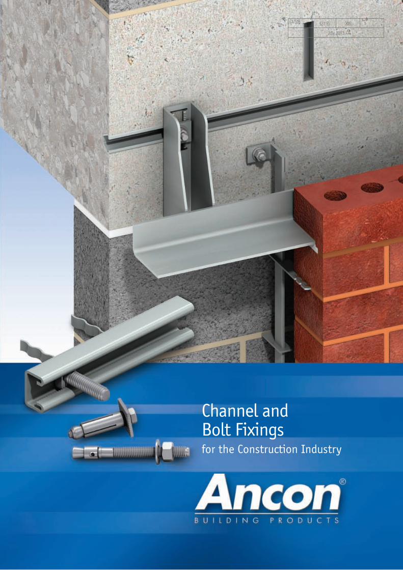
Channel and Bolt Fixings for the Construction Industry
CI/SfB (21.9) Xt6
July 2013
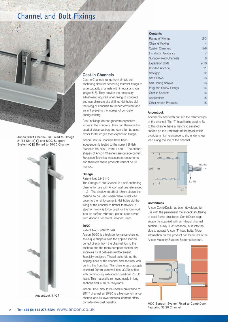
Cast-in ChannelsCast-in Channels range from simple self-anchoring slots for accepting restraint fixings tolarge capacity channels with integral anchors(pages 5-6). They provide the necessaryadjustment required when fixing to concreteand can eliminate site drilling. Nail holes aidthe fixing of channels to timber formwork andan infill prevents the ingress of concrete during casting.
Cast-in fixings do not generate expansiveforces in the concrete. They can therefore beused at close centres and can often be usedcloser to the edges than expansion fixings.
Ancon Cast-in Channels have beenindependently tested to the current BritishStandard BS 5080, Parts 1 and 2. The anchorshapes of Ancon Channels are outside currentEuropean Technical Assessment documentsand therefore these products cannot be CEmarked.
OmegaPatent No: 2249110The Omega 21/18 Channel is a self-anchoringchannel for use with Ancon wall ties referenced _ _21. The shallow depth of 18mm allows thechannel to be used where there is reducedcover to the reinforcement. Nail holes aid thefixing of the channel to timber formwork. Ifsteel formwork is to be used, or the formworkis to be surface-vibrated, please seek advicefrom Ancon’s Technical Services Team.
30/20Patent No: EP0882164BAncon 30/20 is a high performance channel.Its unique shape allows the applied load to be fed directly from the channel lips to theanchors and the more compact section sizeimproves its fit between reinforcement.Specially designed T-head bolts ride up thesloping sides of the channel and securely lockbehind the front lips. This channel also acceptsstandard 20mm wide wall ties. 30/20 is filledwith continuously extruded closed-cell PE-LDfoam. This material is removed easily in longsections and is 100% recyclable.
Ancon 30/20 should be used in preference to38/17 channel as 30/20 is a high performancechannel and its lower material content offersconsiderable cost benefits. MDC Support System Fixed to CombiDeck
Featuring 30/20 Channel
AnconLockAnconLock has teeth cut into the returned lipsof the channel. The ‘T’ head bolts used to fixto this channel have a matching serratedsurface on the underside of the head whichprovides a high resistance to slip under shearload along the line of the channel.
CombiDeckAncon CombiDeck has been developed foruse with the permanent metal deck shutteringof steel frame structures. CombiDeck edgesupport is supplied with an integral channelsection, usually 30/20 channel, built into theside to accept Ancon ‘T’ head bolts. Moreinformation on this product can be found in theAncon Masonry Support Systems literature.
15.3 kN
15
70
27
100
158.1 kN
AnconLock 41/27
Ancon SD21 Channel Tie Fixed to Omega21/18 Slot ( ) and MDC SupportSystem ( ) Bolted to 30/20 Channel
Contents
Range of Fixings 2-3
Channel Profiles 4
Cast-in Channels 5-6
Installation Guidance 7
Surface-Fixed Channels 8
Expansion Bolts 9-10
Bonded Anchors 11
Steelgrip 12
Set Screws 13
Self-Drilling Screws 13
Plug and Screw Fixings 14
Cast-in Sockets 14
Applications 15
Other Ancon Products 15
2 Tel: +44 (0) 114 275 5224 www.ancon.co.uk
Channel and Bolt Fixings
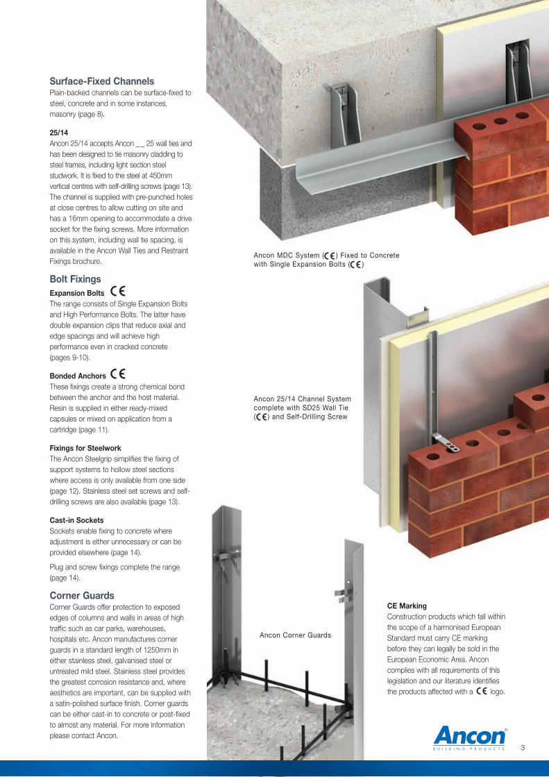
Surface-Fixed Channels Plain-backed channels can be surface-fixed tosteel, concrete and in some instances,masonry (page 8).
25/14Ancon 25/14 accepts Ancon _ _ 25 wall ties andhas been designed to tie masonry cladding tosteel frames, including light section steelstudwork. It is fixed to the steel at 450mmvertical centres with self-drilling screws (page 13).The channel is supplied with pre-punched holesat close centres to allow cutting on site andhas a 16mm opening to accommodate a drivesocket for the fixing screws. More informationon this system, including wall tie spacing, isavailable in the Ancon Wall Ties and RestraintFixings brochure.
Bolt FixingsExpansion BoltsThe range consists of Single Expansion Boltsand High Performance Bolts. The latter havedouble expansion clips that reduce axial andedge spacings and will achieve highperformance even in cracked concrete (pages 9-10).
Bonded AnchorsThese fixings create a strong chemical bondbetween the anchor and the host material.Resin is supplied in either ready-mixedcapsules or mixed on application from acartridge (page 11).
Fixings for SteelworkThe Ancon Steelgrip simplifies the fixing ofsupport systems to hollow steel sectionswhere access is only available from one side(page 12). Stainless steel set screws and self-drilling screws are also available (page 13).
Cast-in SocketsSockets enable fixing to concrete whereadjustment is either unnecessary or can beprovided elsewhere (page 14).
Plug and screw fixings complete the range(page 14).
Corner GuardsCorner Guards offer protection to exposededges of columns and walls in areas of hightraffic such as car parks, warehouses,hospitals etc. Ancon manufactures cornerguards in a standard length of 1250mm ineither stainless steel, galvanised steel oruntreated mild steel. Stainless steel providesthe greatest corrosion resistance and, whereaesthetics are important, can be supplied witha satin-polished surface finish. Corner guardscan be either cast-in to concrete or post-fixedto almost any material. For more informationplease contact Ancon.
CE MarkingConstruction products which fall withinthe scope of a harmonised EuropeanStandard must carry CE markingbefore they can legally be sold in theEuropean Economic Area. Anconcomplies with all requirements of thislegislation and our literature identifiesthe products affected with a logo.
Ancon MDC System ( ) Fixed to Concretewith Single Expansion Bolts ( )
Ancon 25/14 Channel Systemcomplete with SD25 Wall Tie( ) and Self-Drilling Screw
Ancon Corner Guards
3
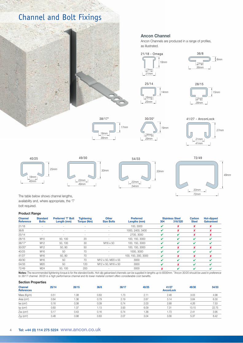
Ancon ChannelAncon Channels are produced in a range of profiles,as illustrated.
25/14
14mm
Channel Standard Preferred ‘T’ Bolt Tightening Other Preferred Stainless Steel Carbon Hot-dippedReference Bolts Length (mm) Torque (Nm) Size Bolts Lengths (mm) 304 316/320 Steel Galvanised
21/18 - - - - 100, 3000
36/8 - - - - 1000, 2400, 3400
25/14 - - - - 2700, 3000
28/15 M10 50, 100 20 - 100, 150, 3000
38/17* M12 50, 100 30 M16 x 50 100, 150, 3000
30/20* M12 50, 90 50 - 100, 150, 3000
40/25 M16 50 70 - 1000, 3000
41/27 M16 50, 80 70 - 100, 150, 200, 3000
49/30 M16 50 70 M12 x 50, M20 x 55 3000
54/33 M20 50 120 M12 x 50, M16 x 50 3000
72/49 M24 50, 100 200 - 3000
Notes: The recommended tightening torque is for the standard bolts. Hot-dip galvanised channels can be supplied in lengths up to 6000mm. *Ancon 30/20 should be used in preferenceto 38/17 channel. 30/20 is a high performance channel and its lower material content offers considerable cost benefits.
✔ ✘ ✘ ✘
✔ ✘ ✘ ✘
✔ ✔ ✘ ✘
✔ ✔ ✔ ✔
✔ ✔ ✔ ✔
✔ ✘ ✘ ✘
✔ ✔ ✔ ✔
✔ ✘ ✘ ✘
✔ ✔ ✔ ✔
✔ ✘ ✔ ✔
✘ ✔ ✔ ✔
21/18 - Omega 36/8
28/15
30/20* 41/27 - AnconLock
40/25 49/30 54/33 72/49
38/17*
13mm
18mm
21mm
14mm
19mm
29mm 21mm
27mm
41mm
22mm
30mm
49mm22mm
33mm
54mm33mm
49mm
72mm
18mm
25mm
40mm
12mm
15mm
28mm
18mm
17mm
38mm
12mm
8mm
36mm
Channel and Bolt Fixings
25mm
16mm
The table below shows channel lengths,availability and, where appropriate, the ‘T’ bolt required.
Channel 25/14 28/15 36/8 38/17 40/25 41/27 49/30 54/33References AnconLock
Mass (Kg/m) 0.51 1.08 0.63 1.73 2.11 2.48 3.03 4.98
Area (cm2) 0.64 1.36 0.79 2.19 2.67 3.14 3.84 6.30
Ixx (cm4) 0.16 0.38 0.09 0.74 2.03 2.68 4.26 7.53
Iyy (cm4) 0.60 1.37 1.13 3.93 6.09 7.31 13.15 22.75
Zxx (cm3) 0.17 0.43 0.16 0.74 1.38 1.73 2.41 3.95
Zyy (cm3) 0.48 0.98 0.63 2.07 3.04 3.56 5.37 8.42
4 Tel: +44 (0) 114 275 5224 www.ancon.co.uk
Product Range
Section Properties
Thickness
Length Spacing
Spacing
Width
Centres
Thickness
Length
SpacingReturn
SpacingWidth
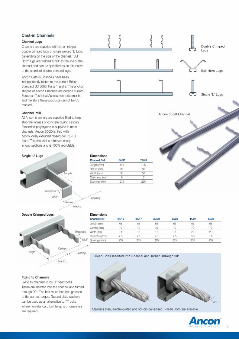
Double Crimped Lugs
Single 'L' Lugs
Double CrimpedLugs
Bull Horn Lugs
Single ‘L’ Lugs
DimensionsChannel Ref 28/15 38/17 30/20 40/25 41/27 49/30
Length (mm) 65 65 65 65 65 65
Centres (mm) 70 70 70 70 70 70
Width (mm) 11 15 11 15 20 20
Thickness (mm) 2.5 2.5 2.5 2.5 3.0 3.0
Spacings (mm) 235 235 220 235 235 235
Channel Ref 54/33 72/49
Length (mm) 120 125
Return (mm) 35 35
Width (mm) 30 50
Thickness (mm) 6 6
Spacings (mm) 235 235
Dimensions
Cast-in ChannelsChannel LugsChannels are supplied with either integraldouble crimped lugs or single welded ‘L’ lugs,depending on the size of the channel. ‘BullHorn’ lugs are welded at 90° to the line of thechannel and can be specified as an alternativeto the standard double crimped lugs.
Ancon Cast-in Channels have beenindependently tested to the current BritishStandard BS 5080, Parts 1 and 2. The anchorshapes of Ancon Channels are outside currentEuropean Technical Assessment documentsand therefore these products cannot be CEmarked.
Channel InfillAll Ancon channels are supplied filled to helpstop the ingress of concrete during casting.Expanded polystyrene is supplied in mostchannels. Ancon 30/20 is filled withcontinuously extruded closed-cell PE-LD foam. This material is removed easilyin long sections and is 100% recyclable.
Ancon 30/20 Channel
Fixing to ChannelsFixing to channels is by ‘T’ head bolts. These are inserted into the channel and turnedthrough 90°. The bolt must then be tightenedto the correct torque. Tapped plate washerscan be used as an alternative to ‘T’ boltswhere non-standard bolt lengths or diametersare required.
90°
T-Head Bolts Inserted into Channel and Turned Through 90°
Stainless steel, electro-plated and hot-dip galvanised T-Head Bolts are available.
5
Channel and Bolt Fixings
ChannelSpacing
EndDistance
ConcreteDepth
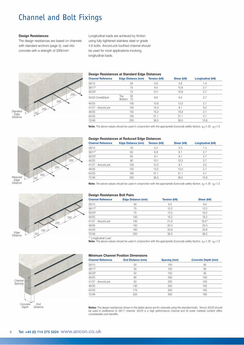
Channel Reference Edge Distance (mm) Tension (kN) Shear (kN)
28/15 50 9.5 9.5
38/17* 75 12.2 12.2
30/20* 75 13.5 16.2
40/25 100 16.2 16.2
41/27 - AnconLock 100 21.6 18.4**
49/30 150 20.3 20.3
54/33 160 33.8 33.8
72/49 250 36.5 36.5** Longitudinal LoadNote: The above values should be used in conjunction with the appropriate Eurocode safety factors. gG=1.35 gQ=1.5
Channel Reference End Distance (mm) Spacing (mm) Concrete Depth (mm)
28/15 50 100 95
38/17* 50 150 95
30/20* 50 150 95
40/25 80 200 100
41/27 - AnconLock 50 200 100
49/30 130 300 105
54/33 175 320 165
72/49 225 500 185
Notes: The design resistances shown in the tables above are for channels using the standard bolts. *Ancon 30/20 shouldbe used in preference to 38/17 channel. 30/20 is a high performance channel and its lower material content offersconsiderable cost benefits.
50100
50Standard
EdgeDistance
200
200
200
50ReducedEdge
Distance
200
200
200
EdgeDistance
200
100
Design ResistancesThe design resistances are based on channelswith standard anchors (page 5), cast intoconcrete with a strength of 30N/mm2.
Longitudinal loads are achieved by frictionusing fully-tightened stainless steel or grade4.6 bolts. AnconLock toothed channel shouldbe used for most applications involvinglongitudinal loads.
Channel Reference Edge Distance (mm) Tension (kN) Shear (kN) Longitudinal (kN)
28/15 50 5.8 5.8 1.4
38/17* 75 9.5 10.8 2.7
30/20* 75 10.1 10.8 2.7
30/20 CombiDeck Top 55 8.8 9.5 2.7Bottom 75
40/25 100 10.8 13.5 2.7
41/27 - AnconLock 100 15.3 8.1 9.2
49/30 150 16.2 18.9 2.7
54/33 160 31.1 31.1 4.1
72/49 250 36.5 36.5 10.8
Note: The above values should be used in conjunction with the appropriate Eurocode safety factors. gG=1.35 gQ=1.5
Channel Reference Edge Distance (mm) Tension (kN) Shear (kN) Longitudinal (kN)
28/15 40 5.4 5.4 1.4
38/17* 60 6.8 8.1 2.7
30/20* 60 8.1 8.1 2.7
40/25 80 10.1 12.2 2.7
41/27 - AnconLock 100 15.3 8.1 9.2
49/30 120 13.5 13.5 2.7
54/33 160 31.1 31.1 4.1
72/49 250 36.5 36.5 10.8
Note: The above values should be used in conjunction with the appropriate Eurocode safety factors. gG=1.35 gQ=1.5
Design Resistances at Standard Edge Distances
Design Resistances at Reduced Edge Distances
Design Resistances Bolt Pairs
Minimum Channel Position Dimensions
6 Tel: +44 (0) 114 275 5224 www.ancon.co.uk
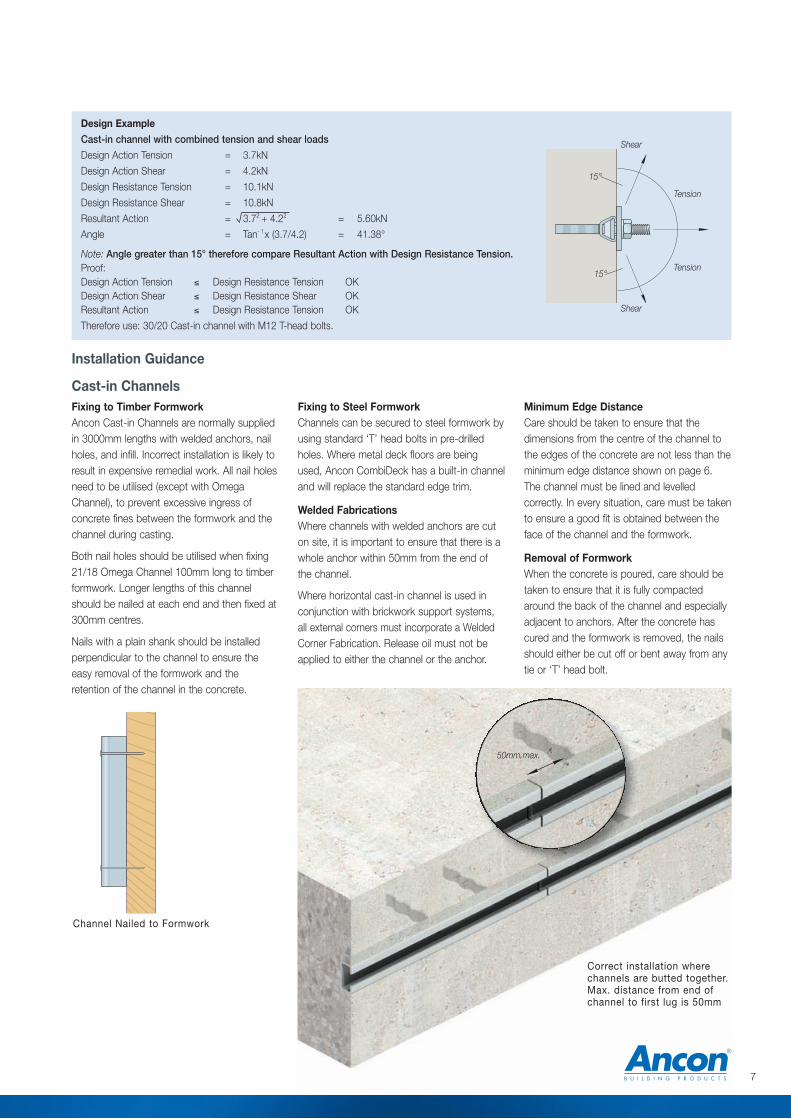
Correct installation wherechannels are butted together.Max. distance from end ofchannel to first lug is 50mm
Fixing to Steel FormworkChannels can be secured to steel formwork byusing standard ‘T’ head bolts in pre-drilledholes. Where metal deck floors are beingused, Ancon CombiDeck has a built-in channeland will replace the standard edge trim.
Welded FabricationsWhere channels with welded anchors are cuton site, it is important to ensure that there is awhole anchor within 50mm from the end of the channel.
Where horizontal cast-in channel is used inconjunction with brickwork support systems,all external corners must incorporate a WeldedCorner Fabrication. Release oil must not beapplied to either the channel or the anchor.
Installation Guidance
Cast-in ChannelsFixing to Timber FormworkAncon Cast-in Channels are normally suppliedin 3000mm lengths with welded anchors, nailholes, and infill. Incorrect installation is likely toresult in expensive remedial work. All nail holesneed to be utilised (except with OmegaChannel), to prevent excessive ingress ofconcrete fines between the formwork and thechannel during casting.
Both nail holes should be utilised when fixing21/18 Omega Channel 100mm long to timberformwork. Longer lengths of this channelshould be nailed at each end and then fixed at300mm centres.
Nails with a plain shank should be installedperpendicular to the channel to ensure theeasy removal of the formwork and theretention of the channel in the concrete.
Channel Nailed to Formwork
Design Example Cast-in channel with combined tension and shear loads
Design Action Tension = 3.7kN
Design Action Shear = 4.2kN
Design Resistance Tension = 10.1kN
Design Resistance Shear = 10.8kN
Resultant Action = 3.72 + 4.22 = 5.60kN
Angle = Tan- 1x (3.7/4.2) = 41.38°
Note: Angle greater than 15° therefore compare Resultant Action with Design Resistance Tension.Proof:Design Action Tension ≤ Design Resistance Tension OKDesign Action Shear ≤ Design Resistance Shear OKResultant Action ≤ Design Resistance Tension OK
Therefore use: 30/20 Cast-in channel with M12 T-head bolts.
50mm max.
Minimum Edge DistanceCare should be taken to ensure that thedimensions from the centre of the channel tothe edges of the concrete are not less than theminimum edge distance shown on page 6.The channel must be lined and levelledcorrectly. In every situation, care must be takento ensure a good fit is obtained between theface of the channel and the formwork.
Removal of FormworkWhen the concrete is poured, care should betaken to ensure that it is fully compactedaround the back of the channel and especiallyadjacent to anchors. After the concrete hascured and the formwork is removed, the nailsshould either be cut off or bent away from anytie or ‘T’ head bolt.
Shear
Shear
15°
15°
Tension
Tension
7
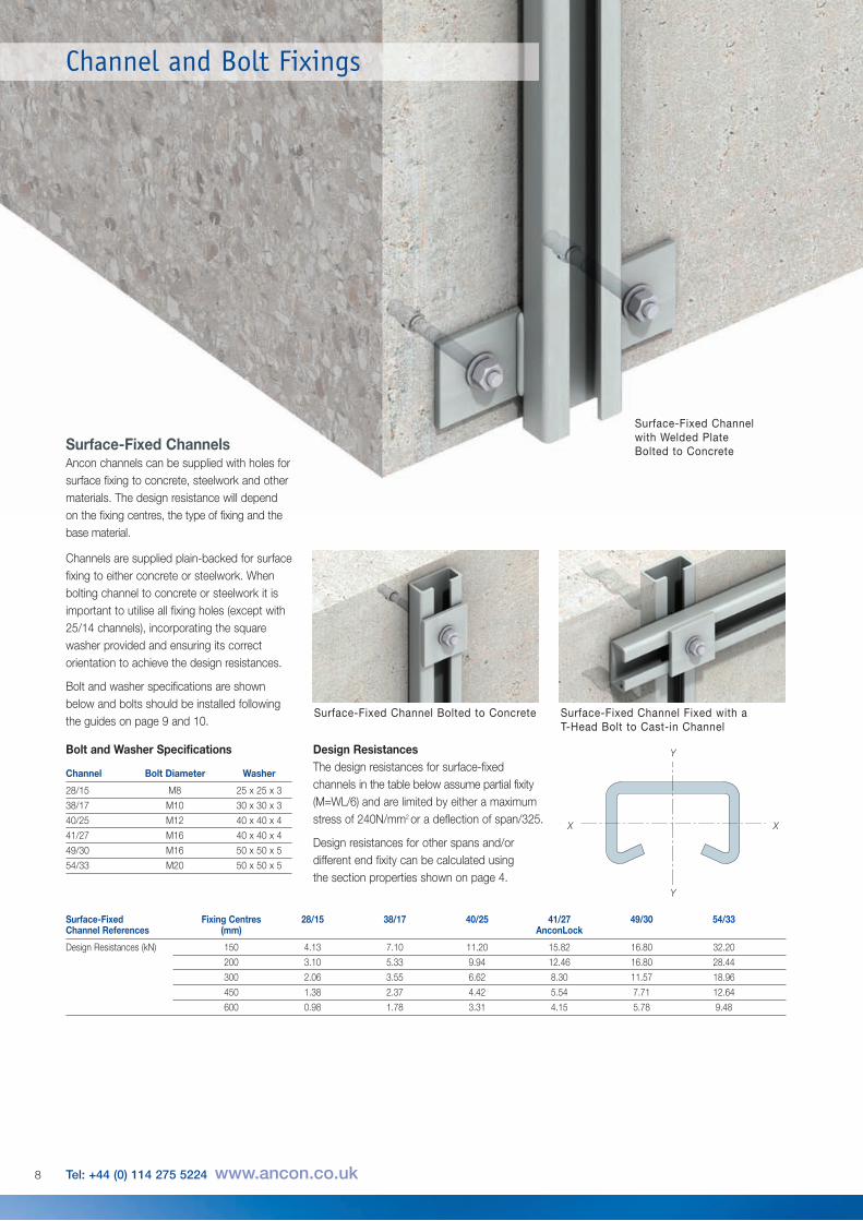
Surface-Fixed ChannelsAncon channels can be supplied with holes forsurface fixing to concrete, steelwork and othermaterials. The design resistance will dependon the fixing centres, the type of fixing and thebase material.
Channels are supplied plain-backed for surfacefixing to either concrete or steelwork. Whenbolting channel to concrete or steelwork it isimportant to utilise all fixing holes (except with25/14 channels), incorporating the squarewasher provided and ensuring its correctorientation to achieve the design resistances.
Bolt and washer specifications are shownbelow and bolts should be installed followingthe guides on page 9 and 10.
Design ResistancesThe design resistances for surface-fixedchannels in the table below assume partial fixity(M=WL/6) and are limited by either a maximumstress of 240N/mm2 or a deflection of span/325.
Design resistances for other spans and/ordifferent end fixity can be calculated using the section properties shown on page 4.
Surface-Fixed Fixing Centres 28/15 38/17 40/25 41/27 49/30 54/33Channel References (mm) AnconLock
Design Resistances (kN) 150 4.13 7.10 11.20 15.82 16.80 32.20
200 3.10 5.33 9.94 12.46 16.80 28.44
300 2.06 3.55 6.62 8.30 11.57 18.96
450 1.38 2.37 4.42 5.54 7.71 12.64
600 0.98 1.78 3.31 4.15 5.78 9.48
Y
XX
Y
Surface-Fixed Channel Bolted to Concrete Surface-Fixed Channel Fixed with a T-Head Bolt to Cast-in Channel
Surface-Fixed Channelwith Welded PlateBolted to Concrete
Channel and Bolt Fixings
Bolt and Washer Specifications
Channel Bolt Diameter Washer
28/15 M8 25 x 25 x 3
38/17 M10 30 x 30 x 3
40/25 M12 40 x 40 x 4
41/27 M16 40 x 40 x 4
49/30 M16 50 x 50 x 5
54/33 M20 50 x 50 x 5
8 Tel: +44 (0) 114 275 5224 www.ancon.co.uk
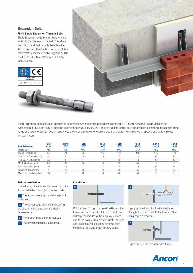
Expansion BoltsFBNII Single Expansion Through BoltsSingle Expansion bolts fix into a hole which issimilar to the diameter of the bolt. This allowsthe hole to be drilled through the hole in theitem to be fixed. The Single Expansion bolt is acost-effective anchor, available in grade A4 316(1.4401 or 1.4571) stainless steel in a widerange of sizes.
Before InstallationThe following checks must be carried out priorto the installation of Single Expansion Bolts.
The appropriate length and diameter drillbit is used.
The correct edge distance and spacingare used in accordance with the designrequirements.
The anchor/fixing is the correct size.
The correct setting tools are used.
Installation
Lightly tap the throughbolt with a hammerthrough the fixture and into the hole, until thefixing depth is reached.
Drill the hole, through the pre-drilled hole in thefixture, into the concrete. This hole should bedrilled perpendicular to the substrate surface,and to the correct diameter and depth. All dustand loose material should be removed fromthe hole using a wire brush or blow pump.
5 6
Tighten bolt to the recommended torque.
7
1
2
3
4
FBNII Expansion Bolts should be specified in accordance with the design procedures described in ETAG001 Annex C: Design Methods forAnchorages. FBNII bolts carry a European Technical Approval (ETA-07/0211) and are suitable for use in un-cracked concrete within the strength classrange of C20/25 to C50/60. Design resistances should be calculated for each individual application. For guidance on specific applications pleasecontact Ancon.
FBNII FBNII FBNII FBNII FBNII FBNII FBNII FBNIIBolt Reference 6/10 8/10 10/20 10/50 12/20 12/50 16/25 16/50Thread Size M6 M8 M10 M10 M12 M12 M16 M16
Overall Length (mm) 55 71 96 126 116 146 145 170
Hole Dia. In Concrete (mm) 6 8 10 10 12 12 16 16
Hole Dia. in Fixture (mm) 6.5 9 11 11 13 13 17 17
Min. Embedment (mm) 30 40 50 50 65 65 80 80
Width Across Nut (mm) 10 13 17 17 19 19 24 24
Tightening Torque (Nm) 4 10 20 20 35 35 80 80
Max. Fixing Thickness (mm) 10 10 20 50 20 50 25 50
ETA-07/0211ETAG 001- 2
Option 7 for non-cracked concrete
9
Channel and Bolt Fixings
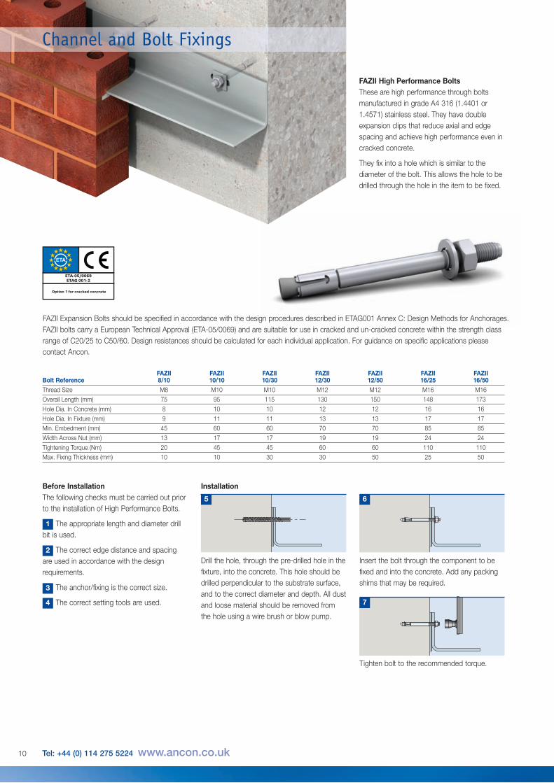
FAZII High Performance BoltsThese are high performance through boltsmanufactured in grade A4 316 (1.4401 or1.4571) stainless steel. They have doubleexpansion clips that reduce axial and edgespacing and achieve high performance even incracked concrete.
They fix into a hole which is similar to thediameter of the bolt. This allows the hole to bedrilled through the hole in the item to be fixed.
FAZII Expansion Bolts should be specified in accordance with the design procedures described in ETAG001 Annex C: Design Methods for Anchorages.FAZII bolts carry a European Technical Approval (ETA-05/0069) and are suitable for use in cracked and un-cracked concrete within the strength classrange of C20/25 to C50/60. Design resistances should be calculated for each individual application. For guidance on specific applications pleasecontact Ancon.
2
3
4
Before InstallationThe following checks must be carried out priorto the installation of High Performance Bolts.
The appropriate length and diameter drillbit is used.
The correct edge distance and spacingare used in accordance with the designrequirements.
The anchor/fixing is the correct size.
The correct setting tools are used.
Installation
Insert the bolt through the component to befixed and into the concrete. Add any packingshims that may be required.
Drill the hole, through the pre-drilled hole in thefixture, into the concrete. This hole should bedrilled perpendicular to the substrate surface,and to the correct diameter and depth. All dustand loose material should be removed fromthe hole using a wire brush or blow pump.
5 6
Tighten bolt to the recommended torque.
7
1
FAZII FAZII FAZII FAZII FAZII FAZII FAZII Bolt Reference 8/10 10/10 10/30 12/30 12/50 16/25 16/50Thread Size M8 M10 M10 M12 M12 M16 M16
Overall Length (mm) 75 95 115 130 150 148 173
Hole Dia. In Concrete (mm) 8 10 10 12 12 16 16
Hole Dia. In Fixture (mm) 9 11 11 13 13 17 17
Min. Embedment (mm) 45 60 60 70 70 85 85
Width Across Nut (mm) 13 17 17 19 19 24 24
Tightening Torque (Nm) 20 45 45 60 60 110 110
Max. Fixing Thickness (mm) 10 10 30 30 50 25 50
ETA-05/0069ETAG 001- 2
Option 1 for cracked concrete
10 Tel: +44 (0) 114 275 5224 www.ancon.co.uk
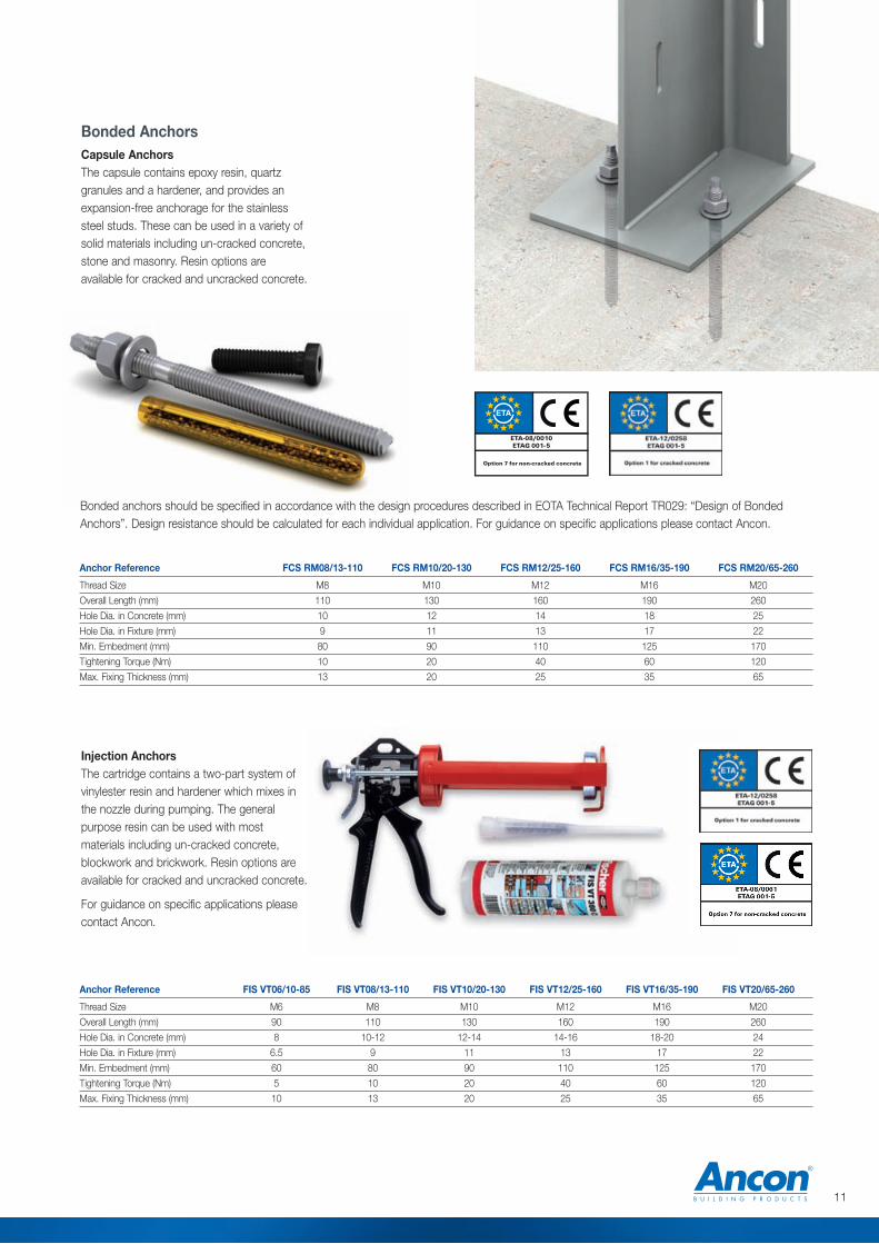
Bonded AnchorsCapsule AnchorsThe capsule contains epoxy resin, quartzgranules and a hardener, and provides anexpansion-free anchorage for the stainlesssteel studs. These can be used in a variety ofsolid materials including un-cracked concrete,stone and masonry. Resin options areavailable for cracked and uncracked concrete.
Anchor Reference FCS RM08/13-110 FCS RM10/20-130 FCS RM12/25-160 FCS RM16/35-190 FCS RM20/65-260
Thread Size M8 M10 M12 M16 M20
Overall Length (mm) 110 130 160 190 260
Hole Dia. in Concrete (mm) 10 12 14 18 25
Hole Dia. in Fixture (mm) 9 11 13 17 22
Min. Embedment (mm) 80 90 110 125 170
Tightening Torque (Nm) 10 20 40 60 120
Max. Fixing Thickness (mm) 13 20 25 35 65
Anchor Reference FIS VT06/10-85 FIS VT08/13-110 FIS VT10/20-130 FIS VT12/25-160 FIS VT16/35-190 FIS VT20/65-260
Thread Size M6 M8 M10 M12 M16 M20
Overall Length (mm) 90 110 130 160 190 260
Hole Dia. in Concrete (mm) 8 10-12 12-14 14-16 18-20 24
Hole Dia. in Fixture (mm) 6.5 9 11 13 17 22
Min. Embedment (mm) 60 80 90 110 125 170
Tightening Torque (Nm) 5 10 20 40 60 120
Max. Fixing Thickness (mm) 10 13 20 25 35 65
Injection AnchorsThe cartridge contains a two-part system ofvinylester resin and hardener which mixes inthe nozzle during pumping. The generalpurpose resin can be used with mostmaterials including un-cracked concrete,blockwork and brickwork. Resin options areavailable for cracked and uncracked concrete.
For guidance on specific applications pleasecontact Ancon.
Bonded anchors should be specified in accordance with the design procedures described in EOTA Technical Report TR029: “Design of BondedAnchors”. Design resistance should be calculated for each individual application. For guidance on specific applications please contact Ancon.
ETA-08/0010ETAG 001- 5
Option 7 for non-cracked concrete
11
Channel and Bolt Fixings
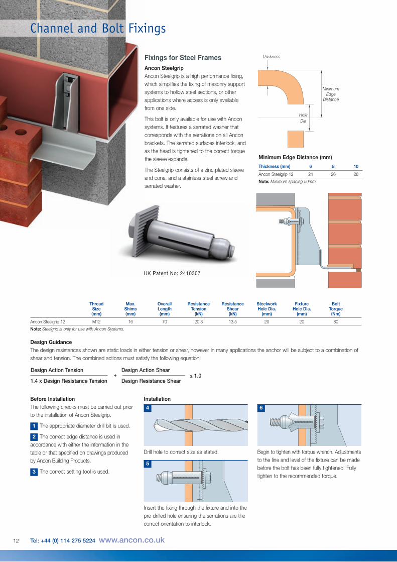
Thread Max. Overall Resistance Resistance Steelwork Fixture BoltSize Shims Length Tension Shear Hole Dia. Hole Dia. Torque(mm) (mm) (mm) (kN) (kN) (mm) (mm) (Nm)
Ancon Steelgrip 12 M12 16 70 20.3 13.5 20 20 80
Note: Steelgrip is only for use with Ancon Systems.
MinimumEdge
Distance
HoleDia
Thickness
Before InstallationThe following checks must be carried out priorto the installation of Ancon Steelgrip.
The appropriate diameter drill bit is used.
The correct edge distance is used inaccordance with either the information in thetable or that specified on drawings producedby Ancon Building Products.
The correct setting tool is used.
Installation
Drill hole to correct size as stated.
4
Begin to tighten with torque wrench. Adjustmentsto the line and level of the fixture can be madebefore the bolt has been fully tightened. Fullytighten to the recommended torque.
6
Insert the fixing through the fixture and into thepre-drilled hole ensuring the serrations are thecorrect orientation to interlock.
5
1
2
3
Fixings for Steel FramesAncon SteelgripAncon Steelgrip is a high performance fixing,which simplifies the fixing of masonry supportsystems to hollow steel sections, or otherapplications where access is only availablefrom one side.
This bolt is only available for use with Anconsystems. It features a serrated washer thatcorresponds with the serrations on all Anconbrackets. The serrated surfaces interlock, andas the head is tightened to the correct torquethe sleeve expands.
The Steelgrip consists of a zinc plated sleeveand cone, and a stainless steel screw andserrated washer.
Thickness (mm) 6 8 10
Ancon Steelgrip 12 24 26 28
Note: Minimum spacing 50mm
Minimum Edge Distance (mm)
UK Patent No: 2410307
Design GuidanceThe design resistances shown are static loads in either tension or shear, however in many applications the anchor will be subject to a combination ofshear and tension. The combined actions must satisfy the following equation:
Design Action Tension Design Action Shear
1.4 x Design Resistance Tension Design Resistance Shear≤ 1.0+
12 Tel: +44 (0) 114 275 5224 www.ancon.co.uk
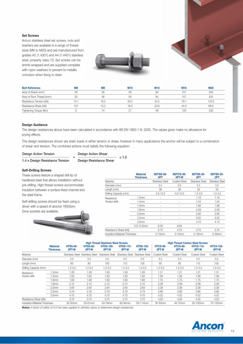
High Thread Stainless Steel Screws High Thread Carbon Steel ScrewsMaterial HTSS-65- HTSS-82- HTSS-100- HTSS-115- HTSS-135- HTCS-65- HTCS-85- HTCS-115- HTCS-135-
Thickness 2PT-W 2PT-W 2PT-W 2PT-W 2PT-W 2PT-W 2PT-W 2PT-W 2PT-W
Material Stainless Steel Stainless Steel Stainless Steel Stainless Steel Stainless Steel Coated Steel Coated Steel Coated Steel Coated Steel
Diameter (mm) 5.5 5.5 5.5 5.5 5.5 5.5 5.5 5.5 5.5
Length (mm) 65 82 100 115 135 65 85 115 135
Drilling Capacity (mm) 1.2-3.2 1.2-3.2 1.2-3.2 1.2-3.2 1.2-3.2 1.2-3.2 1.2-3.2 1.2-3.2 1.2-3.2
Resistance 1.2mm 1.28 1.28 1.28 1.28 1.28 1.21 1.21 1.21 1.21Tension (kN) 1.4mm 1.63 1.63 1.63 1.63 1.63 1.58 1.58 1.58 1.58
1.6mm 1.83 1.83 1.83 1.83 1.83 1.75 1.75 1.75 1.751.8mm 2.12 2.12 2.12 2.12 2.12 2.08 2.08 2.08 2.082.0mm 2.64 2.64 2.64 2.64 2.64 2.39 2.39 2.39 2.392.5mm 3.79 3.79 3.79 3.79 3.79 3.86 3.86 3.86 3.863.0mm 4.75 4.75 4.75 4.75 4.75 4.52 4.52 4.52 4.52
Resistance Shear (kN) 3.75 3.75 3.75 3.75 3.75 4.50 4.50 4.50 4.50Insulation/Material Thickness 35-50mm 35-61mm 43-79mm 60-94mm 65-114mm 35-50mm 45-70mm 55-100mm 75-120mm
Notes: A factor of safety of 2.0 has been applied to ultimate values to determine design resistances
Set ScrewsAncon stainless steel set screws, nuts andwashers are available in a range of threadsizes (M6 to M20) and are manufactured fromgrades A2 (1.4301) and A4 (1.4401) stainlesssteel, property class 70. Set screws can beshrink-wrapped and are supplied completewith nylon washers to prevent bi-metalliccorrosion when fixing to steel.
Self-Drilling ScrewsThese screws feature a shaped drill tip ofhardened steel that allows installation withoutpre-drilling. High thread screws accommodateinsulation between a surface-fixed channel andthe steel frame.
Self-drilling screws should be fixed using adriver with a speed of around 1800rpm.Drive sockets are available.
Bolt Reference M6 M8 M10 M12 M16 M20
Area of Shank (mm2) 28 36 58 84 157 245
Area of Root Thread (mm2) 20 36 58 84 157 245
Resistance Tension (kN) 10.1 18.5 29.2 42.5 79.1 123.5
Resistance Shear (kN) 5.6 10.3 16.2 23.6 44.0 68.6
Tightening Torque (Nm) 6 14 27 48 120 230
Material SDTSS-38- SDTCS-38- SDTSS-35- SDTSS-55-Thickness 5PT 5PT-W 2PT 2PT
Material Stainless Steel Coated Steel Stainless Steel Stainless SteelDiameter (mm) 5.5 5.5 5.5 5.5Length (mm) 38 38 35 55Drilling Capacity (mm) 4.0-12.0 4.0-12.0 1.2-3.2 1.2-3.2
Resistance 1.2mm - - 1.16 1.16Tension (kN) 1.4mm - - 1.54 1.54
1.6mm - - 1.68 1.681.8mm - - 2.09 2.092.0mm - - 2.60 2.602.5mm - - 3.52 3.523.0mm - - 4.10 4.10
4.0-12.0mm 6.45 8.84 - -Resistance Shear (kN) 3.75 4.70 3.75 3.75Insulation/Material Thickness 0-10mm 0-13mm 0-16mm 0-30mm
Design GuidanceThe design resistances above have been calculated in accordance with BS EN 1993-1-8: 2005. The values given make no allowance forprying effects.
The design resistances shown are static loads in either tension or shear, however in many applications the anchor will be subject to a combinationof shear and tension. The combined actions must satisfy the following equation:
Design Action Tension Design Action Shear
1.4 x Design Resistance Tension Design Resistance Shear≤ 1.0+
13
Channel and Bolt Fixings
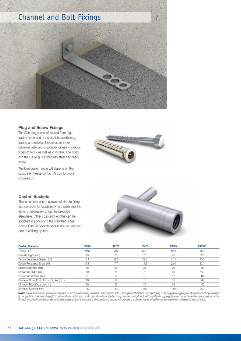
Plug and Screw FixingsThe SX8 plug is manufactured from highquality nylon and is resistant to weathering,ageing and rotting. It requires an 8mmdiameter hole and is suitable for use in varioustypes of block as well as concrete. The fixinginto the SX plug is a stainless steel hex headscrew.
The load performance will depend on thesubstrate. Please contact Ancon for moreinformation.
Cast-in SocketsThese sockets offer a simple solution to fixinginto concrete for locations where adjustment iseither unnecessary or can be providedelsewhere. Other sizes and lengths can besupplied in addition to the standard range.Ancon Cast-in Sockets should not be used aspart of a lifting system.
Cast-in Sockets 10/75 12/75 16/75 20/75 24/100
Thread Size M10 M12 M16 M20 M24
Overall Length (mm) 75 75 75 75 100
Design Resistance Tension (kN) 8.4 12.2 22.8 31.1 40.5
Design Resistance Shear (kN) 5.3 7.7 14.6 23.0 32.1
Outside Diameter (mm) 16 20 22 26 35
Cross Pin Length (mm) 50 75 75 88 100
Cross Pin Diameter (mm) 6 10 10 12 16
Centre of Cross Pin to End of Socket (mm) 10 12 15 16 20
Minimum Edge Distance (mm) 75 75 75 75 100
Minimum Spacing (mm) 150 150 150 150 200
Note: The published design resistances are based on tests using unreinforced concrete with a strength of 30N/mm2, incorporating a dense gravel aggregate. However crushing strengthis no guide to concrete strength in either shear or tension, and concrete with a similar compressive strength but with a different aggregate may not achieve the same performance.Providing suitable reinforcement is incorporated around the sockets, the published values will provide a sufficient factor of safety for concrete with different characteristics.
14 Tel: +44 (0) 114 275 5224 www.ancon.co.uk
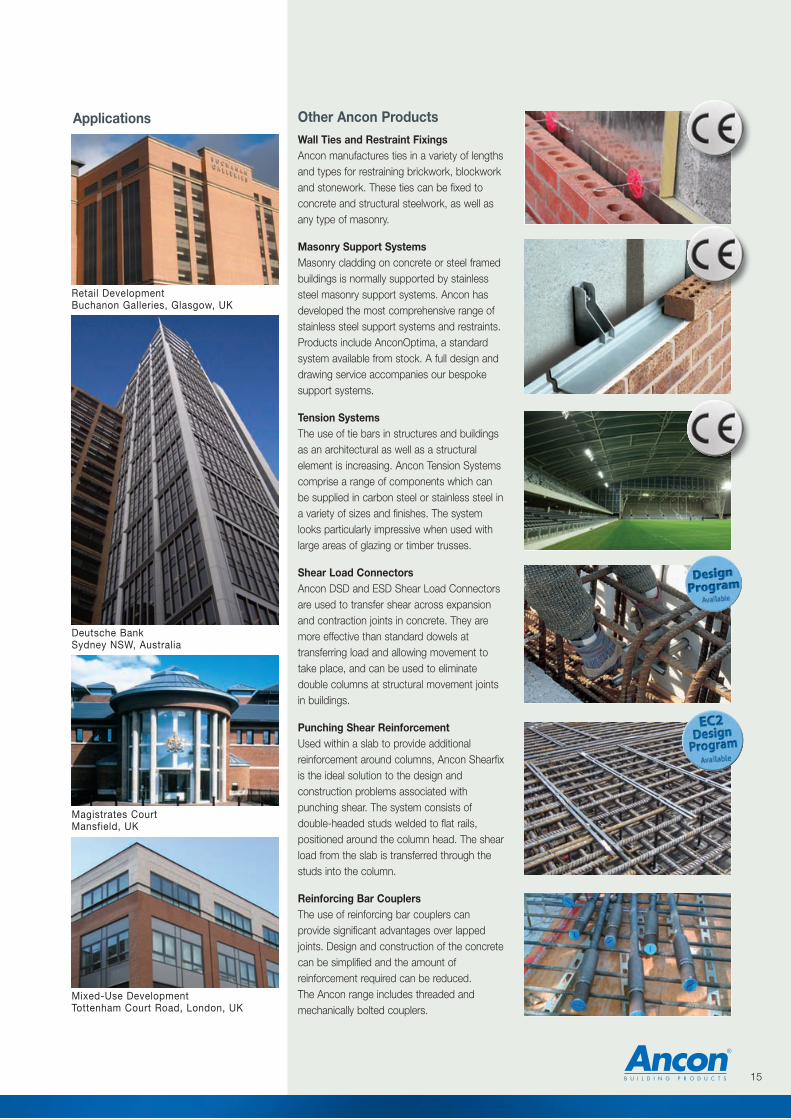
Other Ancon ProductsWall Ties and Restraint FixingsAncon manufactures ties in a variety of lengthsand types for restraining brickwork, blockworkand stonework. These ties can be fixed toconcrete and structural steelwork, as well asany type of masonry.
Masonry Support SystemsMasonry cladding on concrete or steel framedbuildings is normally supported by stainlesssteel masonry support systems. Ancon hasdeveloped the most comprehensive range ofstainless steel support systems and restraints.Products include AnconOptima, a standardsystem available from stock. A full design anddrawing service accompanies our bespokesupport systems.
Tension SystemsThe use of tie bars in structures and buildingsas an architectural as well as a structuralelement is increasing. Ancon Tension Systemscomprise a range of components which canbe supplied in carbon steel or stainless steel ina variety of sizes and finishes. The systemlooks particularly impressive when used withlarge areas of glazing or timber trusses.
Shear Load ConnectorsAncon DSD and ESD Shear Load Connectorsare used to transfer shear across expansionand contraction joints in concrete. They aremore effective than standard dowels attransferring load and allowing movement totake place, and can be used to eliminatedouble columns at structural movement jointsin buildings.
Punching Shear ReinforcementUsed within a slab to provide additionalreinforcement around columns, Ancon Shearfixis the ideal solution to the design andconstruction problems associated withpunching shear. The system consists ofdouble-headed studs welded to flat rails,positioned around the column head. The shearload from the slab is transferred through thestuds into the column.
Reinforcing Bar CouplersThe use of reinforcing bar couplers canprovide significant advantages over lappedjoints. Design and construction of the concretecan be simplified and the amount ofreinforcement required can be reduced.The Ancon range includes threaded andmechanically bolted couplers.
Applications
Retail DevelopmentBuchanon Galleries, Glasgow, UK
Deutsche BankSydney NSW, Australia
Magistrates CourtMansfield, UK
Mixed-Use DevelopmentTottenham Court Road, London, UK
15
ISO 9001: 2008FM 12226
ISO 14001: 2004EMS 505377
OHSAS 18001: 2007OHS 548992
© Ancon Building Products 2013
The construction applications and details provided in this literature are indicative only. In every case, project workingdetails should be entrusted to appropriately qualified and experienced persons.
Whilst every care has been exercised in the preparation of this document to ensure that any advice, recommendations orinformation is accurate, no liability or responsibility of any kind is accepted in respect of Ancon Building Products.
With a policy of continuous product development Ancon Building Products reserves the right to modify product designand specification without due notice.
These products are available from:
Masonry Support Systems
Lintels
Masonry Reinforcement
Windposts and Parapet Posts
Wall Ties and Restraint Fixings
Channel and Bolt Fixings
Tension and Compression Systems
Insulated Balcony Connectors
Shear Load Connectors
Punching Shear Reinforcement
Reinforcing Bar Couplers
Reinforcement Continuity Systems
Stainless Steel Fabrications
Flooring and Formed Sections
Refractory Fixings
Ancon Building Products114 Kurrajong AvenueMount DruittSydneyNSW 2770AustraliaTel: +61 (0) 2 8808 1111Fax: +61 (0) 2 9675 3390Email: [email protected]: www.ancon.com.au
Ancon (Schweiz) AGGewerbezone Widalmi 103216 Ried bei KerzersSwitzerlandTel: +41 (0) 31 750 3030Fax: +41 (0) 31 750 3033 Email: [email protected]: www.ancon.ch
Ancon Building Products GesmbHPuchgasse 1A-1220 ViennaAustriaTel: +43 (0) 1 259 58 62-0Fax: +43 (0) 1 259 58 62-40Email: [email protected]: www.ancon.at
Ancon GmbHBartholomäusstrasse 2690489 NurembergGermanyTel: +49 (0) 911 955 1234 0Fax: +49 (0) 911 955 1234 9Email: [email protected]: www.anconbp.de
Ancon Building ProductsPresident Way, President ParkSheffield S4 7URUnited KingdomTel: +44 (0) 114 275 5224Fax: +44 (0) 114 276 8543Email: [email protected]: www.ancon.co.ukFollow on Twitter: @AnconUK
Ancon (Middle East) FZEPO Box 17225Jebel AliDubaiUnited Arab EmiratesTel: +971 (0) 4 883 4346Fax: +971 (0) 4 883 4347Email: [email protected]: www.ancon.ae
Related Documents