WIRELESS COMMUNICATIONS AND MOBILE COMPUTING Wirel. Commun. Mob. Comput. 2009; 9:557–571 Published online 29 October 2008 in Wiley InterScience (www.interscience.wiley.com) DOI: 10.1002/wcm.701 Channel assignment for multicast in multi-channel multi-radio wireless mesh networks Hoang Lan Nguyen ∗,† and Uyen Trang Nguyen Department of Computer Science and Engineering, York University, Toronto, Canada M3J 1P3 Summary One of the most effective approaches to enhance the throughput capacity of wireless mesh networks (WMN) is to use systems with multiple channels and multiple radios per node. Multi-channel multi-radio (MCMR) networks require efficient channel assignment (CA) algorithms to determine which channel a link should use for data transmission in order to maximize network throughput. The problem of CA has been studied extensively for unicast communications, but addressed only recently for multicast. We propose a CA algorithm named Minimum interference Multi-channel Multi-radio Multicast (M4) that minimizes interference among nodes in a multicast routing tree and uses both orthogonal and overlapping channels such as those in IEEE 802.11b/g systems. Simulation results show that M4 outperforms the Multi Channel Multicast algorithm proposed. in various scenarios with respect to average packet delivery ratio, throughput and end-to-end delay. Copyright © 2008 John Wiley & Sons, Ltd. KEY WORDS: wireless mesh networks; multicast; channel assignment; interference minimization; multi-channel multi-radio systems 1. Introduction Wireless mesh networking is an emerging technology that supports many important applications such as Internet access provisioning in rural areas, ad hoc networking for emergency and disaster recovery, security surveillance, and information services in public transportation systems. The technology enables networking capability where wiring or installing cables is difficult or expensive. In a wireless mesh network (WMN), wireless routers provide multi-hop wireless connectivity from a host to either other hosts in the same network or in the Internet. The wireless routers are often static and form a wireless mesh backbone. Our work in this paper focuses on this mesh backbone, *Correspondence to: Hoang Lan Nguyen, Department of Computer Science and Engineering, York University, Toronto, Canada M3J 1P3. † E-mail: [email protected] and we will use the terms ‘routers’ and ‘nodes’ interchangeably. Wireless mesh networking can be implemented using IEEE 802.11, IEEE 802.15, or more recently, IEEE 802.16 technologies. In this paper, we consider IEEE 802.11 with carrier sense multiple access with collision avoidance (CSMA/CA) medium access control (MAC) because this is currently the most commonly used radio technique for WMNs. Until recently, research on wireless ad hoc networks considers mostly networks with a single channel. The theoretical upper limit of per node throughput capacity in such networks is limited by O(1/ √ n), where n is the number of nodes in the network [1]. The theoretical achievable throughput is even Copyright © 2008 John Wiley & Sons, Ltd.

Welcome message from author
This document is posted to help you gain knowledge. Please leave a comment to let me know what you think about it! Share it to your friends and learn new things together.
Transcript

WIRELESS COMMUNICATIONS AND MOBILE COMPUTINGWirel. Commun. Mob. Comput. 2009; 9:557–571Published online 29 October 2008 in Wiley InterScience(www.interscience.wiley.com) DOI: 10.1002/wcm.701
Channel assignment for multicast in multi-channelmulti-radio wireless mesh networks
Hoang Lan Nguyen∗,† and Uyen Trang NguyenDepartment of Computer Science and Engineering, York University, Toronto, Canada M3J 1P3
Summary
One of the most effective approaches to enhance the throughput capacity of wireless mesh networks (WMN) is to usesystems with multiple channels and multiple radios per node. Multi-channel multi-radio (MCMR) networks requireefficient channel assignment (CA) algorithms to determine which channel a link should use for data transmission inorder to maximize network throughput. The problem of CA has been studied extensively for unicast communications,but addressed only recently for multicast. We propose a CA algorithm named Minimum interference Multi-channelMulti-radio Multicast (M4) that minimizes interference among nodes in a multicast routing tree and uses bothorthogonal and overlapping channels such as those in IEEE 802.11b/g systems. Simulation results show that M4outperforms the Multi Channel Multicast algorithm proposed. in various scenarios with respect to average packetdelivery ratio, throughput and end-to-end delay. Copyright © 2008 John Wiley & Sons, Ltd.
KEY WORDS: wireless mesh networks; multicast; channel assignment; interference minimization; multi-channelmulti-radio systems
1. Introduction
Wireless mesh networking is an emerging technologythat supports many important applications such asInternet access provisioning in rural areas, ad hocnetworking for emergency and disaster recovery,security surveillance, and information services inpublic transportation systems. The technology enablesnetworking capability where wiring or installing cablesis difficult or expensive. In a wireless mesh network(WMN), wireless routers provide multi-hop wirelessconnectivity from a host to either other hosts in thesame network or in the Internet. The wireless routersare often static and form a wireless mesh backbone.Our work in this paper focuses on this mesh backbone,
*Correspondence to: Hoang Lan Nguyen, Department of Computer Science and Engineering, York University, Toronto, CanadaM3J 1P3.†E-mail: [email protected]
and we will use the terms ‘routers’ and ‘nodes’interchangeably.
Wireless mesh networking can be implementedusing IEEE 802.11, IEEE 802.15, or more recently,IEEE 802.16 technologies. In this paper, we considerIEEE 802.11 with carrier sense multiple accesswith collision avoidance (CSMA/CA) medium accesscontrol (MAC) because this is currently the mostcommonly used radio technique for WMNs.
Until recently, research on wireless ad hoc networksconsiders mostly networks with a single channel.The theoretical upper limit of per node throughputcapacity in such networks is limited by O(1/
√n),
where n is the number of nodes in the network[1]. The theoretical achievable throughput is even
Copyright © 2008 John Wiley & Sons, Ltd.

558 H. L. NGUYEN AND U. T. NGUYEN
Fig. 1. Multi-radio multi-channel model.
lower, estimated as θ(1/√
n log n) in a random adhoc network with ideal global scheduling and routing[1]. It has also been shown through experiments thaton a string topology using CSMA/CA MAC such asIEEE 802.11, the throughput degrades approximatelyto 1/n of the raw channel bandwidth [2]. The aboveresults indicate that the throughput capacity of asingle-channel WMN becomes unacceptably low as thenetwork size increases.
Several factors contribute to such a rapid degradationof throughput such as the behavior of the MACprotocols, greediness of the initial nodes, andsubsequent flow starvation of the latter hops. However,the single most important factor is the exposed terminalproblem, worsened by the use of a single-radio single-channel network. One of the most effective approachesto enhance the aggregate network throughput is to usesystems with multiple channels and multiple radios pernode [3–7].
Figure 1 illustrates the multi-channel multi-radio(MCMR) model. The network has n channels, whichmay either overlap, such that a channel partially sharesits spectrum with the adjacent channels, or may becompletely separated (orthogonal). For example, IEEE802.11b/g networks have 11 channels, numbered from1 to 11. Orthogonal channels are separated by at leastfour other channels; for instance, channels 2 and 7 areorthogonal. A host in a MCMR network has m radios(interfaces), and typically 1 < m < n (e.g., m = 3,n = 11). A MCMR node can transmit on one channeland receive on another at the same time using twodifferent radios. As a result, a MCMR wireless networkat least doubles the throughput, since each node is nowin full-duplex mode, being able to transmit and receivesimultaneously. In return, MCMR networks requireefficient algorithms for channel assignment (CA) [4–6,8,9], the task of determining which channel a linkshould use for data transmission in order to minimizeinterference for maximum throughput.
Multicast is a form of communication that deliversinformation from a source to a set of destinationssimultaneously in an efficient manner. Important
applications of multicast include distribution of finan-cial data, billing records, software, and newspapers;audio/video conferencing; distance education; IPtelevision; and distributed interactive games. Althoughmulticast is required to support many importantapplications, research on multicasting in MCMRWMNs is still in its infancy.
The problem of CA has been studied extensivelyin the context of unicast communications [4–6,8,9],and most assumes orthogonal channels [10]. CAfor multicast, however, has only been addressedrecently [11,12]. Zeng et al. [11] proposed a CAalgorithm for multicast in MCMR WMNs calledMulti-Channel Multicast MCM. This algorithm suffersfrom low performance caused by the hidden channelproblem (HCP), and from the inconvenient use ofinterference factors. In this paper, we propose aCA algorithm named Minimum interference Multi-channel Multi-radio Multicast (M4) that eliminatesthe HCP and the use of interference factors. Thealgorithm enables the nodes in a multicast tree tooperate with minimum interference. Like MCM, weconsider both orthogonal and overlapping channelssuch as those in IEEE 802.11b/g systems. Ourexperimental results show that M4 outperforms MCMin various scenarios with respect to average packetdelivery ratio (PDR), throughput and end-to-enddelay.
The remainder of the paper is organized as follows.We briefly describe the MCM algorithm and analyzeits drawbacks in Section 3. We present our proposedCA algorithm and its performance evaluation inSections 4 and 5, respectively. Related work isdiscussed in Section 6, and Section 7 concludes thepaper.
2. Definitions and Assumptions
We consider WMNs with stationary wireless routers.Two nodes are directly connected if they are withinthe radio range of each other and referred to as one-hop neighbors. Two nodes that communicate with eachother via an intermediate node are called two-hopneighbors.
The HCP occurs when two nodes that are two-hopsaway from each other select the same channel and thusinterfere with each other’s transmission. For example,in Figure 2(b), if S and E select the same channel, say,channel 1, and transmit at the same time, their signalswill collide at node C. If C is the intended recipient ofeither transmitter, C will not receive the correct packet.
Copyright © 2008 John Wiley & Sons, Ltd. Wirel. Commun. Mob. Comput. 2009; 9:557–571
DOI: 10.1002/wcm

CHANNEL ASSIGNMENT FOR MULTICAST IN WMNs 559
Fig. 2. An example of channel assignment using MCM.Dotted lines are not part of the multicast tree but shown torepresent direct connectivity between nodes. (a) A multicast
tree. (b) MCM channel assignment.
We assume that nodes that are three or more hopsaway from each other do not interfere. In WMNs(unlike MANETs or many types of sensor networks),we have control over the placement of routers in thenetwork.
Our proposed CA algorithm considers bothoverlapping and orthogonal channels. Our experimentsare based on IEEE 802.11b/g standards [13] in whichthere is a total of 11 channels numbered from 1 to 11.The channel separation between two channels c1 andc2 is defined as |c2 − c1|. For instance, the channelseparation between channel 1 and channel 5 is four.In IEEE 802.11b/g standards, the separation betweenorthogonal channels is at least five (i.e., separated byat least four other channels, e.g., channels 3 and 8).
To measure the level of interference betweenneighboring nodes, the MCM algorithm uses a metricnamed interference factors. The interference factoris defined as the ratio of the interference range overthe transmission range. Zeng et al. [11] described amethod for measuring interference factors. Using fourwireless routers equipped with Netgear WAG511 PCcards to establish two wireless links (one betweeneach pair of routers), the authors moved the twowireless links far away from each other graduallyuntil they did not interfere with each other. Thisgave the interference range of the two links in orderto calculate the interference factor as defined above.Table I lists the interference factors versus channelseparation for 2 Mbits/s, 5.5 Mbits/s, and 11 Mbits/sdata rates obtained from this experiment [11]. Theresults show that the larger the channel separation,the less the interference and the lower the interferencefactor. When the channel separation is five or more, theinterference factors approach zero.
Table I. An example of interference factors in an IEEE 802.11bnetwork [11].
Channel separation 2 Mbits/s 5.5 Mbits/s 11 Mbits/s
0 2.5 2.2 2.01 1.6 1.5 1.22 1.2 1.0 0.73 0.9 0.8 0.54 0.5 0.3 0.2≥ 5 0.0 0.0 0.0
By definition, interference factors depend on thetransmission rate at the physical layer, channelseparation, distances between nodes and environmentalfactors such as signal reflections and multi-path fading.
We assume that a multicast tree has been constructedbefore the CA algorithm is applied, as in MCM. Thegoal of the CA algorithm is to minimize the interferencebetween nodes in the given tree. There exist severalapproaches/algorithms for building multicast trees[14], such as shortest path trees [15–22], minimumSteiner tree [23–27], minimum data overhead tree [28].A performance comparison of these types of trees forsingle-channel WMNs can be found in [29,30].
The parent-child and sibling relationships betweennodes in a multicast tree is the same as those definedfor the traditional rooted tree data structure [31], wherethe root of the tree is the multicast source.
When applying the M4 algorithm, each node in themulticast tree uses only two radios (interfaces): onefor receiving multicast data from its parent (uplinkinterface), and the other for sending multicast datato its children (downlink interface). Other remainingradios, if any, can be used for other flows. Notethat the multicast source has no uplink interface inthe tree, and multicast destinations have no downlinkinterface.
We assume that the network topology as wellas multicast membership are static. In practice,routers may be added to, removed from or movedinside the network; members may join or leave themulticast group freely at will. These events require thereconstruction of the multicast tree and re-computationof the CA. These issues are to be addressed in our futurework.
Finally, multicast data flows are assumed to be one-way, from the source towards the destinations (althoughthe routing protocol and the CA algorithm may requirechildren to sent control messages to their parents.However, this is done before data transmission startsand does not interfere with data packets.)
Copyright © 2008 John Wiley & Sons, Ltd. Wirel. Commun. Mob. Comput. 2009; 9:557–571
DOI: 10.1002/wcm

560 H. L. NGUYEN AND U. T. NGUYEN
3. Multi-Channel Multicast (MCM)
In this section, we briefly describe the MCM algorithmand then analyze its drawbacks.
3.1. The MCM Algorithm
The MCM algorithm considers both overlapping andorthogonal channels. It uses interference factors tominimize interference among one-hop neighboringnodes. The MCM CA algorithm works as follows. Itstarts with the source node by assigning a channel to thedownlink interface of the source. All multicast childrenof the source node then tune into this channel forreceiving multicast data from the source. The algorithmthen processes the source’s children, following abreadth-first search traversal [32] of the multicast tree.For each child, MCM assigns a channel to the downlinkinterface of the node so that the assignment minimizesthe interference factor between this node and all of itsone-hop neighbors who have already been assigned achannel. Specifically, let N(v) denote the set of one-hopneighbors of node v that have already been assigned achannel; cv is the channel that is assigned to node v;δ(cv,cw) is the interference factor between two channelscv and cw. For each forwarding node v in the multicasttree (including the source), MCM selects a channel cv
for v so that it minimizes the following function:∑
∀w∈N(v)
δ2(cv,cw) (1)
If there is more than one channel that satisfies theoptimization function, MCM will randomly chooseone channel from the multiple solutions. The CAprocedure repeats until it covers all forwarding nodesof the routing tree in the order of a breadth-first searchtraversal. An example of the CA produced by the MCMalgorithm is shown in Figure 2. In this example, S is themulticast source; H, J, K, L are multicast destinations;and C, B, E, F are multicast forwarding nodes.
3.2. Drawbacks of MCM
The CA algorithm of MCM suffers from the HCP, andthe use of interference factors is not convenient andnot flexible. Moreover, random selection of a channelfrom multiple choices may not give the best solution.In this section, we discuss these drawbacks of theMCM algorithm.
(1) The hidden channel problem. When computing theoptimization function (1), MCM considers onlythe interference caused by one-hop neighbors of
a node v. For example, in Figure 2(a), if v = E
then the set of neighbors used in function (1) isN(v) = {C}. This, however, causes the HCP, asillustrated in Figure 2(b). In this example, nodeC receives data from node S on channel 1 andis within the transmission range of node E, whotransmits on channel 1 as well. If two signalstransmitted by S and E arrive at C at the sametime, they will collide at node C. The reason isthat node E considers only the channel assignedto node C, its one-hop neighbor, and ignores thetwo-hop neighbor S. A similar scenario happensbetween nodes C, H, and F on channel 11. Ourproposed algorithm improves the MCM algorithmby including a two-hop interference componentin the optimization function, making it aware ofthis HCP.
(2) Interference factors. As discussed earlier, inter-ference factors depend on the transmission ratesat the physical layer, distances between nodesand physical properties of the operating area.Therefore, before applying the MCM algorithm,one needs to acquire the interference factor valuesof a given network and supported data rates. Inaddition, the interference factors obtained in anetwork area may not be applicable to others asthe interference characteristics may not be thesame. Moreover, varying interference factors (dueto varying environmental conditions) are likelyto generate fluctuating CA solutions that are notoptimal. Therefore, the M4 algorithm uses channelnumbers (in combination with its own optimizationfunction) instead of interference factors.
(3) Random selection from multiple choices. AssumingIEEE 802.11b/g, when the channel separation isequal or greater than five channels, the interferencefactor approaches zero [11]. This means thatthere can exist multiple channels that satisfythe objective function. Consider the exampleillustrated by Figure 3(a), in which there are threenodes that are within each other’s transmission
Fig. 3. Channel assignment comparison between MCM andM4. (a) MCM: non-optimal channel assignment. (b) M4:
optimal channel assignment.
Copyright © 2008 John Wiley & Sons, Ltd. Wirel. Commun. Mob. Comput. 2009; 9:557–571
DOI: 10.1002/wcm

CHANNEL ASSIGNMENT FOR MULTICAST IN WMNs 561
range. Since the first node has selected channel1, the possible solutions for the second node arechannels 6, 7, 8, 9, 10 or 11. In this example, thesecond node chooses (randomly) channel 8.
Randomly selecting one of the possible channels,as MCM does, may not give the best performance.Using the above example and optimization function(1), we see that the channel to be chosen for the thirdnode is 11. The solution is thus {1, 8, 11}, resultingin one pair of overlapping channels (8 and 11). On theother hand, the optimal solution is {1, 6, 11}, whichgives us three orthogonal channels and no overlappingchannels (Figure 3(b)). The optimization function inour proposed M4 algorithm supports optimal channelselection when there are multiple choices.
4. The M4 Channel AssignmentAlgorithm
Considering the drawbacks of MCM, we proposea CA algorithm for multicast called M4 that solvesthe HCP and does not use interference factors in theoptimization function.
4.1. Algorithm
We eliminate the HCP by adding to our optimizationfunction the channel information of the two-hopneighbors of a node v. In the example of multicast treein Figure 2, node E is informed of the channel alreadyselected by node S so that it can avoid that channel.Similarly, F should know about the channel informa-tion of node C. How to collect channel information oftwo-hop neighbors is discussed in Section 4.2.
We solve the interference factor problem bydeveloping an optimization function which uses onlychannel numbers (e.g, 1, 2, . . . , 11 in IEEE 802.11b)while maximizing the channel separation among one-hop and two-hop transmitting neighbors.
Let N�(v) denote the set of one-hop and two-hopneighbors of node v that have already been assigneda channel, and cv be the channel used by node v. Wedefine optimization function F (c) as follows:
F (c) =
∏
∀w∈N�(v)
|c − cw|
max∀i∈N�(v)
{|c − ci|} ÷ min∀j∈N�(v)
{|c − cj|} (2)
Then for each multicast forwarding node v in themulticast tree including the source, the M4 algorithmassigns to v a channel cv that maximizes the valueF (cv).
The right hand side of Equation (2) is a fractionwhose numerator is the product of the absolute valuesof the channel separations between v and w, w ∈N�(v). The goal is to maximize the channel separationbetween v and all its neighbors.
To obtain the denominator, M4 finds the maximumand minimum among all channel separations of thecurrently available (cv, cw) neighbor pairs, and thendivides the maximum by the minimum. The objectivehere is to balance the channel separation among allchannel pairs considered. This helps avoid situationssuch as the example in Figure 3(a) where one channelpair is ‘over-separated’ (channels 1 and 8), while theother pair is overlapping (8 and 11). M4 offers theoptimal solution, which is three orthogonal channelpairs from the set {1, 6, 11} (Figure 3(b)).
Thanks to the above optimizations, M4 is able to findCAs with less interference than MCM, which resortsto random selections when there are several channelchoices (compare the CAs in Figure s 3(a) and 3(b) foran example).
To further demonstrate the improvement of M4 overMCM, we use M4 to assign channels to nodes in themulticast tree shown in Figure 2(a). The resulting CAs,after applying Equation (2) to all multicast nodes in themulticast tree, are shown in Figure 4. Compared to the
Fig. 4. Channel assignments in M4. The hidden channel problem in MCM (Figure 2) no longer exists in M4.
Copyright © 2008 John Wiley & Sons, Ltd. Wirel. Commun. Mob. Comput. 2009; 9:557–571
DOI: 10.1002/wcm

562 H. L. NGUYEN AND U. T. NGUYEN
CAs obtained from MCM (Figure 2(b)), the CAs givenby M4 show no hidden channels and no interferenceamong multicast nodes.
4.2. Implementation
We discuss two major issues, namely the collectionof one-hop and two-hop neighbor information and thecomputation of function F (c).
The channel information of two-hop neighborscan be obtained in a distributed manner as follows.After a node v obtains the channel assignment itis assigned, it broadcasts a message containing itsnode ID and the assigned channel number to itsone-hop neighbors. When a neighbor u of node v
receives the broadcast message, u adds its own ID andchannel information to the message (if the channelinformation is available at that time). Node u thenbroadcasts the updated message to its neighbors.Besides channel information, these broadcast messagesalso provide us with the set of one-hop and two-hop neighbors of a node v that have been assignedchannels, N�(v).
In our implementation, we include a hop countvalue with each channel information entry so thatthe information is not propagated beyond two-hopneighbors. Each message is broadcast three times toincrease delivery reliability. To minimize collision,when a node receives a channel information message,it does not re-broadcast a message immediately, butwaits for some random amount of time whose valueis drawn from a distribution. Since we assume staticmembership, the broadcast messages are transmittedbefore data transmission starts, and thus do not interferewith the data traffic. When we consider dynamicjoins/leaves and traffic loads, channels will need to bere-assigned based on the changes. In that case, we willneed more efficient algorithms for nodes to exchangechannel and neighbor information. This, along withsupport for dynamic membership and traffic loads, willbe addressed in our future work (see also 4.3).
With respect to the computation of functionF (c), when Equation (2) gives more than onesolution with the same optimal value Fc, we breakthe tie as follows. The solution with the mostnumber of orthogonal channel pairs is selectedbecause orthogonal channels are more favorable thanoverlapping channels. If the solutions have the samenumber of orthogonal channel pairs, the one withthe node having the least number of one-hop andtwo-hop neighbors is chosen to further minimize theinterference.
4.3. Discussion
When designing the M4 CA algorithm, we recognizedtwo major types of interference among nodes:intra-flow and inter-flow. We discuss how theproposed M4 algorithm handles these types ofinterferences.
(1) Intra-flow interference. For a unicast flow, this isthe interference among nodes on the path from thesource to the destination. For a multicast group, weconsider the whole tree/group as a flow. Multicastintra-flow interference is thus among nodes in therouting tree. When we include all one-hop andtwo-hop neighbors of a multicast node v (i.e., setN�(v)) in Equation (2) of the M4 algorithm, we takeinto account all possible relatives of v within two-hop transmission of v in the routing tree, includingsiblings (i.e., multicast nodes at the same level inthe tree).
(2) Inter-flow interference. This is the interferenceamong nodes belonging to different flows. In thecurrent implementation, we consider only intra-flow interference (i.e., among nodes in a multicasttree). To account for inter-flow interference, wecan incorporate the channel information of otherflows into Equation (2) when performing CA forthe multicast group. We can also apply the M4algorithm to unicast flows by collecting the channelinformation of one-hop and two-hop neighbors ofthe nodes on the source-to-destination path andthen apply Equation (2).
Figure 5 illustrates an example which re-uses themulticast group shown in Figure 4. Assume that theunicast flow with source M and destination N has beenactive on channel 2 when the multicast session starts.When we solve Equation (2) for multicast forwardingnode F, node M of the unicast flow is also included inthe computation; that is, N�(F ) = {C, E, M}, resultingin cF = 9 (recall that cF = 1 in Figure 4 when thereare no other flows).
When inter-flow interference is included in the CAalgorithm, traffic loads must be considered in order toobtain the optimal solution. For instance, when a newflow starts, the CA should be recomputed to accountfor the interference caused by the new flow. Similarly,when a flow terminates, the CA must be updated toexclude the interference of this flow. Furthermore, aflow with very light load incurs less interference thanone with heavy load. In other words, the traffic load of aflow determines its level of interference, and thus must
Copyright © 2008 John Wiley & Sons, Ltd. Wirel. Commun. Mob. Comput. 2009; 9:557–571
DOI: 10.1002/wcm

CHANNEL ASSIGNMENT FOR MULTICAST IN WMNs 563
Fig. 5. Inter-flow interference: co-existence of multicast andunicast flows.
be considered in a CA algorithm, as done in several CAalgorithms (for unicast communications) [4,5,8,33].
The CA could be updated when the traffic loadchanges. However, network load conditions can bevery dynamic; it could be very expensive to keep trackof every change and re-compute the CA accordingly.Therefore, most CA algorithms use the simple methodof periodic updates [4,8,33], i.e., the CA is updatedperiodically, e.g., every one minute [8].
Our future work is to evaluate the proposedalgorithm with dynamic network traffic loads.
5. Experimental Results
We evaluate the performance of M4 and compare it withthat of MCM using QualNet simulator version 4.0 [34].M4 offers two advantages over MCM: (1) eliminatingthe HCP, and (2) avoiding the use of interferencefactors and random channel selections when there existmultiple choices. Therefore, we evaluated two versionsof MCM:
� Original MCM (denoted by MCM).� Improved MCM (denoted by i-MCM). We modified
MCM to eliminate the HCP by considering two-hopneighbors in the CA procedure, but kept the originalform of the MCM optimization function (Section3.1). By comparing M4 with i-MCM, we show thatwe can avoid using interference factors in the CAalgorithm without performance degradation, and thatour channel selection strategy performs better thanthat of MCM.
The multicast ad-hoc on-demand distance vector(MAODV) protocol [22] is used to build multicastrouting trees (although the CA algorithms of M4 andMCM can be applied to any types of tree). MAODV isprovided by QualNet.
Following are our performance metrics, simulationparameters, and results.
5.1. Performance Metrics
We use the following metrics to measure theperformance of the M4 and MCM algorithms:
� Average multicast packet delivery ratio. The PDRof a receiver is the number of data packets actuallydelivered to the receiver versus the number of datapackets supposed to be received. The average PDRof a multicast group is the average of the PDRs of allthe receivers in the group.
� Average end-to-end delay. The end-to-end delay ofevery packet received at every receiver is recorded;the average over all the packets received is thencomputed.
� Average throughput. The throughput is defined asthe total amount of data a receiver actually receivesdivided by the time between receiving the firstpacket and the last packet. The average taken overall the receivers is the average throughput of themulticast group, assuming that each group has onesender.
5.2. Simulation Parameters
We simulated a small network of 50 wireless routersdistributed over a 1000 m × 1000 m area, and amedium-size network of 100 wireless routers, overa 1700 m × 1700 m area. The nodes are distributeduniformly over the sub-areas within a terrain, and thenodes within a sub-area are randomly placed in thatspace. There are no network partitions throughout thesimulation.
The transmission power of the routers is set constantat 20 dBm; the transmission range of the wirelessrouters is 315 m. We use PHY802.11b at the physicallayer with a transmission rate of 11 Mbits/s. A two-ray propagation model [35] is used when the distancebetween two routers is 250 m or more; otherwise, a freespace model is used to avoid the oscillation caused bythe constructive and destructive combination of the tworays over short distances. The above distance thresholdfor switching between the two models is calculated bythe QualNet software.
Copyright © 2008 John Wiley & Sons, Ltd. Wirel. Commun. Mob. Comput. 2009; 9:557–571
DOI: 10.1002/wcm

564 H. L. NGUYEN AND U. T. NGUYEN
Table II. Common simulation parameters.
Parameter Value
Network size 50 nodes over a 1000 m × 1000 m area100 nodes over a 1700 m × 1700 m area
Path loss model Free space for distances below 200 mtwo-ray for distances of 200 m or more
Router transmission power 20 dBmTransmission rate at physical layer 11 Mbits/sPhysical layer protocol PHY802.11bMedium access control MAC802.11 with DCFMAC for multicast flows CSMA/CAPacket size (excluding header size) 512 bytesQueue size at routers 50 KbytesQueuing policy at routers First-in-first-outTraffic model of sources Constant bit rate (CBR)Duration of each experiment 400 s of simulated timeNumber of runs per data point 10
The MAC802.11 protocol with DCF (DistributedCoordination Function) is chosen as the MACprotocol.We implemented only CSMA/CA withoutRTS (right to send), CTS (clear to send) or ACK(acknowledgment) for multicast MAC. There currentlydoes not exist an effective algorithm for implementingRTS/CTS/DATA/ACK exchanges at the branch pointsof a multicast tree for the following two reasons. First,CTS packets sent by the multicast neighbors of atransmitter have a very high probability of collidingat the transmitter. More importantly, it may not bepossible for all the multicast neighbors to agree on acommon time slot for the transmission of a packet,or the delay would be very long to reach such anagreement. Therefore, all multicast implementations in802.11-based wireless networks so far have used onlyCSMA/CA without RTS/CTS/DATA/ACK exchanges.
The data packet size excluding the header size is512 bytes. The size of the queue at every node is50 Kbytes. The packets in a queue are scheduled ona first-in-first-out basis. We did not implement flowor congestion control in order to test the networkperformance under very high loads.
Each multicast group has one sender. The sender of amulticast group transmits at a constant bit rate properlyset for each experiment. The number of receivers (thegroup size) is also specified for each scenario. Weassume that each sender or receiver is connected toa different wireless router since our work focuses onthe mesh backbone. (In practice, there can be manyhosts communicating with a wireless router, e.g., toform a wireless local area network.) The sender and thereceivers of a multicast group were selected randomly,and the same sender and receivers and the same networkconfiguration were used for all CA algorithms in order
to obtain a fair comparison. All receivers joined amulticast group at the beginning and stayed until thewhole group terminated.
In each experiment, the source sent data for 300 sof simulated time, at a constant bit rate specified foreach experiment. After the source finished sending, thesimulation continued to run for 100 s of simulated timeto give the last packets time to be processed and routed,for a total of 400 s. This 400 s duration did not includethe time needed for constructing the routing tree at thebeginning. Each data point in the graphs was obtainedfrom 10 runs using different randomly generated seednumbers, and the collected data were averaged over the10 runs.
The above parameters are summarized in Table II.To confirm the results reported in this paper, we
also created two more configurations for each datapoint by changing the node placement in the networkand multicast senders and receivers, and repeated theexperiments. The results from these configurations areconsistent with those presented in this paper.
5.3. Scenarios
We considered a small network of 50 nodes in a1000 m × 1000 m area and a medium-size networkof 100 nodes in a 1700 m × 1700 m area. For eachnetwork size, we measure the average PDR, throughoutand end-to-end delay as functions of
� the sender’s sending rate at the application layer (i.e.,traffic load). The rate varies from 10 to 100 packets/s.The multicast group sizes are 20 and 35 receivers inthe small and medium networks, respectively. Weimplemented the IEEE 802.11b 11-channel system.
Copyright © 2008 John Wiley & Sons, Ltd. Wirel. Commun. Mob. Comput. 2009; 9:557–571
DOI: 10.1002/wcm
CHANNEL ASSIGNMENT FOR MULTICAST IN WMNs 565
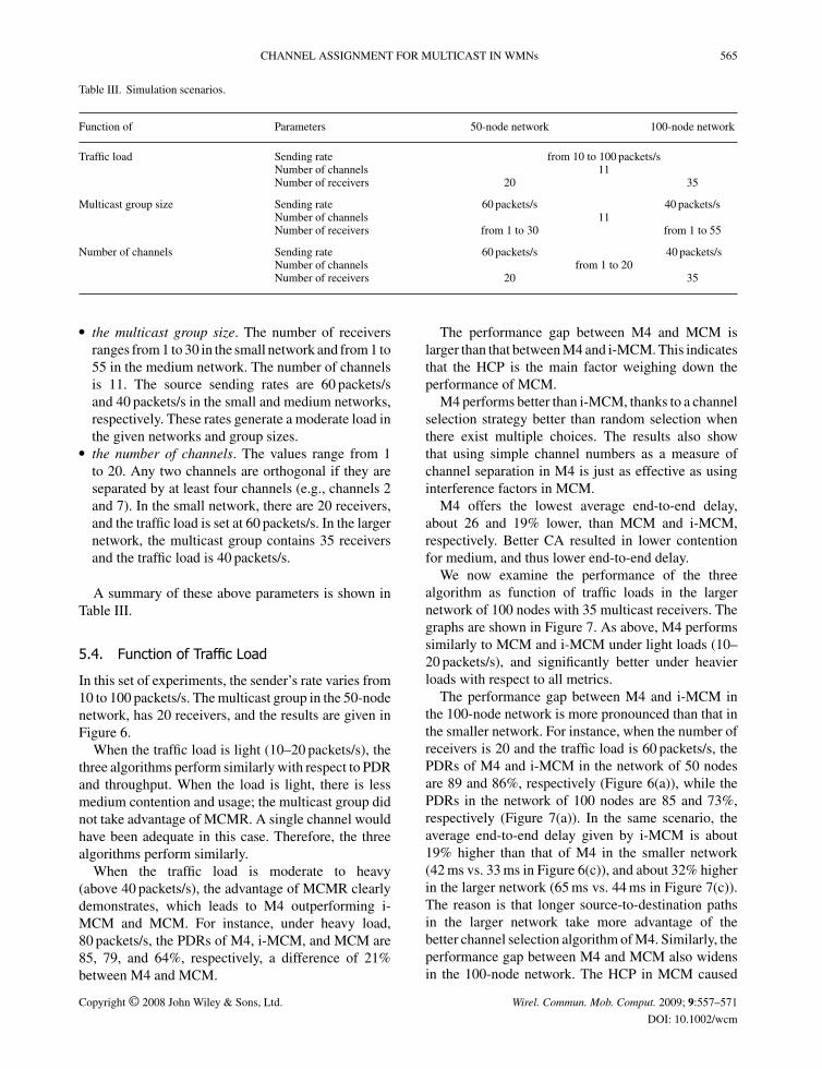
Table III. Simulation scenarios.
Function of Parameters 50-node network 100-node network
Traffic load Sending rate from 10 to 100 packets/sNumber of channels 11Number of receivers 20 35
Multicast group size Sending rate 60 packets/s 40 packets/sNumber of channels 11Number of receivers from 1 to 30 from 1 to 55
Number of channels Sending rate 60 packets/s 40 packets/sNumber of channels from 1 to 20Number of receivers 20 35
� the multicast group size. The number of receiversranges from 1 to 30 in the small network and from 1 to55 in the medium network. The number of channelsis 11. The source sending rates are 60 packets/sand 40 packets/s in the small and medium networks,respectively. These rates generate a moderate load inthe given networks and group sizes.
� the number of channels. The values range from 1to 20. Any two channels are orthogonal if they areseparated by at least four channels (e.g., channels 2and 7). In the small network, there are 20 receivers,and the traffic load is set at 60 packets/s. In the largernetwork, the multicast group contains 35 receiversand the traffic load is 40 packets/s.
A summary of these above parameters is shown inTable III.
5.4. Function of Traffic Load
In this set of experiments, the sender’s rate varies from10 to 100 packets/s. The multicast group in the 50-nodenetwork, has 20 receivers, and the results are given inFigure 6.
When the traffic load is light (10–20 packets/s), thethree algorithms perform similarly with respect to PDRand throughput. When the load is light, there is lessmedium contention and usage; the multicast group didnot take advantage of MCMR. A single channel wouldhave been adequate in this case. Therefore, the threealgorithms perform similarly.
When the traffic load is moderate to heavy(above 40 packets/s), the advantage of MCMR clearlydemonstrates, which leads to M4 outperforming i-MCM and MCM. For instance, under heavy load,80 packets/s, the PDRs of M4, i-MCM, and MCM are85, 79, and 64%, respectively, a difference of 21%between M4 and MCM.
The performance gap between M4 and MCM islarger than that between M4 and i-MCM. This indicatesthat the HCP is the main factor weighing down theperformance of MCM.
M4 performs better than i-MCM, thanks to a channelselection strategy better than random selection whenthere exist multiple choices. The results also showthat using simple channel numbers as a measure ofchannel separation in M4 is just as effective as usinginterference factors in MCM.
M4 offers the lowest average end-to-end delay,about 26 and 19% lower, than MCM and i-MCM,respectively. Better CA resulted in lower contentionfor medium, and thus lower end-to-end delay.
We now examine the performance of the threealgorithm as function of traffic loads in the largernetwork of 100 nodes with 35 multicast receivers. Thegraphs are shown in Figure 7. As above, M4 performssimilarly to MCM and i-MCM under light loads (10–20 packets/s), and significantly better under heavierloads with respect to all metrics.
The performance gap between M4 and i-MCM inthe 100-node network is more pronounced than that inthe smaller network. For instance, when the number ofreceivers is 20 and the traffic load is 60 packets/s, thePDRs of M4 and i-MCM in the network of 50 nodesare 89 and 86%, respectively (Figure 6(a)), while thePDRs in the network of 100 nodes are 85 and 73%,respectively (Figure 7(a)). In the same scenario, theaverage end-to-end delay given by i-MCM is about19% higher than that of M4 in the smaller network(42 ms vs. 33 ms in Figure 6(c)), and about 32% higherin the larger network (65 ms vs. 44 ms in Figure 7(c)).The reason is that longer source-to-destination pathsin the larger network take more advantage of thebetter channel selection algorithm of M4. Similarly, theperformance gap between M4 and MCM also widensin the 100-node network. The HCP in MCM caused
Copyright © 2008 John Wiley & Sons, Ltd. Wirel. Commun. Mob. Comput. 2009; 9:557–571
DOI: 10.1002/wcm

566 H. L. NGUYEN AND U. T. NGUYEN
Fig. 6. Functions of traffic load—50-node network.(a) Average PDR. (b) Average throughput. (c) Average end-
to-end delay.
more collision and congestion when there were morenodes on a source-to-destination path.
For all three algorithms in both networks, as thesender’s rate increases, the throughput increases asexpected; the PDR decreases because higher loadscause more congestion and collisions, resulting morepackets dropped or damaged.
Fig. 7. Functions of traffic load—100-node network.(a) Average PDR. (b) Average throughput. (c) Average end-
to-end delay.
5.5. Function of Number of Channels
The number of channels in this set of experiments isvaried from 1 to 20. The multicast group in the 50-nodenetwork has 20 receivers, and its source sends at a rateof 60 packets/s. This rate yields a moderate load for thegiven group size in this network.
Copyright © 2008 John Wiley & Sons, Ltd. Wirel. Commun. Mob. Comput. 2009; 9:557–571
DOI: 10.1002/wcm

CHANNEL ASSIGNMENT FOR MULTICAST IN WMNs 567
The results in Figure 8 show that M4 and i-MCMoutperform MCM in all cases, thanks to the eliminationof the HCP. When the number of channels is 20,the PDRs of M4 and MCM are 94.1 and 89.6%,respectively. The average end-to-end delay of M4 is25.8% lower than that of MCM. Note that in thenetwork with only one channel the results from the
Fig. 8. Functions of number of channels—50-node network.(a) Average PDR. (b) Average throughput. (c) Average end-
to-end delay.
three algorithms are almost the same as we wouldexpect.
The performance of M4 is only slightly better thanthan of i-MCM in this set of experiments. Note,however, that our intention was to replace interferencefactors with a metric that is simpler, more convenient,and more flexible. To that end, our optimization
Fig. 9. Functions of number of channels—100-node network.(a) Average PDR. (b) Average throughput. (c) Average end-
to-end delay.
Copyright © 2008 John Wiley & Sons, Ltd. Wirel. Commun. Mob. Comput. 2009; 9:557–571
DOI: 10.1002/wcm

568 H. L. NGUYEN AND U. T. NGUYEN
function using simple channel numbers to measure thedegree of channel separation proves to be as effectiveas interference factors, because M4 performs similarlyto or better than i-MCM in all cases.
In the 100-node network, we simulated a multicastgroup having 35 receivers and a source rateof 40 packets/s (Figure 9). Again, M4 performs
Fig. 10. Functions of group size—50-node network. (a)Average PDR. (b) Average throughput. (c) Average end-to-
end delay.
better than MCM and i-MCM. The performancegap between M4 and MCM/i-MCM magnifies asthe network size increases, for the same reasonas explained above (longer source-to-destinationpaths).
For all three algorithms in both networks, as thenumber of channels increases, the PDR and throughput
Fig. 11. Functions of group size—100-node network.(a) Average PDR. (b) Average throughput. (c) Average end-
to-end delay.
Copyright © 2008 John Wiley & Sons, Ltd. Wirel. Commun. Mob. Comput. 2009; 9:557–571
DOI: 10.1002/wcm
CHANNEL ASSIGNMENT FOR MULTICAST IN WMNs 569
increases, and the average end-to-end delay decreases.The higher the number of channels, the less time spentcontending for the medium. However, the performanceof M4 increases at a faster rate than MCM, thanks tothe elimination of the HCP and better optimizationfunction.
5.6. Function of Group Size
In the 50-node network, the multicast group sizeis increased from 1 to 30, while the number ofchannels and sender’s rate are set to 11 and60 packets/s, respectively. The results are shown inFigure 10, which indicate that M4 performs betterthan MCM and i-MCM in almost all cases, especiallywhen the group size is large. For instance, whenthe number of receivers is 30, the PDR of M4 is85%, i.e., 9 and 14% higher than that of i-MCMand MCM, respectively (Figure 10(a)). Similarly, theaverage end-to-end delay of M4 is 12.9% lower thanthat of i-MCM (27 ms vs. 31 ms) and 30.7% lowerthan that of MCM (27 ms vs. 39 ms), as shown inFigure 10(c).
As the group size increases, the more traffic is createdin the network. Therefore, the PDR and throughput ofthe three algorithms go down slightly. Similarly, theaverage end-to-end delays tend to go up as the groupsize increases.
We conducted the same experiment with 100-nodenetwork with the group size varying from 1 to 55. Theresults of this experiment, shown Figure 11, provide asimilar comparison between M4, MCM, and i-MCM.Specifically, when the multicast group size was 45, M4achieved a PDR of 89%, while the PDRs of i-MCMand MCM were lower, at 84 and 79%, respectively(Figure 11(a)). The average end-to-end delay of M4was 50 ms, 10.7 and 24% lower than that of i-MCM(56 ms) and MCM (66 ms), respectively (Figure 11(c)).Again, although i-MCM performs better than MCM,its results were not as good as M4 due to M4’s betteroptimization function.
6. Related Work
Recent work on multicast in WMNs focuses onmulticast routing and performance study of routingapproaches in single-channel networks [28–30,36–39].On the other hand, the problem of CA in multi-radiomulti-channel WMNs has been studied extensively forunicast communications [5,6,8,9,40–42].
In the context of unicast communications, the CAproblem can be classified into three approaches: (1)routing first, CA second [8,9]; (2) CA first, routingsecond [6,40,41]; and (3) joint CA and routing [5,42].For instance, the protocol by Raniwala and Chiueh[8] performs routing first, followed by CA. The CAalgorithm is called load-aware CA, because the trafficloads of the links are known at the time CA isperformed. The protocol carries out the procedureof routing and CA periodically because link trafficloads may change over time. Tang et al. [6] usethe second approach in their algorithm: CA is donefirst, followed by routing. Thanks to the CA result,the interference among links is given, and routingunder this constraint is called interference-awarerouting. Alicherry and Li [5], on the other hand, uselinear programming to solve the problems of CA androuting simultaneously, taking into account the inter-dependence between routing and CA to maximizethe network throughput. Most of existing work onCA for unicast communications assumes orthogonalchannels.
The problem of CA for multicast has only beenstudied recently [11,12]. The MCM algorithm [11]suffers from the HCP as discussed earlier. Theoptimization function in the algorithm by Yin et al.[12] depends on the use of the probability that achannel is being busy. The paper did not mention howto compute this probability; furthermore, collectingand maintaining this information for all links inthe network would incur high overheads. Both theabove algorithms and ours in this paper assumethat a multicast routing tree is first constructed, andCA is then applied (i.e., the first approach listedabove).
7. Conclusion
We propose a CA algorithm for multicast in MCMRWMNs. We discuss the drawbacks of the MCMalgorithm, and propose the solution to the HCP aswell as an optimization function that does not rely onthe computation of interference factors. Advantagesof the proposed CA algorithm include its simpleimplementation and high performance. Our simulationresults show that the M4 algorithm outperforms MCMin terms of average PDR, throughput, and end-to-enddelay under various network conditions. Our futurework will address the problem of dynamic groupmembership and incorporate traffic load informationinto the CA algorithm.
Copyright © 2008 John Wiley & Sons, Ltd. Wirel. Commun. Mob. Comput. 2009; 9:557–571
DOI: 10.1002/wcm

570 H. L. NGUYEN AND U. T. NGUYEN
References
1. Gupta P, Kumar PR. The capacity of wireless networks. IEEETransactions on Information Theory 2000; 46: 388–404.
2. Li J, Blake C, Couto DSJD, Lee HI, Morris R. Capacityof ad hoc wireless networks. In Proceedings of ACMInternational Conference on Mobile Computing and Networking(MobiCom’01), 2001; pp. 61–69.
3. Draves R, Padhye J, Zill B. Routing in multi-radio, multi-hopwireless mesh networks. In Proceedings of ACM MobiCom’04,2004; pp. 114–128.
4. Raniwala A, Gopalan K, Chiueh T. Centralized channelassignment and routing algorithms for multi-channel wirelessmesh networks. In Proceedings of ACM SIGMOBILE’04, 2004;pp. 50–65.
5. Alicherry M, Bhatia R, Li L. Joint channel assignment androuting for throughput optimization in multi-radio wirelessmesh networks. In Proceedings of ACM SIGMOBILE’05, 2005;pp. 58–72.
6. Tang J, Xue G, Zhang W. Interference-aware topologycontrol and QoS routing in multi-channel wireless meshnetworks. In Proceedings of ACM SIGMOBILE’05, 2005;pp. 68–77.
7. Kyasanur P, Vaidya NH. Routing and link-layer protocols formulti-channel multi-interface ad hoc wireless networks. InProceedings of ACM SIGMOBILE’06, 2006; pp. 31–43.
8. Raniwala A, Chiueh T. Architecture and algorithmsfor an IEEE 802.11-based multi-channel wireless meshnetworks. In Proceedings of IEEE InfoCom’05, 2005;pp. 2223–2234.
9. Das AK, Alazemi HMK, Vijayakumar R, Roy S. Optimizationmodels for fixed channel assignment in wireless mesh networkswith multiple radios. In Proceedings of IEEE SECON’05, 2005;pp. 463–474.
10. Fuxjager P, Valerio D, Ricciato F. The myth of non-overlappingchannels: interference measurements in IEEE 802.11. InProceedings of IEEE Wireless on Demand Network Systems andServices (WONS’07), 2007; pp. 1–8.
11. Zeng GW, Ding B, Xiao YL, Mutka M. Multicast algorithms formulti-channel wireless mesh networks. In Proceedings of IEEEInternational Conference on Network Protocols (ICNP’07),2007; pp. 1–10.
12. Yin Z, Li Z, Chen M. A novel channel assignment algorithm formulticast in multi-radio wireless mesh networks. In Proceedingsof IEEE ISCC’07, 2007; pp. 283–288.
13. O’Hara B, Petrick A. 802.11 Handbook: A Designer’sCompanion. IEEE Press: New York, USA, 2005.
14. Nguyen UT, Nguyen HL. Multicast routing algorithms.Technical Report CSE-2008-08, Department of ComputerScience and Engineering, York University, 2008.
15. Dijkstra EW. A note on two problems in connexion with graphs.Numerical Mathematics 1959; 1: 269–271.
16. Bellman R. Dynamic Programming. Princeton University Press:New Jersey, USA, 1957.
17. Cheng C, Riley R, Kumar S, Garcia-Luna-Aceves J. A Loop-freeextended bellman-ford routing protocol without bouncing effect.ACM SIGCOMM Computer Communications Review, Vol. 19,September 1989; pp. 224–236.
18. Sloman MS, Andriopoulos X. Routing algorithm for inter-connected local area networks. Computer Networks and ISDNSystems 1985; 9: 109–130.
19. Waitzman D, Partridge C, Deering S. Distance Vector MulticastRouting Protocol. RFC 1075, November 1988.
20. Moy J. Multicast Extensions to OSPF. RFC 1584, March 1994.21. Lee SJ, Gerla M, Chiang CC. On-demand multicast routing
protocol. In Proceedings of IEEE WCNC’99, 1999; pp. 1298–1302.
22. Royer EM, Perkins CE. Multicast operation of the ad-hoc on-demand distance vector routing protocol. In Proceedings ofACM/IEEE MobiCom’99, 1999; pp. 207–218.
23. Kou L, Markowsky G, Berman L. A fast algorithm for steinertrees. Acta Informatica 1981; 2: 141–145.
24. Takahashi H, Matsuyama A. An approximate solution for theSteiner problem in graphs. Mathematica Japonica 1980; 24:573–577.
25. Zelikovsky A. An 11/6-approximation algorithm for the networkSteiner problem. Algorithmica 1993; 9: 463–470.
26. Winter P. Steiner problem in networks: a survey. Networks 1987;17: 129–167.
27. Winter P, Smith JM. Path-distance heuristics for the Steinerproblem in undirected networks. Algorithmica 1992; 7: 309–327.
28. Ruiz PM, Gomez-Skarmeta AF. Approximating optimalmulticast trees in wireless multihop networks. In Proceedingsof IEEE ISCC’05, 2005; pp. 686–691.
29. Nguyen U, Xu J. Multicast routing in wireless meshnetworks: minimum cost trees or shortest path trees? IEEECommunications Magazine 2007; 45: 72–77.
30. Nguyen HL, Nguyen UT. Minimum interference channelassignment for multicast in multi-radio wireless meshnetworks. In Proceedings of IEEE International Wire-less Communications and Mobile Computing Conference(IWCMC’08).
31. Weiss MA. Data Structures and Algorithm Analysis in Java.Addison-Wesley: Boston, USA, 2007.
32. Cormen TH, Leiserson CE, Rivest RL, Stein C. Introduction toAlgorithms. The MIT Press: Cambridge, MA, USA, 2001.
33. Lin C-J, Chou C-F. Route-aware load-balanced resourceallocation for wireless mesh networks. In Proceedings ofIEEE Wireless Communications and Networking Conference(WCNC’07), 2007; pp. 3093–3511.
34. Qualnet Simulator. Available online at: http://www.qualnet.com35. Schafer W, Lutz E. Propagation characteristics of short-range
radio links at 60 GHz for mobile intervehicle communication. InProceedings of IEEE Telecommunications Symposium (ITS’90),1990; pp. 212–216.
36. Roy S, Koutsonokolas D, Das S, Hu YC. High-throughputmulticast routing metrics in wireless mesh networks. InProceedings of IEEE ICDCS’06, 2006; pp. 48–48.
37. Zhao X, Chou CT, Guo J, Jha S. Protecting multicastsessions in wireless mesh networks. In Proceedings of IEEEConference on Local Computer Networks (LCN’06), 2006;pp. 467–474.
38. Yuan J, Li Z, Yu W, Li B. A cross-layer optimizationframework for multihop multicast in wireless mesh networks.IEEE Journal on Selected Areas in Communications 2006; 24:2092–2103.
39. Zhao X, Chou CT, Guo J, Jha S. Protecting multicast sessions inwireless mesh networks. In Proceedings of IEEE LCN’06, 2006;pp. 467–474.
40. Marina M, Das S. A topology control approach forutilizing multiple channels in multi-radio wireless meshnetworks. In Proceedings of IEEE International Con-ference on Broadband Networks (Broadnets’05), 2005;pp. 381–390.
41. Subramanian AP, Gupta H, Das SR. Minimum interferencechannel assignment in multi-radio wireless mesh networks. InAnnual IEEE Communications Society Conference on Sensor,Mesh and Ad Hoc Communications and Networks (SECON’07),2007; pp. 481–490.
42. Kodialam M, Nandagopal T. Characterizing the capacityregion in multi-radio multi-channel wireless mesh net-works. In Proceedings of ACM International Conference onMobile Computing and Networking (MobiCom’05), 2005;pp. 73–87.
Copyright © 2008 John Wiley & Sons, Ltd. Wirel. Commun. Mob. Comput. 2009; 9:557–571
DOI: 10.1002/wcm

CHANNEL ASSIGNMENT FOR MULTICAST IN WMNs 571
Authors’ Biographies
Hoang Lan Nguyen is currently a Ph.D.student at the Department of ComputerScience and Engineering, York Uni-versity (Toronto, Canada). He receivedhis B.E degree with the highest honorsin Telecommunications in 2003 fromthe University of Wollongong (NSW,Australia), and his M.Sc. degree inComputer Science from York University
in 2006. Before joining York University, he worked forAustralia Nortel Networks as a software engineer. Hiscurrent research interests include wireless communications,multicast routing, and network security.
Uyen Trang Nguyen received herBachelor of Computer Science andMaster of Computer Science degrees in1993 and 1997 from Concordia Univer-sity, Montreal, Canada. She completedher Ph.D. degree at the Universityof Toronto, Canada, in 2003. From1995 to 1997 she was a softwareengineer at Nortel Networks, Montreal,
Canada. She joined the Department of Computer Scienceand Engineering at York University, Toronto, Canada,in 2002 and is currently an Associate Professor. Herresearch interests are in the areas of wireless ad-hocnetworks, multipoint communications, and multimediaapplications.
Copyright © 2008 John Wiley & Sons, Ltd. Wirel. Commun. Mob. Comput. 2009; 9:557–571
DOI: 10.1002/wcm
Related Documents