Form 34731 (RS8) Duke Power Company (1)ID No. AP/3/A/1700/07 PROCEDURE PROCESS RECORD Change(s) . to 0 Incorporated PREPARATION (2) Station OCONEE NUCLEAR STATION (3) Procedure Title LOSS OF LOW PRESSURE INJECTION SYSTEM (4) Prepared By Date g / 9 (5) Reviewed By -4- )$.2 Date J Cross-Disciplinary Review y N/R (6) Temporary Approval (if necessary) By (SRO) Date By Date (7) Approved By 7~~Date ~ (8) Miscellaneous Reviewed/Approved By Date .. Reviewed/Approved By Date (9) Comments (For procedure reissue indicate whether additional changes, other than previously approved changes, are in cluded. Attach additional pages, if necessary.) Additional Changes Included. M Yes (10) Compared with Control Copy Date (11) Requires change to FSAR not identified in 1 OCFR50.59 evaluation? O Yes If "yes", attach detailed explanation. 3 No Completion (12) Date(s) Performed (13) Procedure Completion Verification O Yes O N/A Check lists and/or blanks property initialed, signed, dated or filled in N/A or N/R, as appropriate? O Yes O N/A Usted enclosures attached? O Yes O N/A Data sheets attached, completed, dated and signed? O Yes O N/A Charts, graphs, etc. attached and properly dated, identified and marked? O Yes O N/A Procedure requirements met? Verified By Date (14) Procedure Completion Approved Date (15) Remarks (attach additional pages, if necessary) 910725008B 910715 PDR ADOCK 05000287 P PDR

Welcome message from author
This document is posted to help you gain knowledge. Please leave a comment to let me know what you think about it! Share it to your friends and learn new things together.
Transcript

Form 34731 (RS8)
Duke Power Company (1)ID No. AP/3/A/1700/07
PROCEDURE PROCESS RECORD Change(s) . to
0 Incorporated
PREPARATION (2) Station OCONEE NUCLEAR STATION
(3) Procedure Title LOSS OF LOW PRESSURE INJECTION SYSTEM
(4) Prepared By Date g / 9 (5) Reviewed By -4- )$.2 Date J
Cross-Disciplinary Review y N/R
(6) Temporary Approval (if necessary)
By (SRO) Date
By Date
(7) Approved By 7~~Date ~
(8) Miscellaneous
Reviewed/Approved By Date ..
Reviewed/Approved By Date
(9) Comments (For procedure reissue indicate whether additional changes, other than previously approved changes, are included. Attach additional pages, if necessary.) Additional Changes Included. M Yes
(10) Compared with Control Copy Date
(11) Requires change to FSAR not identified in 1 OCFR50.59 evaluation? O Yes If "yes", attach detailed explanation. 3 No
Completion (12) Date(s) Performed
(13) Procedure Completion Verification
O Yes O N/A Check lists and/or blanks property initialed, signed, dated or filled in N/A or N/R, as appropriate?
O Yes O N/A Usted enclosures attached?
O Yes O N/A Data sheets attached, completed, dated and signed?
O Yes O N/A Charts, graphs, etc. attached and properly dated, identified and marked?
O Yes O N/A Procedure requirements met?
Verified By Date
(14) Procedure Completion Approved Date
(15) Remarks (attach additional pages, if necessary)
910725008B 910715 PDR ADOCK 05000287 P PDR

Unit 3 Page i
LOSS OF LOW PRESSURE INJECTION SYSTEM AP/3/A/1700/07
TABLE OF CONTENTS
Page
CASE A: Failure Of One Train Of The LPI System During ECCS Operation
1.0 Purpose 1
2.0 Symptoms 1
3.0 Automatic Systems Actions 1
4.0 Immediate Manual Actions 2
5.0 Subsequent Actions 3
CASE B: Loss Of Low Pressure Injection System During Decay Heat Removal
1.0 Purpose 9
2.0 Symptoms 9
3.0 Automatic Systems Actions 9
4.0 Immediate Manual Actions 10
5.0 Subsequent Actions 11
6.0 Enclosures
6.1 Establishing RB Containment Closure 25
6.2 East Penetration Room Valve Checklist 33
6.3 West Penetration Room Valve Checklist 37
6.4 Miscellaneous Valve Checklist 40
6.5 Elapsed Time Until Core Boiling, Core
Uncovery, and Core Damage Following Loss
of DHR Capability 41

OCONEE NUCLEAR STATION
LOSS OF LOW PRESSURE INJECTION SYSTEM AP/3/A/1700/07
CASE A
Failure Of One Train Of The LPI System During ECCS Operation
1.0 Purpose
This case of this procedure provides the actions necessary following failure of one train of the LPI System during ECCS operation to restore flow to both LPI Hdrs, if possible.
2.0 Symptoms
* "LP INJECTION LOOP A FLOW HIGH/LOW" statalarm
(3SA-3, C-8)
* "LP INJECTION LOOP B FLOW HIGH/LOW" statalarm
(3SA-3, C-9)
* Failure of 3LP-17 ('3A' LP Injection) or
3LP-18*('3B' LP Injection) to "OPEN."
3.0 Automatic Systems Actions
None

Unit 3 Page 2 of 47
LOSS OF LOW PRESSURE INJECTION SYSTEM AP/3/A/1700/07
CASE A
Failure Of One Train Of The LPI System During ECCS Operation
Immediate Manual Actions
4.0 Immediate Manual Actions
NOTE Manual actions are required within 15 minutes of failure.
4.1 IF an LP Injection valve failed
to automatically open:
* 3LP-17 ('3A' LP Injection)
* 3LP-18 ('3B' LP Injection),
AND CANNOT be remotely operated,
* THEN send an Operator to open the valve(s)
manually.
4.2 IF an LPI pump failed to automatically start:
* '3A' LPI pump
* '3B' LPI pump,
THEN start the LPI pump.

Unit 3 Page 3 of 47
LOSS OF LOW PRESSURE INJECTION SYSTEM AP/3/A/1700/07
CASE A
Failure Of One Train Of The LPI System During ECCS Operation
Subsequent Actions
5.0 Subsequent Actions
5.1 Verify that the LPI System is lined up for ES conditions:
* REFER TO OP/3/A/1104/04, LOW PRESSURE INJECTION
SYSTEM.
5.2 IF an LPI pump fails to start
AND '3C' LPI pump is available,
THEN open the following valves:
* 3LP-6 ('3C' LPI Pump Suction ('A' Hdr))
* 3LP-7 ('3C' LPI Pump Suction ('B' Hdr))
5.2.1 IF the '3A' LPI pump is off,
THEN align the '3C' LPI Pump to 'A' header:
5.2.1.1 Open 3LP-9 ('3C' LPIP Disch to '3A' LPI
Hdr).
5.2.1.2 Start '3C' LPI Pump.
5.2.1.3 Throttle 3LP-12 ('3A' LPI Cooler Outlet
to establish = 3000 gpm flow in 'A'header.

Unit 3 Page 4 of 47
LOSS OF LOW PRESSURE INJECTION SYSTEM AP/3/A/1700/07
CASE A
Failure Of One Train Of The LPI System During ECCS Operation
Subsequent Actions
5.2.2 IF the '3B' LPI pump is off,
THEN align '3C' LPI Pump to 'B' header:
5.2.2.1 Open 3LP-10 Pump ('3C' LPIP Disch
To '3B' LPI Header).
5.2.2.2 Start '3C' LPI Pump.
5.2.2.3 Throttle 3LP-14 ('3B' LPI Cooler
Outlet)to establish = 3000 gpm flow in 'B' header.
5.3 IF only one LPI pump is operating,
THEN open the following valves:
* 3LP-9 ('3C' LPIP Disch to 'A' Hdr)
* 3LP-10 ('3C' LPIP Disch to 'B' Hdr).
5.3.1 Throttle the following valves to establish
1500 gpm in each Hdr:
* 3LP-12 ('3A' LPI Cooler Outlet)
* 3LP-14 ('3B' LPI Cooler Outlet).

Unit 3 Page 5 of 47
LOSS OF LOW PRESSURE INJECTION SYSTEM AP/3/A/1700/07
CASE A
Failure Of One Train Of The LPI System During ECCS Operation
Subsequent Actions
5.4 IF any LPI component required for normal ECCS
operation is inoperable,
* '3A' LPI pump
* '3B' LPI pump
* LPI ES valves
THEN attempt to repair the LPI system,
and
return LPI system to normal ECCS operation.
CAUTION 5.5: If only one LPI cooler is operable, the appropriate LPI and LPSW flows must be established through the operable cooler. This action ensures an adequate core cooldown rate and maintains RB environmental qualification criteria. This requirement is applicable immediately after swapping LPI pump suction from the BWST to the RB EMER Sump.
5.5 IF only one LPI cooler is operable
AND LPI Pump Suction is aligned to the RB
EMER Sump,
THEN open the following valves:
* 3LP-9 ('3C' LPIP Disch to 'A' Hdr)
* 3LP-10 ('3C' LPIP Disch to 'B' Hdr).
5.5.1 IF an LPI line break exists,
THEN send an operator to close the following
valve on the affected Hdr:
*3LP-11 ('3A' LPI Cooler Inlet)
* 3LP-13 ('3B' LPI Cooler Inlet).

Unit 3 Page 6 of 47
LOSS OF LOW PRESSURE INJECTION SYSTEM AP/3/A/1700/07
CASE A
Failure Of One Train Of The LPI System During ECCS Operation
Subsequent Actions
5.5.2 Verify two LPI pumps running.
5.5.3 IF '3A' cooler is operable,
THEN isolate the '3B' cooler:
* Close 3LP-13 ('3B' LPI Cooler
Inlet)
* Close 3LP-14 ('3B' LPI Cooler
Outlet),
AND throttle 3LP-12 ('3A' LPI Cooler
Outlet) to establish = 5000 to 5800
gpm.
5.5.3.1 Increase LPSW flow to the '3A' LPI Cooler to
=.5500 gpm:
* Throttle 3LPSW-405 ('3A' LPI Cooler Outlet Vlv).
5.5.4 IF '3B' cooler is operable,
THEN isolate the '3A' cooler:
* Close 3LP-11 ('3A' LPI .Cooler
Inlet)
* Close 3LP-12 ('3A' LPI Cooler
Outlet),
AND throttle 3LP-14 ('3B' LPI Cooler Outlet
to establish = 5000 to 5800 gpm.

Unit 3 Page 7 of 47
LOSS OF LOW PRESSURE INJECTION SYSTEM AP/3/A/1700/07
CASE A
Failure Of One Train Of The LPI System During ECCS Operation
Subsequent Actions
5.5.4.1 Increase LPSW flow to the '3B' LPI Cooler to
= 5500 gpm:
* Throttle 3LPSW-404 ('3B' LPI
Cooler Outlet Vlv).
5.6 IF one RB EMER Sump suction line is NOT operable:
* 3LP-19 ('3A' Rx Bldg Suction)
* 3LP-20 ('3B' Rx Bldg Suction),
AND LPI suction must be swapped to the RB EMER Sump
from the BWST,
THEN perform the following alignments:
5.6.1 Secure the following to provide adequate
NPSH for the LPI pumps:
* '3A' RBS Pump
* '3B' RBS Pump.
5.6.2 Open the following valves:
* 3LP-6 ('3C' LPI Pump Suction
('A' Hdr))
* 3LP-7 ('3C' LPI Pump Suction
('B' Hdr))
5.6.3 Open the operable valves:
* 3LP-19 ('3A' Rx Bldg Suction)
* 3LP-20 ('3B' Rx Bldg Suction).

Unit 3 Page 8 of 47
LOSS OF LOW PRESSURE INJECTION SYSTEM AP/3/A/1700/07
CASE A
Failure Of one Train Of The LPI System During ECCS Operation
Subsequent Actions
5.6.4 Close the following valves:
* 3LP-21 ('3A' LPI BWST Suction)
* 3LP-22 ('3B' LPI BWST Suction).
5.6.5 Verify RBCUs operation:
* All RBCUs in "LOW" speed
* LPSW flow 1400 gpm to each RBCU.
END

Unit 3 Page 9 of 47
LOSS OF LOW PRESSURE INJECTION SYSTEM AP/3/A/1700/07
'CASE a
Loss Of Low Pressure Injection System During Decay Heat Removal
1.0 Purpose
This case of this procedure provides the actions necessary to reestablish core cooling following a loss of the LPI system during decay heat removal.
2.0 Symptoms
* "LP DECAY HEAT LOOP A FLOW LOW" statalarm
(3SA-3, A-8)
"LP DECAY HEAT LOOP B FLOW LOW" statalarm
(3SA-3, A-9) * RCS incore temperature increasing
* LP cooler outlet temperature increasing
* LPI pump(s) tripped
* "LP INJECTION PUMP A DIFF PRESS LOW" statalarm
(3SA-1, C-12)
0 '"LP INJECTION PUMP B DIFF PRESS LOW" statalarm
(3SA-1, D-12)
* 1"LP INJECTION PUMP C DIFF PRESS LOW" statalarm
(3SA-1, E-12)
* "ULTRASONIC RV LEVEL LOW" Statalarm
(3SA-14, A-5)
3.0 Automatic Systems Actions
None

III
Unit 3 Page 10 of 47
LOSS OF LOW PRESSURE INJECTION SYSTEM AP/3/A/1700/07
CASE B
Loss Of Low Pressure Injection System During Decay Heat Removal
Immediate Manual Actions
4.0 Immediate Manual Actions
4.1 IF LPI pump flow has degraded:
* LPI pump d/P < 130 psid
(3SA-1, C-12/D-12/E-12)
* "LPI Header Flow" < 1000 gpm/hdr
* "LPI pump amps" are fluctuating,
THEN trip the running LPI pump.

Unit 3 Page 11 of 47
LOSS OF LOW PRESSURE INJECTION SYSTEM AP/3/A/1700/07
CASE B
Loss Of Low Pressure Injection System During Decay Heat Removal
Subsequent Actions
5.0 Subsequent Actions
5.1 Verify the LPI Decay Heat Removal valve lineup:
* REFER TO OP/3/A/1104/04, LOW PRESSURE
INJECTION SYSTEM.
NOTE 5.2 The accuracy of LT-5 "Reactor Level" is affected by RB and RCS pressure.
5.2 IF a loss of RCS inventory during LPI decay heat
removal has occurred,
THEN isolate possible leakage paths:
* Secure any draining of the RCS
* Secure LPI purification
and
initiate make up to the RCS:
* Ensure > 1% SDM.
5.2.1 IF the RCS is filled,
THEN maintain PZR level.

Unit 3 Page 12 of 47
LOSS OF LOW PRESSURE INJECTION SYSTEM AP/3/A/1700/07
CASE B
Loss Of Low Pressure Injection System During Decay Heat Removal
Subsequent Actions
5.2.2 IF the RCS is drained
OR the RCS is open,
THEN make up to the RCS via the LPI System
from the BHUTs:
* REFER TO OP/3/A/1103/11,
DRAINING AND NITROGEN
PURGING OF RC SYSTEM.
5.2.3 IF makeup from the BHUTs CANNOT be
established,
THEN makeup to the RCS from the BWST:
5.2.3.1 Open one of the following valves:
* 3LP-21 ('3A' LPI BWST Suction)
* 3LP-22 ('3B' LPI BWST Suction).
5.2.3.2 WHEN RCS level > 10" as indicated by:
* LT-5 Gauge or Comp. Pt. A2103
* Hot Leg Level Comp. Pt. A2101
* Cold Leg Level Comp. Pt. A2102
THEN close the following valves:
* 3LP-21 ('3A' LPI BWST
Suction)
* 3LP-22 ('3B' LPI BWST
Suction).

Unit 3 Page 13 of 47
LOSS OF LOW PRESSURE INJECTION SYSTEM AP/3/A/1700/07
CASE B
Loss Of Low Pressure Injection System During Decay Heat Removal
Subsequent Actions
NOTE 5.3 An LPI pump can experience cavitation if extended operation with < 800 gpm is allowed or adequate NPSH is not maintained.
5.3 IF the LPI pump did NOT experience
"cavitation,"
THEN start the STBY LPI pump.
5.4 IF all of the following conditions are true:
* Core cooling does NOT exist
* RCS is open
* Containment Integrity does NOT exist
THEN establish RB Containment Closure:
* REFER TO Enclosure 6.1 (Establishing
RB Containment Closure).
5.5 IF NO LPI pump is available,
THEN GO TO Step 5.9.

Unit 3 Page 14 of 47
LOSS OF LOW PRESSURE INJECTION SYSTEM AP/3/A/1700/07
CASE B
Loss Of Low Pressure Injection System During Decay Heat Removal
Subsequent Actions
CAUTION 5.6 The RCS can overflow to the RB if the RCS is opened and an LPI flowpath is aligned from the BWST to the RCS.
5.6 IF the LPI pump has experienced "cavitation,"
THEN vent the LPI pumps:
5.6.1 Open one of the following valves:
3LP-21 ('3A' LPI BWST Suction)
* 3LP-22 ('3B' LPI BWST Suction).
5.6.2 Send an Operator to open the following valves:
* 3LWD-369 (LPI Pump '3A' Vent)
* 3LWD-373 (LPI Pump '3B' Vent)
* 3LWD-371 (LPI Pump '3C' Vent).
5.6.3 WHEN a solid stream of water is
visible in the sight glasses,
THEN close the following valves:
* 3LWD-369 (LPI Pump '3A' Vent)
* 3LWD-373 (LPI Pump '3B' Vent)
* 3LWD-371 (LPI Pump '3C' Vent).
5.6.4 Start an LPI pump:
* IF NO LPI pumps are available,
* THEN GO TO Step 5.9.

Unit 3 Page 15 of 47
LOSS OF LOW PRESSURE INJECTION SYSTEM AP/3/A/1700/07
CASE B
Loss Of Low Pressure Injection System During Decay Heat Removal
Subsequent Actions
5.6.5 Close the following valves:
* 3LP-21 ('3A' LPI BWST Suction)
* 3LP-22 ('3B' LPI BWST Suction).
5.6.6 Verify proper LPI pump parameters:
* LPI pump d/P > 130 psid
(3SA-1, C-12/D-12/E-12)
* "LPI Header Flow" > 1000 gpm/hdr
* "LPI Pump Amps" are stable.
5.7 IF the LPI pump(s) "cavitates" after venting,
THEN align LPI pump suction from the BWST and maintain
a stable core temperature:
* < 200aF if CETCs are available
* maintain RxV level on-scale if CETCs are NOT
available.
5.7.1 IF the RCS is closed,
AND system heat up and expansion has
resulted in deadheading of the
LPI pump(s):
* RCS pressure > 180 psig,
THEN depressurize the RCS to allow the LPI
pump(s) to discharge into the RCS:
* Open 3RC-4 (PZR Relief Block)
* Cycle 3RC-66 (PORV) to reduce RCS
pressure < 180 psig.

Unit 3 Page 16 of 47
LOSS OF LOW PRESSURE INJECTION SYSTEM AP/3/A/1700/07
CASE B
Loss Of Low Pressure Injection System During Decay Heat Removal
Subsequent Actions
5.7.2 IF Containment Integrity does NOT exist,
AND the RCS is open,
THEN establish RB Containment Closure:
* REFER TO Enclosure 6.1
(Establishing RB Containment
Closure).
5.7.3 Open the following valves:
-3LP-21 ('3A1 LPI BWST Suction)
* 3LP-22 ('3B' LPI BWST Suction).
5.7.4 Send an Operator to open the following valves:
* 3LWD-369 (LPI Pump '3A' Vent)
* 3LWD-373 (LPI Pump '3B' Vent)
* 3LWD-371 (LPI Pump '3C' Vent).
5.7.5 WHEN a solid stream of water is visible in
the sight glasses,
THEN close the following valves:
* 3LWD-369 (LPI Pump '3A' Vent)
* 3LWD-373 (LPI Pump '3B' Vent)
* 3LWD-371 (LPI Pump '3C' Vent).

Unit 3 Page 17 of 47
LOSS OF LOW PRESSURE INJECTION SYSTEM AP/3/A/1700/07
CASE B
Loss Of Low Pressure Injection System During Decay Heat
Subsequent Actions
NOTE 5.7.6 The minimum flow for an LPI pump is 800 gpm. The
Operator may have to start and stop the LPI pumps to maintain an RCS inventory and to minimize RCS overflow to the RB.
5.7.6 Start an LPI pump:
IF NO LPI pump is available,
THEN GO TO Step 5.9.
5.8 IF a loss of RCS inventory during LPI decay
heat removal has occurred,
THEN initiate makeup to the RCS:
* Ensure > 1% SDM.
* IF the RCS is filled,
THEN maintain PZR level.
* IF the RCS is drained,
OR the RCS is open,
THEN maintain > 10" as indicated on:
LT-5 Gauge or Comp. Pt. A2103
Hot Leg Level Comp. Pt. A2101
Cold Leg Level Comp. Pt. A2102
AND secure any draining of the RCS.
5.8.1 IF loss of inventory is due to a leak,
THEN determine the leak location,
and
isolate the leak, if possible.

Unit 3 Page 18 of 47
LOSS OF LOW PRESSURE INJECTION SYSTEM AP/3/A/1700/07
CASE B
Loss Of Low Pressure Injection System During Decay Heat Removal
Subsequent Actions
5.8.2 IF Containment Integrity does NOT exist
AND the RCS is open,
THEN establish RB Containment Closure:
* REFER TO Enclosure 6.1
(Establishing RB Containment
Closure).
5.8.3 IF the leak is on an LPI line,
THEN perform the following:
5.8.3.1 Stop the LPI pump discharging to the affected
header.
5.8.3.2 Isolate the affected header.
5.8.3.3 Align LPI pumps to the redundant header.
5.8.3.4 Start an LPI pump(s):
* Establish proper LPI flow rates:
* REFER TO OP/3/A/1102/10,
CONTROLLING PROCEDURE
FOR UNIT SHUTDOWN.

Unit 3 Page 19 of 47
LOSS OF LOW PRESSURE INJECTION SYSTEM AP/3/A/1700/07
CASE B.
Loss Of Low Pressure Injection System During Decay Heat Removal
Subsequent Actions
5.8.4 IF the leak is in the RB,
AND the leak CANNOT be isolated,
THEN maintain RCS makeup,
and
maintain LPI decay heat removal flow.
CAUTION 5.8.4.1 Do not allow an LPI pump to "cavitate." The leak in the RB may not be large enough to maintain sufficient sump level for LPI pump NPSH.
5.8.4.1 WHEN RB level > 3.5 ft,
THEN swap LPI pump suction to the
RB EMER Sump:
Open the following valves:
* 3LP-19 ('3A' Rx Bldg Suction)
* 3LP-20 ('3B' Rx Bldg Suction)
and
Close the following valves:
* 3LP-1 (LPI Return Block From
RCS)
* 3LP-2 (LPI Return Block)
* 3LP-21 ('3A' LPI BWST Suction)
* 3LP-22 ('3B' LPI BWST
Suction).

Unit 3 Page 20 of 47
LOSS OF LOW PRESSURE INJECTION SYSTEM AP/3/A/1700/07
CASE B
Loss Of Low Pressure Injection System During Decay Heat Removal
Subsequent Actions
5.8.4.2 IF the RB level < 3.5 ft,
THEN cycle the LPI pump to allow
the RB level to reestablish
> 3.5 ft:
Maintain LPI pump NPSH.
NOTE 5.9 Inability to maintain core temperature < 200OF due to a sustained loss of LPI decay heat removal during shutdown conditionsmeets the criterion for an Alert condition. The TSC should be consulted whenever an alternate means of core cooling is required.
5.9 IF NO LPI decay heat removal is available,
THEN perform the following:
5.9.1 IF the RCS is filled,
AND RCS can be pressurized,
THEN perform the following:
5.9.1.1 Close the following valves:
* 3LP-1 (LPI Return Block From RCS)
* 3LP-2 (LPI Return Block)
* 3LP-3 (LPI Hot Leg Suction).

Unit 3 Page 21 of 47
LOSS OF LOW PRESSURE INJECTION SYSTEM AP/3/A/1700/07
CASE B
Loss Of Low Pressure Injection System During Decay Heat Removal
Subsequent Actions
5.9.1.2 Align for HPI makeup from the BWST:
Open one HPI suction valve from the
BWST:
* 3HP-24 ('3A' HPI BWST Suction)
* 3HP-25 ('3B' HPI BWST Suction).
5.9.1.3 Start the '3A' or '3B' HPI pump.
5.9.1.4 Throttle 3HP-120 (RC Volume Control) to
establish a PZR level.
5.9.1.5 Establish RCS flow by one of the following:
* Increase RCS pressure above RCP NPSH
and
start one RCP:
* REFER TO OP/3/A/1103/06, RCP
OPERATION.
* Establish natural circulation.
5.9.1.6 Initiate FDW flow
and
establish proper SG level:
* 25" SUR with RCP
* 50% O.R. without RCP.

Unit 3 Page 22 of 47
LOSS OF LOW PRESSURE INJECTION SYSTEM AP/3/A/1700/07
CASE B
Loss Of Low Pressure Injection System During Decay Heat Removal
Subseauent Actions
5.9.1.7 Maintain RCS cold leg temperature < 200 0 F:
* IF condenser vacuum exists,
THEN use the TBVs,
IF NOT,
THEN use the Atmospheric Dump
Valves:
* REFER TO EP/3/A/1800/01,
Enclosure 7.8 (Operation
of Atmospheric Dump
Valves).
5.9.1.8 IF primary to secondary heat transfer
CANNOT be established,
THEN establish RCS pressure at = 200
psig,
AND open the following valves to align
HPI pump suction from the LPI
system:
* 3LP-1 (LPI Return Block From
RCS)
* 3LP-2 (LPI Return Block)
* 3LP-3 (LPI Hot Leg Suction)
* 3LP-11 ('3A' LPI Cooler Inlet)
* 3LP-12 ('3A' LPI Cooler
Outlet)
* 3LP-15 ('3A' LPI to HPI and
RBS).

Unit 3 Page 23 of 47
LOSS OF LOW PRESSURE INJECTION SYSTEM AP/3/A/1700/07
CASE B
Loss Of Low Pressure Injection System During Decay Heat Removal
Subsequent Actions
5.9.1.9 Limit HPI flow to 5 500 gpm with the
'3A' or '3B' HPI pump operating.
5.9.1.10 Establish primary to secondary heat transfer
as soon as possible since HPI flow alone may
have insufficient capacity to remove decay
heat.
CAUTION 5.9.2 The RCS can overflow to the RB if the RCS is opened and
makeup is initiated.
5.9.2 IF Containment Integrity does NOT exist
AND the RCS is open,
THEN establish RB Containment Closure:
* REFER TO Enclosure 6.1 (Establishing RB
Containment Closure).
5.9.2.1 Align for HPI makeup from the BWST:
* Open one HPI suction valve from the
BWST:
* 3HP-24 ('3A' HPI BWST Suction)
* 3HP-25 ('3B' HPI BWST Suction).
5.9.2.2 Start the '3A' or '3B' HPI pump.

I.I
Unit 3 Page 24 of 47
LOSS OF LOW PRESSURE INJECTION SYSTEM AP/3/A/1700/07
CASE B
Loss Of Low Pressure Injection System During Decay Heat Removal
Subsequent Actions
5.9.2.3 Throttle 3HP-120 (RC Volume Control):
* Maintain RxV level on scale if CETCs are
NOT available.
* Maintain RCS temperature < 200'F if
CETCs are available.
* Minimize RCS overflow to the RB.
5.9.3 IF the Fuel Transfer Canal is full,
THEN use the SF Coolers to maintain RCS
temperature:
* REFER TO OP/3/A/1104/06, SPENT FUEL
COOLING SYSTEM.
END

Unit 3 Page 25 of 47
LOSS OF LOW PRESSURE INJECTION SYSTEM AP/3/A/1700/07
ENCLOSURE 6.1 Establishing RB Containment Closure
NOTE: The applicable steps of this enclosure must be performed concurrently, if possible, to ensure containment closure is established prior to core uncovery. Enclosure 6.5, elapsed time until core boiling, core uncovery, and core damage following loss of DHR capability, may be referenced to ensure appropriate resources are allocated to this task.
When the LPI system has been restored to the normal decay heat removal mode with RC system pressure and temperature within the desired range, containment closure activities may be halted.
1.0 Establish RB Containment Closure by instructing the Shift
Manager to make the following notifications:
1.1 Notify Mechanical Maintenance to close the following
components:
* RB equipment hatch
* All temporary RB penetrations
* All SG secondary side penetrations within
containment.
1.2 Notify I&E to close all RB instrument penetrations.
1.3 Verify with Performance that all RB electrical
penetrations are secure.
2.0 Evacuate the RB of all non-essential personnel.

Unit 3 Page 26 of 47
LOSS OF LOW PRESSURE INJECTION SYSTEM AP/3/A/1700/07
ENCLOSURE 6.1 Establishing RB Containment Closure
3.0 Secure the RB purge:
3.1 Stop the RB purge fan.
3.2 Close:
3PR-1 (RB Purge Outlet)
3PR-2 (RB Purge Outlet)
3PR-3 (RB Purge Flow)
3PR-4 (RB Purge Inlet)
3PR-5 (RB Purge Inlet)
3PR-6 (RB Purge Inlet).
4.0 Send an Operator to close:
At least one door of the RB personnel hatch
At least one door of the RB emergency hatch.
4.1 IF electrical cables or hoses are routed through
the RB emergency hatch,
THEN notify the Shift Manager to remove obstructions
and close outer door.
5.0 Send Operators to establish RB Containment Closure.
* REFER TO: Enclosure 6.2 (East Penetration Room Valve
Checklist)
Enclosure 6.3 (West Penetration Room Valve
Checklist)
Enclosure 6.4 (Miscellaneous Valve
Checklist).

Unit 3 Page 27 of 47
LOSS OF LOW PRESSURE INJECTION SYSTEM AP/3/A/1700/07
ENCLOSURE 6.1 Establishing RB Containment Closure
6.0 Establish RB Containment Closure from the control
room.
Close the following valves:
3RC-7 (PZR Sample Isolation)
3BS-1 ('A' Header RB Isolation)
3BS-2 ('B' Header RB Isolation)
3GWD-13 (Quench Tank Vent (Outside RB))
3FDW-103 (SG '3A' Shell Drain Block)
3FDW-104 (SG '3B' Shell Drain Block)
*__ 3FDW-106 (SG '3A' Sample Isolation)
3FDW-108 (SG '3B' Sample Isolation)
3PR-81 (H2 Sample Cont Isolation)
3PR-84 (H2 Sample Cont Isolation)
3PR-87 (H2 Sample Cont Isolation)
3PR-90 (H2 Sample Cont Isolation)
3LWD-1 (RB Normal Sump Isolation)
3CS-6 (Component Drn Pump Suction)
3HP-5 (Letdown Isolation).
7.0 IF seal return is NOT required for RCP operation,
THEN close 3HP-21 (RCP Seal Return Block).

Unit 3 Page 28 of 47
LOSS OF LOW PRESSURE INJECTION SYSTEM AP/3/A/1700/07
ENCLOSURE 6.1 Establishing RB Containment Closure
8.0 IF warming line flow is NOT required,
THEN send an Operator to close 3HP-242 (Nozzle Warming
Stop Check, East Pent Rm, Pent #8).
9.0 IF RCS makeup is NOT supplied via the HPI injection
headers,
THEN isolate HPI injection:
9.1 Close the following valves:
'A' Header
____ 3HP-26 ('3A' HP Injection)
3HP-410 (3HP-26 Bypass)
'B' Header
3HP-409 (3HP-27 Bypass)
3HP-27 ('3B' HP Injection).
9.2 Send an Operator to close the following valves:
3HP-121 (RC Volume Control Outlet, East Pent
Rm,Pent #9)
3HP-122 (RC Volume Control Bypass, East Pent
Rm, Pent #9).
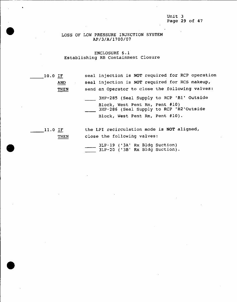
Unit 3 Page 29 of 47
LOSS OF LOW PRESSURE INJECTION SYSTEM AP/3/A/1700/07
ENCLOSURE 5.1 Establishing RB Containment Closure
10.0 IF seal injection is NOT required for RCP operation
AND seal injection is NOT required for RCS makeup,
THEN send an Operator to close the following valves:
3HP-285 (Seal Supply to RCP 'Bl' Outside
Block, West Pent Rm, Pent #10) 3HP-286 (Seal Supply to RCP 'B2'Outside
Block, West Pent Rm, Pent #10).
11.0 IF the LPI recirculation mode is NOT aligned,
THEN close the following valves:
3LP-19 ('3A' Rx Bldg Suction) 3LP-20 ('3B' Rx Bldg Suction).

Unit 3 Page 30 of 47
LOSS OF LOW PRESSURE INJECTION SYSTEM AP/3/A/1700/07
ENCLOSURE 6.1 Establishing RB Containment Closure
12.0 IF the RB radiation monitors are out-of-service,
THEN secure the sample pump:
12.1 Close the following valves:
3PR-8 (RB Radiation Monitor Inlet)
3PR-10 (RB Radiation Monitor Return Block).
13.0 IF CC is secured,
THEN close 3CC-8 (CC Return Penetration Outside Block).
14.0 IF the ILRT is in progress,
THEN notify Performance to isolate:
* Penetration #45 (ILRT Instrument Line)
* Penetration #51 (ILRT Pressurization Line).
15.0 IF EFDW is NOT required for DHR,
THEN send an Operator to close 3FDW-301 (SG '3A' Wet
Layup Recirc Inlet, East Pent Rm, Pent #50).

Unit 3 Page 31 of 47
LOSS OF LOW PRESSURE INJECTION SYSTEM AP/3/A/1700/07
ENCLOSURE 6.1 Establishing RB Containment Closure
16.0 IF the RB Cooling Units are NOT in service,
THEN isolate LPSW:
16.1 Close the following valves:
3LPSW-16 ('3A' RBCU Inlet)
3LPSW-19 ('3B' RBCU & Aux Fan Clr Inlet)
3LPSW-22 ('3C' RBCU Inlet)
3LPSW-18 ('3A' RBCU Outlet)
3LPSW-21 ('3B' RBCU & RB Aux Fan Clr Outlet)
3LPSW-24 ('3C' RBCU Outlet)
16.2 Send an Operator to close the following valves:
3LPSW-241 (RBCU '3A' Outlet to 3RIA-31/35, East
Pent Rm, Pent #34)
3LPSW-258 (RBCU '3A' Outlet Test Connection, East
Pent Rm, Pent #34)
3LPSW-242 (RBCU '3B' Outlet to 3RIA-31/35, East
Pent Rm, Pent #35)
3LPSW-259 (RBCU '3B' Outlet Test Connection, East
Pent Rm, Pent #35)
3LPSW-243 (RBCU '3C' Outlet to 3RIA-31/35, East
Pent Rm, Pent #33)
3LPSW-257 (RBCU '3C' Outlet Test Connection, East
Pent Rm, Pent #33).
17.0 IF RCPs are NOT operating,
* AND the RB fire hose stations are NOT intact,
THEN close the following valves:
3LPSW-6 (RCP Coolers Supply)
3LPSW-15 (RCP Coolers Outlet).

Unit 3 Page 32 of 47
LOSS OF LOW PRESSURE INJECTION SYSTEM AP/3/A/1700/07
ENCLOSURE 6.1 Establishing RB Containment Closure
18.0 IF all personnel using BA have evacuated the RB,
THEN send an Operator to close 3BA-271 (RB Header
Isolation, East Pent Rm, Pent #48).
19.0 IF IA pressure to the RB is lost,
THEN send an Operator to close 31A-90 (RB Header
Isolation, East Pent Rm, Pent #41).
END
Unit 3 Page 33 of 47
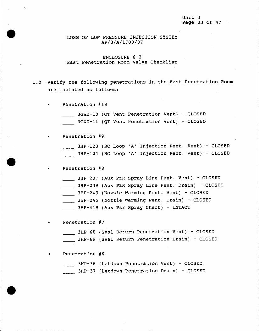
LOSS OF LOW PRESSURE INJECTION SYSTEM AP/3/A/1700/07
ENCLOSURE 6.2 East Penetration Room Valve Checklist
1.0 Verify the following penetrations in the East Penetration Room
are isolated as follows:
* Penetration #18
3GWD-10 (QT Vent Penetration Vent) - CLOSED
3GWD-11 (QT Vent Penetration Vent) - CLOSED
* Penetration #9
3HP-123 (RC Loop 'A' Injection Pent. Vent) - CLOSED
3HP-124 (RC Loop 'A' Injection Pent. Vent) - CLOSED
* Penetration #8
3HP-237 (Aux PZR Spray Line Pent. Vent) - CLOSED
3HP-239 (Aux PZR Spray Line Pent. Drain) - CLOSED
3HP-243 (Nozzle Warming Pent. Vent) - CLOSED
3HP-245 (Nozzle Warming Pent. Drain) - CLOSED
3HP-419 (Aux Pzr Spray Check) - INTACT
* Penetration #7
3HP-68 (Seal Return Penetration Vent) - CLOSED
3HP-69 (Seal Return Penetration Drain) - CLOSED
* Penetration #6
3HP-36 (Letdown Penetration Vent) - CLOSED
3HP-37 (Letdown Penetration Drain) - CLOSED
01

Unit 3 Page 34 of 47
LOSS OF LOW PRESSURE INJECTION SYSTEM AP/3/A/1700/07
ENCLOSURE 6.2 East Penetration Room Valve Checklist
* Penetration #2
3FDW-117 ('3A' SG Sample Pent. Vent) - CLOSED
3FDW-118 ('3A' SG Sample Pent. Drain) - CLOSED
* Penetration #23
3HP-202 (RCP 'A2' Seal Supply Pent. Vent) - CLOSED
3HP-204 (RCP 'A2' Seal Supply Pent. Drain) - CLOSED
3HP-209 (RCP 'Al' Seal Supply Pent. Vent) - CLOSED
3HP-211 (RCP 'Al' Seal Supply Pent. Drain) - CLOSED
3HP-390 (RCP 'Al' Seal Supply Check) - INTACT
*__ 3HP-454 (RCP 'A2' Seal Supply Check) - INTACT
* Penetration #22
3LPSW-144 (LPSW Return Pent. Drain) - CLOSED
3LPSW-145 (LPSW Return Pent. Vent) - CLOSED
3LPSW-146 (LPSW Return Pent. Test Gauge) - CLOSED
* Penetration #21
3LPSW-141 (LPSW Supply Pent. Drain) - CLOSED
3LPSW-142 (LPSW Supply Pent. Vent) - CLOSED
3LPSW-143 (LPSW Supply Pent. Test Gauge) - CLOSED
Penetration #15
3LP-44 ('A' Header Pent. Test) - CLOSED
3LP-17 ('A' LPI Injection) - INTACT

Unit 3 Page 35 of 47
LOSS OF LOW PRESSURE INJECTION SYSTEM AP/3/A/1700/07
ENCLOSURE 6.2 East Penetration Room Valve Checklist
* Penetration #50
3FDW-130 (Aux FDW Header '3A' Pent. Vent) - CLOSED
3FDW-131 (Aux FDW Header '3A' Pent. Drain) - CLOSED
3FDW-39 ('3A' SG Emer Header Check) - INTACT
3FDW-317 (EFWP Disch to SG '3A' Check) - INTACT
3CCW-121 (Aux Service Water to SG '3A' Check) - INTACT
* Penetration #38
3CS-17 (QT Return Pent. Drain) - CLOSED
3CS-18 (QT Return Pent. Vent) - CLOSED
3CS-11 (QT Recirc Pent. Check) - INTACT
* Penetration #3
3CC-24 (Supply Hdr Pent. Isolation Check) - INTACT
* Penetration #61
3PR-25 (RB Sample Outlet Test) - CLOSED
* Penetration #46
3FW-64 (Booster Pump Header Pent. Block) - CLOSED
* Penetration #60
3PR-23 (RB Sample Inlet Pent. Test) - CLOSED
3PR-68 (Radiation Monitor Inlet Drain) - CLOSED
* Penetration #45 (Located between MFDW lines)
3LRT-25 (RB Pressure Line Outer Block) - CLOSED
3LRT-36 (LRT Block Valve) - CLOSED
3LRT-38 (LRT Outer Isolation) - CLOSED

Unit 3 Page 36 of 47
LOSS OF LOW PRESSURE INJECTION SYSTEM AP/3/A/1700/07
ENCLOSURE 6.2 East Penetration Room Valve Checklist
* Penetration #20
3PR-27 (RB Purge Exhaust Pent. Test) - CLOSED
* Penetration #44
3CC-76 (CRD Cooling Pent. Outside Check) - INTACT
* Penetration #25
3FDW-46 ('3B' SG Normal Header Check) - INTACT
* Penetration #27
3FDW-247 (FDW Header '3A' Vent Block) - CLOSED
3FDW-37 ('3A' SG Normal Header Check Valve) - INTACT
2.0 Contact the control room for additional assignments prior to
exiting the penetration room.
01

Unit 3 Page 37 of 47
LOSS OF LOW PRESSURE INJECTION SYSTEM AP/3/A/1700/07
ENCLOSURE 6.3 West Penetration Room Valve Checklist
1.0 Close the following valves located in the West Penetration Room:
* Penetration #59
3CF-7 (CF Bleed to Waste Holdup Tank) - CLOSED
3CF-19 (CF Sample Block) - CLOSED
* Penetration #58
3RC-49 (PZR Sample Pent. Vent) - CLOSED
3RC-50 (PZR Sample Pent. Drain) - CLOSED
3FDW-122 ('3B' SG Sample Pent. Vent) - CLOSED
___ 3FDW-123 ('3B' SG Sample Pent. Drain) -CLOSED
* Penetration #39
3CF-35 (CF Vent to Waste Gas Filter Block) - CLOSED
3CF-36 (CF Vent to Vent Hdr Block) - CLOSED
3CF-37 (CF Vent to Vent Hdr Pent.Vent) - CLOSED
3CF-41 ('B' CFT Pressure Gauge Block) - CLOSED
3HP-156 (CFT 'B' Fill) - CLOSED
3CA-29 (Boric Acid Supply to CFT '3B') - CLOSED
3N-131 (CFT 'B' Supply Check) - INTACT
* Penetration #56
3SF-60 (Canal Fill Pent. Block) - CLOSED
* Penetration #55
3DW-59 (Demin Header Pent. Isolation) - CLOSED

Unit 3 Page 38 of 47
LOSS OF LOW PRESSURE INJECTION SYSTEM AP/3/A/1700/07
ENCLOSURE 6.3 West Penetration Room Valve Checklist
* Penetration #54
3CC-54 (Return Penetration Drain) - CLOSED
3CC-55 (Return Penetration Vent) - CLOSED
3CC-56 (Return Penetration Test) - CLOSED
* Penetration #10
3HP-216 (RCP 'B2' Seal Supply Pent. Vent) - CLOSED
3HP-218 (RCP 'B2' Seal Supply Pent. Drain) - CLOSED
3HP-223 (RCP 'Bl' Seal Supply Pent. Vent) - CLOSED
3HP-225 (RCP 'Bl' Seal Supply Pent. Drain) - CLOSED
Penetration #53
3CF-47 ('A' CFT Pressure Gauge Isolation) - CLOSED
3HP-155 (CFT 'A' Fill) - CLOSED
3CA-27.(Boric Acid Supply to CFT '3A') - CLOSED
3N-263 (Pent. Isolation LP Header) - CLOSED
3N-129 (CFT 'A' Supply Check) - INTACT
Penetration #52
3HP-149 (RC Loop 'B' Injection Pent. Vent) - CLOSED
3HP-150 (RC Loop 'B' Injection Pent. Drain) - CLOSED
* Penetration #19
3PR-29 (RB Purge Supply Pent. Test) - CLOSED

Unit 3 Page 39 of 47
LOSS OF LOW PRESSURE INJECTION SYSTEM AP/3/A/1700/07
ENCLOSURE 6.3 West Penetration Room Valve Checklist
* Penetration #51
3LRT-17 (Pressurization Isolation) - CLOSED
2" Blind Flange Installed
3LRT-54 (Pressure Gauge Isolation) - CLOSED
* Penetration #16
3LP-43 ('B' Header Pent. Test). - CLOSED
3LP-18 ('3B' LP Injection) - INTACT
NOTE: If the Security enclosure is not open, assume 3FDW-442 is * intact.
* Penetration #17
3FDW-442 (EFDW to 'B' SG Outside Check) - INTACT
2.0 Contact the control room for additional assignments prior to exiting the penetration room.

Unit 3 Page 40 of 47
LOSS OF LOW PRESSURE INJECTION SYSTEM AP/3/A/1700/07
ENCLOSURE 6.4 Miscellaneous Valve Checklist
1.0 Close the following valves located in Rm 82/83 (LPI Pump 'A' and
LP-19/20 Valve Rooms):
* Penetration #29
3CS-23 (Component Drain Header Pent. Drain) - CLOSED
3CS-25 (Component Drain Header Pent. Test) -CLOSED
* Penetration #36
3LP-66 ('3A1 Emergency Sump Line Drain) - CLOSED
3LWD-329 (LP-19 Valve Enclosure Drain) - CLOSED
* Penetration #37
3LP-65 ('3B' Emergency Sump Line Drain) - CLOSED
3LWD-330 (LP-20 Valve Enclosure Drain) -CLOSED
* Penetration #40
3LWD-99 (Emergency Sump Drain Pent. Block) - CLOSED
* Penetration #5
3RC-164 (Post Accident Sample Valve). - CLOSED

Unit 3 Page 41 of 47
LOSS OF LOW PRESSURE INJECTION SYSTEM AP/3/A/1700/07
ENCLOSURE 6.5
Elapsed Time Until Core Boiling, Core Uncovery, and Core Damage Following Loss of DHR Capability
Assumptions
* Initial RCS/LPI Temperature = 140 0 F
* Upper SG Primary Handholes Removed To Vent RCS
* Worst Case Decay Heat (EOC)
* No Operator Action
Notes
1) "Prior To Refueling" curves-assume all fuel assemblies
in the core have experienced operation at power.
2) "After Refueling" curves assume approximately one third
of the core is new fuel.
3) Curves for "LT-5=-18" are applicable to incidents where
reactor vessel level has been reduced to the bottom of
the hot leg. Example: LPI line break.
Curves
Figure 1: Time To Core Boiling Prior To Refueling
Figure 2: Time To Core Uncovery Prior To Refueling
Figure 3: Time To Core Damage Prior To Refueling
Figure 4: Time To Core Boiling After Refueling
Figure 5: Time To Core Uncovery After Refueling
Figure 6: Time To Core Damage After Refueling

Unit 3 Page 42 of 47
LOSS OF LOW PRESSURE INJECTION SYSTEM AP/3/A/1700/07
ENCLOSURE 6.5
Elapsed Time Until Core Boiling, Core Uncovery, and Core Damage Following Loss of DHR Capability
Figure 1
Time to Core Boiling
1.7
40LT-5= 80"
I * * LT-5= 50"
* 0.400orLT-5= -18"v
L
1 00001
* 02
0 4 8 12 16 2 24
D eter Au

Unit 3 Page 43 of 47
LOSS OF LOW PRESSURE INJECTION SYSTEM AP/3/A/1700/07
ENCLOSURE 6.5 Elapsed Time Until Core Boiling, Core Uncovery, and Core Damage
Following Loss of DHR Capability
Figure 2
Time to Core Uncovery Prrtb 1
12A
LT-5= 80"
40
I 9
o LT-5= 50 "
....- - L T-5 = -148"
*~~L5 o- - - - - -0 4 111122
A t
2M 0 LT-5= -18"
1AU
0A 0 4 8 12 16 3 24

Unit 3 Page 44 of 47
LOSS OF LOW PRESSURE INJECTION SYSTEM AP/3/A/1700/07
ENCLOSURE 6.5 Elapsed Time Until Core Boiling, Core Uncovery, and Core Damage
Following Loss of DHR Capability
Figure 3
Time to Core Damage
LT-5=80" 12A------- --40
I
LT-5=50"
A .. LT, 5 4100
10-*.. LT-5=14"
L OA -
LT-5 418
0 4. 6 12 16 x 24
D*dhr 9"-

Unit 3 Page 45 of 47
LOSS OF LOW PRESSURE INJECTION SYSTEM AP/3/A/1700/07
ENCLOSURE 6.5
Elapsed Time Until Core Boiling, Core Uncovery, and Core Damage Following Loss of DHR Capability
Figure 4
Time to Core Boiling
LT-5= 80"
g LT-5= 50"
L
0.4 212224.
0vd "

Unit 3 Page 46 of 47
LOSS OF LOW PRESSURE INJECTION SYSTEM AP/3/A/1700/07
ENCLOSURE 6.5
Elapsed Time Until Core Boiling, Core Uncovery, and Core Damage Following Loss of DHR Capability
Figure 5
Time to Core Uncovery asstang 1NOR5I
170
16A . LT-5= 80"
15- ---- 50
-145= 1
* ~~1* 7
2
- - -- - - - LT-5= 50"
11Am - - - - --
0A
-N - - - - -- LT-5= 14"
7m -
,5 .. -- - -
3A - LT-5= -18"
22 5
20 224 26 28.
ow d %W

Unit 3 Page 47 of 47
LOSS OF LOW PRESSURE INJECTION SYSTEM AP/3/A/1700/07
ENCLOSURE 6.5 Elapsed Time Until Core Boiling, Core Uncovery, and Core Damage
Following Loss of DHR Capability
Figure 6
Time to Core Damage
lii-- - ___ - - - - -- LT-5= 80"
LT-5= 50" 12A 16AU -- --- -
15A - LT-5= 50"
* 14A 3
o12A.3 LT-5= 14"
I
8A -* a a a3
'7A" 6A-- - LT-5= -18"1
4A.3 3
0 3 fl24 26N
Related Documents


![PRESSURE LOSS - DEC INTERNATIONAL · 2.2 BENDS The pressure loss of a bend can be determinated with the following formula: p = the pressure loss [Pa] =the resistance coefficient of](https://static.cupdf.com/doc/110x72/5f1296987038130c255e47a1/pressure-loss-dec-international-22-bends-the-pressure-loss-of-a-bend-can-be-determinated.jpg)