HAL Id: hal-01891309 https://hal.archives-ouvertes.fr/hal-01891309 Submitted on 9 Oct 2018 HAL is a multi-disciplinary open access archive for the deposit and dissemination of sci- entific research documents, whether they are pub- lished or not. The documents may come from teaching and research institutions in France or abroad, or from public or private research centers. L’archive ouverte pluridisciplinaire HAL, est destinée au dépôt et à la diffusion de documents scientifiques de niveau recherche, publiés ou non, émanant des établissements d’enseignement et de recherche français ou étrangers, des laboratoires publics ou privés. Challenges in designing very small jet engines - fuel distribution and atomization Fabian Fuchs, Vitus Meidinger, Nicolas Neuburger, Thorsten Reiter, Magnus Zündel, Andreas Hupfer To cite this version: Fabian Fuchs, Vitus Meidinger, Nicolas Neuburger, Thorsten Reiter, Magnus Zündel, et al.. Challenges in designing very small jet engines - fuel distribution and atomization. 16th International Symposium on Transport Phenomena and Dynamics of Rotating Machinery, Apr 2016, Honolulu, United States. hal-01891309

Welcome message from author
This document is posted to help you gain knowledge. Please leave a comment to let me know what you think about it! Share it to your friends and learn new things together.
Transcript

HAL Id: hal-01891309https://hal.archives-ouvertes.fr/hal-01891309
Submitted on 9 Oct 2018
HAL is a multi-disciplinary open accessarchive for the deposit and dissemination of sci-entific research documents, whether they are pub-lished or not. The documents may come fromteaching and research institutions in France orabroad, or from public or private research centers.
L’archive ouverte pluridisciplinaire HAL, estdestinée au dépôt et à la diffusion de documentsscientifiques de niveau recherche, publiés ou non,émanant des établissements d’enseignement et derecherche français ou étrangers, des laboratoirespublics ou privés.
Challenges in designing very small jet engines - fueldistribution and atomization
Fabian Fuchs, Vitus Meidinger, Nicolas Neuburger, Thorsten Reiter, MagnusZündel, Andreas Hupfer
To cite this version:Fabian Fuchs, Vitus Meidinger, Nicolas Neuburger, Thorsten Reiter, Magnus Zündel, et al.. Challengesin designing very small jet engines - fuel distribution and atomization. 16th International Symposiumon Transport Phenomena and Dynamics of Rotating Machinery, Apr 2016, Honolulu, United States.�hal-01891309�
Challenges in designing very small jet engines - fuel distribution and atomizationFabian Fuchs1,2*, Vitus Meidinger1, Nicolas Neuburger1, Thorsten Reiter1, Magnus Zündel1, Andreas Hupfer2
ISROMAC 2016
International Symposium on
TransportPhenomena and
Dynamics of Rotating Machinery
Hawaii, Honolulu
April 10-15, 2016
AbstractThe contents of this publication deal with experimental and numerical investigation of combustion chambers used in very small jet engines (VSJE) in the thrust range less than 1000 N. The Institute for Flight Propulsion of the Technische Universität München (TUM) in cooperation with the research group ‘Hummingbird – TUM Gas Turbines’ operates several test rigs for VSJEs and their components. One special test rig offers the opportunity to investigate standalone combustion chambers without influencing factors of other gas turbine components. During the last years a plurality of investigations on the operating behavior and its characteristics regarding the fuel distribution, atomization and combustion has been carried out. The findings resulting from the experimental investigations are also used as a validation basis for numerical investigations – a precondition for further optimization in designing combustion chambers of VSJE.
Keywordsvery small jet engine — VSJE — micro gas turbine — fuel atomization – vaporizer stick
1 HUMMINGBIRD – TUM GAS TURBINES, Technische Universität München, 85748 Garching, Germany2 Institute for Flight Propulsion, Technische Universität München, 85748 Garching, Germany*Corresponding author: [email protected]
INTRODUCTION
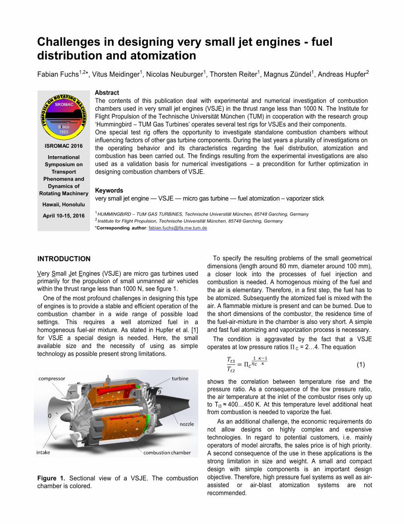
Very Small Jet Engines (VSJE) are micro gas turbines used primarily for the propulsion of small unmanned air vehicles within the thrust range less than 1000 N, see figure 1.
One of the most profound challenges in designing this type of engines is to provide a stable and efficient operation of the combustion chamber in a wide range of possible load settings. This requires a well atomized fuel in a homogeneous fuel-air mixture. As stated in Hupfer et al. [1] for VSJE a special design is needed. Here, the small available size and the necessity of using as simple technology as possible present strong limitations.
Figure 1. Sectional view of a VSJE. The combustion chamber is colored.
To specify the resulting problems of the small geometrical dimensions (length around 80 mm, diameter around 100 mm), a closer look into the processes of fuel injection and combustion is needed. A homogenous mixing of the fuel and the air is elementary. Therefore, in a first step, the fuel has to be atomized. Subsequently the atomized fuel is mixed with the air. A flammable mixture is present and can be burned. Due to the short dimensions of the combustor, the residence time of the fuel-air-mixture in the chamber is also very short. A simple and fast fuel atomizing and vaporization process is necessary.
The condition is aggravated by the fact that a VSJE operates at low pressure ratios Π C = 2…4. The equation
𝑇𝑡3
𝑇𝑡2
= Π𝐶
1𝜂𝐶
∙𝜅−1
𝜅 (1)
shows the correlation between temperature rise and the pressure ratio. As a consequence of the low pressure ratio, the air temperature at the inlet of the combustor rises only up to Tt3 ≈ 400…450 K. At this temperature level additional heat from combustion is needed to vaporize the fuel.
As an additional challenge, the economic requirements do not allow designs on highly complex and expensive technologies. In regard to potential customers, i.e. mainly operators of model aircrafts, the sales price is of high priority. A second consequence of the use in these applications is the strong limitation in size and weight. A small and compact design with simple components is an important design objective. Therefore, high pressure fuel systems as well as air-assisted or air-blast atomization systems are not recommended.

Challenges in designing very small jet engines - fuel distribution and atomization — 2
1. DESCRIPTION OF COMBUSTION CHAMBER
1.1 General Design A survey of the actual design of small gas turbine combustion chambers is presented in the following section. Almost all available VSJEs have combustion chambers with so-called vaporizer sticks following Hupfer [3]. A schematic view of the operating principle of this type of combustion chamber is shown in figure 2.
Figure 2. Schematic overview of the principle of operation of a typical VSJE combustion chamber.
Fuel is supplied by an annular fuel distributor at the back end of the combustion chamber. Divided in small tubes the fuel is injected with negligible overpressure in each tubular stick (see figure 3). Here the fuel is atomized, mixed with air and vaporized by contact with the hot surface inside the stick. Air mass flow transports the atomized and vaporized fuel to the diffuser shaped end of the stick. With the addition of excess air mass flow in the primary zone a well flammable fuel-air-mixture is generated. In this zone the flame is stabilized and a continuous combustion over a wide range of operation is possible.
Figure 3. Fuel distributor with designation of the fuel injections
Another function throughout the combustion process is to heat up the stick on the outside to offer thermal energy for the vaporization of fuel on the inside. To provide the necessary heat for the vaporization process when starting the engine, special features for igniting the combustion must be implemented. Usually a pre-combustion of easily inflammable propane gas or a special fuel igniter is used to provide the necessary heat for starting a stable combustion. In the downstream secondary zone, further air is added to the combustion and a nearly complete combustion of the injected fuel is carried out. In the last zone, the dilution zone, continued air mass flow is added to the main flow through the combustion chamber with the objective of generating a turbine-resistible temperature distribution. Limitations of this configuration are: an unbalanced fuel supply (cf. section 1.2),
an imprecise positioning of fuel injection position due todeviations which occur during mounting as well as
the resulting differences in the quality of vaporization ofthe fuel.
The position of the fuel injection is not fully adjustable in this simple injection configuration of a typical VSJE. In case of a direct contact between the outlet of the small injection tube and the stick the fuel will be injected as a film directly to the hot surface. The heat is directly transferred to the film by the hot surface and a fast vaporization is possible there. In case of an injection close to the centerline of the stick, the atomization is only supported by the air flow. The heat is transferred to the droplets only by the air. Depending on the swirl of the airflow a considerable number of droplets will leave the stick unvaporized. A swirl inside the sticks can improve atomization and vaporization because the fuel droplets are centrifuged to the hot wall. Another improvement can be reached by cutting a thread inside the stick. Due to the larger surface, roughness and sharp edges a better atomization and faster vaporization is possible. In current VSJEs, combustion chambers with 9 or 12 sticks are usually installed. There are also - mostly in older VSJEs - versions with only 6 sticks.
1.2 Functional principle and characteristics of the annular fuel distributor
In previous tests (Fuchs [4]) it was found that the fuel distribution, the combustion efficiency and the temperature profile on the circumference direction vary considerably and are inhomogeneous.

Challenges in designing very small jet engines - fuel distribution and atomization — 3
Figure 4. Percentage of the fuel mass flow deviations through the small injection tubes
It was assumed that the cause of temperature gradients is not negligible due to irregular behavior of the fuel mass flow of the individual sticks. To quantify this phenomenon, investigations on the fuel distributors on a special test bench were carried out. The measurement results confirm the fact that the fuel mass flows in the individual sticks are not identical but vary according to position, see figure 4.
Therefore different explanations are possible (for details see figure 5): As the fuel mass flow tapers from top to bottom, varying
potential affects the fuel mass flow in the individual fuelinjections. This means, a higher pressure is obtained inthe injections further below than in the injections furtherabove.
The distributor ring including the injectors aremanufactured and soldered by hand. Manufacturingdiscontinuities in insertion depth and insertion angle ofindividual injection tubes and also regarding the solderjoint are the consequences. This causes the individualinjections to jut out with unequal width and angles in thedistributor ring and hence generate varying resistanceand flow deflection losses.
The injectors were soldered on the outer surface of thedistributor ring; this means that the fuel on the uppersticks must flow “upwards” and hence there is evenlower to no potential at all compared to the injectorsfurther down.
As the supply line to the distributor ring has shifted tothe top center in all stick variations (6 till 9 stickcombustion chamber), depending on whether the supplyline is located more towards the left or right, therespective side is supplied with more fuel. This is alsoconfirmed by the diagram in figure 4: the right side of thedistributor ring, e.g. injectors 1, 2, 3, is supplied withsignificantly lower fuel mass flow.
The injectors and partly even the distributor ring arebent to a varying extent and hence have “bends” in thelines. This causes varying internal resistances.
Figure 5. Details of fuel supply
2. EXPERIMENTAL APPROACH
2.1 Experimental Setup
The Institute for Flight Propulsion of the Technische Universität München (TUM) in cooperation with the student research group ‘Hummingbird – TUM Gas Turbines’ operates a special test facility for combustion chambers for very small gas turbine engines.
Figure 6. Sectional view of the test facility around the combustion chamber (colored in brown)
-6.00%
-4.00%
-2.00%
0.00%
2.00%
4.00%
6.00%
1 2 3 4 5 6 7 8 9
Fuel
flow
dev
iatio
ns fr
om th
e av
erag
es
Stick number

Challenges in designing very small jet engines - fuel distribution and atomization — 4This test facility allows research on various chambers, due to the geometrical similarity of the different combustors in thrust range of a typical VSJE. The surrounding is equivalent to the real conditions of the gas turbine, see figure 6. In order to secure comparability of the testing results to the combustor’s behavior within the VSJE, Mach-number-similarity for the inlet flow needs to be obtained and the air to fuel ratio (AFR) has to be assimilated. The inlet’s mass flow and thereby also the flow speed through the combustor are controllable. Additionally the temperature of the incoming air can be set between ambient temperature and 400°C. The fuel mass flow and the associated AFR are adjusted through the delivery rate of the fuel pump.
Table 1. Measured values and positions
Position Measured values
3-1 Static and total pressure; Total temperature1, corresponds to Tt3
3-2 Static and total pressure; Total temperature1
3-3 Static and total pressure; Total temperature1
4 Total pressure2;Gas analysis (O2, CO2, CO, UHC)2;Total temperature1,2,3
1 Due to the low Mach-number the difference between static and total temperature is only around 2 – 3 %. Therefore, in this publication the measured recovery temperature is defined as the total temperature.
2 Position is adjustable over 360° in 5° increments. 3 Simultaneous measurements of temperatures in 5 different radial
positions
Latest projects involved the implementation of a swirl inducer, in order to analyze the effect of swirl in the inlet flow. It was investigated that the diffusor and the vanes at the end of the compressor are very highly loaded and as a result of this the flow at the inlet of the combustor is not swirl free [5]. At current state a 0°, 15° and 30° flow angle in circumferential direction can be realized (cf. Section 2.2). Previous measuring campaigns have shown the fact that the behavior of the combustion chamber is scalable regarding the variation of inlet speed, temperature and AFR. For example, a higher inlet temperature or a lower AFR (this means more fuel) affects a similar temperature profile at theoutlet in comparison to the reference results, just at a higher level in total. Due to this behavior test runs are made with ambient temperature in the inlet flow and an AFR ≈ 80 to have an unproblematic manageable testing point. 2.2. The influence of pre-swirl at the combustion
chamber inlet The following chapter shows the results of the investigation of the consequences of a pre-swirl at the inlet regarding the temperature profile and the local AFR distribution at the combustor outlet. Therefore experiments are conducted for a 0°, 15° and 30° pre-swirl.
The 9-stick combustion chamber was used for the following experiments. The Inlet conditions for the 0°- (swirl-free) and 30°-experiments are given in table 2.
Table 2. Parameters of the test runs without and with pre-swirl
Position Swirl-free
Pre-swirl of 15°
Pre-swirl of 30°
Average inlet temperature Tt3 [°C] 26.2 24.1 22.2
Average air mass flow [g/s] 102.2 103.7 102.5
Average fuel mass flow [g/s] 1.28 1.29 1.27
Average global AFR [-] 79.6 80.3 80.5
Ambient pressure [mbar] 949 941 958
The radial temperature distribution shows a remarkable difference between 0° and 30° pre-swirl, as depicted in figure 7. While the profile for swirl-free conditions does not resemblethe desired profile, which is described for example in Lefebvre [2], the temperature distribution for 30° pre-swirl shows no similarity at all. Particularly noticeable is the shift of the hotspot towards the hub in figure 7, a state, which is essential to avoid for a turbine inlet flow. This shift can be explained by an altering cooling performance. The pre-swirl leads to a gradient in static pressure due to the appearing centrifugal forces, which results in a lower cooling performance through the hub cooling holes. Although the temperature distribution for 15° pre-swirl resembles the results of the swirl-free experiment, the altering in cooling performance is still visible by the decreasingtemperature gradient near the hub. The pre-swirl also has an influence on the circumferential temperature profile as the cold area between 40° and 80° for 0° pre-swirl (see figure 8) as well as the hotspots seem to be shifted for 15° and 30° pre-swirl. An irregularity in the geometry of the combustion chamber causes an exceeding cooling for stick 9, which again induces the noticeable cold spot in figure 8. The differences in the form and dimension of the hotspots respectively the cold spot in comparison to the case without pre-swirl are mainly results of the rearrangement of the test rig. The former shown investigation of the fuel distributor indicated a high sensitivity of the fuel injection system to operations on it. Hence trying to trace the features regarding the form and dimension back to the pre-swirl is difficult. The average local AFR for all experiments is about 69.8 to 71.5. Whereas the distribution of the AFR of the 30° pre-swirlnoticeably deviates to the 0° pre-swirl case. As expected the AFR is closely connected to the temperature profile. A low AFR results in high temperatures and in turn a high AFR in low temperatures. The comparison in figure 9 reveals the same shift for the AFR as it was earlier identified for the temperature profile. The big peak for 30° pre-swirl at a position of 20° (compare figure 9) is connected with the very distinctive cold area, which again is a result of lacking fuel mass flow and vaporization. The test rig rearrangement seems to have worsened the rate of flow through the injection fuel pipe as the temperature is even lower. Special measurements have shown no remaining swirl in plane 4.

Challenges in designing very small jet engines - fuel distribution and atomization — 5
Figure 7. Profiles of radial temperature distribution at combustor outlet (measurement position 4, c.f. figure 6),without pre-swirl (top), with 15° (middle) and 30° pre-swirl (below)
Figure 8. Temperature profiles at combustor outlet (position 4, c.f. figure 6) without pre-swirl (top) and with 30° pre-swirl (below). Viewing direction is in the same direction of the flow.
0
0.2
0.4
0.6
0.8
1.0
450 475 500 525 550
no
rmal
ize
d c
han
ne
l he
igh
t [-
]
Temperature [°C]
0
0.2
0.4
0.6
0.8
1.0
450 475 500 525 550
no
rmal
ize
d c
han
ne
l he
igh
t [-
]
Temperature [°C]
0
0.2
0.4
0.6
0.8
1.0
450 475 500 525 550
no
rmal
ize
d c
han
ne
l he
igh
t [-
]
Temperature [°C]
Tt4 Average Tt4

Figure 9. Local AFR profiles at combustor outlet position 4 without pre-swirl (top) and with 30° pre-swirl (below)
3. NUMERICAL INVESTIGATIONParallel to the experimental investigation, numerical simulations were done to increase the comprehension of processes inside the combustion chamber. The chamber was modeled in CATIA V5 as a 40 degree segment, as it is shown in figure 10, with respect to the original geometry. The mesh was generated with the commercial ANSYS MESHER. For computation the ANSYS CFX V16.0 solver was used. 3.1 Used numerical models The unstructured mesh used for the numerical investigation was chosen having performed a mesh study and contains 1.3 million elements. The quality of the mesh was judged by examining specified variables, like the pressure and temperature at the outlet, over a set of meshes with different resolutions. For the simulation the RANS equations are solved and the approximations used for the governing equation is of order two. For judging the results of the calculations the convergence criteria was set to 10E-04 and the converged behavior of the examined variables. The area averaged y+ value for wall regions of importance, like the
— 6 stick wall, is 3.8 and for walls which are less important subject to the resolution of the boundary layer, 7.5.
Figure 10. Examined segment for CFD analysis
In context of the experimental investigation at a specified working point, a steady state simulation was carried out with the corresponding boundary conditions. Each wall, with exception of the stick wall, is modeled as an adiabatic wall. The inlet condition contains the total pressure and total temperature and the outlet condition the mass flow rate. The numerical model consists of several standard models implemented in the ANSYS CFX code and is described in [6]and [7]. For turbulence modelling the CFX standard ShearStressTransport-model was used, described by Menter [8]. The boundary layer is solved by using the automatic near-wall treatment, which switch automatic between wall-functions and low-Re near wall formulation. All the experiments are carried out with kerosene Jet A as fuel. This liquid fuel is modeled as a homogenous fluid with a composition of C12H23, which is a suitable simplification and rely on Rachner [9]. The gaseous fluid is modeled as an ideal, compressible mixture, and in combination with the fuel droplets as a multiphase flow. The liquid fuel droplets are modelled by the particle transport model, which tracks the particles in a Lagrangian way. Since the fuel enters the domain as a liquid fluid, models which describe the phase transformation from liquid to gaseous are needed to ensure gaseous fuel for the combustion. Therefore a particle breakup model and an evaporation model were used. The particle break up is modeled as a two stage breakup. First, directly at the entry of the Jet A liquid in the fluid (air) domain, there is a primary breakup modeled by the Blob method according to Kuensberg et al. [10]. It calculates the initial drop velocity and gives the first drop diameter equal to the nozzle diameter. Subsequently the secondary breakup is modeled by the Reitz and Diwakar Breakup Model, which includes two breakup regimes defined by local flow conditions. The two breakup regimes are the Stripping Breakup and the Bag Breakup [11]. The mass transfer from the liquid to the gaseous phase is modeled by the liquid vaporization model extended with the light oil modification. The model divides the mass transfer in two areas depending on temperature. The first one is the area where the particle temperature is below the boiling temperature and the mass transfer is driven by diffusion. The
30
40
50
60
70
80
90
100
110
120
0 40 80 120 160 200 240 280 320 360
loca
l AFR
[-]
position [°]
30
40
50
60
70
80
90
100
110
120
0 40 80 120 160 200 240 280 320 360
loca
l AFR
[-]
Position [°]
local AFR average AFR Sticks
Challenges in designing very small jet engines - fuel distribution and atomization

Challenges in designing very small jet engines - fuel distribution and atomization — 7second one is the area where the particle temperature is above the boiling temperature and the mass transfer is driven by vaporization. The combustion is modeled by the Eddy Dissipation Model, which calculates the reaction rate subject to the molar concentration ratio according to Magnussen and Hjertager [12]. The radiation is modeled with the P1 Modell, where the walls are modeled as a blackbody and the fluid domain as a grey body. This model is needed due to the high temperature of the walls of the inner combustion chamber. The particle wall interaction is modeled with simple restitution coefficients for particles. 3.2 Capabilities of the model An important feature of the model is the evaporation of the liquid Jet A by contact with the inner wall of the evaporation stick. Figure 11 shows the ideal case of the operating process in the inner combustion chamber. It includes the main components, injection and evaporation of liquid Jet A, the combustion of the gaseous fuel-air mixture and heat transfer through the stick wall to ensure the evaporation of incoming liquid Jet A to protect the combustion against extinction. This operating process can be reproduced by the simulation in a stable manner, which is the requirement for the numerical investigation of this combustion chamber type.
Figure 11. Sectional view of the simulated temperature in the combustion chamber
3.3 Comparison of simulation and experiment The whole temperature level in the simulation and the experiment is quite similar, but the maximum local temperature in the simulation is clearly higher. Therefore, a normalization of the temperature by the maximum local temperature (given by the material limitation) of the respective data set is established, in order to generate a better comparability as seen in figure 12. This normalization is obtained by
𝜏 = �̅�4,𝑖
𝑇4,𝑚𝑎𝑥,𝑖
The influence of cooling air shows a greater effect in the numerical simulation than in the experiment. Considerable quenching regions near the inner and outer combustor wall are clearly visible. An area with low temperature at 75% channel height which is caused through the last row of cooling holes in the simulated results exists. In contrast, the experimental results do not show such a significant influence
of the cooling holes, or cannot be recorded due to the limited radial range of the thermocouples at positions next to the walls. The radial positions of the local temperature maximum from the experiment and simulation are close to each other. The existing difference is caused by the strong influence of the cooling air at a high radius. The shape of the experimental radial temperature profile is kind of a damped version of the profile of the simulation. This could be a result of the simplification in 2-phase-simulation and the adiabatic wall condition, which prevent the heat flux through the wall and cause a higher gradient in the temperature profile.
Figure 12. Comparison of radial temperature profilebetween results from numerical simulation and experimental investigation
The simulation is able to provide some qualitative results to evaluate the geometry, with respect to the differences named above. So the simulation can be used as a tool to evaluate the global temperature level, the position of the maximum total temperature and to estimate the radial total temperature profile. However, the chosen simple approach without detailed information about the fuel atomization, film formation and vaporization inside the sticks does not deliver reasonable results in local temperature distribution.
4. RESULT AND PROPOSALS FOR FUTUREIMPROVEMENTS
As illustrated by the results in this publication, future modifications on the combustion chamber should concern fuel distribution. Due to the temperature profiles shown in figure 8 a much more homogeneous profile would allow a higher average combustion chamber outlet temperature without increasing the local loads and stresses for the turbine parts. Therefore a uniform distribution and inlet flow of the fuel vapor-air-mixture is necessary. As a first step, the air-fuel-mixture distribution and the vaporization in the sticks will be improved. A modification ensures that every fuel drop will get contact with the heated inside wall of the stick. Additionally a special geometry is employed to try to eliminate the punctual inlet flow of the vaporized air-fuel-mixture by converting the tube geometry to

Challenges in designing very small jet engines - fuel distribution and atomization — 8a closed ring geometry (figure 13). As a second step the airflow through the sticks will be improved. An introduced swirl should increase the contact between fuel and stick wall and guarantee the complete and quick vaporization. Consequently a shorter design of the sticks and thereby of the whole combustion chamber will be possible.
Figure 13. New design of injection system for an increasing vaporization and a more homogenoustemperature profile.
5. CONCLUSIONIn actual realized VSJE combustion chambers a high potential for optimization of the whole combustion process is possible. As shown in this publication several improvements are necessary to increase the efficiency of this type of combustion chamber. It starts with a more homogeneous distribution of the fuel atomized in the sticks and a following improved vaporization of the fuel. But for the temperature profile of the turbine inlet some modifications are appropriate. For this purpose some changes at the compressor outlet are also needed to decrease the influence of the swirl of the inlet combustion air flow and to optimize the hub cooling of the turbine. A more homogeneous distribution of temperature allows a higher thermodynamic turbine inlet temperature Tt4 without increasing maximum local temperature loads of turbine parts. This can be used for a more efficient and/or more powerful engine [13]. Nevertheless the simple and compact system of VSJE’s should be maintained for all new concepts.
ACKNOWLEDGEMENTS
The authors are greatly indebted to the Institute for Flight Propulsion (TUM) and the members of the research group ‘Hummingbird’. The successful experimental and numericalwork would not be possible without this support.
NOMENCLATURE
Identifier: VSJE very small jet engine TUM Technische Universität München AFR air- to fuel-ratio UHC O2 CO2 CO Ti pi Π𝐶 κ ηc
concentration of unburned hydrocarbons concentration of oxygen concentration of carbon dioxideconcentration of carbon monoxidetemperatur at station i pressure at station i compressor pressure ratio isentropic exponent compressure efficiency
Indices: t 0…9 max (r)
total values station designation (cf. figure 1 & 6) maximum circumferential average on defined radii
REFERENCES [1]
[2]
[3]
[4]
[5]
A. Hupfer, W. Erhard and H.-P. Kau, Investigation of Combustor Concepts for Micro Gas Turbine Jet Engines, 23rd International Symposium on Transport Phenomena, Auckland NZ, 2012 A. H. Lefebvre, D. R. Ballal, Gas Turbine Combustion: Alternative Fuels and Emissions, 3rd edition, CRC Press, Taylor and Francis Group, Boca Raton, FL, 2010. A. Hupfer, Experimental Investigation of Performance Parameters of Very Small Jet Engine Combustors, 25 th
International Symposium on Transport Phenomena, Krabi TH, 2014 F. Fuchs, Technical Report (LFA-2015-019), Institute for Flight Propulsion, TU München, Munich DE, 2015 A. Mayer, M. Naubert, Technical Report (LFA-2011-007), Institute for Flight Propulsion, TU München, Munich DE, 2011
[6]
[7]
[8]
[9]
[10]
[11]
[12]
[13]
Ansys CFX-Solver Theory Guide, Release 16.0, Canonsburg, U.S.A: Ansys, Inc., 2013 Ansys CFX-Solver Modeling Guide, Release 16.0, Canonsburg, U.S.A: Ansys, Inc., 2013 F.R. Menter, Zonal two Equation k-w Turbulence Models for Aerodynamic Flows, Eloret Institute, Sunnyvale, 1993M. Rachner, Stoffeigenschaften von Kerosin Jet A-1, Mitteilung 98-01, Deutsches Zentrum für Luft- und Raumfahr, 1998 S.C. Kuensberg, S.-C. Kong and R.D. Reitz, Modelling the Effects of Injector Nozzle Geometry on Diesel Sprays, SAE Paper 1999-01-0912, 1999 R.D. Reitz and R. Diwakar, Structur of High-Pressure Fuel Sprays, SAE Technical Paper, 870598, 1987 B.F. Magnussen and B.H: Hjertager, On math. Modeling of Turbulent Combustion with special Emphasis on Soot Formation and Combustion, 1977 A. Hupfer, D. Hirndorf, Investigation of Parameters Affecting the Thermodynamic Cycle of Very Small Jet Engines, 15th International Symposium on Transport Phenomena and Dynamics of Rotating Machinery, ISROMAC, 2014
Related Documents