DDEC IV ON-HIGHWAY - EGR APPLICATION AND INSTALLATION 7 TOOLS Section Page 7.1 D IAG NO S TIC R EQUEST SW ITCH ........................................................ 7-3 7.2 VEHICLE ELECTRON IC PRO G RAMMING SYSTEM ............................ 7-5 7.3 D IAG NO S TIC DATA READER ................................................................ 7-7 7.4 D ETROIT DIESEL DIAG NO STIC LINK .................................................. 7- 11 7.5 D DEC R EP RO G RAMMING SYSTEM .................................................... 7- 13 7.6 D DEC E NG INE PROTECTIO N S IMULATIO N K IT .................................. 7- 19 7.7 D DEC M AN UA LS .................................................................................... 7- 21 All information subject to change without notice. (Rev. 8/03) 7-1 7SA743 0305 Copyright © 2003 DETROIT DIESEL CORPORATION

Welcome message from author
This document is posted to help you gain knowledge. Please leave a comment to let me know what you think about it! Share it to your friends and learn new things together.
Transcript
DDEC IV ON-HIGHWAY - EGR APPLICATION AND INSTALLATION
7 TOOLS
Section Page
7.1 D IAG NO S TIC R EQUEST SW ITCH ........................................................ 7-3
7.2 VEHICLE ELECTRON IC PRO G RAMMING SYSTEM ............................ 7-5
7.3 D IAG NO S TIC DATA READER ................................................................ 7-7
7.4 D ETROIT DIESEL DIAG NO STIC LINK .................................................. 7- 11
7.5 D DEC R EP RO G RAMMING SYSTEM .................................................... 7- 13
7.6 D DEC E NG INE PROTECTIO N S IMULATIO N K IT .................................. 7- 19
7.7 D DEC M AN UA LS .................................................................................... 7- 21
All information subject to change without notice. (Rev. 8/03) 7-17SA743 0305 Copyright © 2003 DETROIT DIESEL CORPORATION

TOOLS
THIS PAGE INTENTIONALLY LEFT BLANK
7-2 All information subject to change without notice. (Rev. 8/03)7SA743 0305 Copyright © 2003 DETROIT DIESEL CORPORATION
DDEC IV ON-HIGHWAY - EGR APPLICATION AND INSTALLATION
7.1 DIAGNOSTIC REQUEST SWITCH
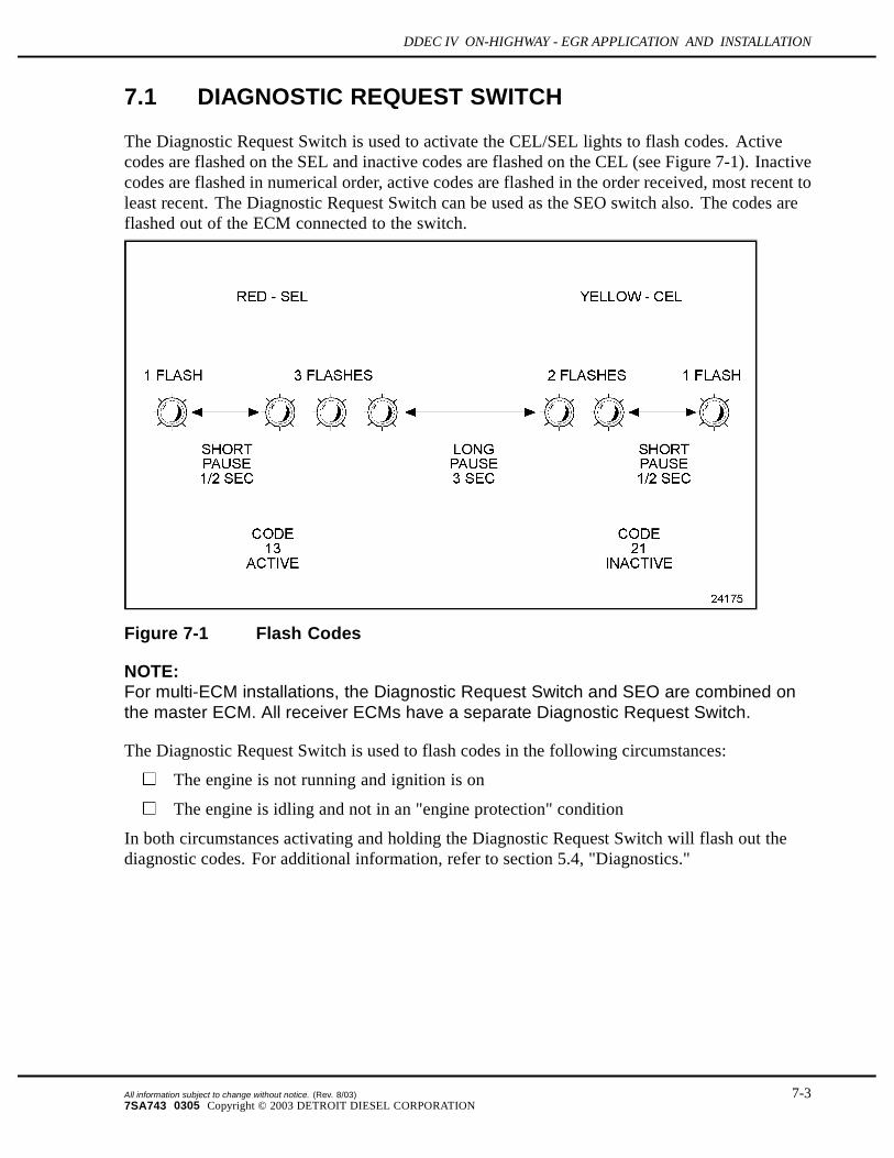
The Diagnostic Request Switch is used to activate the CEL/SEL lights to flash codes. Activecodes are flashed on the SEL and inactive codes are flashed on the CEL (see Figure 7-1). Inactivecodes are flashed in numerical order, active codes are flashed in the order received, most recent toleast recent. The Diagnostic Request Switch can be used as the SEO switch also. The codes areflashed out of the ECM connected to the switch.
Figure 7-1 Flash Codes
NOTE:For multi-ECM installations, the Diagnostic Request Switch and SEO are combined onthe master ECM. All receiver ECMs have a separate Diagnostic Request Switch.
The Diagnostic Request Switch is used to flash codes in the following circumstances:
The engine is not running and ignition is on
The engine is idling and not in an "engine protection" condition
In both circumstances activating and holding the Diagnostic Request Switch will flash out thediagnostic codes. For additional information, refer to section 5.4, "Diagnostics."
All information subject to change without notice. (Rev. 8/03) 7-37SA743 0305 Copyright © 2003 DETROIT DIESEL CORPORATION

TOOLS
THIS PAGE INTENTIONALLY LEFT BLANK
7-4 All information subject to change without notice. (Rev. 8/03)7SA743 0305 Copyright © 2003 DETROIT DIESEL CORPORATION
DDEC IV ON-HIGHWAY - EGR APPLICATION AND INSTALLATION
7.2 VEHICLE ELECTRONIC PROGRAMMING SYSTEM
The purpose of the DDEC Vehicle Electronics Programming System (VEPS) is to give OEMsthe ability to configure many ECM parameters. This allows DDEC features to be tailored to thespecific customer requirements when the vehicle is assembled. Some of the features whichmay be configured by VEPS are the transmission type, cruise control, vehicle speed limit, idleshutdown, rating switches, digital inputs, and digital outputs.
7.2.1 SOFTWARE
The VEPS PC software package consists of the several files which are extracted when thesoftware installation program is executed. A System Users Manual which defines the availableparameters is included with the software package at the time of purchase.
The PC interface utilizes a communications driver which is defined in the TMC RecommendedPractice RP1210A. The RP1210A software is used to translate the datalink signal of the ECM tothe format required by Windows programs. The RP1210A communications driver is included aspart of the VEPS software package.
7.2.2 HARDWARE
The hardware portion of the VEPS programming package includes the interface module andcables. The components that are included in the package are listed in Table 7-1.
Part Description Part Number100 Foot Cable 23512893
SAE J1708 6-Pin Dash Connector 23515957
J1708/RS-232 Translator Box 23512415
6 foot Cable 23515869
Table 7-1 VEPS Hardware
A cable kit, listed in Table 7-2, is also available.
Part Description Part NumberCable Kit
(includes the 100 foot cable and the 6-pin dash connector)23512980
Table 7-2 VEPS Cable Kit
All information subject to change without notice. (Rev. 8/03) 7-57SA743 0305 Copyright © 2003 DETROIT DIESEL CORPORATION

TOOLS
A translator and cable kit, listed in Table 7-3, is also available.
Part Description Part NumberTranslator Kit
(includes the J1708/RS-232 translator box, 100 foot cableand the 6-pin dash connector)
23512895
Table 7-3 VEPS Translator and Cable Kit
The VEPS software kit, listed in Table 7-4, is available.
Part Description Part NumberSoftware Kit
(includes the RP1202 Software and the VEPS Software)Contact DDC Application Engineering
Table 7-4 VEPS Software Kit
7-6 All information subject to change without notice. (Rev. 8/03)7SA743 0305 Copyright © 2003 DETROIT DIESEL CORPORATION

DDEC IV ON-HIGHWAY - EGR APPLICATION AND INSTALLATION
7.3 DIAGNOSTIC DATA READER
The hand-held DDR plugs into the Diagnostic Data Link Connector located in the VehicleInterface Harness (refer to section 3.10.4). This connection allows the DDR to receive datafrom the ECM. The DDR is used to display:
Engine Description via the ENGINE DATA LIST menu
Codes via the DIAGNOSTIC CODES menu
View/reprogram certain operating parameters
A printout of the information displayed on the DDR can be obtained by attaching a printer.
NOTE:Suite 8 is required for Rel 33.0 software and later.
7.3.1 REQUIREMENTS
The components and part numbers are listed in Table 7-5. Also see Figure 7-2.
Component Part NumberPro-Link Plus with Case 108004
Multi Protocol Cartridge (MPC) 208040
Detroit Diesel Application Suite 8 PC Card, DDEC III/IV 802015
Detroit Diesel MPC PCMCIA Manual 901012
Power and Data Cable (2 pc) 501002
Data Cable Only 501003
Power Cable Only 501004
PC Terminal Cable 8 ft 501005
6–pin Deutsch Adapter w/Atart End 408024
9–pin Deutsch Adapter w/Atari End 408028
6–pin and 9–pin Deutsch Adapter w/Atari End 408048
Storage Case 217003
Table 7-5 Diagnostic Data Reader/Pro-Link® Components and Part Numbers
Pro-Link® is a registered trademark of Micro Processor Systems, Inc.
All information subject to change without notice. (Rev. 8/03) 7-77SA743 0305 Copyright © 2003 DETROIT DIESEL CORPORATION

TOOLS
NOTE:Printers used in Europe must use a European power supply as listed in Table 7-6. Do notsubstitute an AC adapter for the European power supply.
Component Part NumberPro-Link Printer with Serial Adapter & AC Adapter 178001
Pro-Link Printer with 220–240 V Euro Adapter 171007
Printer AC Adapter 178003
Thermal Paper — 5 rolls 171002
Printer Battery Pack 178004
Euro Power Supply Only 400058
Table 7-6 DDR/Pro-Link® Printers and Power Supply
Figure 7-2 Pro-Link Plus/Diagnostic Data Reader Components
7-8 All information subject to change without notice. (Rev. 8/03)7SA743 0305 Copyright © 2003 DETROIT DIESEL CORPORATION
DDEC IV ON-HIGHWAY - EGR APPLICATION AND INSTALLATION
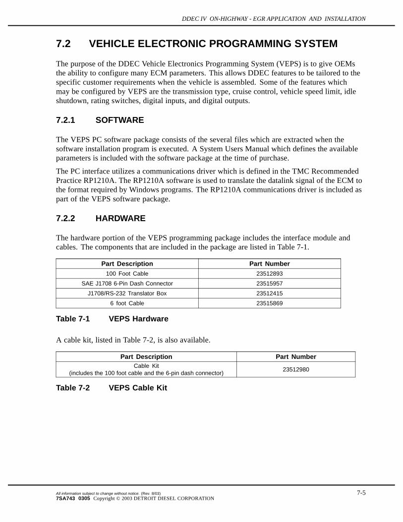
To avoid injury from loss of vehicle/vessel control, theoperator of a DDEC equipped engine must not attempt to useor read the Diagnostic Data Reader when the vehicle/vesselis moving.
The DDR can be purchased from:
Nexiq TechnologiesPhone: 1-800-639-6774www.nexiq.com
All information subject to change without notice. (Rev. 8/03) 7-97SA743 0305 Copyright © 2003 DETROIT DIESEL CORPORATION

TOOLS
THIS PAGE INTENTIONALLY LEFT BLANK
7-10 All information subject to change without notice. (Rev. 8/03)7SA743 0305 Copyright © 2003 DETROIT DIESEL CORPORATION

DDEC IV ON-HIGHWAY - EGR APPLICATION AND INSTALLATION
7.4 DETROIT DIESEL DIAGNOSTIC LINK
The Detroit Diesel Diagnostic Link® (DDDL)is a sophisticated PC software package supportingthe setting up, maintenance and repair of engines using the DDEC IV ECM. For additionalinformation, refer to the on-line Help within the program.
7.4.1 CALIBRATION
You can use the DDDL to:
Read and display the current calibration from an ECM.
Create a calibration for the ECM on an individual engine.
Save a single calibration with an ECM password so that the same calibration can be usedconveniently for a fleet of vehicles with the same password, or can be used by a technicianwho does not have access to the password.
Change the engine rating of a vehicle.
Set the injector calibration when you replace the injectors.
View an audit trail of ECM and injector calibration changes.
7.4.2 DIAGNOSTICS AND MAINTENANCE
You can use the Detroit Diesel Diagnostic Link to:
Monitor a wide range of parameters while connected live to the ECM .
Select a group of these parameters and plot how they have varied over the last two minutes.
Take and save a snapshot of how the parameters vary over a period of time, so that you canreplay the snapshot for detailed analysis.
Monitor fault codes as they occur while connected live to the ECM. You can also clear anyinactive fault codes stored in the ECM.
Take a snapshot recording the fault codes occurring over a period of time, and relate theiroccurrence to the values of measurements made by the ECM.
Test for the effect on performance of cutting out individual cylinders.
View a record of the injector timings.
Set the ECM output functions to particular values to support troubleshooting.
Display specific troubleshooting help for any fault codes that occur, or have occurred.
View engine and trip totals, and reset the trip counters in the ECM.
Reset the ECM counters monitoring component usage when you replace the components.
All information subject to change without notice. (Rev. 8/03) 7-117SA743 0305 Copyright © 2003 DETROIT DIESEL CORPORATION

TOOLS
THIS PAGE INTENTIONALLY LEFT BLANK
7-12 All information subject to change without notice. (Rev. 8/03)7SA743 0305 Copyright © 2003 DETROIT DIESEL CORPORATION
DDEC IV ON-HIGHWAY - EGR APPLICATION AND INSTALLATION
7.5 DDEC REPROGRAMMING SYSTEM
The DDEC Reprogramming System (DRS) is composed of Programming Software, DDECcommMainframe Communications software, all the hardware required to connect a Personal Computerto the ECM, and a user manual explaining the use of the software. The DRS software is used toreprogram calibrations, modify customer calibration values, upgrade ECM software versions,update injector calibration codes, and program blank ECMs. The DDECcomm software isused to communicate via modem to the DDC Mainframe computer which stores all the DDECCalibrations.
7.5.1 REQUIREMENTS
The DRS and DDECcomm software require a Personal Computer which meets certain minimumrequirements. These minimum requirements include a pentium microprocessor with 16 MB ofRAM, a modem, and the Windows 95 Operating System. DDC also sells kits which include aLaptop PC, please contact your Detroit Diesel representative for current Laptop specifications.
7.5.2 DRS WELCOME SCREEN
There are several choices on the Welcome Screen. The following sections describe these menuoptions.
Program ECM
Reprogram ECMs with a customer calibration that has previously been downloaded from theDDC mainframe computer. The customer configurable parameters are retained through thistype of a reprogramming.
Program Fleet ECM
Reprogram fleet units from a single customer calibration that has previously been downloadedfrom the DDC mainframe computer. The customer configurable parameters are retained throughthis type of a reprogramming.
Program ECM With Mainframe Data
Reprogram ECMs with a customer calibration that has previously been downloaded from theDDC mainframe computer. Unlike the standard Program ECM option, this option will overwritethe customer configurable parameters, resulting in a calibration exactly like the one createdby the factory.
Display Customer Calibration
Displays electronic parameter settings currently programmed in an ECM.
All information subject to change without notice. (Rev. 8/03) 7-137SA743 0305 Copyright © 2003 DETROIT DIESEL CORPORATION
TOOLS
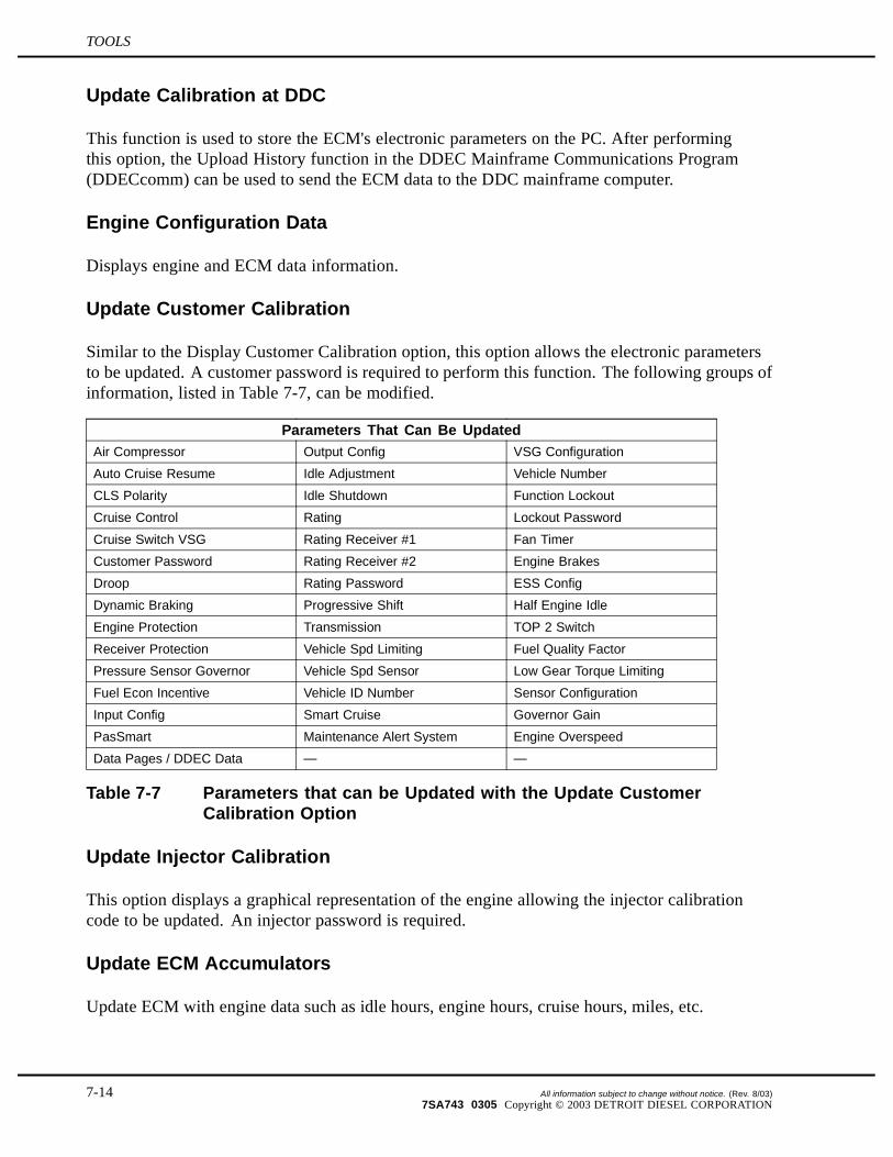
Update Calibration at DDC
This function is used to store the ECM's electronic parameters on the PC. After performingthis option, the Upload History function in the DDEC Mainframe Communications Program(DDECcomm) can be used to send the ECM data to the DDC mainframe computer.
Engine Configuration Data
Displays engine and ECM data information.
Update Customer Calibration
Similar to the Display Customer Calibration option, this option allows the electronic parametersto be updated. A customer password is required to perform this function. The following groups ofinformation, listed in Table 7-7, can be modified.
Parameters That Can Be UpdatedAir Compressor Output Config VSG Configuration
Auto Cruise Resume Idle Adjustment Vehicle Number
CLS Polarity Idle Shutdown Function Lockout
Cruise Control Rating Lockout Password
Cruise Switch VSG Rating Receiver #1 Fan Timer
Customer Password Rating Receiver #2 Engine Brakes
Droop Rating Password ESS Config
Dynamic Braking Progressive Shift Half Engine Idle
Engine Protection Transmission TOP 2 Switch
Receiver Protection Vehicle Spd Limiting Fuel Quality Factor
Pressure Sensor Governor Vehicle Spd Sensor Low Gear Torque Limiting
Fuel Econ Incentive Vehicle ID Number Sensor Configuration
Input Config Smart Cruise Governor Gain
PasSmart Maintenance Alert System Engine Overspeed
Data Pages / DDEC Data — —
Table 7-7 Parameters that can be Updated with the Update CustomerCalibration Option
Update Injector Calibration
This option displays a graphical representation of the engine allowing the injector calibrationcode to be updated. An injector password is required.
Update ECM Accumulators
Update ECM with engine data such as idle hours, engine hours, cruise hours, miles, etc.
7-14 All information subject to change without notice. (Rev. 8/03)7SA743 0305 Copyright © 2003 DETROIT DIESEL CORPORATION

DDEC IV ON-HIGHWAY - EGR APPLICATION AND INSTALLATION
DDC Mainframe Communications
This option is used to select DDECcomm to communicate with the server.
Print ECM Parameters
This menu item queries the ECM for the Customer Calibration information and formats it into areport which can be printed out on a printer attached to the parallel port on the computer.
7.5.3 DRS MENU OPTIONS
Other functions available from the pull-down menu at the top of the screen are listed below.
Upgrade ECM Software
New versions of DDEC ECM software may be programmed into customer's ECMs with thisoption. There is a nominal charge each time this function is performed.
Reset Customer Calibration
Same function as update customer calibration.
Change Passwords
Allows changes to the customer, group lockout, or rating password.
Random Customer Password
This option creates a random customer calibration password.
Random Rating Password
This option creates a random rating password.
Random Lockout Password
This option creates a random lockout password.
Display Available ECM S/W Versions
Displays ECM software versions that are available on the PC. These versions are used toelectronically upgrade ECM software for DDEC III and IV.
All information subject to change without notice. (Rev. 8/03) 7-157SA743 0305 Copyright © 2003 DETROIT DIESEL CORPORATION

TOOLS
Display Station Log File
Displays a file containing system usage information.
Display Downloaded Units
This menu item displays the Unit Numbers of the engines which have been downloaded from themainframe and are available for programming.
Comms Setting
This option allows changes to the comms protocol, interface hardware being used, and thebaud rate.
Options
This option allows entry of the application ID for connecting to the DDC server.
7.5.4 DDECCOMM
DDECcomm is a Win95 program which can be invoked by selecting the DDEC Server Interfaceicon on the Windows desktop or through the Start button via Programs | DDEC ElectronicControls | DDEC Communications. The following menu options are available in this program.
Download Engine Serial Calibration(s)
This option is used to download any changed or desired unit calibrations from the DDCmainframe computer. These calibrations are stored on the PC for a maximum of 14 days, afterthat period they are automatically deleted.
Download Fleet Calibration(s)
This option allows the download of a single "fleet" unit from the mainframe to the PC. This"fleet" unit calibration may be used to program multiple units in a fleet via the Program FleetECM option discussed above.
Upload History
This option takes the programming history on the PC and uploads it to the DDC mainframe.This allows DDC to maintain a current image of the calibration status should further service berequired. The history file must first be created by running the Update Calibration at DDC menuoption in the DRS Programming Software.
7-16 All information subject to change without notice. (Rev. 8/03)7SA743 0305 Copyright © 2003 DETROIT DIESEL CORPORATION
DDEC IV ON-HIGHWAY - EGR APPLICATION AND INSTALLATION
Display Available ECM S/W Versions
Displays ECM software versions that are available on the PC. These versions are used toelectronically upgrade ECM software for DDEC III and IV.
Display Station Log File
Displays a file containing system usage information.
Display Downloaded Units
This menu item displays the Unit Numbers of the engines which have been downloaded from themainframe and are available for programming.
Update Logon Parameters
This option is used to configure mainframe logon and network settings. All user informationmay be updated when this option is selected.
All information subject to change without notice. (Rev. 8/03) 7-177SA743 0305 Copyright © 2003 DETROIT DIESEL CORPORATION

TOOLS
THIS PAGE INTENTIONALLY LEFT BLANK
7-18 All information subject to change without notice. (Rev. 8/03)7SA743 0305 Copyright © 2003 DETROIT DIESEL CORPORATION

DDEC IV ON-HIGHWAY - EGR APPLICATION AND INSTALLATION
7.6 DDEC ENGINE PROTECTION SIMULATION KIT
The DDEC Engine Protection Simulation Kit is used to reduce diagnostic troubleshooting timefor DDEC sensors. The normal use for these false sensors is to simulate an engine fault thatwould result in the engine protection system triggering a code in the DDEC ECM. This kit canalso be used for testing and verification of the engine shutdown system, fan control outputs,and coolant level outputs. This will also be useful in simulating an engine protection fault toshow customers how the DDEC protection system will react in the event of a failure that wouldnormally cause damage to the engine.
To use, plug the simulator into the connector currently used for the appropriate sensor. Start andrun the engine and DDEC will trigger the appropriate code for that fault.
The DDEC Engine Protection Simulation Kit components and part numbers are listed in Table 7-8.
Component Part NumberCoolant Low Level Simulator 23524785
High Oil/Coolant Temperature Simulator 23524787
Low Oil Pressure Simulator 23524786
Table 7-8 DDEC Engine Protection Simulation Kit, P/N: 23526923
The High Crankcase Pressure Simulator (P/N: 23524784) is for the Series 4000 only and is notincluded in kit.
7.6.1 COOLANT LEVEL LOW SIMULATOR
This simulator is preset to advise the ECM that the coolant is low. Use only for DDEC III orIV. This simulator can be used to:
Verify protection function.
Test low coolant level light output to ensure it is configured to the correct output andcorrect polarity (activates the output).
Determine if the actual sensor is bad/shorted. A bad/shorted CLS can result in otherfault codes.
7.6.2 HIGH OIL/COOLANT TEMPERATURE SIMULATOR
This simulator is preset to provide a 250 F (121 C) signal to the ECM. Use for any DDEC. Thissimulator can be used to:
Test coolant temperature shutdown logic/protection.
Test oil temperature shutdown logic/protection.
Test coolant temperature high output.
Test oil temperature high output.
Fake coolant temperature high to test fan control circuit.
All information subject to change without notice. (Rev. 8/03) 7-197SA743 0305 Copyright © 2003 DETROIT DIESEL CORPORATION

TOOLS
Fake oil temperature high to test fan control circuit.
7.6.3 LOW OIL PRESSURE SIMULATOR
This simulator is preset to provide oil pressure signal of 0 psi (0 kPa). This simulator canbe used to:
Provide a known pressure (oil pressure) for engine protection testing.
Provide a known pressure (fuel pressure) for fault code testing.
Provide a known pressure (coolant pressure) for engine protection testing.
Verify if correct output is configured for low oil pressure (activates the output).
Test current OPS to determine if a shorted sensor is causing other codes.
Test current FPS to determine if a shorted sensor is causing other codes.
Test current CPS to determine if a shorted sensor is causing other codes.
7.6.4 HIGH CRANKCASE PRESSURE SIMULATOR (SERIES 4000 ONLY)
The High Crankcase Pressure Simulator (P/N: 23524784) is not included in the kit. This simulatoris preset to provide a crankcase pressure signal of 12 psi / 83 kPa.
7-20 All information subject to change without notice. (Rev. 8/03)7SA743 0305 Copyright © 2003 DETROIT DIESEL CORPORATION

DDEC IV ON-HIGHWAY - EGR APPLICATION AND INSTALLATION
7.7 DDEC MANUALS
The following DDC manuals provide more information about troubleshooting and specificDDEC features:
Construction & Industrial EDM and AIM Installation and Troubleshooting (7SA801)
Construction & Industrial EDM and AIM User Manual (6SE710)
ProDriver DC User Manual(6SE703)
Electronic Fire Commander Installation and Troubleshooting (6SE476)
Optimized Idle - DDEC III/IV - Installation and Troubleshooting (7SA741)
DDEC III/IV Single ECM Troubleshooting (6SE497)
IRIS User and Installation Guide(6SE0036)
Ether Start Installation (7SA727)
All information subject to change without notice. (Rev. 8/03) 7-217SA743 0305 Copyright © 2003 DETROIT DIESEL CORPORATION

TOOLS
THIS PAGE INTENTIONALLY LEFT BLANK
7-22 All information subject to change without notice. (Rev. 8/03)7SA743 0305 Copyright © 2003 DETROIT DIESEL CORPORATION
Related Documents