- 5 - “Knowledge is of two kinds: we know a subject ourselves, or we know where we can find information upon it.” ~ Samuel Johnson (English Poet, Critic and Writer. 1709-1784) Chapter 2 COLOR VIDEO PROCESSING With the advent of novel digital display technologies, color processing is increasingly becoming a key aspect in consumer video applications. Consumers demand more vivid, crisp and natural pictures without any visual artifacts. Modern digital display systems require significantly more advanced color imaging techniques than what was adequate ten or fifteen years ago. Larger screen size, higher luminance and higher resolution of today’s displays require sophisticated color and image reproduction techniques. While the display end of the video processing chain has undergone revolutionary change over the past decade, image capture capability of video cameras has also improved, along with the signal rate in the rest of the video processing pipeline, making it feasible to achieve the high quality color and image reproduction as we see today [Kim 2005]. Such development has not been possible in all aspects of video processing. The requirement of backward compatibility of the receivers imposed serious restriction on adopting new scanning formats that could lead to higher resolution, wider gamut and superior depth perception. However, at the same time, this constraint has stimulated innovative solutions without sacrificing compatibility. One compelling example is the introduction of color television in the sixties [de Haan 2007]. This compatibility issue essentially underscores the significance of various video standards in video processing.

Welcome message from author
This document is posted to help you gain knowledge. Please leave a comment to let me know what you think about it! Share it to your friends and learn new things together.
Transcript

- 5 -
“Knowledge is of two kinds: we know a subject ourselves, or we know where we can find information upon it.” ~ Samuel Johnson (English Poet, Critic and Writer. 1709-1784)
Chapter 2
COLOR VIDEO PROCESSING
With the advent of novel digital display technologies, color processing is increasingly becoming
a key aspect in consumer video applications. Consumers demand more vivid, crisp and natural
pictures without any visual artifacts. Modern digital display systems require significantly more
advanced color imaging techniques than what was adequate ten or fifteen years ago. Larger
screen size, higher luminance and higher resolution of today’s displays require sophisticated
color and image reproduction techniques. While the display end of the video processing chain
has undergone revolutionary change over the past decade, image capture capability of video
cameras has also improved, along with the signal rate in the rest of the video processing pipeline,
making it feasible to achieve the high quality color and image reproduction as we see today
[Kim 2005]. Such development has not been possible in all aspects of video processing. The
requirement of backward compatibility of the receivers imposed serious restriction on adopting
new scanning formats that could lead to higher resolution, wider gamut and superior depth
perception. However, at the same time, this constraint has stimulated innovative solutions
without sacrificing compatibility. One compelling example is the introduction of color television
in the sixties [de Haan 2007]. This compatibility issue essentially underscores the significance
of various video standards in video processing.

- 6 -
This chapter starts with a description of the color specifications in various video standards,
including color primaries and color coding standards. While the focus of this research is color
and contrast enhancement in video (and also still images), various other processing not directly
related to color or contrast significantly affect the overall picture quality. Thus, this chapter
includes a review of various processes typical of a video processing chain in consumer video
applications. These processes are independent of any specific display technology, and so have
been classified as display-independent video processing. Various modern display technologies
necessitate additional color and image processing, which are essentially display-dependent
processing. To appreciate the state of the art, the working principles for various modern display
devices, as well as special video processing techniques employed in some of these devices, have
been briefly reviewed along with appropriate references for a detailed discussion. The
concluding section takes a fresh look at the way color is handled in video processing, and how
color science can be used to improve color quality in consumer video applications.
2.1 Color Specifications in Video Standards
In one of the early publications on HDTV colorimetry, DeMarsh [DeMarsh 1990] pointed out
that the emerging display technologies presented an opportunity to improve the color quality of
television images. Three potential areas were identified for colorimetric improvement in
television systems, i) defining color characteristics, ii) extending color gamuts to take advantage
of the newer display technologies, and iii) inclusion of constant luminance operation, which
ensures conveying luminance information to the fullest extent in a television system.
Accordingly, color specifications in video standards can be classified into three parts, namely,
specification of color primaries and the white point, specification of the Opto-Electronic Transfer

- 7 -
Functions (OETFs), and specification of color coding for the compression and transmission of
color information.
Before describing these color specifications, it is important to differentiate between standard-
definition television (SDTV) and high-definition television (HDTV). This classification is based
on resolution and scanning format.
There are two main scanning formats in SDTV, formats with 480 active pixel lines with
interlacing and a frame rate of 29.97 Hz (denoted as 480i or 480i29.97) and 576 active pixel
lines with interlacing and a frame rate of 25 Hz (denoted as 576i or 576i25). 480i systems with
4:3 aspect ratio (ratio of width to height of the displayed image) can have a resolution of
640x480, 704x480 or 720x480. 576i systems with 4:3 aspect ratio can have a resolution of
768x576 or 720x576 or 948x576. Widescreen 16:9 format supports resolutions 720x483 and
720x576.
On the other hand, HDTV has higher resolution, typically 0.75 million pixels or more [Poynton
2003]. Most common HDTV formats are 1280x720 with progressive scanning at a frame rate of
60 Hz (denoted as 720p or 720p60) and 1920x1080 with progressive or interlaced scanning at a
frame rate of 24 (only progressive) or 30 Hz (1080p30/1080i30, 1080p24/1080p30). 1080p60
and 1080p120 formats are also possible. The aspect ratio in HDTV is 16:9.

- 8 -
2.1.1 Color Primaries
The set of colorants used for a particular coloration process is referred to as a primary set [Berns
2000]. Except for some state-of-the-art technologies, most displays use three primaries, namely
red, green and blue. All video standards describe color primaries in terms of the chromaticites of
RGB and the white point (an achromatic color with highest luminance achievable in a given
system), and thereby the color gamut of any device that complies with a given standard. Color
gamut describes the range of colors produced by a coloration system [Berns 2000], including
displays. Color primaries defined in various widely known standards are discussed below
[Poynton 2003]:
CIE: CIE color primaries were defined in CIE 1931 standard observer. CIE Illuminant B was
defined as the white point. CIE primaries are no longer used in video coding or reproduction.
NTSC: In 1958, National Television System Committee (NTSC) standardized color primaries,
primarily to be used for color Cathode-Ray Tube (CRT) displays. The white point has the
chromaticities of CIE Illuminant C. The NTSC primaries were chosen such that largest color
gamut could be achieved with the commercially available phosphors for CRT monitors. These
primaries and the white point are no longer used in displays, but NTSC specification is still used
as the industry benchmark. Compared to NTSC compliant displays of the past, modern CRTs
have brighter and more efficient phosphors, even though NTSC displays produced more
saturated red and yellow [Susstrunk 1999].

- 9 -
EBU Tech 3213: In 1975, European Broadcasting Union (EBU) published a standard for
chromaticity tolerances for studio monitors conforming to 576i SDTV systems (standard-
definition televisions with 576 active picture lines and interlaced scanning), known as EBU
Tech. 3213. D65 was used as the white point.
SMPTE RP 145: Society of Motion Pictures and Television Engineer (SMPTE) set color
standards for 480i SDTV systems (standard-definition televisions with 480 active picture lines
and interlaced scanning) and early 1035i30 HDTV systems (high-definition televisions with
1035 active picture lines, 29.97 frame rate and interlaced scanning). This standard also uses D65
as white point.
ITU-R BT 709/sRGB: In 1990, International Telecommunication Union’s Radiocommunication
Sector (ITU-R) recommended standard primaries for high-definition television (HDTV),
formally known as ITU-R BT 709, or simply Rec. 709. The Rec. 709 primaries are incorporated
into the sRGB specifications widely used in the computing and computer graphics community,
but sRGB uses D50 white point, while Rec. 709 uses D65. These primaries are the most widely
used color primaries for studio video and modern display systems. Note that displays using Rec.
709 primaries have a color gamut that is 71% of the standard NTSC color gamut obtained from
conventional CRT displays [Ok 2005].
Adobe RGB: These primaries were designed to provide large color gamut with RGB as the
working space, and were based on SMPTE-240M standard and later renamed as Adobe RGB 98

- 10 -
[Susstrunk 1999]. The primaries have been adopted in some of the modern wide gamut CRT
and LCD displays [Kwak 2005].
Table 2.1 lists the chromaticities of the color primaries defined by various standards. Note that
x+y+z = 1, thus z can be easily calculated from the given data. Figure 2.1 plots some of these
primaries on the chromaticity diagram.
Table 2.1 Color primaries used in video processing
Red Green Blue White Point
x y x y x y Illuminant x y
CIE 0.7347 0.2653 0.2737 0.7174 0.1665 0.0089 B 0.3484 0.3516
NTSC 0.67 0.33 0.21 0.71 0.14 0.08 C 0.31 0.316
EBU Tech. 3213
0.64 0.33 0.29 0.6 0.15 0.06 D65 0.3127 0.329
SMPTE RP 145
0.63 0.34 0.31 0.595 0.155 0.07 D65 0.3127 0.329
ITU-R BT 709
0.64 0.33 0.3 0.6 0.15 0.06 D65 0.3127 0.329
sRGB 0.64 0.33 0.3 0.6 0.15 0.06 D50 0.3457 0.3585
Adobe RGB 0.64 0.34 0.21 0.71 0.15 0.06 D65 0.3127 0.329

- 11 -
Fig. 2.1 Color primaries defined in various video standards [Source: Susstrunk 1999, Fig. 7]
A 3x3 matrix transformation can be used to convert from one set of primaries to another. For
example, the following equation can be used to convert CIE XYZ to Rec. 709 primaries
[Poynton 2003]:
!
R709
G709
B709
"
#
$ $ $
%
&
' ' '
=
3.2405 (1.5372 (0.4985
(0.9693 1.876 0.042
0.0556 (0.2040 1.0573
"
#
$ $ $
%
&
' ' '
X
Y
Z
"
#
$ $ $
%
&
' ' '
(2.1)
Other primaries can similarly be obtained.
2.1.2. Opto-Electronic Transfer Functions (OETFs)
Opto-Electronic Transfer Function (OETF) refers to the intrinsic nonlinear function in a CRT
display that converts the input voltage to luminance. Gamma correction in video cameras
essentially pre-compensates for this nonlinearity and achieves perceptual coding at the same time

- 12 -
[Poynton 2003]. Various video standards have defined the transfer function differently. As
mentioned earlier, Rec. 709 is the international standard for HDTV. The transfer function
specified by Rec. 709 is also used as SDTV studio standard. The transfer function specified for
encoding is linear with a slope of 4.5 below a linearized signal value of 0.018, and follows an
exponential curve above between 0.018 and 1, as shown below:
!
" V =4.5L 0# L # 0.018
1.099L0.45 $ 0.099 0.018# L # 1
% & '
(2.2)
Here, V´ is nonlinear gamma corrected signal, R´, G´ or B´. Equation (2.3) can be inverted to
decode the signal and retrieve original RGB values as follows:
!
L =
" V
4.50# " V # 0.081
" V + 0.099
1.099
$
% &
'
( )
1
0.45
0.081# " V # 1
*
+
, ,
-
, ,
(2.3)
These definitions do not take into account any display specific tone scale alterations. L and
!
" V in
above equations are normalized to unity. However, when represented in 8-bits, the values are
scaled between 16 and 235 to allow for headroom above reference white and footroom below
reference black, which are necessary to accommodate filter overshoot and undershoot
respectively [Poynton 2003].
This and other transfer functions defined by various standards are discussed in detail in [Poynton
2003].

- 13 -
2.1.3. Color Coding Standards
This section outlines various color coding standards followed in the industry, details of which are
beyond the scope of this thesis, but are available in [Poynton 2003].
Signal coding in video systems involve three steps as described below:
Step 1 – Gamma correction: A nonlinear transfer function is applied to each of the linear R, G
and B signals. This function, often called gamma correction, is comparable to a square root and
takes care of the nonlinearity in the conventional CRT display. Gamma correction results in
nonlinear signals denoted as R´, G´ and B´. Since human visual system is sensitive to luminance
changes over a wide range of luminance values, nonlinear image coding needs to be used to
achieve perceptual uniformity. The nonlinear transfer function gamma is used to approximate
our lightness perception. Note that in encoding, gamma correction is used before converting
RGB to an opponent based color space. This is important from engineering standpoint, to reduce
computational complexity in the decoding stage.
Step 2 – Formation of luma and chroma signals: From the nonlinear signals R´, G´ and B´,
luma component Y´ and color difference components (B´- Y´) and (G´- Y´) are formed. Note
that the term luma is used to differentiate this component from luminance. Y´ computations for
SDTV (as per Rec. 601) and HDTV (as per Rec. 709) are as follows:
!
601 " Y = 0.299 " R + 0.587 " G + 0.114 " B (2.4)
!
709 " Y = 0.2126 " R + 0.7152 " G + 0.114 " B (2.5)

- 14 -
In component digital video, MPEG and Motion-JPEG, the color difference components are
scaled to form CB and CR respectively.
Step 3 – Chroma subsampling: The color difference components are subsampled. Chroma
subsampling is the process of reducing data capacity needed to transmit color information, while
maintaining full luma information. This takes advantage of the relatively low sensitivity of our
visual system to detect color differences compared to luminance. Chroma subsampling does not
typically result in a perceptual loss of chromatic details in video, but is the key source of artifacts
resulting from color processing in video.
Different schemes are available for chroma subsampling. If we consider a 2x2 pixel array of
R´G´B´ components, converting the nonlinear RGB to Y´CBCR will result in 12 bytes of data in
8-bit systems. This is denoted as 4:4:4 Y´CBCR. In 4:2:2 sampling included in Rec. 601 for
studio digital video, the color difference components are subsampled horizontally by a factor of
2, with CB and CR being coincident with even numbered Y´ samples. This consumes 8 bytes,
instead of 12. In 4:1:1 scheme, CB and CR are subsampled horizontally by a factor of 4, and
coincide with every fourth Y´ sample. This scheme requires 6 bytes only. In 4:2:0 sampling
scheme used in JPEG, H-261, MPEG-1, MPEG-2 etc, CB and CR are subsampled both
horizontally and vertically each by a factor of 2. Thus, there is one set of CB and CR components
for the four Y´ samples. The number of bytes used in this case is also 6.
SDTV color coding: Studio applications require that full 8-bit range (between 0-255) not be
used for luma scaling so as to leave a headroom and footroom to accommodate higher output

- 15 -
resulting from filter operation and misadjusted equipment. In an 8-bit system, offsets of 16 and
128 are added to the luma and chroma signals respectively. Luma reference levels are 16 and
235, and chroma reference levels are 16 and 240. Digital values 0 and 255 are used in the video
data only for synchronization purposes. Following equation is used for computing 8-bit Rec. 601
Y´CBCR from gamma corrected digital counts normalized between 0 and 1:
!
" Y
CB
CR
#
$
% % %
&
'
( ( (
=
16
128
128
#
$
% % %
&
'
( ( (
+
65.481 128.553 24.966
)37.797 )74.203 112
112 )93.786 )18.214
#
$
% % %
&
'
( ( (
" R
" G
" B
#
$
% % %
&
'
( ( (
(2.6)
HDTV color coding: As mentioned before, ITU-R Rec. BT.709 standard is the most commonly
used standard for HDTV. Rec. 709 Y´CBCR can be computed from R´G´B´ using the following
equation:
!
" Y
CB
CR
#
$
% % %
&
'
( ( (
=
16
128
128
#
$
% % %
&
'
( ( (
+
46.559 156.629 15.812
)25.664 )86.336 112
112 )101.730 )10.270
#
$
% % %
&
'
( ( (
" R
" G
" B
#
$
% % %
&
'
( ( (
(2.7)
NTSC and PAL color coding: NTSC (acronym for National Television System Committee) and
PAL (acronym for Phase Alternating Line) coding are also known as composite coding, where
quadrature modulation is applied to combine two color difference components into a modulated
chroma signal, which is then added to the luma signal through frequency interleaving to form a
composite signal. Composite decoding breaks the composite signal into constituent luma and
chroma signals. A composite signal enabled the use of new color receivers in early sixties to
receive black and white broadcast, and thus providing required backward compatibility to the
color television sets. However, these coding schemes are not generally used anymore due to the

- 16 -
resulting artifacts, and also because of the availability of adequate bandwidth to carry component
signals as in Rec. 601 and Rec. 709.
2.2 Display-Independent Video Processing
The components of a typical video processing pipeline in consumer video applications are shown
in Figure 2.2 [Caviedes 2008, Klompenhouwer 2004]. Encoded signal is transmitted from a
broadcasting station and is received by the signal receiver, which then passes it to the decoding
module. The video stream then passes through various post processing routines for artifact
removal, format conversion and enhancement. Next, a color space transformation is applied in
case of different primaries for source and display formats. A gamma correction ensures correct
tone reproduction on the display, while quantization is required to obtain discreet digitized
values for each display channel signal. The processed video is then ready to be displayed on a
designated display device.
Fig. 2.2 A typical video processing pipeline in consumer video systems
Artifact Removal
Coding Artifact Removal
Noise Reduction
Spatio-Temporal Format Coversion
Spatial scaling De-interlacing
Frame-rate conversion
Enhancement Sharpness Contrast
Color Decode
Display Color Space Conversion
Gamma Correction
(Linearization)
Video source format
Display format
Quantization

- 17 -
What follows is a brief description of various processes mentioned above. A detailed treatise of
these processes is available elsewhere [de Haan 2003].
2.2.1 Artifact Removal
Noise and other degradations in video must be removed during the post-processing stage. These
degradations occur throughout the operating broadcasting chain, mainly during encoding and
transmission. Many of these degradations do not directly relate to colors in video, but it is
important to be aware of these issues, as the artifact removal is an important step in the video
processing chain. This has a significant impact on the subsequent enhancement process as well
as ultimate picture quality. The process of artifact removal can be broadly classified into two
categories, namely, coding artifact removal and noise reduction.
2.2.1.1 Coding Artifact Removal: Most of the artifacts commonly encountered in video result
from video compression, or encoding. Several encoding standards are available for video
compression. The artifacts resulting from compression depends on three factors, data source,
coding bit rates and compression algorithms. The coding artifacts can be dealt with at the
encoding end (preprocessing) or after decoding in the post processing stage, as shown in Figure
2.2. Various types of video compression artifacts are briefly described below. Detailed reviews
are available in [Shen 1997], [Yuen 1998] and [Wu 2006].
i) Blocking: Blocking effects are the discontinuities found at the boundaries of adjacent blocks
in a reconstructed frame, resulting from each block being encoded without consideration of the
correlation between adjacent blocks. This is the most common artifact that results from both
- 18 -
JPEG and MPEG compression standards and is more visible in smooth areas with low lightness,
as shown in Figure 2.3. Note that these artifacts will be further enhanced during color and
contrast enhancement.
Fig. 2.3 Blocking artifact [Source: Yuen 1998, Fig. 1]
ii) Blurring/ Color Bleeding: Blurring is the effect of a loss or smoothing of spatial details in
areas with moderate to high spatial frequencies. The perception of lack of contrast weakens as
the viewing distance increases. Blurring is associated with luminance channel, while the
corresponding effect on chrominance channels cause a smearing in the areas with a drastic
variation in the chrominance values. This is called color bleeding and is visible in Figure 2.4
around the arm.
iii) Ringing: The ringing effect is caused by a coarse quantization of high frequency components
in the frequency domain. The effect is most apparent along the high contrast edges in otherwise
smooth areas, and appears as shimmering or rippling outwards from the edge extending up to the
adjacent block boundary. Ringing effect occurs not only in the luminance channel, but also in the

- 19 -
chrominance components. In this case, the ringing appears as wave-like transitions of color
because of which colors in the affected areas do not correspond to the colors of the surrounding
areas. Chrominance ringing is coarser than luminance ringing due to the chroma subsampling
(discussed later under color coding). Figure 2.4 shows an example of color ringing, in the form
of high frequency changes around the edge of the table. The ringing effect is the most noticeable
artifact in the subband/wavelet coding schemes at low bit rates.
Fig. 2.4 Ringing and color bleeding effect [Source: Yuen 1998, Fig. 8]
iv) Staircase Effect: In block based transform coding (e.g. Discreet Cosine Transform), when a
diagonal edge extends over several consecutive blocks, coarse quantization results in a series of
horizontal or vertical steps. This is known as staircase effect. An example is shown in Figure 2.5.
It is mainly noticeable in case of small block sizes (e.g. 6x6), but for larger blocks, it appears as
occasional misalignment in an otherwise smooth edge [Yuen 1998].
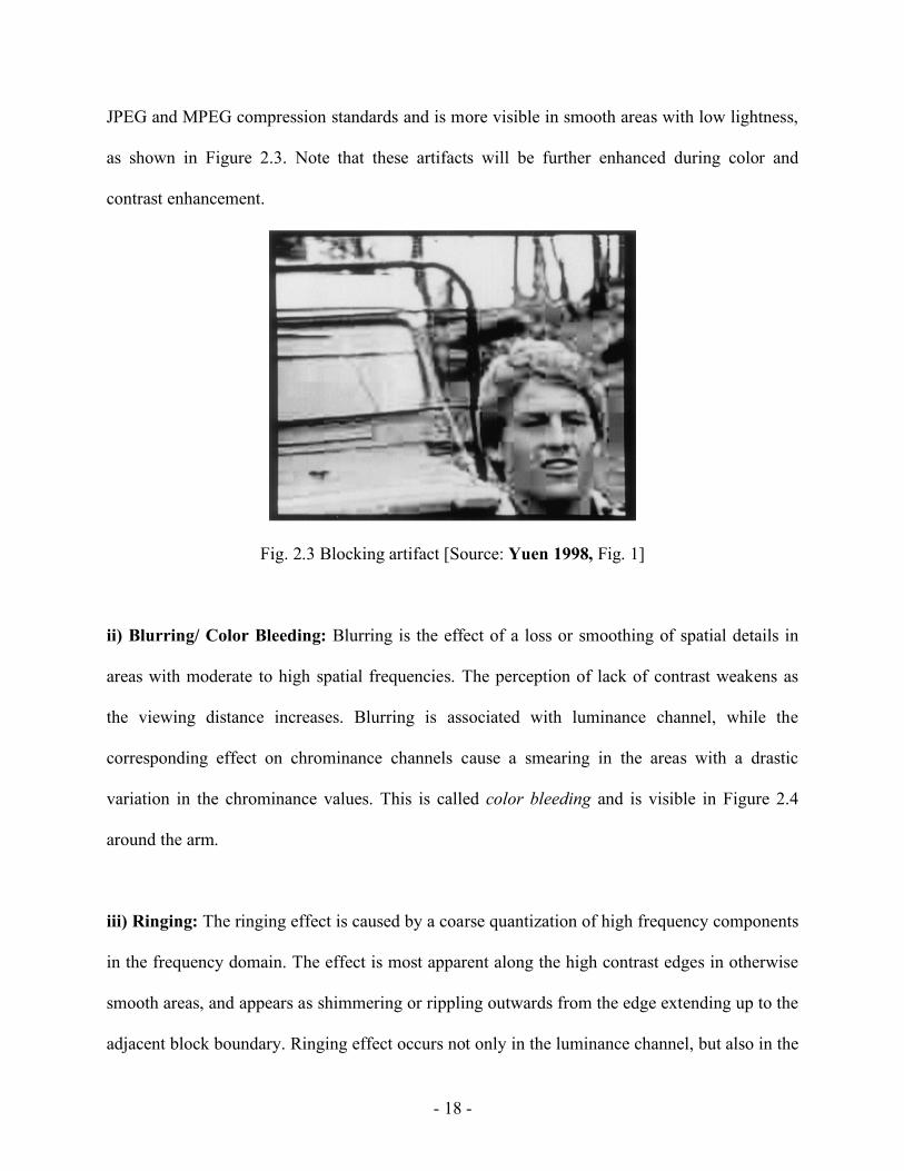
v) Mosaic Patterns: This artifact also results from block based transform coding, due to the
apparent mismatch between the contents of adjacent blocks. It manifests as a block having a
- 20 -
contour or texture dissimilar with those of the adjacent blocks. Mosaic pattern generally appears
along with the blocking effect. An example is shown in Figure 2.6.
Fig. 2.5 Staircase effect [Source: Yuen 1998, Fig. 9]
Fig. 2.6 Mosaic patterns visible on the character’s face [Source: Yuen 1998, Fig. 11]
- 21 -
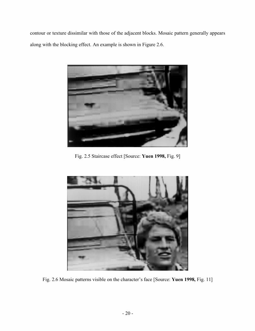
vi) False contouring: This artifact results from direct quantization of pixel values. It typically
occurs where the image has a uniform background with a color gradient, and shows up like a
series of step-like gradations in a smoothly textured area (Figure 2.7).
Fig. 2.7 False contouring [Source: Yuen 1998, Fig. 17]
vii) Motion Compensation Mismatch: Motion-compensated coding is a predictive coding
technique applied to video sequences involving motion. In other words, motion compensation
(MC) is a technique for describing a video frame in terms of transformation from a reference
frame to the current frame. Block processing assumes identical motion of all the pixels within a
given block. However, this leads to problems around the boundaries of the moving objects in a
video, as the blocks in these areas encompass both the moving objects and the stationary
background. Figure 2.8 shows an example of this artifact in the form of high frequency spatial
noise around the boundary between the arm and the background.
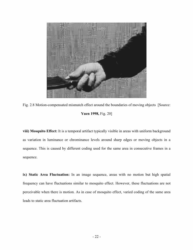
- 22 -
Fig. 2.8 Motion-compensated mismatch effect around the boundaries of moving objects [Source:
Yuen 1998, Fig. 20]
viii) Mosquito Effect: It is a temporal artifact typically visible in areas with uniform background
as variation in luminance or chrominance levels around sharp edges or moving objects in a
sequence. This is caused by different coding used for the same area in consecutive frames in a
sequence.
ix) Static Area Fluctuation: In an image sequence, areas with no motion but high spatial
frequency can have fluctuations similar to mosquito effect. However, these fluctuations are not
perceivable when there is motion. As in case of mosquito effect, varied coding of the same area
leads to static area fluctuation artifacts.
- 23 -
x) Flickering: Intensity flicker is defined as unnatural temporal fluctuations of frame intensities
that do not originate from the original scene. The flicker is a spatially localized effect that occurs
in regions of substantial size [Bovik 2005]. This is a video compression artifact and can be
caused by various factors, for example, a random noise due to digitization of the original content,
a quantization noise caused by compression, unequal quantization levels between adjacent
frames, variation in the bit rates assigned to different frames or to different areas within the same
frame etc [Shen 1997].
xi) Chrominance Mismatch: In block based coding, only luminance information is used, but
luminance correlation between blocks of pixel may not apply to chrominance information. This
may result in chrominance mismatch, manifested as a misplacement of a block in comparison
with its own color and the color of the surrounding areas in the video frame.
2.2.1.2 Noise Reduction: Noise is a form of point degradation in video. Point degradation
affects the gray level of pixels without impacting spatial details or motion. While noise generally
refers to a random process, for example, thermal noise, lightning etc, noise can also be coherent,
for example, noise due to channel cross-talk [de Haan 2003]. De Haan classifies noise into four
major categories:
Amplitude distribution: The amplitude distribution can be uniform (e.g. quantization noise),
Gaussian (e.g. thermal noise), or Poisson (quantum noise).

- 24 -
Signal dependency: Noise can be independent of the video signal (additive noise), or can be a
function of it (multiplicative noise).
Domain: Noise properties may vary along horizontal, vertical or temporal dimensions
Frequency characteristics: In any given dimension, noise may have different frequency
characteristics, for example, white noise, 1/f noise and triangular noise.
Noise reduction involves determining the correlation among pixels in an image or image
sequence, either in the spatial or in the temporal domain. It is essentially realized through noise
filtering [de Haan 2003].
2.2.2 Spatio-Temporal Format Conversion
Format conversion is essential in consumer video applications to distribute the same video
content using various video broadcasting formats, and present them simultaneously on various
modern display devices with different characteristics. Format conversion can be either spatial or
temporal, or both. The video signal represents a sequence of images, each described by the
spatial addressing format depicting the number of pixels in horizontal and vertical directions.
The number of images per second determines the temporal addressing format [Klompenhouwer
2004].
2.2.2.1 Spatial Scaling: If the number of pixels on a video line or the number of lines in an input
image does not match those of the display, spatial scaling is used to resolve this issue. An

- 25 -
example is the aspect ratio conversion employed in wide screen displays. Earlier method of
spatial scaling involved simple pixel repetition and pixel dropping, for up scaling and
downscaling respectively. While these methods are still used for format conversion in the
vertical and temporal domains, they are not preferred solutions because of the loss in the details
in the image and resulting artifacts like jagged edges. A common artifact resulting from wrong
up sampling is called “chroma bug”, appearing in the form of tiny horizontal streaks of incorrect
coloration. Contemporary methods employ poly-phase filtering for sample rate conversion,
which can be either integer scaling or fractional scaling. Integer scaling is achieved through
decimating and interpolating low-pass filters for downscaling and up scaling respectively.
Fractional or non-integer scaling applies a combined method of up sampling (by adding zero
valued samples and interpolating) and down sampling (by dropping samples from the input
signal) [de Haan 1999]. Polyphase filtering yields higher quality scaling than simple pixel
dropping, as shown in Figure 2.9. The underlying assumption in employing poly-phase filter
based sample rate conversion stems from the sampling theorem, i.e. the sampling frequency must
be more than twice the bandwidth of the input signal.
Fig. 2.9 An example of spatial sampling: down sampling by pixel dropping (left) and polyphase
filtering (right) [Source: Klompenhouwer 2004 Fig. 4]

- 26 -
2.2.2.2 De-Interlacing: Video scanning represents a sequential array of pixels used to capture,
transmit and display the content at a given frame rate. Interlacing, a scanning scheme fairly
common in conventional broadcast television and HDTV, helps reduce transmission bandwidth
without compromising resolution. In this scheme, the complete frame is broken down into two
fields, each with half of the total number of scanning lines (odd and even lines). The second field
is delayed by half the frame time from the first [Poynton 2003]. This helps achieve improved
picture quality in CRT based displays with sufficient refresh rate (to avoid perceivable flicker),
without consuming extra bandwidth. However, many modern displays like Liquid Crystal
Displays (LCD), micromirror or Digital Light Projector (DLP) and Plasma Display Panels (PDP)
use progressive scanning instead of interlacing (video processing in these devices are described
later). In this scheme, the entire frame is scanned, transmitted and displayed line by line, from
top to bottom into a single field. Thus, depending on the application, de-interlacing might be
needed for high quality video scanning format conversion.
De-interlacing can be of two types, field repetition and line repetition. Field repetition is a
temporal process where one or more fields are buffered in memory and consecutive fields are
added (weaving) or averaged (blending) to form a single frame. Line repetition is spatial and
achieved by extending each field to form the entire frame. However, de-interlacing is typically a
lossy process and leads to various artifacts. Field repetition typically leads to motion artifacts
while line repetition causes jagged edges [de Haan 2003]. Figure 2.10 shows an example of
artifacts resulting from de-interlacing on moving objects.

- 27 -
Original
Staircase artifacts resulting from de-
interlacing using line repetition
Feathering artifacts resulting from de-
interlacing using field repetition
Fig. 2.10 An example of artifacts resulting from de-interlacing [Source: Klompenhouwer 2004
Fig. 5]
Advanced de-interlacing technique employs motion estimation and compensation to avoid
motion related artifacts.
2.2.2.3 Frame-Rate Conversion: Various video sources use various frame rates (also referred to
as picture rates). Video cameras generally use 50-60 Hz, motion picture films are recorded at 24,
25 or 30 Hz, and the TV or PC displays have a frame rate between 50 and 120 Hz [de Haan
2003]. Thus, frame rate conversion may be needed before some video content can be displayed
on a given device.
One of the common methods for frame rate conversion is 2-3 pulldown, which transfers film at
24 Hz to video at 60 Hz. The first film frame is transferred to two video fields, while the second
is transferred to three, resulting in five video fields. Following frames follow the same order,
with the role of first and second fields reversed [Poynton 2003]. However, this process, or any
frame rate conversion where the difference between input and output rates is less than 30 Hz,

- 28 -
typically results in jerky motion, or motion judder as they are called, shown in Figure 2.11 [de
Haan 2003].
Fig. 2.11 Original and perceived motion in 2-3 pulldown [Source: de Haan 1999, Fig. 5]
In other cases where the difference between input and output frame rate is more than 30 Hz,
picture repetition results in motion blur. In this case, we perceive an object simultaneously at two
locations in the output video, at intermediate locations along the motion trajectory where we
expect the object to appear, and at locations where the object is repeatedly shown by the display.
This is illustrated in Figure 2.12.
As in case of de-interlacing, above problems can be remedied through motion estimation and
compensation techniques. These techniques can be implemented in a single integrated circuit [de
Haan 1999].

- 29 -
Fig. 2.12 Original and perceived motion when difference between the input and output frequency
is more than 30 Hz [Source: de Haan 1999, Fig. 6]
2.2.3 Enhancement
The quality of color reproduction in displays is usually based on the preferences of individual
viewers. Thus, the purpose of image enhancement in video is to improve the subjective picture
quality, and not a reliable reproduction of the original video content. While a systematic
improvement of the picture quality requires the knowledge of the process or processes that
degraded it in the first place, in practice, information on the prior processes the original data was
subjected to is seldom known [Poynton 2003]. Even though image enhancement processing can
be a “matter of taste”, there are certain commonly agreed upon image features that generally
enhance the image quality [de Haan 2003]. For example, a bright and colorful image with high
contrast is preferred by most observers [Kim 2005]. Image enhancement in consumer video
applications primarily aims at improving three perceptual image attributes, namely, sharpness,

- 30 -
contrast and color. The following subsections discuss common enhancement strategies for these
attributes.
2.2.3.1 Sharpness: Sharpness is the image attribute that indicates the extent to which edges and
other fine details in an image are visible. Sharpness can be enhanced by boosting the high and/or
middle frequency components in an image using linear filtering methods, also known as linear
peaking, or by edge enhancement or transient improvement. Peaking filters can be horizontal or
vertical, or both (two-dimensional). However, enhancing the diagonal frequencies in an image is
not preferable as it amplifies the noise, but does not improve perceived sharpness. Linear
peaking in general enhances the noise, which is most visible against uniform background. The
method commonly applied to prevent this noise enhancement is called coring, which introduces
an amplitude threshold below which linear peaking does not take place. The other alternative is
an adaptive peaking signal that depends on the amplitude of the high frequency content. This is
termed as dynamic peaking. In more advanced solutions, peaking is adaptive to local chroma, in
particular the skin tone. In case of skin tone, the amount of peaking is controlled to avoid
enhancing skin imperfections or introduce wrinkles.
The other method for sharpness improvement, i.e. edge enhancement, is a nonlinear process,
which involves detecting the edges and compressing their extent. When applied to the luminance
signal, this is called Luminance Transient Improvement (LTI), and when applied to chrominance
signal, this is termed as Color Transient Improvement (CTI) [de Haan 2003]. When sharpness
enhancement is conducted on chroma-subsampled content, or content with poor chroma
upscaling, it may lead to artifacts.

- 31 -
2.2.3.2 Contrast: Contrast is defined as the difference between the maximum and minimum
luminance in a stimulus divided by the sum of those two luminances [Fairchild 2005]. This is
true for images and video as well. Contrast enhancement can be global, or local. Global contrast
enhancement typically involves a nonlinear transfer function applied to the luminance channel.
Local contrast enhancement mostly involves filtering, either in the spatial domain, or in the
frequency domain.
Applying the nonlinear transfer function is generally referred to as gamma correction, the main
purpose of which is to correct for the display nonlinearity at the capture end. However, changing
the nonlinear shape also helps achieve different perceptual effects, and is typically provided as a
user control. There are various forms of black level correction applied to the transfer function,
for example, by setting the darkest part of an image to zero luminance (auto pedestal), or by
applying an additional linear transfer function with an offset and a modified gain (black restore),
or by using an offset coupled with different gains in the darker and lighter luminance ranges
(black stretch) [de Haan 2003].
The other common method for contrast improvement is histogram modification, where the
luminance values in an image are remapped to achieve a desirable distribution (the histogram).
Sometimes the histogram modification incorporates amplitude stretch, where the desirable
luminance levels in the scene are expanded to optimally use the available signal range.
Above methods mainly rely on signal processing and are not perceptual based. Various published
image processing based methods for contrast enhancements are discussed in Chapter 4.

- 32 -
2.2.3.3 Color: Ideally, the goal of color reproduction improvement in the video processing chain
is to match the primaries of the modern display system with those of the video camera used in
the capture process. Different color primaries used in video processing are discussed later in this
chapter. The problem with such color space conversion is in the application of gamma correction
during the capture process. Because of the high gamma values in modern displays (ranging
between 2.6 and 3, while cameras typically use a gamma of 2.2), red and magenta become more
saturated, while green and cyan are de-saturated, and white and the skin tone remain unaltered.
This makes it virtually impossible to go back to the original color space by a simple 3x3 matrix
transformation. What is done instead is to apply a linear conversion to correct three key colors,
for example, skin-tone, white and a natural green [de Haan 2003].
Skin tone correction involves correcting for the hue shift that sometimes occurs during the
transmission process (mainly in NTSC coding). Skin tone detection essentially looks for colors
with the hue angles falling within a predefined range, which may lead to correction of object
colors resembling skin tone (false positives), correction of various skin tones to an ideal value,
which may not be appropriate, and may even give rise to artifacts.
White correction is nothing but a modification of the white point of the color space, in color
science terminology, chromatic adaptation transform. Many modern display devices have a white
point correlated color temperature of 10000 K or higher, and thus the white point of the source
video color space needs to be appropriately converted.

- 33 -
Human visual system is quite sensitive to a saturation change of green colors. We tend to prefer
vivid, saturated green, as in grass and leaves (one of the memory colors). During the color space
conversion from the camera to the display, the green ends up being significantly de-saturated,
and sometimes undergoes a hue shift. The green enhancement involves increasing the saturation
of natural green, coupled with a hue correction.
2.3 Display-Dependent Video Processing
Since the late nineties, display processors have seen a tremendous amount of developmental
efforts. State-of-the-art processors include specialized algorithms for removing visual artifacts,
increasing the resolution by up-conversion, for color correction, enhancement etc. CRTs of
yesteryears are being replaced by flat panel displays based on various modern technologies, with
a common goal of achieving higher luminance and larger color gamut. While one of the means to
accomplish larger color gamut has been to add more primaries (Multi-Primary Display or MPD),
the other strategy involves development of new light sources, including Light Emitting Diode
(LED) and laser, with highly saturated colors. [Kim 2005].
2.3.1 Working Principles of Modern Digital Display Devices
A brief description of the working principles of various modern displays is provided below.
2.3.1.1 Liquid Crystal Display (LCD)
LCD devices take advantage of the fact that the structure of the liquid crystals can be changed by
the application of an electric field so that they transmit different amounts of light. Many LCD
devices are based on twisted nematic type of liquid crystals. Such a display consists of a layer of

- 34 -
liquid crystal molecules sandwiched between two transparent electrodes and two polarizing
filters oriented perpendicular to each other. At the end, there is a reflecting surface to send light
back to the viewer, and is replaced by a light source in case of a backlit LCD. Under normal
condition, the liquid crystals form a helical structure between the two electrodes. When a voltage
is applied across these electrodes, liquid crystal molecules are aligned along the field, with the
amount of twisting reducing proportionally with applied voltage. With sufficient voltage, the
crystals are completely untwisted and light passing through the first polarizer is blocked by the
second polarizer with crossed orientation. A zero voltage allows most amount of light to be
transmitted through the helical structure and results in white. Thus, different amounts of voltage
lead to different gray levels. Figure 2.13 shows this mechanism graphically.
Fig. 2.13 Mechanism of operation in a Liquid Crystal Display [Source:
http://www.samsungsdi.com/contents/en/tech/disClass_02_01.html]
- 35 -
A color LCD has each pixel divided into three subpixels with RGB color filters and arranged in
various geometries. Each subpixel is individually addressable through appropriate electronics.
When each row/column of the display has its own electrical circuit and the pixels are addressed
one at a time, the display is called a passive-matrix display. Displays equipped with Thin Film
Transistors (TFT) allow row addressing with faster response and brighter pixels, and are called
active-matrix displays.
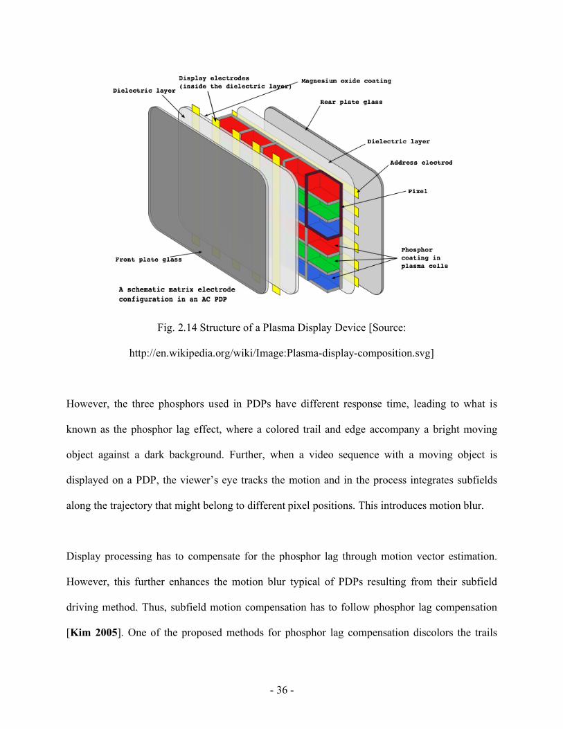
2.3.1.2 Plasma Display Panel (PDP)
PDP displays consist of small cells filled with neon or xenon gas and contained within a chamber
with a front and a rear glass plate (Figure 2.14). Strong voltage is applied across the electrodes
positioned between the glass plates, causing the gas to ionize and discharge ultraviolet rays. The
ionized state during gas discharge is called plasma. In the color panels, the back of each cell is
coated with red, green or blue phosphors. When ultraviolet rays hit the phosphors, photons with
corresponding wavelengths are emitted, which we see as colored light.
PDP displays can have large size and thin width, higher brightness (1000 lux or more) with
contrast ratio as high as 30,000:1, and greater viewing angle than many other competing
technologies. The displays have wide color gamuts.
- 36 -
Fig. 2.14 Structure of a Plasma Display Device [Source:
http://en.wikipedia.org/wiki/Image:Plasma-display-composition.svg]
However, the three phosphors used in PDPs have different response time, leading to what is
known as the phosphor lag effect, where a colored trail and edge accompany a bright moving
object against a dark background. Further, when a video sequence with a moving object is
displayed on a PDP, the viewer’s eye tracks the motion and in the process integrates subfields
along the trajectory that might belong to different pixel positions. This introduces motion blur.
Display processing has to compensate for the phosphor lag through motion vector estimation.
However, this further enhances the motion blur typical of PDPs resulting from their subfield
driving method. Thus, subfield motion compensation has to follow phosphor lag compensation
[Kim 2005]. One of the proposed methods for phosphor lag compensation discolors the trails

- 37 -
and edges of moving objects and converts their colors into gray. This helps reduce the color
artifact since human eye is less sensitive to variations in gray than variations in chromatic colors
[Oh 2006].
2.3.1.3 Digital Light Projector (DLP™)
The core of the DLP™ projection system is an optical semiconductor called Digital Micromirror
Device, or DMD, invented by Larry Hornbeck of Texas Instruments in 1987 [DLP 2008]. The
DMD is a highly sophisticated light switch capable of modulating light with high precision. Over
two million hinge-mounted microscopic mirrors arranged in a rectangular array are housed in the
DMD chip. A digital signal activates a tiny electrode beneath each mirror, causing that mirror to
tilt toward (ON) or away (OFF) from the light source. When the DMD is coordinated with digital
video, a light source and a projection lens, a grayscale digital image can be reflected onto a
screen or other surfaces, as shown in Figure 2.15, by creating a light or dark pixel through light
modulation using pulse width modulation technique (PWM). The mirrors can be switched on and
off several thousand times per second, allowing the display of bit-streamed video. The use of
PWM techniques results in a linear device transfer function from input signal to light output
[Pettitt 2001].
To display color, the light from the projection system is passed through a color wheel fitted with
red, green and blue filters, shown in Figure 2.16. Colors are shown in sequence on to the surface
of the DLP™ chip. The switching of a given mirror and the duration of its on or off time are
determined based on what color the mirror is supposed to project. As an example, to generate a
yellow pixel, a mirror alternately flashes red and green colors with high frequency such that a

- 38 -
temporal integration takes place in observer’s eye, creating a sensation of yellow hue. A single-
chip DLP™ projection system, used in televisions, home theater systems and business
projectors, can produce 16.7 million colors.
Fig. 2.15 Optical switching through DMD [Source: Pettitt 2001, Fig. 2]
Fig. 2.16 Schematic of a DLP system [Source: DLP 2008]

- 39 -
2.3.1.4 Organic Light Emitting Diode (OLED) Displays
OLED is a form of light-emitting diode composed of phosphoric or fluorescent organic thin film
(Figure 2.17). OLED structure consists of an emissive layer, a conductive layer, a substrate and
the electrodes. The layers are made of organic materials with variable conduction. The
electroluminescent emission is caused by electric voltage applied across the electrodes, which
results in light of different colors.
Fig. 2.17 Structure of an OLED device [Source:
http://www.samsungsdi.com/contents/en/tech/disClass_03_01.html]
OLED displays consume significantly low power and can be brighter and considerably thinner
than LCDs. They do not require backlighting either. However, the organic materials deteriorate
over time, which reduces the lifetime for these displays.

- 40 -
2.3.1.5 Laser Displays
Laser TV is an HDTV with solid state lasers providing three primary colors, red, green and blue.
In a recent development, a display based on laser light sources was reported to achieve a very
high luminance (500 cd/m2) and significantly wider color gamut, namely 190% of the gamut
defined by Rec. 709 [Sugiura 2007]. Figure 2.18 compares the color gamut of this display with
that of Rec. 709 and an LED backlit LCD (discussed later in this chapter). Note that the
primaries in the laser TV are almost monochromatic. The display developed by Sugiura et al
eliminated color wheel typically used in the projection display to achieve field sequential color,
and instead directly controlled the illumination timing of the three-primary color laser beams.
Fig. 2.18 Color gamut of laser projection TV in comparison with that of Rec. 709 and LED
backlit LCD [Source: Sugiura 2007, Fig.3]
An additional feature of this display, and possibly of other laser displays, is its compliance with
xvYCC, an extended color space for moving pictures proposed by International Electrotechnical
Commission (IEC 61966-2-4) [Sugiura 2007]. Figure 2.19 shows the extended region available

- 41 -
in xvYCC color space. This color space allows red, green and blue pixel values to go below 0
(darker colors) and above 1 (very bright colors).
Fig. 2.19 Extended region in xvYCC color space [Source: Sugiura 2007, Fig.2]
2.3.1.6 Field Emission Displays (FED)
A field emission display or FED is one of the most recent developments among the display
technologies. An FED is a type of flat panel display that employs field-emitting cathodes
coupled with phosphor coatings to generate light. An FED is similar to a CRT in operation, but is
much thinner as it does not require an electron gun. Instead, it contains a large emitter array,
which, loosely speaking, is placed closely behind a phosphor layer that emits light when
subjected to field emission. Figure 2.20 shows the structure of a Spindt-type color FED, recently
developed by Itoh et al [Itoh 2007]. The focus electrode layer is designed to reduce color
crosstalk. The total thickness of the panel is only 2.8 mm. FEDs are low power consuming
devices particularly suited for high-quality motion pictures because of their quick response.

- 42 -
Fig. 2.20 Structure of a Spindt-type color FED [Source: Itoh 2007, Fig.3]
2.3.2 Color Processing in Wide Gamut and Multi-Primary Displays
Displays having larger gamuts than the gamut of a conventional display with standard primaries
are termed as wide gamut (WG) displays. In one of the earliest publication on HDTV
colorimetry, DeMarsh [DeMarsh 1991] referred to wide gamut primaries as those primaries that
are capable of displaying a larger gamut than the SMPTE “C” primaries (defined in SMPTE RP-
145 standard). However, there is no specific set of primaries termed as wide gamut primaries
[Kwak 2005]. It is reasonable to make such determination based on contemporary ITU-R BT
Rec. 709 primaries defined for HDTV. However, it is a common practice to represent gamuts of
modern displays in terms of percent of NTSC color gamut, which is still an industry benchmark.
Multi-primary displays (MPD) are those that have more than three primary colors. These are
essentially wide gamut displays as they can produce more natural colors than the conventional
displays can, particularly in the cyan and yellow regions in the color space. These displays
generate multi-primary signals from the incoming three standard primary signals. Note that a

- 43 -
wide gamut display does not necessarily have to be multi-primary, examples being 3-primary
LCD with LED backlight and RGB laser displays.
Among the problems associated with color processing in an MPD are those of an over-
determined system with multiple gamut mapping solutions to convert 3-primary inputs to multi-
primary outputs, and of metamerism, a many-to-one mapping of colors that may result in
discontinuities. Solutions to these problems have been suggested with 5-primary DLP™
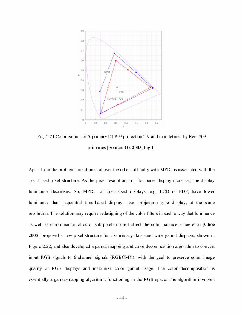
projection television developed by Samsung [Ok 2005]. The display has yellow and cyan
primaries, in addition to red, green and blue. Figure 2.21 compares the color gamut of this
display to that defined by Rec. 709 primaries. Decomposition of five primaries into two color
components was proposed, one consisting of three primaries and one consisting of two primaries.
Two arbitrary color components from the five primaries were selected and their values at the
gamut boundary were used to construct an LUT. The remaining three components were
calculated using inverse matrix. The paper also suggested a method for gamut mapping so that
natural images conforming to Rec. 709 can be displayed on 5-primary display without causing
over-saturation or under-saturation of chroma in high lightness or low lightness regions. This
involved lightness mapping of the gamut vertices (or cusps), followed by a chroma mapping.
- 44 -
Fig. 2.21 Color gamuts of 5-primary DLP™ projection TV and that defined by Rec. 709
primaries [Source: Ok 2005, Fig.1]
Apart from the problems mentioned above, the other difficulty with MPDs is associated with the
area-based pixel structure. As the pixel resolution in a flat panel display increases, the display
luminance decreases. So, MPDs for area-based displays, e.g. LCD or PDP, have lower
luminance than sequential time-based displays, e.g. projection type display, at the same
resolution. The solution may require redesigning of the color filters in such a way that luminance
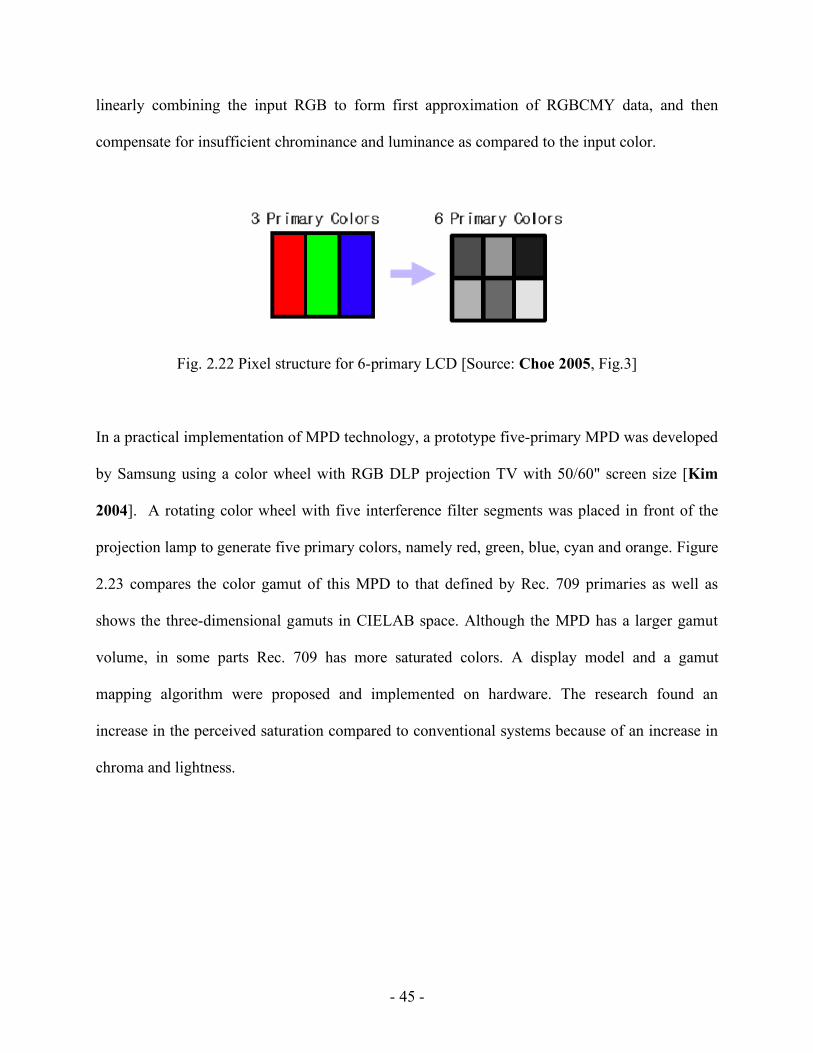
as well as chrominance ratios of sub-pixels do not affect the color balance. Choe et al [Choe
2005] proposed a new pixel structure for six-primary flat-panel wide gamut displays, shown in
Figure 2.22, and also developed a gamut mapping and color decomposition algorithm to convert
input RGB signals to 6-channel signals (RGBCMY), with the goal to preserve color image
quality of RGB displays and maximize color gamut usage. The color decomposition is
essentially a gamut-mapping algorithm, functioning in the RGB space. The algorithm involved
- 45 -
linearly combining the input RGB to form first approximation of RGBCMY data, and then
compensate for insufficient chrominance and luminance as compared to the input color.
Fig. 2.22 Pixel structure for 6-primary LCD [Source: Choe 2005, Fig.3]
In a practical implementation of MPD technology, a prototype five-primary MPD was developed
by Samsung using a color wheel with RGB DLP projection TV with 50/60" screen size [Kim
2004]. A rotating color wheel with five interference filter segments was placed in front of the
projection lamp to generate five primary colors, namely red, green, blue, cyan and orange. Figure
2.23 compares the color gamut of this MPD to that defined by Rec. 709 primaries as well as
shows the three-dimensional gamuts in CIELAB space. Although the MPD has a larger gamut
volume, in some parts Rec. 709 has more saturated colors. A display model and a gamut
mapping algorithm were proposed and implemented on hardware. The research found an
increase in the perceived saturation compared to conventional systems because of an increase in
chroma and lightness.

- 46 -
Fig. 2.23 Comparison of color gamuts of the five-primary MPD and Rec. 709 in u’-v’ diagram
and in CIELAB space [Source: Kim 2004, Fig. 2]
Multi-primary technology has also been applied to develop wide gamut high efficiency LCD
panels with four (RGBY) and five (RGBCY) primaries coupled with Cold Cathode Fluorescent
Lamp (CCFL) backlight [Roth 2007]. The backlight and color filter properties play an important
role in determining the color and intensities of the individual primaries of such displays. The
four-primary display was equipped with normal color gamut CCFL backlight, while the five-
primary had wide gamut CCFL backlight. Identical sub-pixel sizes were used for manufacturing
convenience. An optimization of the color filters and fine-tuning of the phosphor mixture in the
backlight helped achieve an appropriate white point. Like many other MPDs, these displays have
yellow and cyan filters aimed at increasing the color gamut area coverage in terms of % NTSC,
increasing the white point luminance and getting a good color coverage and color intensity
distribution. A multi-primary scaling algorithm was proposed that allowed the use of same TFT
backpanel and driver electronics as in regular RGB panels. The color filters were applied to the
original sub-pixels, increasing the effective pixel size. However, the perceived resolution was not
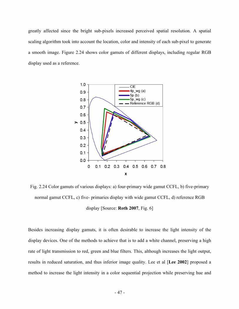
- 47 -
greatly affected since the bright sub-pixels increased perceived spatial resolution. A spatial
scaling algorithm took into account the location, color and intensity of each sub-pixel to generate
a smooth image. Figure 2.24 shows color gamuts of different displays, including regular RGB
display used as a reference.
Fig. 2.24 Color gamuts of various displays: a) four-primary wide gamut CCFL, b) five-primary
normal gamut CCFL, c) five- primaries display with wide gamut CCFL, d) reference RGB
display [Source: Roth 2007, Fig. 6]
Besides increasing display gamuts, it is often desirable to increase the light intensity of the
display devices. One of the methods to achieve that is to add a white channel, preserving a high
rate of light transmission to red, green and blue filters. This, although increases the light output,
results in reduced saturation, and thus inferior image quality. Lee et al [Lee 2002] proposed a
method to increase the light intensity in a color sequential projection while preserving hue and

- 48 -
saturation of the original RGB input color. Figure 2.25 shows the concept. If Tr, Tg, Tb and Tw
are filter transmittances and Er, Eg, Eb and Ew are exposure times per frame for the four filters,
the output light intensity Yout corresponding to an input light intensity Yin is given by:
!
Yout = Yin *(TrEr +TgEg +TbEb +TwEw ) (2.1)
Fig. 2.25 Single panel display with four color filters a) schema, b) timing diagram [Source: Lee
2002, Fig. 1]
Figure 2.26 demonstrates the problem associated with adding a fourth channel in 3-color vector
space. Adding a color C2 to the input color C1 leads to color C3 that has a different hue (given by
angle) and saturation. Note that C2 has the same amount of red, green and blue, resulting in a
white of given lightness. A compensation vector C4 is needed to change the direction of output
color vector to the direction of original input color vector. However, since RGB is not a

- 49 -
perceptually linear space, the compensation vector is not sufficient to preserve hue and saturation
of the input color. In the proposed method for RGB to RGBW conversion, RGBW color space
was divided into constant scaling space and gamut scaling space, so that different scaling could
be applied as appropriate. The transformation involved three steps, namely, determination of
scale space, scaling the input signal and finally, separation of RGB and white signal.
Fig. 2.26 Vector representation of RGBW processing [Source: Lee 2002, Fig. 3]
It seems more appropriate to use an opponent color space like CIELAB for this computation, but
a solution in the RGB space was probably preferred due to the implementation issues.
Displays using RGBW primaries can achieve higher luminance, and often an improved
efficiency through lower power consumption. Displays such as LCD and DMD typically employ
a spatial light modulator to add an amount of luminance from the white primary that is correlated
with the amount of input RGB. They typically resort to a tradeoff of color reproduction for
higher efficiency, resulting in less saturated and/or less bright colors in certain cases. Emissive
- 50 -
displays like OLED uses an array of light-emitting subpixels as described before, thus the
efficiency of the display is determined by the efficiency of the subpixels. A filtered white RGBW
(W-RGBW) OLED is a multi-primary display that uses an independently controlled white
emitter for each subpixel. RGB subpixels are provided with color filters while white subpixels
have none and thus, are more efficient than the color subpixels. Murdoch et al [Murdoch 2006]
presented a color-processing algorithm that exploited this feature in W-RGBW OLED displays
to accomplish color accuracy and power savings at the same time. The method involved
transferring the neutral luminance, given by the minimum of RGB digital counts or a fraction of
it, from less efficient RGB subpixels to more efficient white subpixel to generate a metameric
color with high colorimetric accuracy. If the white primary has the same chromaticities as the
display primaries, RGB subpixel values can be used directly to form RGBW signal. However,
the white replacement algorithm may introduce color reproduction error if broadband source
used in the display does not correspond to the intended display white point. In such cases, RGB
chromaticities must first be transformed to white normalized RGB, or RnGnBn, such that the
equal RnGnBn triad produces the same chromaticity coordinates as the white primary. Then in
RnGnBn space, a certain fraction (white mixing ratio) of the minimum of RGB is subtracted from
RnGnBn, and the subtracted result is then normalized to return to the white-point normalized
RGB space. Note that filtered white RGBW OLED displays use white to efficiently replace
neutral luminance, while RGBW displays with additional white channel use white to augment
luminance. The efficiency of W-RGBW OLED displays depends largely on how often the white
subpixel is used to replace RGB subpixels, and thus on the picture content.
- 51 -
As mentioned before, using multi-primaries is not the only way to achieve wider gamuts.
Recently, a prototype of a high resolution (WUXGA: 1920x1200) LCD with LED backlights has
been developed, offering a wide color gamut and high luminance [Sugiura 2006]. In LED
backlit displays, RGB color LEDs are used as point sources for backlighting, with white color
being produced by mixing the three colors using an optical waveguide. However, several
problems are encountered in this technology. The white point chromaticities shift over time due
to the changes in the wavelength of the emitted beam as well as the light output of the LEDs.
Color variation across the display can be observed as the uniformity in the luminance output of
the LEDs deteriorates over time. Sugiura et al’s prototype incorporated a feedback control circuit
with optical sensor for the stabilization of luminance and chromaticity of the backlight, a color
non-uniformity correction circuit as well as a gamma correction function.
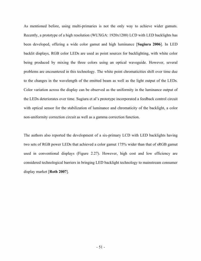
The authors also reported the development of a six-primary LCD with LED backlights having
two sets of RGB power LEDs that achieved a color gamut 175% wider than that of sRGB gamut
used in conventional displays (Figure 2.27). However, high cost and low efficiency are
considered technological barriers in bringing LED backlight technology to mainstream consumer
display market [Roth 2007].
- 52 -
Fig. 2.27 Color gamut of six-primary LCD with LED backlight [Source: Sugiura 2006, Fig. 13]
2.4 Challenges and Opportunities in Color Video Processing
In the world of consumer video, research and development activities are expected to continue
both in the realms of display-dependent processing and display-independent processing, with
overlapping activities being a likely scenario. Many of the ongoing development efforts in the
display industry focus on flat-panel displays. While we are not likely to see much increase in the
display resolution from where we already are, there are several technical challenges posed by
modern displays that remain to be addressed. For example, the solution to the problem of loss of
perceived resolution with increasing object speed on many contemporary flat-panel displays
needs motion compensated picture rate conversion as well as high-speed cameras and
transmission [de Haan 2007]. Many of the emerging display technologies suffer from various
temporal artifacts, which must be remedied at the hardware and/or software level [de Haan
2001]. While advanced display technologies like wide gamut, multi-primary displays pave the
path for widespread adoption of HDTV standard and systems, one of the challenges will be to

- 53 -
optimally show legacy video with standard-definition color content on modern displays,
requiring advanced resolution up-conversion [de Haan 2007]. In addition to the display
technologies discussed in this chapter, there are other ambitious emerging technologies like high
dynamic range display, 3D display and fine grey-scale quantization display (10bitTV) that can
open new frontiers for color video processing.
As we look into the state-of-the-art of color video processing, it is worthwhile for us to step back
and take an objective view from the perspective of color science. To this end, Fairchild presented
a critical review of some of the color processing in a typical video processing chain [Fairchild
2007]. One of the key aspects of color processing in consumer video applications is that it is
essentially display-centric. Capture-end of a typical video system workflow does not involve a
colorimetrically accurate method, resulting in color information about the original scene being
discarded at the outset of video processing. Color processing for video attempts to achieve high
picture quality for a standard display, which may or may not be desirable in a given application
context.
As outlined in this chapter, several steps in the video processing chain that are not directly
related to color can affect the picture as well as color quality. Nevertheless, these steps do not
appropriately address the color issues. For example, a nonlinear gamma correction followed by a
subsampling of color difference signals in the encoding stage results in luminance and
chrominance errors during any differential processing of luminance and chrominance data, which
are ignored in video processing. Further, video processing typically avoids using a perceptual
space in which luminance and chrominance channel data are orthogonal for practical purposes. A

- 54 -
color space like YCBCR introduces crosstalk between these channels leading to color error at the
display end. Video processing algorithms do not take into account the viewing conditions as is
done in color and image appearance modeling. These problems are handled on an ad hoc basis
by the end-user to achieve a pleasing picture quality for a given display. The solution is far from
desirable from accurate color reproduction perspective.
Several practical improvements in television video processing can help achieve superior color
reproduction [Fairchild 2007]. Using characterized video cameras with recorded camera settings
and video information will provide an option to retrieve colorimetric information of the scene.
Video processing in a perceptually linear space can help reduce artifacts and produce better color
quality. At the output end of the processing chain, displays with proper colorimetric
characterization will ensure consistent color reproduction across different display technologies.
Integrating color appearance issues into the video processing algorithms will make a display
responsive to changes in the ambient viewing conditions.
As the capabilities of today’s display technologies keep advancing at a remarkable pace,
consumer demand for superior picture quality is stronger than ever before. Color plays a vital
role in determining the quality of a display, and any future development efforts in color video
processing must recognize the potential for improvement in color reproduction capabilities of
various emerging display technologies. Video researchers and color scientists must work
together to transform this potential into reality.
Related Documents