1 Ch 8 LAN Technologies and Network Topology

Ch 8 LAN Technologies and Network Topology
Jan 02, 2016
Ch 8 LAN Technologies and Network Topology. Scope. Describes the concepts underlying local network technologies Describes basic network topology Examines examples of popular local network technologies. Classification Terminology. Network technologies classified into three broad categories - PowerPoint PPT Presentation
Welcome message from author
This document is posted to help you gain knowledge. Please leave a comment to let me know what you think about it! Share it to your friends and learn new things together.
Transcript

1
Ch 8 LAN Technologies and Network Topology

2
ScopeScope
Describes the concepts underlying local network technologies
Describes basic network topologyExamines examples of popular local network
technologies

3
Classification TerminologyClassification Terminology
Network technologies classified into three broad categories Local Area Network (LAN) Metropolitan Area Network (MAN) Wide Area Network (WAN)
LAN and WAN most widely deployed

4
Scientific Justification for LANs
Scientific Justification for LANs
A computer is more likely to communicate with computers that are nearby than with computers that are distant
A computer is more likely to communicate with the same set of computers repeatedly
Known as the locality principles

5
LANsLANsMany LAN technologies exist
Designed for sharing (needs medium access control, MAC)
IEEE 802.3, 802.4, 802.5, 802.11Key features of a LAN
High throughputRelatively low costLimited to short distanceOften rely on shared media rather than direct
connections (or said point-to-point connections)

6
Network TopologiesNetwork TopologiesSpecifies general “shape” of a network
Star Ring Bus
Each topology has advantages and disadvantages

7
Star TopologyStar Topology
Central point of network known as hubEach computer has separate connection to
hub

8
Ring TopologyRing Topology
To be connected in a closed loopConnections go directly from one computer
to anotherNo central facility

9
Bus TopologyBus Topology
Shared medium forms main interconnectBroadcasting orientedOnly one computer sends a signal at any time
10
Example Bus Network: Ethernet
Example Bus Network: Ethernet
Most popular LANsIEEE standard 802.3Several generations
Same frame format Different data rates (10/100/1000 Mbps) Different wiring schemes (e.g., 10Base2,
10BaseT)

11
Manchester EncodingManchester Encoding
Hardware can detect a change in voltage easily than a fixed value Use rising and falling edges to encode data 1 and 0 One slot for a bit Voltage change occur exactly half-way through a slot
12
Manchester EncodingManchester EncodingA preamble is used to have the receiver know when
each time slot begins The preamble consists of 64 alternating 1’s and 0’s
sent before the frame

13
Sharing on an EthernetSharing on an Ethernet
Signal propagates across entire cable (terminator located at both ends)
All stations receive transmission (only the dest. can accept the frame)
Only one station transmits at any timeCSMA/CD media access scheme

14
CSMA/CD ParadigmCSMA/CD Paradigm
Multiple Access (MA)Multiple computers attach to shared mediaEach uses same access algorithm
Carrier Sense (CS)Wait until medium idleBegin to transmit frame

15
Two simultaneous transmissionsInterfere with one anotherCalled collision
CSMA plus Collision Detection (CD)Listen to medium during transmissionDetect whether another station’s signal interferesBack off from interference and try again
CSMA/CD ParadigmCSMA/CD Paradigm

16
Backoff After CollisionBackoff After Collision
When collision occursWait random time t, 0 ≤ t ≤ d (tome slot)Use CSMA and try again
Double range for each successive collisionCalled exponential backoff

17
Wireless LANWireless LAN IEEE 802.11
switch
AP
LAN
DHCP
server
Cat 5
Cat 5

18
Wireless LANWireless LANWireless ADSL
line
ADDSL router
Cat 5
straight
line
ADDSL router
Private
IP
4-in-1 頻寬分享器
(NAT, DHCP and Hub)
Cat 5
CO
CO

19
Wireless LANWireless LANWireless ADSL
line
ADDSL router
Cat 5
AP
Cat 5
4-in-1 頻寬分享器
(NAT, DHCP and Hub)
CO

20
Limited range (hidden terminal problem)Not all stations receive all transmissionsCannot use CSMA/CDE.g., STA2 can detect the collision
CSMA/CACSMA/CA
STA1 STA2 STA3
21
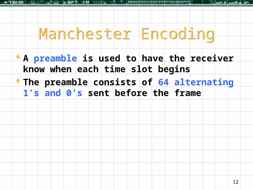
CSMA/CACSMA/CAPurpose: inform all stations in range of X or Y
before transmissionKnown as Collision Avoidance (CA)
STA1STA2 STA3
RTS
CTS
Area cleared by RTS (Request To Send)
Area cleared by CTS (Clear To Send)

22
Source Destination
ACK
Data
CTS
RTS
CSMA/CACSMA/CA4-way MAC frame exchange protocol

23
Token Passing Ring Transmission
Token Passing Ring Transmission
Station waits for token before sendingSignal travels around entire ringSender receives its own transmission

24
Token PassingToken PassingToken
Special, reserved message Small bit pattern differs from normal data frames
Station Waits for the token to arrive Transmits one packet around ring Transmits token around ring
When no station has data to send Token circulates continuously
Guarantees fair access

25
Strengths of Token Ring Approach
Strengths of Token Ring Approach
Easy detection of broken ring interference (by the sender) hardware failures (passing mode)
No collision

26
Weaknesses of Token Ring Approach
Weaknesses of Token Ring Approach
Broken wire disables entire ringPoint-to-point wiring
Awkward in office environment Difficult to add / move stations

27
Token Passing Ring Technologies
Token Passing Ring Technologies
LocalTalk Operated at 10 Mbps (CSMA/CA)
IBM Token Ring Originally operated at 4 Mbps Later version operated at 16 Mbps
FDDI (Fiber Distributed Data Interconnect ) Operated at 100 Mbps

28
FDDI Failure RecoveryFDDI Failure Recovery
Uses two fiber ringsAutomatic failure recovery
Dual-attachedCounter rotating (data travels in the reverse
direction across the second ring)Self healing (the process of reconfiguring to
avoid failure)

29
Illustration of FDDIFailure Recovery
Illustration of FDDIFailure Recovery

30
FDDI TerminologyFDDI Terminology FDDI
Uses optical fibers High reliability Immune to interference
CDDI FDDI over copper Same frame format Same data rate Less noise immunity

31
FDDI Hub TechnologyFDDI Hub Technology
Part of FDDI standardStations attach to hubSame frame format and data rate as FDDICalled star-shaped ringAdvantages
WiringReliability

32
The End

33
Example Star Network: ATM
Example Star Network: ATM
Asynchronous Transfer Mode (ATM)Designed by telephone companiesIntended to accommodate
VoiceVideoData

34
Building block known as ATM switchEach station connects to switch (star topology)Switches can be interconnectedOnly propagate data to the communicating pair
Example Star Network: ATM
Example Star Network: ATM

35
Details of ATM ConnectionDetails of ATM Connection
Full-duplex connectionsTwo fibers requiredOperates at 155 Mbps or faster

36
ATM CharacteristicsATM Characteristics
High data rates (e.g. 155 Mbps)Fixed size packets
Called cellsImportant for voice
Cell size is 53 octets48 octets of data5 octets of header
Related Documents