Ch 3 Analysis and Transmission of Signals ENGR 4323/5323 igital and Analog Communication Engineering and Physics University of Central Oklahoma Dr. Mohamed Bingabr

Ch 3 Analysis and Transmission of Signals ENGR 4323/5323 Digital and Analog Communication Engineering and Physics University of Central Oklahoma Dr. Mohamed.
Dec 14, 2015
Welcome message from author
This document is posted to help you gain knowledge. Please leave a comment to let me know what you think about it! Share it to your friends and learn new things together.
Transcript

Ch 3Analysis and Transmission of Signals
ENGR 4323/5323Digital and Analog Communication
Engineering and PhysicsUniversity of Central Oklahoma
Dr. Mohamed Bingabr

Chapter Outline
• Aperiodic Signal Representation by Fourier Integral• Fourier Transform of Useful Functions• Properties of Fourier Transform• Signal Transmission Through LTIC Systems• Ideal and Practical Filters• Signal Distortion over a Communication Channel• Signal Energy and Energy Spectral Density• Signal Power and Power Spectral Density

The Fourier Transform Spectrum
The Fourier transform integrals:
)()()(
)()(
X
tj
eXX
dtetxX
Fourier transform (FT) allows us to represent aperiodic (not periodic) signal in term of its frequency ω.
ω
|X(ω)|
x(t)

The Fourier Transform Spectrum
The Inverse Fourier transform:
deXtx tj)(2
1)(
)()()( XeXX
The Amplitude (Magnitude) Spectrum
The Phase Spectrum
The amplitude spectrum is an even function and the phase is an odd function.

Useful Functions
Unit Gate Function
2/|| 1
2/|| 5.0
2/|| 0
t
t
tt
rect
Unit Triangle Function
2/|| /21
2/|| 0
tt
tt
/2-/2
/2-/2
1
1
t
t

Useful Functions
Interpolation Function
0for t 1)(sinc
for t 0)(sinc
sin)(sinc
t
ktt
tt
sinc(t)
t

Example
Find the FT, the magnitude, and the phase spectrum of x(t) = rect(t/).
Answer
)2/sinc()/()(2/
2/
dtetrectX tj
The spectrum of a pulse extend from 0 to . However, much of the spectrum is concentrated within the first lobe (=0 to 2/)
What is the bandwidth of the above pulse?

Examples
Find the FT of the unit impulse (t).Answer
1)()(
dtetX tj
Find the inverse FT of ().Answer
)(21
impulsean isconstant a of spectrum theso
2
1)(
2
1)(
detx tj

Examples
Find the FT of the unit impulse train Answer
)(0
tT
n
n
n
n
tjnT
nT
X
eT
t
)(2
)(
1)(
00
0
0
0


Properties of the Fourier Transform• Linearity:
• Let and
then
Xtx Yty
YXtytx
• Time Scaling:
• Let
then
Xtx
aX
aatx
1
Compression in the time domain results in expansion in the frequency domain
Internet channel A can transmit 100k pulse/sec and channel B can transmit 200k pulse/sec. Which channel does require higher bandwidth?

Properties of the Fourier Transform
• Time Reversal:
• Let
then ( ) ( )x t X
Xtx
• Left or Right Shift in Time:
• Let
then
Xtx
00
tjeXttx
Time shift effects the phase and not the magnitude.

Properties of the Fourier Transform• Multiplication by a Complex Exponential (Freq. Shift
Property):
• Let
then 00( ) ( )j tx t e X
Xtx
• Multiplication by a Sinusoid (Amplitude Modulation):
Let
then
Xtx
000 2
1cos XXttx
cos0t is the carrier, x(t) is the modulating signal (message),x(t) cos0t is the modulated signal.

Example: Amplitude Modulation
Example: Find the FT for the signal x(t)
ttrecttx 10cos)4/()( -2 2
A

Amplitude Modulation
ttmt cAM cos)()( Modulation
]2cos1)[(5.0 cos)( 2 ttmtt ccAM
Demodulation
Then lowpass filtering

Properties of the Fourier Transform
• Differentiation in the Time Domain:
Let
then ( ) ( ) ( )n
nn
dx t j X
dt
Xtx
• Differentiation in the Frequency Domain:
• Let
then ( ) ( ) ( )n
n nn
dt x t j X
d
Xtx
Example: Use the time-differentiation property to find the Fourier Transform of the triangle pulse x(t) = (t/)

Properties of the Fourier Transform• Integration in the Time Domain:
Let
Then1
( ) ( ) (0) ( )t
x d X Xj
Xtx
• Convolution and Multiplication in the Time Domain:
Let
Then ( ) ( ) ( ) ( )x t y t X Y
Yty
Xtx
)()(2
1)()( 2121
XXtxtx Frequency convolution

Example
Find the system response to the input x(t) = e-at u(t) if the system impulse response is h(t) = e-bt u(t).
Properties of the Fourier Transform
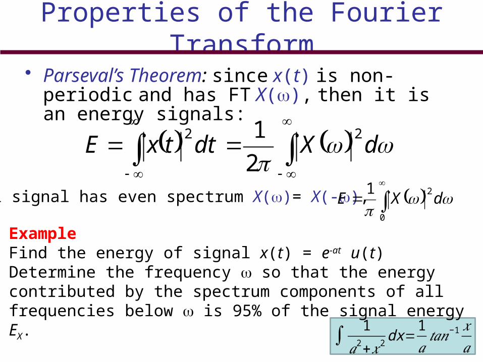
• Parseval’s Theorem: since x(t) is non-periodic and has FT X(), then it is an energy signals:
dXdttxE22
2
1
Real signal has even spectrum X()= X(-),
0
21
dXE
ExampleFind the energy of signal x(t) = e-at u(t) Determine the frequency so that the energy contributed by the spectrum components of all frequencies below is 95% of the signal energy EX.
Answer: = 12.7a rad/sec 1
𝑎2+𝑥2 dx=1𝑎𝑡𝑎𝑛−1 𝑥
𝑎

Properties of the Fourier Transform• Duality ( Similarity) :
• Let
then ( ) 2 ( )X t x
Xtx


Signal Transmission Through a Linear System

Distortionless Transmission (System)
Slope is constant for distortionless system

Example 3.16
A transmission medium is modeled by a simple RC low-pass filter shown below. If g(t) and y(t) are the input and the output, respectively to the circuit, determine the transfer function H(f), θh(f), and td(f). For distortionless transmission through this filter, what is the requirement on the bandwidth of g(t) if amplitude response variation within 2% and time delay variation within 5% are tolerable? What is the transmission delay? Find the output y(t).
𝑑𝑑𝑥
( 𝑡𝑎𝑛−1𝑎𝑥 )= 𝑎1+𝑎2𝑥2
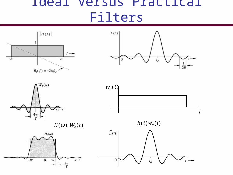
Ideal Versus Practical Filters
t
wR(t)
h(t)wR(t)H(ω)*WR(t)

Ideal Versus Practical Filters

Signal Distortion Over a Communication Channel
1. Linear Distortion
2. Channel Nonlinearities
3. Multipath Effects
4. Fading Channels
- Channel fading vary with time. To overcome this distortion is to use automatic gain control (AGC)

Linear DistortionChannel causes magnitude distortion, phase distortion, or both.
Example: A channel is modeled by a low-pass filter with transfer function H(f) give by
𝐻 ( 𝑓 )={(1+𝑘𝑐𝑜𝑠2𝜋 𝑓𝑇 )𝑒− 𝑗2𝜋 𝑓 𝑡 𝑑❑
|𝑓 |<𝐵0|𝑓 |>𝐵
A pulse g(t) band-limited to B Hz is applied at the input of this filter. Find the output y(t).

Nonlinear Distortion
y(t) = f(g(t)) f(g) can be expanded by Maclaurin series
If the bandwidth of g(t) is B Hz then the bandwidth of y(t) is kB Hz.
y (𝑡 )=𝑎0+𝑎1𝑔 (𝑡 )+𝑎2𝑔2 (𝑡 )+…+𝑎𝑘𝑔
𝑘 (𝑡 )
Example: The input x(t) and the output y(t) of a certain nonlinear channel are related as
y(t) = x(t) + 0.000158 x2(t)Find the output signal y(t) and its spectrum Y(f) if the input signal is x(t) = 2000 sinc(2000t). Verify that the bandwidth of the output signal is twice that of the input signal. This is the result of signal squaring. Can the signal x(t) be recovered (without distortion) from the output y(t)?

Continue Example

Distortion Caused by Multipath Effects
𝐻 ( 𝑓 )=𝑒− 𝑗2 𝜋 𝑓 𝑡 𝑑+α 𝑒− 𝑗2 𝜋 𝑓 (𝑡¿¿𝑑+∆ 𝑡 )¿
𝐻 ( 𝑓 )=𝑒− 𝑗2 𝜋 𝑓 𝑡 𝑑(1+α𝑐𝑜𝑠2𝜋 𝑓 ∆ 𝑡− 𝑗 α 𝑠𝑖𝑛 2𝜋 𝑓 ∆ 𝑡)
𝐻 ( 𝑓 )=√1+α 2+2α𝑐𝑜𝑠2𝜋 𝑓 ∆ 𝑡 𝑒𝑥𝑝 [− 𝑗 (2𝜋 𝑓 𝑡𝑑+𝑡𝑎𝑛− 1 α 𝑠𝑖𝑛2𝜋 𝑓 ∆𝑡
1+α 𝑐𝑜𝑠2𝜋 𝑓 ∆𝑡 )]
𝐻 ( 𝑓 )=𝑒− 𝑗2 𝜋 𝑓 𝑡 𝑑(1+α𝑒− 𝑗 2𝜋 𝑓 ∆𝑡)
Common distortion in this type of channel is frequency selective fading

Energy and Energy Spectral Density
𝐸𝑔=− ∞
∞
𝑔 (𝑡 )𝑔∗ (𝑡 )𝑑𝑡
𝐸𝑔=− ∞
∞
|𝐺( 𝑓 )|2𝑑𝑓
Energy in the time domain
Energy in the frequency domain
Ψ𝑔 ( 𝑓 )=|𝐺( 𝑓 )|2
Energy spectral density (ESD), , is the energy per unit bandwidth (in hertz) of the spectral components of g(t) centered at frequency f.
Ψ 𝑦( 𝑓 )=|𝐻 ( 𝑓 )|2Ψ 𝑥( 𝑓 )
The ESD of the system’s output in term of the input ESD is
𝐻 ( 𝑓 )Ψ 𝑥 ( 𝑓 )

Essential Bandwidth of a Signal
Estimate the essential bandwidth of a rectangular pulse g(t) = (t/T), where the essential bandwidth must contain at least 90% of the pulse energy.
𝐸𝑔=− ∞
∞
𝑔2 (𝑡 )𝑑𝑡= −𝑇 /2
𝑇 /2
𝑑𝑡=𝑇
𝐸𝐵=−𝐵
𝐵
𝑇 2𝑠𝑖𝑛𝑐2 (𝜋 𝑓𝑇 ) 𝑑𝑓=0.9𝑇
B = 1/T Hz

Energy of Modulated Signals
The modulated signal appears more energetic than the signal g(t) but its energy is half of the energy of the signal g(t). Why?
𝜑 (𝑡 )=𝑔 (𝑡 )𝑐𝑜𝑠2𝜋 𝑓 0 𝑡
Φ ( 𝑓 )=12 [𝐺 ( 𝑓 + 𝑓 0 )+𝐺( 𝑓 − 𝑓 0) ]
Ψ𝜑 ( 𝑓 )=14 |𝐺 ( 𝑓 + 𝑓 0 )+𝐺( 𝑓 − 𝑓 0)|
2
Ψ𝜑 ( 𝑓 )=14
Ψ𝑔 ( 𝑓 + 𝑓 0 )+14
Ψ𝑔
( 𝑓 + 𝑓 0)
𝐸𝜑=12𝐸𝑔
If f0 > 2B then

Time Autocorrelation Function and Energy Spectral Density
The autocorrelation of a signal g(t) and its ESD form a Fourier transform pair, that is
Ψ𝑔 ( 𝑓 )𝜓𝑔(𝜏 )
Example: Find the time autocorrelation function of the signal g(t) = e-atu(t), and from it determine the ESD of g(t).

Signal Power and Power Spectral Density
Power Pg of the signal g(t)
𝑃𝑔= lim𝑇 →∞
1𝑇
−𝑇 /2
𝑇 /2
𝑔 (𝑡 )𝑔∗ (𝑡 )𝑑𝑡
𝑃𝑔= lim𝑇 →∞
𝐸𝑔𝑇
𝑇
Power spectral density Sg(f) of the signal g(t)
𝑆𝑔( 𝑓 )= lim𝑇→ ∞
|𝐺𝑇 ( 𝑓 )|2
𝑇 𝑃𝑔=− ∞
∞
𝑆𝑔 ( 𝑓 )𝑑𝑓 =20
∞
𝑆𝑔 ( 𝑓 )𝑑𝑓
𝑆 𝑦( 𝑓 )=|𝐻 ( 𝑓 )|2𝑆𝑥( 𝑓 )𝐻 ( 𝑓 )𝑆𝑥 ( 𝑓 )
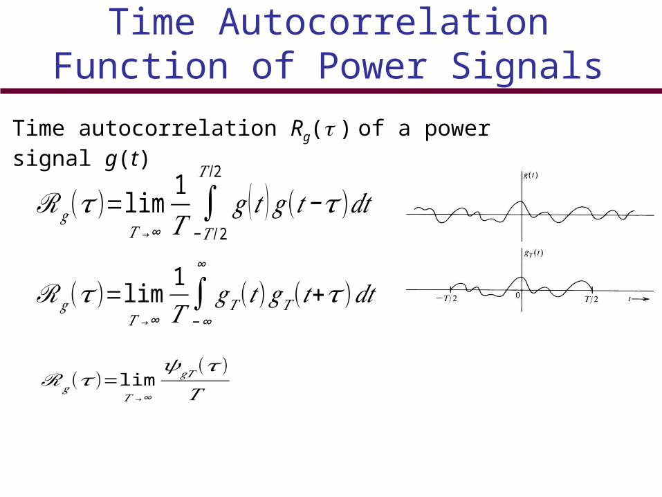
Time Autocorrelation Function of Power Signals
Time autocorrelation Rg( ) of a power signal g(t)
ℛ𝑔(𝜏 )= lim𝑇 → ∞
1𝑇 −∞
∞
𝑔𝑇 (𝑡)𝑔𝑇 (𝑡+𝜏 )𝑑𝑡
ℛ𝑔(𝜏 )= lim𝑇 → ∞
𝜓𝑔𝑇(𝜏 )𝑇
ℛ𝑔(𝜏 )= lim𝑇 → ∞
1𝑇
−𝑇 /2
𝑇 /2
𝑔 (𝑡 )𝑔(𝑡−𝜏)𝑑𝑡

Autocorrelation a Powerful Tool
If the energy or power spectral density can be found by the Fourier transform of the signal g(t) then why do we need to find the time autocorrelation?
Ans: In communication field and in general the signal g(t) is not deterministic and it is probabilistic function.

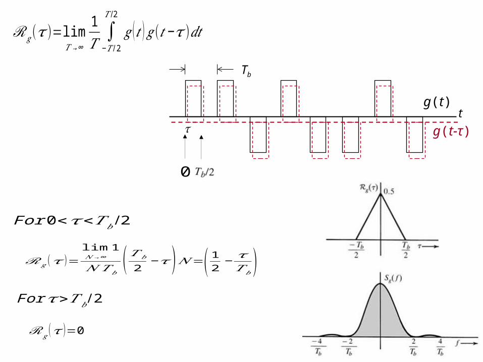
Example
A random binary pulse train g(t). The pulse width is Tb/2, and one binary digit is transmitted every Tb seconds. A binary 1 is transmitted by positive pulse, and a binary 0 is transmitted by negative pulse. The two symbols are equally likely and occur randomly. Determine the PSD and the essential bandwidth of this signal.
Challenge: g(t) is not deterministic and can not be expressed mathematically to find the Fourier transform and PSD. g(t) is random signal.
1 1 0 1 0 0 1 0
0
g(t)
𝜏 g(t-τ)
Tb
t
ℛ𝑔(𝜏 )= lim𝑇 → ∞
1𝑇
−𝑇 /2
𝑇 /2
𝑔 (𝑡 )𝑔(𝑡−𝜏)𝑑𝑡
For 0<𝜏<𝑇 𝑏/2
ℛ𝑔 (𝜏 )=lim𝑁 → ∞
1
𝑁 𝑇𝑏(𝑇𝑏
2−𝜏)𝑁=( 1
2−𝜏𝑇 𝑏
)For 𝜏>𝑇𝑏 /2
ℛ𝑔 (𝜏 )=0

𝑇 𝑏/2<𝜏<𝑇 𝑏
ℛ𝑔 (𝜏 )=lim𝑁 → ∞
1
𝑁 𝑇𝑏(𝑘𝑇𝑏+𝜏+
𝑇 𝑏
2−(𝑘+1)𝑇 𝑏)𝑁4
𝑇 𝑏/2 𝑇 𝑏
1
ℛ𝑔 (𝜏 )
𝑘𝑇𝑏
𝜏
𝑘𝑇𝑏+𝜏𝑘𝑇𝑏+𝜏+𝑇𝑏 /2
(𝑘+1)𝑇𝑏
−𝑇 𝑏/2−𝑇 𝑏
ℛ𝑔 (𝜏 )=14 ( 𝜏𝑇𝑏
−12 )
Homework Problem

Discrete Fourier Transform (DFT, FFT)
𝐺𝑞=∑𝑘=0
𝑁0 − 1
𝑔𝑘𝑒− 𝑗𝑞Ω0𝑘
Ω 0=2𝜋𝑁 0
𝑁 0=𝑇 0
𝑇 𝑠
Related Documents