CAN/CAN-Gateway CG-ARM7/RMD User Manual EMS THOMAS WÜNSCHE Sonnenhang 3 D-85304 Ilmmünster Tel +49-8441-490260 Fax +49-8441-81860 .

Welcome message from author
This document is posted to help you gain knowledge. Please leave a comment to let me know what you think about it! Share it to your friends and learn new things together.
Transcript

CAN/CAN-Gateway
CG-ARM7/RMD
User Manual
EMSTHOMAS WÜNSCHE
Sonnenhang 3
D-85304 Ilmmünster
Tel +49-8441-490260
Fax +49-8441-81860
.

User manual CG-ARM7/ RMD
Document version: 2.00Documentation date: June 22nd, 2005
No part of this document or the software described herein maybe reproduced in any form without prior written agreementfrom EMS Dr. Thomas Wünsche.
For technical assistance please contact:
EMS Dr. Thomas WünscheSonnenhang 3
D-85304 Ilmmünster
Tel. +49-8441-490260Fax +49-8441-81860
Our products are continuously improved. Due to this factspecifications may be changed at any time and withoutannouncement.
WARNING: EMS hardware and software may not beused in applications where damage to life,health or private property may result fromfailures in or caused by these components.
CAN/CAN - Gateway CG-ARM7/RMD
ii User Manual

Table of contents
1 Overview . . . . . . . . . . . . . . . . . . . . . 1
1.1 Features . . . . . . . . . . . . . . . . . . . . . 1
1.2 General description. . . . . . . . . . . . . . . . 1
1.3 Ordering information . . . . . . . . . . . . . . . 1
2 Handling . . . . . . . . . . . . . . . . . . . . . 2
2.1 Connection . . . . . . . . . . . . . . . . . . . . 2
2.2 Operation . . . . . . . . . . . . . . . . . . . . . 2
2.3 Configuration . . . . . . . . . . . . . . . . . . . 2
2.3.1 Configuration file . . . . . . . . . . . . . . . . . 3
2.3.2 Programming the device . . . . . . . . . . . . . 9
2.4 Display . . . . . . . . . . . . . . . . . . . . . 12
3 Technical specifications. . . . . . . . . . . . 14
3.1 Pin assignment . . . . . . . . . . . . . . . . . 14
3.2 Limiting values . . . . . . . . . . . . . . . . . 15
3.3 Nominal values . . . . . . . . . . . . . . . . . 15
4 Appendix . . . . . . . . . . . . . . . . . . . . 16
4.1 Configuration file sample . . . . . . . . . . . . 16
4.2 Standard baudrates . . . . . . . . . . . . . . . 17
CG-ARM7/RMD CAN/CAN - Gateway
User Manual iii

1 Overview
1.1 Features• Connection of two physically separated
CAN networks
• Filtering and mapping of identifiers
• Bus activity displayed by LED
• Gateway configuration via RS232 or CAN
• Wiring using a multiway connector
1.2 General description
The CAN/CAN gateway CG-ARM7 connectstwo physically divided CAN networks. The ca-pability of having individual baudrates on bothsegments, enables routing between them.
The filtering of single identifiers or ranges ofidentifiers lessens the busload. The mappingof single or ranges of identifiers qualifiesCG-ARM7 to be used under difficult higherlevel protocol conditions.
The device is configured via serial interface orvia CAN network. Due to the intuitive structureof the configuration file in ASCII format,programming and administration is very easy.
1.3 Ordering information
12-20-401-10 CG-ARM7/RMD
CG-ARM7/RMD CAN/CAN - Gateway
User Manual 1

2 Handling
2.1 Connection
The CG-ARM7 possesses a multiway connec-tor for flexible wiring of the CAN interfaces andthe power supply. The RS232 interface on thedevice is used for programming and for theoutput of diagnostic information. For normaloperation it is not required.
The connector assignment of the multiwayconnector and the RS232 interface is locatedin chapter “3.1 Pin assignment” in this manualor on your devices front panel.
2.2 Operation
To start up the gateway just connect the powersupply, the device starts automatically. Assoon as the automatic diagnostics is comple-ted successfully, the green power LED lites uppermantly.
Important note: Ex factory the device offersno configuration and must be configured befo-re it is first run. Configuration instructions forthe gateway are located in chapter “2.3 Confi-guration”.
2.3 Configuration
The gateway configuration process consists oftwo steps:
• Creating a configuration file
CAN/CAN - Gateway CG-ARM7/RMD
2 User Manual

• Storing the configuration file into thegateway
2.3.1 Configuration file
The configuration file is a text file with the ex-tension *.gcf. This file holds all data needed bythe gateway for operation. A complete sampleconfiguration is located in chapter “4.1 Confi-guration file”.
The values can either be entered in decimal orhexadecimal notation. Using the hexadecimalnotation, put the character “x” directly beforethe particular value.
There are two types of parameters, generalparameters and routing settings. Generalparameters include operating information forthe gateway. Routing settings are used formapping and filtering of identifiers.
Some parameters are optional. If they are notdefined, the gateway uses default settings.
Simultaneous programming of several devicesis not possible. It must be guaranteed, thateach device can be clearly identified.
In the following all parameters are listed anddescribed.
# comment
The configuration file can be provided withcomments. Comments are prefaced with thecharacter “#” and they end with the particularline.
CG-ARM7/RMD CAN/CAN - Gateway
User Manual 3
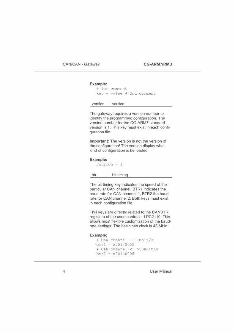
Example:# 1st commentkey = value # 2nd comment
version version
The gateway requires a version number toidentify the programmed configuration. Theversion number for the CG-ARM7 standardversion is 1. This key must exist in each confi-guration file.
Important: The version is not the version ofthe configuration! The version display whatkind of configuration is be loaded!
Example:version = 1
btr bit timing
The bit timing key indicates the speed of theparticular CAN channel. BTR1 indicates thebaud rate for CAN channel 1, BTR2 the baud-rate for CAN channel 2. Both keys must existin each configuration file.
This keys are directly related to the CANBTRregisters of the used controller LPC2119. Thisallows most flexible customization of the baud-rate settings. The basic can clock is 48 MHz.
Example:# CAN channel 1: 1Mbit/sbtr1 = x00140005# CAN channel 2: 500KBit/sbtr2 = x001C0005
CAN/CAN - Gateway CG-ARM7/RMD
4 User Manual

Standard speeds recommend by CiA are loca-ted in chapter “4.2 Standard baudrates”.
pidin,
pidoutprogram identifier
The program identifiers (PIDs) are required forthe gateway configuration via CAN. If you donot want to program the gateway via CAN, youcan remove this keys from your configurationfile.
The PIDs determine which identifiers will beused for programming the gateway. “pidin” de-fines the identifier the configuration softwareuses to send requests to the gateway. The key“pidout” defines the identifier which the gate-way uses to reply to the configuration software.
For CAN channel 1 and CAN channel 2 diffe-rent PIDs can be set. But it is also possible toprogram the gateway just via one CAN chan-nel. To set the wanted identifiers for CANchannel 1 use the keys “pidin1” and “pidout1”.For CAN channel 2 use the keys “pidin2” and“pidout2”.
To use a 29-bit identifier prepend the character“x” before the particular key. Without prefix be-fore the key 11-bit identifiers will be sent.
Example:# PIDs for CAN channel 1# CAN 1: 11-bit IN-Id: 0x5pidin1 = x5# CAN 1: 29-bit OUT-Id: 0xA00xpidout1 = xA00
CG-ARM7/RMD CAN/CAN - Gateway
User Manual 5

# PIDs for CAN channel 2# CAN 2: 29-bit IN-Id: 0x6Expidin2 = x6E# CAN 2: 29-bit OUT-Id: 0x1FFExpidout2 = x1FFE
name configuration label
For easier identification of the programmedsettings, the configuration can be labeled. Theconfiguration name must not have more than32 characters and must not contain space cha-racters or tabs. If this key is missing, no namewill be assigned to the configuration.
Example:name = standard_configuration
deviceid device id
During the configuration process via CAN thedevice has to be uniquely selected in the net-work. This process is based on the serial num-ber of the device.If there is the need to have the configurationprocess independent of the serial number, adevice id can be assigned. Then the identifica-tion of the device depends on the device idand not on the serial number.Care must be taken to use a particular deviceid just once in a network, if more than one ga-teways is used.
The device id can have values between 1 and99999999.
Example:deviceid = 50
CAN/CAN - Gateway CG-ARM7/RMD
6 User Manual
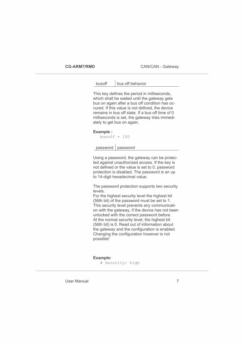
busoff bus off behavior
This key defines the period in milliseconds,which shall be waited until the gateway getsbus on again after a bus off condition has oc-cured. If this value is not defined, the deviceremains in bus off state. If a bus off time of 0milliseconds is set, the gateway tries immedi-ately to get bus on again.
Example :busoff = 100
password password
Using a password, the gateway can be protec-ted against unauthorized access. If the key isnot defined or the value is set to 0, passwordprotection is disabled. The password is an upto 14-digit hexadecimal value.
The password protection supports two securitylevels.For the highest security level the highest bit(56th bit) of the password must be set to 1.This security level prevents any communicati-on with the gateway, if the device has not beenunlocked with the correct password before.At the normal security level, the highest bit(56th bit) is 0. Read out of information aboutthe gateway and the configuration is enabled.Changing the configuration however is notpossible!
Example:# Security: high
CG-ARM7/RMD CAN/CAN - Gateway
User Manual 7
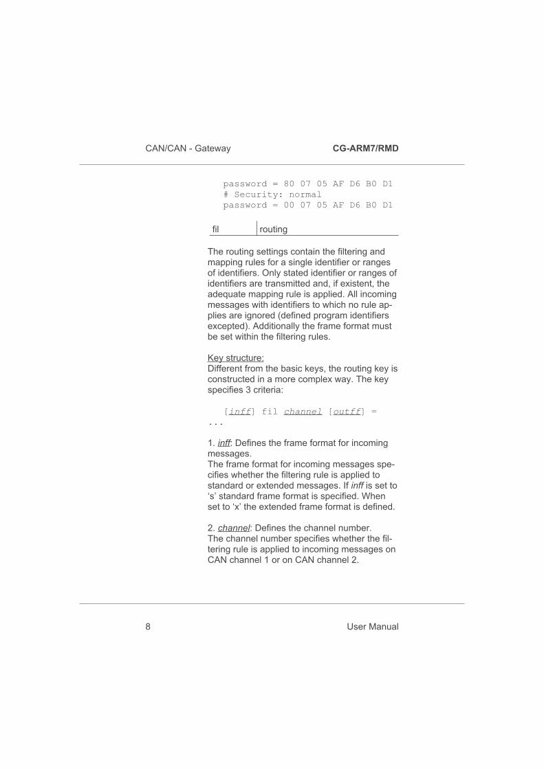
password = 80 07 05 AF D6 B0 D1# Security: normalpassword = 00 07 05 AF D6 B0 D1
fil routing
The routing settings contain the filtering andmapping rules for a single identifier or rangesof identifiers. Only stated identifier or ranges ofidentifiers are transmitted and, if existent, theadequate mapping rule is applied. All incomingmessages with identifiers to which no rule ap-plies are ignored (defined program identifiersexcepted). Additionally the frame format mustbe set within the filtering rules.
Key structure:Different from the basic keys, the routing key isconstructed in a more complex way. The keyspecifies 3 criteria:
[inff] fil channel [outff] =...
1. inff: Defines the frame format for incomingmessages.The frame format for incoming messages spe-cifies whether the filtering rule is applied tostandard or extended messages. If inff is set to‘s’ standard frame format is specified. Whenset to ‘x’ the extended frame format is defined.
2. channel: Defines the channel number.The channel number specifies whether the fil-tering rule is applied to incoming messages onCAN channel 1 or on CAN channel 2.
CAN/CAN - Gateway CG-ARM7/RMD
8 User Manual

3. outff: Defines the frame format for outgoingmessages.The frame format for outgoing messages spe-cifies whether the result of the filtering rule issent via standard or extended identifier. If outff
is set to ‘s’ standard frame format is specified.When set to ‘x’ extended frame format is defi-ned.
Structure of the filtering rule:Now that the key defines to which messagethe rule applies, further selections have to bemade. The filtering rule in turn specifies 3 crite-ria:
… = sid [- eid] [: mid]
1. sid: Defines the identifier the filtering rule isapplied to.If a range of identifiers is defined, sid is thestart identifier. If the prefix ‘x’ is before the va-lue the identifier is interpreted as a hexadeci-mal number.
2. eid: Defines the end identifier for ranges ofidentifiers.If no range of identifiers is used, the value isnot needed. If the prefix ‘x’ is before the valuethe identifier is interpreted as a hexadecimalnumber.
3. mid: Defines the mapping identifier.The mapping identifier states the start identifer,to which the single identifier or the range ofidentifiers is mapped. Should the identifiers notbe mapped it is not needed to set this value. Ifthe prefix ‘x’ is before the value the identifier isinterpreted as a hexadecimal number.
CG-ARM7/RMD CAN/CAN - Gateway
User Manual 9

Example:# The via CAN channel 1# received extended# identifiers in the range# of 0x30 to 0x40 are# sent via CAN channel 2# as standard identifiers in# the range of 0x400 to# 0x410.xfil1s = x30 - x40 : x400
# The via CAN channel 2# received extended# identifier 0x1FFFFFFF# is sent via CAN channel 1# as extended identifier# with the value 0x01.xfil2x = x1FFFFFFF : x1
# The via CAN channel 1# received standard# identifiers in the range# of 0x100 to 0x200 are# sent via CAN channel 2# as standard identifiers# in the range of 0x100# to 0x200.sfil1s = x100 - x200
2.3.2 Programming the device
CG-ARM7 is programmed by means of theconfiguration software. It offers the possibilityto configure the gateway via serial connectionor via CAN. For the configuration a serial cableor a PC-CAN interface of EMS Dr. ThomasWuensche is needed.
CAN/CAN - Gateway CG-ARM7/RMD
10 User Manual

Setting up the PC interface:The PC interface is set in the upper left field.First you choose, if the gateway shall be ac-cessed via RS232 or via CAN interface. If theconfiguration software recognizes, that you donot use an interface of EMS Dr. Thomas Wu-ensche you can not select CAN as your inter-face.Next the PC interface with which you want toconnect to the CG-ARM7 has to be chosen. Ifyou have selected RS232 as interface before,you set up the COM interface here. If you havechosen CAN, you select your CAN interfacehere.Speed can only be selected, when a connecti-on via CAN has been made. Choose a stan-dard baudrate compliant to the CiA or choose“Custom” to insert a user defined setting. Yourselected baudrate must be the same as thebaudrate of the gateway.
If no configuration is in the gateway it is notpossible to communicate with the gateway viaCAN.
CG-ARM7/RMD CAN/CAN - Gateway
User Manual 11

Process selection:In the right upper field of the configuration soft-ware you choose the process, you want toperform.
• Program new configurationWith this process you can program anew configuration to the device. Beforestarting you have to select the configu-ration you want to write to the gateway.
• Remove configuration from deviceThis process deletes the current confi-guration on the CG-ARM7. Afterwardsthe gateway is in delivery state again. Itis not needed to delete the configurationbefore a new one is programed, as thisis done automatically.
• Read device information
Here information about the gateway andthe configuration within can be read out.
CAN/CAN - Gateway CG-ARM7/RMD
12 User Manual

Optional device settingsIf the CG-ARM7 is password protected, youmust activate the field “password” and fill in thecorrect password. Depending on the securitylevel, it is possible to request information aboutthe device even without password.
If CAN has been chosen as the PC interfacethe “Inbound Program Identifier” (pidin), the“Outbound Program Identifier” (pidout) and theframe format for the program identifiers haveto be set. At last the serial number or the confi-gured device id of the device has to be inscri-bed for explicit identification. If you use onlyone gateway in the network, you can also ins-cribe the value ‘0’ here. Never use the value‘0’, if there are more than one CG-ARM7 gate-ways in the network.
Starting the download:To start the download process press start. Theoperation may take a while, do not disconnectthe power supply to the device during the con-figuration process. At that time the routingfunctionality of the gateway is deactivated. Af-ter successful completion no status messageis displayed. If an error occures a status mes-sage is displayed.
2.4 Display
The device status is displayed by three LEDs.
Power
OnThe device is in normal operationmode. Routing of CAN messages isenabled.
CG-ARM7/RMD CAN/CAN - Gateway
User Manual 13

BlinkingThe device is in programming mode.Routing of CAN messages isdisabled.
CAN 1 Active
On There is bus activity on CAN 1.
CAN 2 Active
On There is bus avtivity on CAN 2.
CAN/CAN - Gateway CG-ARM7/RMD
14 User Manual

3 Technical Data
3.1 Pin assignment
Pin assignment of the multiway connector
Pin Signal Description
1 +24V +24 Volt power supply
2 GND Ground*
3 GND Ground*
4 CAN1-H CAN1-High Buswire
5 CAN1-L CAN1-Low Buswire
6 GND Ground*
7 CAN2-H CAN2-High Buswire
8 CAN2-L CAN2-Low Buswire
* Internal connected
Pin assignment RS232
Pin Signal Description
1 not connected
2 RxD Receive signal
3 TxD Transmit signal
4 not connected
5 GND Ground
6 not connected
7 RTS not used
8 CTS not used
9 not connected
CG-ARM7/RMD CAN/CAN - Gateway
User Manual 15

3.2 Limiting values
Stresses above the specified values can leadto permanent damage of the CG-ARM7.
Parameter Min. Max. Unit
Storage temperature -20 80 C
Operating temperature 0 60 C
Supply voltage -100 30 V
Note: With respect to methods of measurement it isnot possible to have ESD protection circuits atthe CAN terminals. ESD protection on this ter-minals is determined by the ESD capability ofthe used CAN transceiver (Philips 82C251).
3.3 Nominal values
Parameter Min. Max. Unit
Supply voltage 10 30 V
Baudrates 10 1000 kBit/s
CAN/CAN - Gateway CG-ARM7/RMD
16 User Manual
4 Appendix
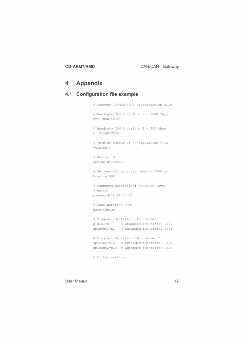
4.1 Configuration file example
# Gateway CG-ARM7/RMD configuration file
# Baudrate CAN interface 1 - 1000 kbps
btr1=x00140005
# Baudrate CAN interface 2 - 500 kbps
btr2=x001C0005
# Version number of configuration file
version=1
# Device ID
deviceid=120000
# Set bus off recovery time to 1000 ms
busoff=1000
# Password protection: security level
# normal
password=11 AA 33 BC
# Configuration name
name=router
# Program identifier CAN channel 1
pidin1=x1 # Standard identifier 0x01
xpidout1=x2 # Extended identifier 0x02
# Program identifier CAN channel 2
xpidin2=x10 # Extended identifier 0x10
xpidout2=x20 # Extended identifier 0x20
# Filter settings
CG-ARM7/RMD CAN/CAN - Gateway
User Manual 17
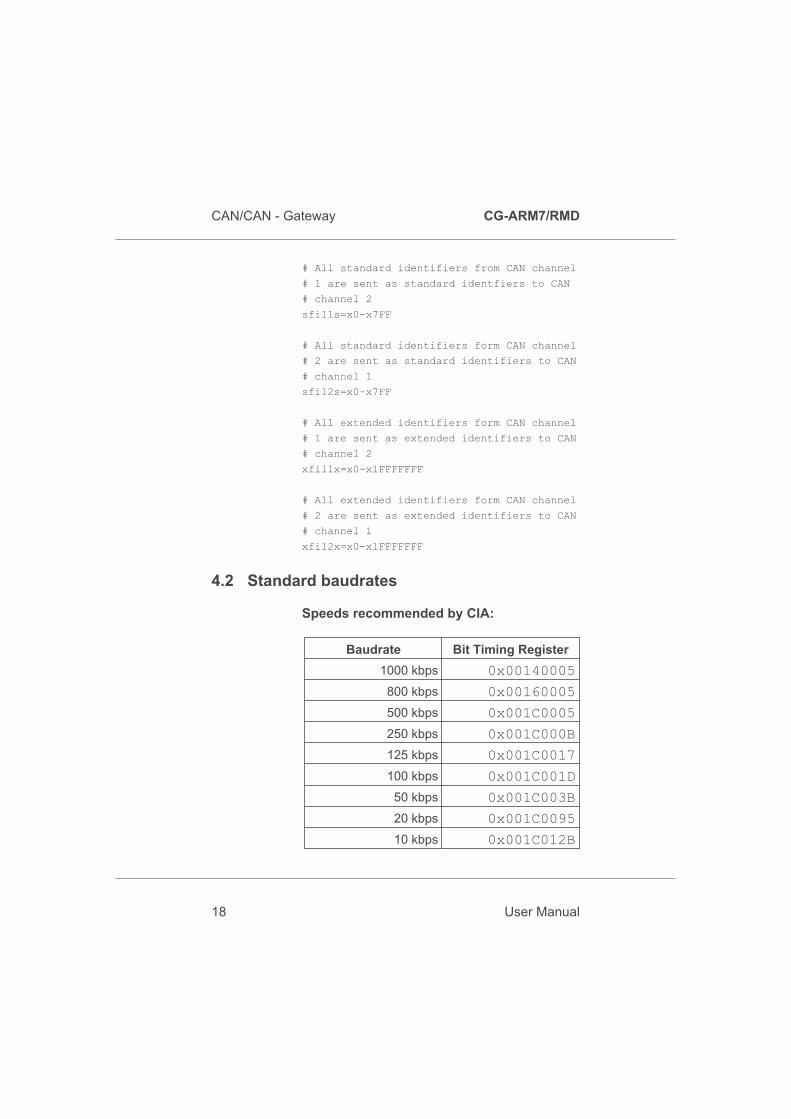
# All standard identifiers from CAN channel
# 1 are sent as standard identfiers to CAN
# channel 2
sfil1s=x0-x7FF
# All standard identifiers form CAN channel
# 2 are sent as standard identifiers to CAN
# channel 1
sfil2s=x0-x7FF
# All extended identifiers form CAN channel
# 1 are sent as extended identifiers to CAN
# channel 2
xfil1x=x0-x1FFFFFFF
# All extended identifiers form CAN channel
# 2 are sent as extended identifiers to CAN
# channel 1
xfil2x=x0-x1FFFFFFF
4.2 Standard baudrates
Speeds recommended by CIA:
Baudrate Bit Timing Register
1000 kbps 0x00140005
800 kbps 0x00160005
500 kbps 0x001C0005
250 kbps 0x001C000B
125 kbps 0x001C0017
100 kbps 0x001C001D
50 kbps 0x001C003B
20 kbps 0x001C0095
10 kbps 0x001C012B
CAN/CAN - Gateway CG-ARM7/RMD
18 User Manual

THIS PAGE INTENTIONALLY LEFT BLANK
CG-ARM7/RMD CAN/CAN - Gateway
User Manual 19
Related Documents