Design Manual for Roads and Bridges Drainage General information CG 501 Design of highway drainage systems (formerly HD 33/16, TA 80/99) Revision 2 Summary This document contains the over-arching requirements for drainage design on highways. Application by Overseeing Organisations Any specific requirements for Overseeing Organisations alternative or supplementary to those given in this document are given in National Application Annexes to this document. Feedback and Enquiries Users of this document are encouraged to raise any enquiries and/or provide feedback on the content and usage of this document to the dedicated Highways England team. The email address for all enquiries and feedback is: [email protected] This is a controlled document.

Welcome message from author
This document is posted to help you gain knowledge. Please leave a comment to let me know what you think about it! Share it to your friends and learn new things together.
Transcript
Design Manual for Roads and Bridges
DrainageGeneral information
CG 501Design of highway drainage systems(formerly HD 33/16, TA 80/99)
Revision 2
SummaryThis document contains the over-arching requirements for drainage design on highways.
Application by Overseeing OrganisationsAny specific requirements for Overseeing Organisations alternative or supplementary to those given in this documentare given in National Application Annexes to this document.
Feedback and EnquiriesUsers of this document are encouraged to raise any enquiries and/or provide feedback on the content and usageof this document to the dedicated Highways England team. The email address for all enquiries and feedback is:[email protected]
This is a controlled document.

CG 501 Revision 2 Contents
Contents
Release notes 3
Foreword 4Publishing information . . . . . . . . . . . . . . . . . . . . . . . . . . . . . . . . . . . . . . . . . . . . . . . . 4Contractual and legal considerations . . . . . . . . . . . . . . . . . . . . . . . . . . . . . . . . . . . . . . . . 4
Introduction 5Background . . . . . . . . . . . . . . . . . . . . . . . . . . . . . . . . . . . . . . . . . . . . . . . . . . . . . . 5Assumptions made in the preparation of this document . . . . . . . . . . . . . . . . . . . . . . . . . . . . . 5Mutual Recognition . . . . . . . . . . . . . . . . . . . . . . . . . . . . . . . . . . . . . . . . . . . . . . . . . 5
Abbreviations and symbols 6
Terms and definitions 7
1. Scope 11Aspects covered . . . . . . . . . . . . . . . . . . . . . . . . . . . . . . . . . . . . . . . . . . . . . . . . . . . 11Implementation . . . . . . . . . . . . . . . . . . . . . . . . . . . . . . . . . . . . . . . . . . . . . . . . . . . 11Use of GG 101 . . . . . . . . . . . . . . . . . . . . . . . . . . . . . . . . . . . . . . . . . . . . . . . . . . . . 11
2. Design principles 12Background . . . . . . . . . . . . . . . . . . . . . . . . . . . . . . . . . . . . . . . . . . . . . . . . . . . . . . 12Destinations for road runoff . . . . . . . . . . . . . . . . . . . . . . . . . . . . . . . . . . . . . . . . . . . . . 13General requirements . . . . . . . . . . . . . . . . . . . . . . . . . . . . . . . . . . . . . . . . . . . . . . . . 15
3. Road drainage design selection 16General . . . . . . . . . . . . . . . . . . . . . . . . . . . . . . . . . . . . . . . . . . . . . . . . . . . . . . . . 16Surface water drainage design . . . . . . . . . . . . . . . . . . . . . . . . . . . . . . . . . . . . . . . . . . . 23
Kerb and gully drainage . . . . . . . . . . . . . . . . . . . . . . . . . . . . . . . . . . . . . . . . . . . . 23Combined drainage . . . . . . . . . . . . . . . . . . . . . . . . . . . . . . . . . . . . . . . . . . . . . . . . . 23Sub-surface drainage design . . . . . . . . . . . . . . . . . . . . . . . . . . . . . . . . . . . . . . . . . . . . 24
Embankments and cuttings . . . . . . . . . . . . . . . . . . . . . . . . . . . . . . . . . . . . . . . . . . 24Groundwater . . . . . . . . . . . . . . . . . . . . . . . . . . . . . . . . . . . . . . . . . . . . . . . . . . 24
4. Climate change 26Climate change allowances . . . . . . . . . . . . . . . . . . . . . . . . . . . . . . . . . . . . . . . . . . . . . 26
5. Storm flows and flood risk 27
6. Drainage from adjacent land 28Drainage from adjacent land . . . . . . . . . . . . . . . . . . . . . . . . . . . . . . . . . . . . . . . . . . . . 28
New and existing connections . . . . . . . . . . . . . . . . . . . . . . . . . . . . . . . . . . . . . . . . . 28Management of land drainage . . . . . . . . . . . . . . . . . . . . . . . . . . . . . . . . . . . . . . . . . 28
7. Road geometry 29Drainage of superelevated carriageways . . . . . . . . . . . . . . . . . . . . . . . . . . . . . . . . . . . . . . 29Drainage of wide carriageways . . . . . . . . . . . . . . . . . . . . . . . . . . . . . . . . . . . . . . . . . . . 29
Drainage flow paths . . . . . . . . . . . . . . . . . . . . . . . . . . . . . . . . . . . . . . . . . . . . . . 29Effect of carriageway edge markings . . . . . . . . . . . . . . . . . . . . . . . . . . . . . . . . . . . . . 36Crossfalls . . . . . . . . . . . . . . . . . . . . . . . . . . . . . . . . . . . . . . . . . . . . . . . . . . . . 36
8. Pollution and flow control design 37Principles of pollution and flow control . . . . . . . . . . . . . . . . . . . . . . . . . . . . . . . . . . . . . . . 37Selection of pollution and flow control measures . . . . . . . . . . . . . . . . . . . . . . . . . . . . . . . . . 37Signage of pollution control devices . . . . . . . . . . . . . . . . . . . . . . . . . . . . . . . . . . . . . . . . 41
9. Normative references 43
1
CG 501 Revision 2 Contents
10. Informative references 44
Appendix A. Drainage option advantages and disadvantages 45
Appendix B. Pollution control components 52
2

CG 501 Revision 2 Release notes
Release notesVersion Date Details of amendments2 Mar 2020 Revision 2 (March 2020) Revision to update references and typographical
errors in clauses 3.18 and 3.19 where formation has been changed tosub-formation. Clause 3.9 from previous revision related to performancerequirements specified in the design of a kerb and gully drainage system hasbeen deleted as it is superfluous. Revision 1 (December 2019) contains aminor revision to Table 8.6.4N3. The stated suspended solids % removal fordry/detention basins has been amended from 5% to 50% which was atypographical error. Clause 4.10 that referenced IAN 161 has been deleted asthis was a cyclical reference and is not required. Revision 0 (October 2019)CG 501 replaces HD 33/16 and TA 80/99. This full document has beenre-written to make it compliant with the new Highways England drafting rules.
3

CG 501 Revision 2 Foreword
Foreword
Publishing informationThis document is published by Highways England.
This document supersedes CG 501 revision 1.
Contractual and legal considerationsThis document forms part of the works specification. It does not purport to include all the necessaryprovisions of a contract. Users are responsible for applying all appropriate documents applicable totheir contract.
4

CG 501 Revision 2 Introduction
Introduction
BackgroundThis document sets out requirements and provides recommendations on the design of drainage for theUK motorway and all-purpose trunk roads. It describes the various alternative drainage solutions thatare available, including their potential to control pollution and flooding, as well as detailed designfactors to be taken into account.
Road drainage can be broadly split into two categories: surface and sub-surface drainage. Generallyspeaking, road surfacing materials are effectively impermeable, and rainfall which does not permeatethe carriageway surface is shed towards the edges of the pavement and into surface water drainagesystems. Surface water can also infiltrate into road foundations, earthworks or structures through anysurface which is not completely impermeable, and as such sub-surface drainage is utilised to allowsuch water to drain through underlying pavement layers and away from the formation.
The types of drainage discussed in this standard are one element of road drainage. Other elementsinclude:
1) outfalls and culverts - see CD 529 [Ref 3.N];
2) soakaways - see CD 530 [Ref 3.I];
3) reservoir pavements - see CD 531 [Ref 9.I];
4) sumpless gullies - see CD 527 [Ref 10.I];
5) chamber tops and gully tops - see CD 534 [Ref 1.I];
6) certification of drainage design - see CG 502 [Ref 18.N].
Surface drainage is achieved through collection of surface water runoff from the pavement (andpotentially adjacent land) through formal (e.g. kerbs and gullies) or informal (over the edge) drainage,discharging into longitudinal surface channels or piped systems.
Sub-surface drainage is achieved by installation of longitudinal sub-surface drains situated in vergesand/or central reserves at the low edges of road pavements. These drain the pavement layers and thepavement foundation (pavement and capping layers are contiguous with the side of the trench) andprevent ingress of water from verge areas adjacent to the pavement.
Drainage designs may utilise combined systems (where both surface water and sub-surface water arecollected in the same pipe) or separate systems (where sub-surface water is collected in a separatedrainage conduit from the one which is used for collection of surface water).
Assumptions made in the preparation of this documentThe assumptions made in GG 101 [Ref 11.N] apply to this document.
Mutual RecognitionWhere there is a requirement for compliance with any part of a "British Standard" or other technicalspecification, that requirement may be met by compliance with the Mutual Recognition clause in GG101 [Ref 11.N].
5

CG 501 Revision 2 Abbreviations and symbols
Abbreviations and symbols
AbbreviationsAbbreviation DefinitionEQS Environmental Quality Standard
GWQS Groundwater Quality Standard
MCHW Manual of Contract Documents for Highways Works
NG Notes for Guidance
PAHs Polycyclic Aromatic Hydrocarbons
PCD Pollution Control Device
PCS Pollution control sign
SHW Specification for Highways Works
SPZ Source Protection Zone
SuDS Sustainable Drainage Systems
VRS Vehicle Restraint System
WFD Water Framework Directive
Symbols
Symbol Definition
FL flow control
F fin drain
GSWC grassed surface water channel
NF narrow filter drain
O other pollution control mechanisms
S spillage control
SW surface water channel
V vegetated systems
Y yes
Xremoval of pollutants likely to occur but insufficient evidence available to quote indicativetreatment efficiency
6

CG 501 Revision 2 Terms and definitions
Terms and definitions
TermsTerm Definition
Catchpit Small chamber that road runoff passes through,incorporating sediment collection sump.
Combined channel and pipe drainage
Crushed stone/shingle filter medium over a perforated orporous carrier pipe. Drains both surface water from thepavement and groundwater to protect the pavementconstruction.
Combined kerb and drainage Monolithic kerbs with internal drainage channel linked toopenings in the kerb face.
Combined surface and sub-surface drain
System of filter drainage that comprises a perforated,porous or open jointed carrier pipe, bedded in granularmaterial, in a trench that is then backfilled with a granularfilter material of Type A, B or C as defined in MCHWSeries 500 [Ref 13.N].
Crossfall The slope on the road at right angles to the direction oftravel.
Crown line The line on the road where the crossfall changes.
Detention basin
Landscaped depression that is normally dry except duringand following rainfall events, designed to temporarilystore water to attenuate flows and, where vegetated,provide treatment of pollution.
Fin drain
A planar geocomposite arrangement designed to removesub-surface moisture from beneath the pavement.
NOTE: This can solely comprise a core surrounded bytextile, or incorporate a pipe within the geotextile wrap.
First flush
The runoff from the first part of a rainfall event.
NOTE: This usually is the most polluted runoff, especiallywhen there is intense rainfall after long dry periods duringwhich pollutants can accumulate on the road.
Flood plainAny land with a 1 in 100 or greater annual probability ofriver flooding or a 1 in 200 or greater annual probability ofsea flooding.
Flow pathThe flow path is the route taken by rainfall runoff from thepoint at which it falls on the carriageway surface to thecarriageway edge.
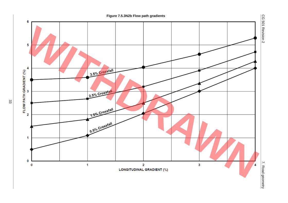
Flow path gradient
The overall net gradient produced from a combination ofthe longitudinal gradient and crossfall gradient (whenchanging from a superelevated carriageway tonon-superelevated carriageway).
Grassed surface water channelGrassed triangular or trapezoidal surface water channelthat is installed at the pavement edge to collect andconvey rainfall runoff from the road surface.
7

CG 501 Revision 2 Terms and definitions
Terms (continued)
Term Definition
GroundwaterAll water which is below the surface of the ground in thesaturation zone (below the water table) and in directcontact with the ground or subsoil.
HandstopFlat plate, fitted to a pair of guide slots on a headwall orchamber wall, which can be raised and lowered manually(rather than screw thread as per penstocks).
Hard shoulder A nearside lane adjacent to a carriageway, for emergencyuse.
Hazardous substance
Substances or groups of substances that are toxic,persistent and liable to bio-accumulate, and othersubstances or groups of substances which give rise to anequivalent level of concern.
NOTE: In accordance with the 2000/60/EC [Ref 4.I].
High water table level Maximum permitted level of the groundwater tablebeneath the road sub-formation.
Infiltration basinDry basin designed to promote infiltration of surface waterinto the ground.
Informal drain (over the edge)An arrangement where surface water flows off thecarriageway and across the verge to a drainage system,usually a ditch.
Kerb and gully drainage
System of drainage whereby surface water is directed byedge of pavement kerbs into gullies which are connectedto a longitudinal carrier drain or pipe set within the roadverge.
Linear drainage channel A closed profile hydraulic conduit with slots or holeslocated in the top.
Narrow filter drainAn edge of pavement subsurface drain that comprisesfilter material and a carrier pipe, which can be wrapped ina geotextile.
Penstock
Flat plate, fitted to a pair of guide slots on a headwall orchamber wall, which can be raised and lowered using ascrew thread operated by a wheel in order to controlspillages.
Pollution The direct or indirect introduction, as a result of humanactivity, of substances or heat into the air, water or landwhich can be harmful to human health or the quality ofaquatic ecosystems (or terrestrial ecosystems directlydepending on aquatic ecosystems) which result indamage to material property, or which impair or interferewith amenities and other legitimate uses of theenvironment.
NOTE: In accordance with the 2000/60/EC [Ref 4.I].
Pervious asphalt Asphalt material used to make pavement layers perviouswith open voids to allow water to pass through.
8

CG 501 Revision 2 Terms and definitions
Terms (continued)
Term Definition
Reasonably practicable
Something that is achievable without disproportionatelevel of complexity or having an impact on other designelements or construction, installation or maintenance ofthose elements.
NOTE: Issues for consideration can include sewercapacity, maintenance responsibilities, capital andmaintenance costs etc.
Reservoir pavement
Pavement where rainfall percolates through the perviousroad surfacing, or runoff is diverted via gullies, edgedrains and pipes into a porous sub-base material(reservoir).
NOTE: Here, rain water accumulates before it slowlypercolates into the soil subgrade or discharges throughdrains into the main surface water drainage system.
Retention pond
Pond that generally retains some water at all times. Canhave permeable base or banks. Primarily designed toattenuate flows by accepting large inflows, butdischarging slowly. Can also treat water by allowingsuspended solids to settle out.
Roll-over lengths Lengths of carriageway where the crossfall is varied forthe provision/purpose of superelevation.
Sedimentation tank
A contained structure that allows suspended particles tosettle out of water as it flows slowly through the tank,providing a degree of purification.
NOTE: A layer of accumulated sludge collects at the baseof the tank and needs periodic removal.
Soakaway Sub-surface structure into which surface water isconveyed and which aids infiltration.
Source Protection Zone
Zones designated around public water supplyabstractions and other sensitive receptors that show therisk of contamination from any activities that can causepollution in the area.
Superelevated carriageway Carriageway with a curved horizontal alignment wherethe crossfall slopes towards the inside of the bend.
Surface water body
Inland waters (except groundwater), transitional watersand coastal waters.
NOTE: In accordance with the 2000/60/EC [Ref 4.I].
Surface water channel (includingchannel blocks)
Triangular, trapezoidal or rectangular cross sectionchannel, formed from asphalt or concrete, located nearthe edge of the carriageway, used to collect and conveysurface water from the road.
9

CG 501 Revision 2 Terms and definitions
Terms (continued)
Term Definition
SwaleA wide shallow grassed channel, normally locatedadjacent to a carriageway but often separated by asection of verge.
WetlandA pond with a high proportion of shallow zones thatpromote the growth of bottom-rooted plants and whichcan be used for treatment of pollution.
10

CG 501 Revision 2 1. Scope
1. Scope
Aspects covered1.1 The methods and design requirements in this document shall be applied where the design of new
drainage is undertaken.
Implementation1.2 This document shall be implemented forthwith on all schemes involving design of drainage on the
Overseeing Organisations' motorway and all-purpose trunk roads according to the implementationrequirements of GG 101 [Ref 11.N].
Use of GG 1011.3 The requirements contained in GG 101 [Ref 11.N] shall be followed in respect of activities covered by
this document.
11

CG 501 Revision 2 2. Design principles
2. Design principles
Background2.1 The design of surface and sub-surface drainage in UK motorway and all-purpose trunk roads shall:
1) remove surface water from the carriageway as quickly as possible to provide safety and minimumnuisance to the road users;
2) maximise longevity of the pavement and its associated earthworks;
3) minimise the impact of the runoff on the receiving environment in terms of flood risk and waterquality; and
4) manage water flows from earthworks and structures associated with the roads.
2.2 Designs must be undertaken in accordance with the Construction (Design and Management)Regulations SI 2015/51 [Ref 19.N].
2.3 Drainage design shall be integrated such that drainage of the road, water quality and flood risksimultaneously meet the requirements given in the remainder of the DMRB.
NOTE 1 The process of integrated drainage design is illustrated in Figure 2.3.N1.
Figure 2.3N1 Integrated design approach
NOTE 2 Requirements for the design of surface and sub-surface drainage are presented in:
1) this document;2) the reference documents listed in Table 3.4;3) MCHW Series 500 [Ref 13.N];4) MCHW Series NG500 [Ref 14.N];5) Section 1, Drainage of Volume 3 of the MCHW [Ref 12.N];6) Section 1, Edge of Pavement Details of Volume 3 of the MCHW [Ref 12.N];7) CD 523 [Ref 5.N] Determination of pipe roughness and assessment of sediment deposition to aid
pipeline design;8) CD 533 [Ref 4.N] Determination of pipe and bedding combinations for drainage works;9) CD 525 [Ref 2.N] Design of combined surface and sub-surface drains and management of stone
scatter;
12
CG 501 Revision 2 2. Design principles
10) LA 113 [Ref 15.N] Road drainage and the water environment;11) CD 521 [Ref 10.N] Hydraulic design of road edge surface water channels and outlets; and12) CD 524 [Ref 8.N] Edge of pavement details.
Destinations for road runoff2.4 Road drainage shall be discharged to the following destinations in order of preference:
1) ground;
2) surface water body;
3) surface water sewer; and
4) combined sewer.
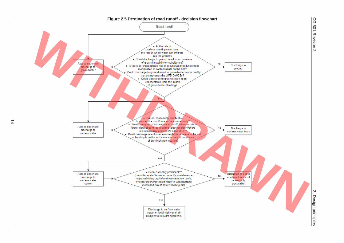
2.5 The decision process that shall be followed when determining the destination for road drainage ispresented in Figure 2.5.
13
CG501
Revision
22.
Design
principles
Figure 2.5 Destination of road runoff - decision flowchart
14
CG 501 Revision 2 2. Design principles
NOTE 1 Groundwater quality standards (GWQSs) can vary over time and between the various OverseeingOrganisations.
NOTE 2 The acceptability of different risks varies according to geographic location and is site specific.
2.6 Road drainage shall only be discharged into lakes, ponds, canals or reservoirs where a site-specificrisk assessment produced in compliance with LA 113 [Ref 15.N] demonstrates that this represents noor minimal risk to the lake, pond, canal or reservoir.
2.6.1 Discharge of road drainage to ground within a groundwater Source Protection Zone 1 (SPZ 1) shouldbe avoided EA Groundwater protection [Ref 11.I] .
NOTE Guidance on discharge of road drainage to ground within a SPZ 1 is given within LA 113 [Ref 15.N].
2.6.2 Discharge of road drainage to ground within a groundwater Source Protection Zone 2 (SPZ 2) shouldbe avoided EA Groundwater protection [Ref 11.I] though the acceptance of such is likely to require lessjustification than within a SPZ 1.
2.7 Discharge of road drainage shall not be to a foul sewer.
2.8 Where the rate of surface water runoff is greater than the rate at which water is able to infiltrate into theground, discharge to the ground shall be utilised to drain water within the capacity of the groundconditions.
2.9 Discharge to the ground shall not create an unacceptable risk of groundwater flooding, groundinstability or groundwater contamination.
2.10 Where the rate of surface water runoff is greater than the rate at which water is able to infiltrate into theground, the excess runoff shall be drained to surface water or sewer options in accordance with Figure2.5.
2.10.1 When using the decision flowchart in Figure 2.5 the potential to use mitigation measures (such as flowattenuation or SuDS) should be evaluated.
General requirements2.11 A document describing the technical basis of the drainage design shall be prepared and submitted to
the Overseeing Organisation in accordance with CG 502 [Ref 18.N].
NOTE Factors associated with baseline environment are site-specific and include catchment size, drainedareas, runoff destination, space, topography, groundwater, soil permeability, existing drainage andsensitive receptors.
2.12 The use of the decision flowchart in Figure 2.5, together with the justification for the outcomes of it,shall be recorded in the document describing the technical basis of the drainage design.
2.12.1 The drainage design should be carried out early in the design process for a project.
2.13 All drainage designs shall incorporate safety measures as required by CD 521 [Ref 10.N], CD 524 [Ref8.N], CD 525 [Ref 2.N] and CD 532 [Ref 21.N].
NOTE CD 532 [Ref 21.N] includes details of safety risk assessments and mitigation measures for open bodiesof water.
2.14 Assessment of effects of road drainage on the water environment shall be carried out in accordancewith LA 113 [Ref 15.N].
2.15 All documentation shall be managed in accordance with CD 535 [Ref 6.N].
15

CG 501 Revision 2 3. Road drainage design selection
3. Road drainage design selection
General3.1 Detailed design of carriageway drainage shall identify the range of options and recommend the most
suitable option based on site specific constraints.
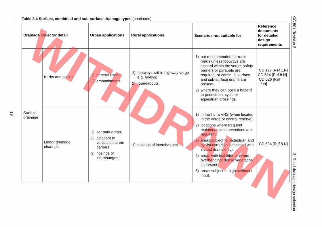
NOTE Table 3.4 presents guidance on the suitability of different types of road drainage in different scenariosand references the documents that contain detailed design advice and standards.
3.2 The design process shall determine:
1) the appropriate destination of road runoff (see Figure 2.5);
2) the design storms to be used in the design of the drainage elements within the catchment underconsideration;
3) the flows from the design storms at each drainage element within the catchment, incorporating thenecessary allowances for climate change;
4) the hydraulic adequacy of each drainage element within the catchment;
5) where necessary, the structural loadings upon drainage conduits, and verification that each conduitcan withstand the loading placed upon it;
6) the appropriate location and levels of associated outfalls and/or soakaways; and
7) where necessary, the incorporation of pollution and flood risk control measures.
3.3 Where excavation is required, the design of drainage systems shall include management of theexcavated material to minimise waste and minimise risk to human health or the environment.
3.4 Justification shall be given for the system selected for drainage, based upon the requirements statedwithin this document.
16

CG501
Revision
23.
Road
drainagedesign
selection
Table 3.4 Surface, combined and sub-surface drainage types
Drainage collector detail Urban applications Rural applications Scenarios not suitable for
Referencedocumentsfor detaileddesignrequirements
Combined channel andpipe drains
1) not generallyapplicable.
1) high- speed roads;
2) embankments where vergespace is limited.
1) areas subject to equestrian use;
2) in front of a vehicle restraintsystem (VRS) if the flow depthis greater than 150 mm;
3) within the working width behindVRS if the flow depth is greaterthan 200 mm.
CD 521 [Ref10.N]CD 524 [Ref 8.N]
Surfacedrainage
Combined kerb anddrainage system
1) areas ofcongested publicutility services;
2) shallow outlets;
3) flat long gradients;
4) roundabouts.
1) flat long gradients wherefootways within highway verge;
2) roundabouts.
1) junction or stretch of roadwhere maintenance wouldrequire road closure or complextraffic managementrequirements;
2) areas with leaf litter or whereoverhanging/ dense vegetationis present.
CD 524 [Ref 8.N]CD 127 [Ref 1.N]
17

CG501
Revision
23.
Road
drainagedesign
selection
Table 3.4 Surface, combined and sub-surface drainage types (continued)
Drainage collector detail Urban applications Rural applications Scenarios not suitable for
Referencedocumentsfor detaileddesignrequirements
Grassed surface waterchannels/swales
1) not generallyapplicable.
1) in verges for grassed surfacewater channels;
2) on gently slopingembankments for swales;
3) on areas where there is overthe edge drainage.
1) on central reserve if located atthe pavement edge;
2) where the height of anembankment exceeds the widthof a proposed channel (due tothe risk of percolationdestabilising the embankmentslope);
3) within a groundwater SPZ(unless unacceptable risk ofgroundwater pollution);
4) in front of a VRS if the flowdepth is greater than 200 mm;
5) within the working width behindVRS if the flow depth is greaterthan 200 mm.
CD 521 [Ref10.N]
Surfacedrainage
Informal drainage (overthe edge)
1) not generallyapplicable.
1) in verges;
2) embankments (but only wherethere is an open ditch orwatercourse at the base of theembankment).
1) locations where footways orsegregated cycleways abutcarriageways;
2) on structures;
3) embankments constructed ofclayey or silty soil or of depthgreater than 1.0 m and slopesteeper than 1:3 (33%).
CD 521 [Ref10.N]CD 524 [Ref 8.N]
18
CG501
Revision
23.
Road
drainagedesign
selection
Table 3.4 Surface, combined and sub-surface drainage types (continued)
Drainage collector detail Urban applications Rural applications Scenarios not suitable for
Referencedocumentsfor detaileddesignrequirements
Kerbs and gullies 1) general usage;
2) embankments.
1) footways within highway vergee.g. laybys;
2) roundabouts.
1) not recommended for ruralroads unless footways arelocated within the verge, safetybarriers or parapets arerequired, or continual surfaceand sub-surface drains arepresent;
2) where they can pose a hazardto pedestrian, cycle orequestrian crossings.
CD 127 [Ref 1.N]CD 524 [Ref 8.N]CD 526 [Ref17.N]
Surfacedrainage
Linear drainagechannels
1) car park areas;
2) adjacent tovertical concretebarriers;
3) nosings ofinterchanges.
1) nosings of interchanges.
1) in front of a VRS (when locatedin the verge or central reserve);
2) locations where frequentmaintenance interventions arerequired;
3) areas subject to pedestrian andcyclist use (risk associated withslotted drains only);
4) areas with leaf litter or whereoverhanging/ dense vegetationis present;
5) areas subject to high sedimentinput.
CD 524 [Ref 8.N]
19

CG501
Revision
23.
Road
drainagedesign
selection
Table 3.4 Surface, combined and sub-surface drainage types (continued)
Drainage collector detail Urban applications Rural applications Scenarios not suitable for
Referencedocumentsfor detaileddesignrequirements
Surfacedrainage
Surface water channels(including channelblocks)
1) not generallyapplicable.
1) high- speed roads;
2) embankments;
3) cuttings.
1) edge drains contiguous withhard shoulders, hardstrips orcarriageways (channel blocks);
2) areas subject to equestrian use;
3) in front of a VRS if the flowdepth is greater than 150 mm;
4) within the working width behindVRS if the flow depth is greaterthan 200 mm.
CD 521 [Ref10.N]CD 524 [Ref 8.N]
Com-bined
Combined surface andsub-surface drains
1) not generallyapplicable.
1) along edge of cuttings or withincentral reserve wheregroundwater levels have thepotential to interfere withoperation of a surface waterdrainage system or there islimited verge width;
2) roads with long lengths of zerolongitudinal gradient.
1) central reserves in order toreduce health and safety risksduring maintenance;
2) in narrow verges subject to useby equestrians.
CD 524 [Ref 8.N]CD 533 [Ref 4.N]CD 525 [Ref 2.N]
Fin drain 1) not generallyapplicable.
CD 524 [Ref 8.N]
Sub-surfacedrainage
Narrow filter drain 1) not generallyapplicable.
1) edge of pavement wheregroundwater ingress is notexpected to be large.
1) roads comprising rigid orflexible carriageways with overthe edge drainage;
2) roads with free drainingsubgrade;
3) areas where significantgroundwater ingress isexpected.
CD 524 [Ref 8.N]
20
CG 501 Revision 2 3. Road drainage design selection
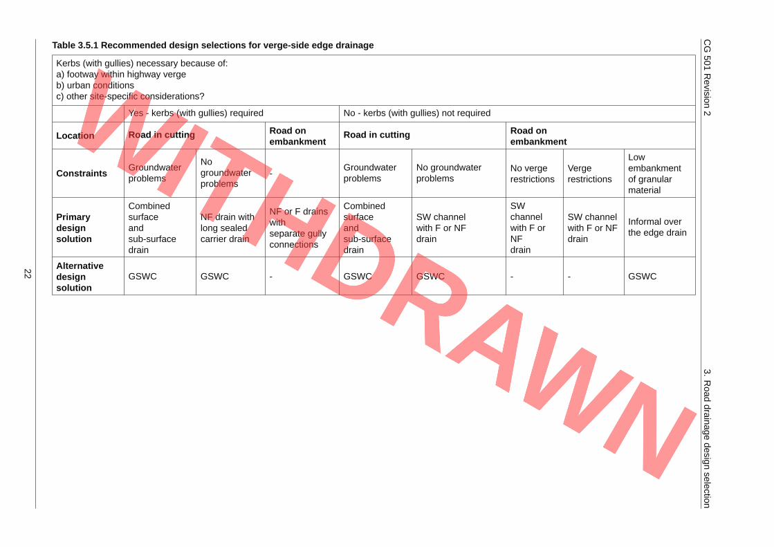
NOTE 1 Additional details on the advantages and disadvantages of these drainage types are presented inAppendix A. Tables 3.5.1 and 3.5.2 provide details of edge of pavement and central reserve drainagedesign options.
NOTE 2 The general principle of highway drainage is that surface water and sub-surface water are keptseparate as far as practically possible until the sub-surface water discharges to a chamber thatconnects to the carrier pipe. This is in order to prevent large amounts of water being introduced to theroad pavement foundation, however the use of combined drainage is preferable in certaincircumstances (see Combined drainage and Table 3.4).
3.5 Edge of pavement drains shall be included on all roads except the following, in accordance with CD524 [Ref 8.N]:
1) roads with combined surface and sub-surface drains;
2) roads comprising rigid or flexible carriageways with over the edge drainage;
3) roads with free draining subgrade.
3.5.1 The decision processes presented in Table 3.5.1 may be used to determine the most appropriate edgeof pavement drainage design.
21
CG501
Revision
23.
Road
drainagedesign
selection
Table 3.5.1 Recommended design selections for verge-side edge drainage
Kerbs (with gullies) necessary because of:a) footway within highway vergeb) urban conditionsc) other site-specific considerations?
Yes - kerbs (with gullies) required No - kerbs (with gullies) not required
Location Road in cutting Road onembankment
Road in cutting Road onembankment
Constraints Groundwaterproblems
Nogroundwaterproblems
-Groundwaterproblems
No groundwaterproblems
No vergerestrictions
Vergerestrictions
Lowembankmentof granularmaterial
Primarydesignsolution
Combinedsurfaceandsub-surfacedrain
NF drain withlong sealedcarrier drain
NF or F drainswithseparate gullyconnections
Combinedsurfaceandsub-surfacedrain
SW channelwith F or NFdrain
SWchannelwith F orNFdrain
SW channelwith F or NFdrain
Informal overthe edge drain
Alternativedesignsolution
GSWC GSWC - GSWC GSWC - - GSWC
22

CG 501 Revision 2 3. Road drainage design selection
NOTE NF – narrow filter drain F – fin drain SW – surface water channel GSWC - grassed surface waterchannel.
3.5.2 The decision processes presented in Table 3.5.2 may be used to determine the most appropriatecentral reserve drainage design.
Table 3.5.2 Recommended design selections for central reserve drainage
LocationBalancedcarriageway
Super elevated carriageway
Central reserve Paved Unpaved Paved Unpaved
Design solution F or NF drain SW channel and F or NF drain
Alternative designsolution
- - - Combined surface and sub-surfacedrain
NOTE NF – narrow filter drain F – fin drain SW – surface water channel.
3.6 Where a pavement overlay is being installed over an existing pavement, the design of the overlay shallnot compromise operation of existing pavement edge drainage.
3.7 The levels of gully grating and filter media on kerb and gully drains or combined surface andsub-surface drains shall be raised to match the new pavement level.
3.7.1 The edge of the overlay may be shaped to tie in with the top of surface water channels if it can beachieved without compromising the structural integrity of the pavement.
3.7.2 As an alternative to shaping the edge of the overlay, the existing drainage channel may be broken outand replaced at a higher level.
Surface water drainage design3.8 Where surface water edge of pavement drainage is used it shall be designed in accordance with the
requirements of this document, CD 521 [Ref 10.N], CD 524 [Ref 8.N], CD 525 [Ref 2.N] and LA 113[Ref 15.N].
Kerb and gully drainage
3.9 Kerb and gully drainage systems located within the nosing sections of junction merge and divergetapers shall be designed to withstand trafficking of the hard shoulder.
NOTE Locations such as the nosing sections of junction merge and diverge tapers commonly have low pointsin cross-section due to the direction of crossfalls.
3.10 Where kerb and gully drainage is designed in combination with fin drains, it shall not have an adverseeffect on fin drain operation.
NOTE 1 Functioning of kerb and gully systems is dependent upon the build-up of a flow of water in front of thekerb.
NOTE 2 Flows of water against the kerb face generally increase in the direction of longitudinal gradient until theflow is intercepted by a road gully.
NOTE 3 Build-up of widths of water flow, which have the potential to intrude into the hard shoulder, hardstrip orcarriageway of the highway present a hazard to vehicles.
3.11 Gully spacing shall be designed in accordance with CD 526 [Ref 17.N] .
NOTE Details of acceptable flow widths are presented in CD 526 [Ref 17.N].
3.11.1 For low embankments with toe ditches, gullies may discharge directly to the toe ditches via discreteoutlets.
23

CG 501 Revision 2 3. Road drainage design selection
Combined drainage3.12 Where combined surface and sub-surface drainage is used it shall be designed in accordance with the
requirements of this document and CD 525 [Ref 2.N].
NOTE The requirements and advice on pipe and bedding combinations in combined surface and sub-surfacedrains is presented in CD 533 [Ref 4.N].
3.13 Surface treatment or stabilisation of combined surface and sub-surface drains shall be included in thedesign at locations where the risk of stone scatter occurring is greatest (refer to CD 525 [Ref 2.N]).
NOTE Potential risks associated with combined surface and sub-surface drains include surface failure ofembankments and pavement failures.
3.13.1 To minimise surface water input at trench base level, the design of combined drainage for cuttings mayinclude pipes with sealed joints and with perforations or slots laid uppermost.
3.13.2 Lining of trench bottoms with impermeable membranes up to pipe soffit level may be used to preventinfiltration of water from the drainage system into surrounding dry sub-soil or from polluting anunderlying aquifer.
3.13.3 Separate design estimates for groundwater flow may not be needed when designing combined surfaceand sub-surface drainage for a cutting.
Sub-surface drainage design3.14 Where sub-surface drainage is used it shall be designed in accordance with CD 524 [Ref 8.N].
3.15 The design of sub-surface drainage shall include shaping of the formation and sub-formation such thatsub-surface water drains to longitudinal sub-surface drains.
3.16 Sub-surface drainage shall be designed to manage sub-surface water such that it does not reach thesub-base or capping layer of roads.
3.17 Where there is no capping, the design of fin drains and narrow filter drains shall include a depth to topof pipe greater than 50 mm below sub-formation layer (as defined in Volume 1 of MCHW [Ref 12.N]).
3.18 Drains installed with a depth to top of pipe greater than 50 mm below sub-formation layer shall bedesigned to maintain a 'high water table level' at a depth of 300 mm or greater below the roadsub-formation level.
NOTE High groundwater levels have the potential to interfere with the operation of a surface water drainagesystems.
3.18.1 To achieve the 'high water table level' or lower, fin or narrow filter drains may be installed at a greaterdepth than the minimum shown in Volume 3 of MCHW [Ref 12.N].
3.19 The design of sub-surface drainage shall not contain any low spots where water can accumulate.
3.19.1 Use of 100 mm diameter pipes within narrow filter drains, rather than pipes of smaller diameter, mayreduce future maintenance costs.
3.20 The sub-base shall be drained unless the underlying materials (capping or subgrade) are morepermeable than the sub-base, and the water table is never within 300 mm of the underside of thefoundation (in accordance with CD 225 [Ref 2.I]).
Embankments and cuttings
3.21 Sub-surface drainage in cuttings shall lower groundwater to a depth such that it does not have thepotential to interfere with the operation of a surface water drainage system (in accordance with CD 525[Ref 2.N]).
3.21.1 Circumstances in which sub-surface drainage may be omitted are described in CD 524 [Ref 8.N].
24

CG 501 Revision 2 3. Road drainage design selection
Groundwater
3.22 Sub-surface drainage shall function regardless of variations in groundwater level.
NOTE 1 Water moves partly by gravity and partly by capillary action, and these movements are susceptible tocontrol by subsoil drainage.
NOTE 2 Groundwater is subject to seasonal variations consequential to rainfall conditions, geology and soilpermeability.
3.22.1 Ground investigations undertaken to inform a drainage design should provide groundwater level datarepresentative of worst case conditions.
25
CG 501 Revision 2 4. Climate change
4. Climate change
Climate change allowances4.1 All scheme designs shall incorporate assessment of and mitigation against the potential impacts of
climate change.
4.2 Drainage designs shall be developed on the basis that all new road drainage has a minimum designlifetime of 60 years, unless otherwise instructed by the Overseeing Organisation.
4.3 All scheme designs shall include the latest climate change allowances in accordance with relevantnational policy.
4.4 For the design of carriageway drainage, calculation of a 20 % uplift in peak rainfall intensity togetherwith a sensitivity test to 40 % uplift in peak rainfall intensity shall be undertaken and documented withinthe report describing the technical basis of the drainage design.
NOTE The difference between the 20 % and 40 % scenarios enables understanding of the range of impactbetween climate change risk scenarios.
4.5 The 20 % increase in peak rainfall intensity shall be the minimum increase accommodated by thecarriageway drainage design.
4.6 Use of an increase in peak rainfall intensity of greater than 20 % in carriageway drainage design shallbe subject to approval by the Overseeing Organisation.
4.7 Justification for the value of peak rainfall intensity chosen for the carriageway drainage design shall begiven within the report describing the technical basis of the drainage design.
4.8 All scheme designs shall include assessment and minimisation of flood risk in compliance with therequirements set out in LA 113 [Ref 15.N].
NOTE This document addresses how the effects of climate change are dealt with as part of drainage designonly.
4.9 In schemes that use existing outfalls current discharge rates shall not be exceeded.
4.10 All pavement edge drainage for collection of surface runoff plus the carrier pipes/conduits that conveythat runoff shall be designed based on the rainfall experienced by the catchment in which the road islocated.
26
CG 501 Revision 2 5. Storm flows and flood risk
5. Storm flows and flood risk5.1 For road runoff within drainage systems the following overall design criteria shall apply:
1) 1 in 1 year – no surcharge of the drainage system; and
2) 1 in 5 years – no flooding from the drainage system.
NOTE This requirement applies to all types of road drainage.
5.2 The requirements for various types of drainage, relating to 1 in 1 and 1 in 5 year storm events, asoutlined in Table 5.2 shall be adhered to.
Table 5.2 Storm event requirements
Location/drainage type
1 in 1 year storm requirements 1 in 5 year storm requirements
Carrier drainsDrain to accommodate flows in-borewithout surcharge over the crown of thepipe.
Flows not to cause chamber surchargelevels to rise above the soffit of thechamber cover.
Combinedsurface andsub-surfacedrains
Drain to accommodate flows in-borewithout surcharge.
Flows not to cause chamber surchargelevels to rise above the formation level,or sub-formation level where a cappinglayer is present.
Surface waterchannels
Flows to be contained within thechannel. No surcharge to take place.
Surcharge not to encroach into therunning lane.
Verges Surcharges for storms up to 1 in 5 year return period limited to a width of 1.5 m inthe case of hard shoulder and 1.0 m in the case of hardstrip.
Central reserve
Surcharges for storms up to 1 in 5 year return period not to encroach thecarriageway. Flooding within non-pavement width of the central reservepermissible providing there is safeguard against flows from the surchargedchannel overtopping the central reserve and flowing into the opposingcarriageway.
NOTE For combined surface and sub-surface drains, 1 in 5 year storm requirements are based on theassumption that pipes are sealed and that flow between pipes and filter material does not take place.
5.3 All drainage systems shall be designed so that highway surface water flooding does not extend beyondthe highway boundary up to the 1 in 100 year rainfall event including an allowance for climate change.
5.3.1 The risks associated with events that exceed the capacity of the drainage system should be evaluatedand documented within the report describing the technical basis of the drainage design.
5.3.2 The design of the site and the drainage system should cope with events that exceed the designcapacity of the system, so that excess water can be safely stored on or conveyed from the site withoutadverse impacts.
NOTE The level of events that need assessment depends upon site-specific conditions and the consequencesof such an event occurring. For further advice see CIRIA C753 [Ref 12.I] and CIRIA C688 [Ref 6.I].
5.3.3 Analytical tools (e.g. software) utilised to calculate runoff flows from roads should model particularstorm intensities and permit analysis of the system under surcharged conditions.
5.4 The assessment of flood risk both to a project and resulting from a scheme shall be undertaken inaccordance with LA 113 [Ref 15.N].
27

CG 501 Revision 2 6. Drainage from adjacent land
6. Drainage from adjacent land
Drainage from adjacent land6.1 Assessment of existing land drainage and runoff from catchments adjacent to the road pavement shall
be included in the design of highway drainage in accordance with CD 522 [Ref 7.N].
NOTE Runoff can be derived from land both within the overall highways boundary or external to it.
New and existing connections
6.2 In order to ensure the integrity of road drainage systems, no new runoff that arises due to any changeof use of land within the surface water catchment of the road shall be accepted into the drainagesystems of motorways and all-purpose trunk roads.
6.3 No new connections from drainage systems of third party developments shall be permitted to enter thedrainage systems of motorways and all-purpose trunk roads ( DfT Circular 02/2013 [Ref 20.N]).
6.3.1 Where there is an existing connection of external drainage to the road drainage, either historical or byagreement, the right of connection may be permitted by the Overseeing Organisation to continueprovided that the input from the contributing catchment to the connection remains unaltered ( DfTCircular 02/2013 [Ref 20.N]).
6.3.2 Existing surface water flows from Local Authority side roads may continue where there is no alternativeoutfall, subject to agreement by the Overseeing Organisation.
Management of land drainage
6.4 Where it is not possible to avoid surface water and sub-surface water from adjoining land flowingtowards a road, that land drainage shall be managed in accordance with CD 522 [Ref 7.N].
6.4.1 Selection of the most appropriate edge of pavement drainage design may be undertaken using thedecision process presented in Table 3.4.
6.4.2 During the choice of drainage system the potential for contaminated ground or groundwater to exist ator adjacent to the road should be assessed.
NOTE Installation of drainage early in the construction process allows management of land drainage duringconstruction.
6.5 The potential effect of proposed drainage ditches on embankment or cutting slope stability shall besubject to geotechnical assessment.
6.5.1 In rural areas, ditches may be used to provide a more effective and efficient option than formal drains.
NOTE 1 Offsetting of toe ditches from the base of slopes can aid maintenance of slope stability.
NOTE 2 Assessment of slope stability early in the design process can assist in identification of land acquisitionrequirements for the project.
NOTE 3 Offsetting of toe ditches could also have implications for the:
1) choice of drainage solution;2) management of adjacent land; and3) landscape design.
6.6 Where a road crosses an existing watercourse or ditch, the drainage design shall fulfil the requirementsof LA 113 [Ref 15.N], CD 522 [Ref 7.N] and CD 529 [Ref 3.N].
28

CG 501 Revision 2 7. Road geometry
7. Road geometry7.1 The design of road geometry shall enable the drainage of surface water runoff for any given length of
carriageway.
7.2 The design of road geometry shall allow the discharge of subgrade drainage at levels above the designflood level for any given length of carriageway.
NOTE The need to provide appropriate drainage can be a factor in the design height of embankments anddesign depth of cuttings.
7.2.1 A coordinated analysis of the horizontal and vertical alignments with reference to surface waterdrainage should be carried out before alignments are fixed.
7.3 The construction tolerances permissible for road levels shall be assessed when producing a roadsurface design that can shed water as effectively as possible.
Drainage of superelevated carriageways7.4 Superelevated carriageways shall be designed to adequately drain water from the carriageway.
7.4.1 A flow path gradient of at least 0.5 % may be used to facilitate drainage from superelevatedcarriageways (see CD 109 [Ref 8.I]).
NOTE 1 Where superelevation is applied or removed the crossfall of a carriageway can be insufficient fordrainage purposes without assistance from the longitudinal gradient of the road.
NOTE 2 The flow path gradient of super elevated carriageways includes the effects of the application ofsuperelevation acting against the gradient where superelevation is applied to a downhill gradient orremoved on an uphill gradient.
7.4.2 The superelevation area may be moved to a different location by revision of the horizontal alignment,increasing the variation in grade of the edge profile or applying a rolling crown ( CD 109 [Ref 8.I]).
NOTE Further advice on shedding of water from superelevated carriageways is provided in CD 109 [Ref 8.I]and CD 116 [Ref 7.I].
Drainage of wide carriagewaysDrainage flow paths
7.5 Wide carriageways shall be designed to adequately drain water from the carriageway.
7.5.1 The combinations of longitudinal gradient and crossfall that fall below the curves given in Figure 7.5.1should be avoided.
29

CG501
Revision
27.
Road
geometry
Figure 7.5.1 Effect of geometric design on drainage
30

CG 501 Revision 2 7. Road geometry
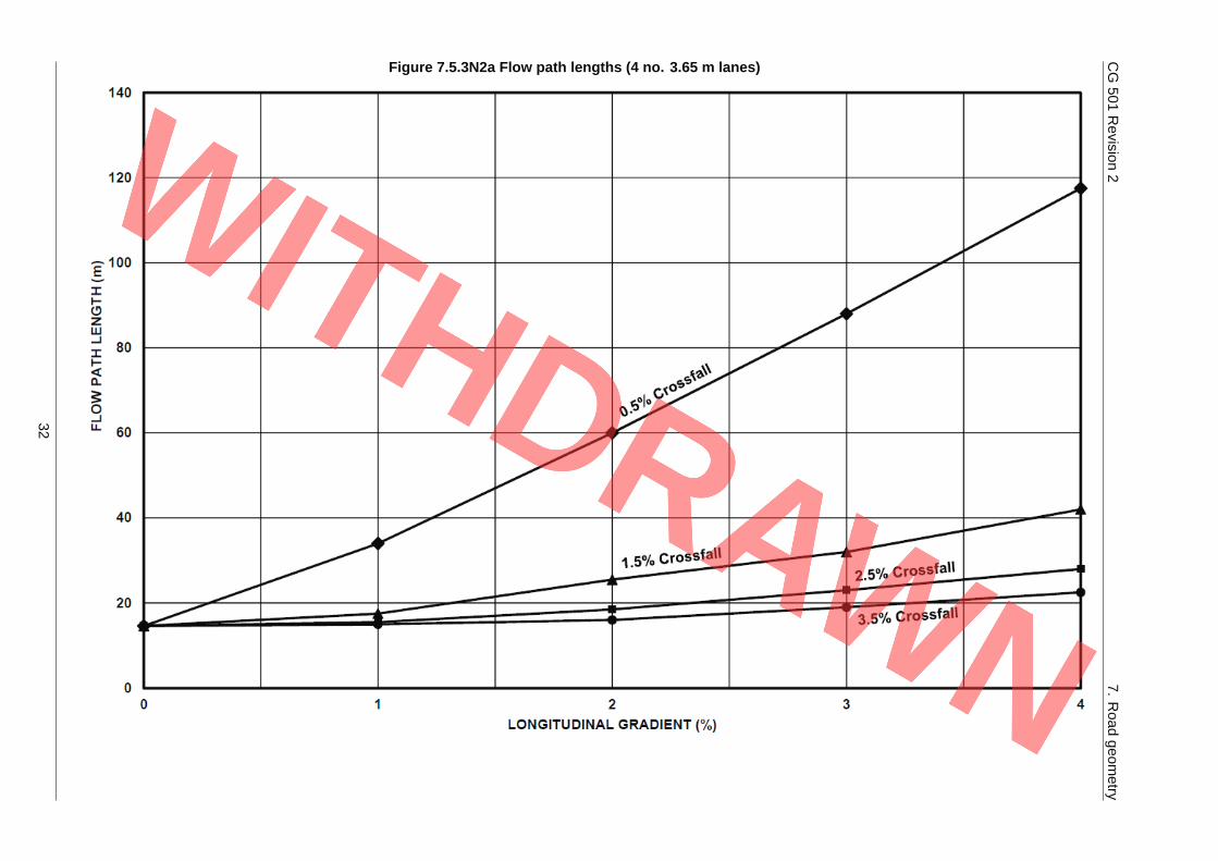
7.5.2 For lengths of carriageway with varying width and geometry, contoured plans of the carriagewaysurface should be generated in order to calculate local flow path lengths and gradients.
7.5.3 Flow path lengths and gradients may be checked by referring to Figures 7.5.3N2a and 7.5.3N2b.
NOTE 1 Flow path lengths can increase rapidly at low crossfalls.
NOTE 2 Roll-over lengths between superelevation are areas where low crossfalls occur and flow path lengthscan be long.
31
CG501
Revision
27.
Road
geometry
Figure 7.5.3N2a Flow path lengths (4 no. 3.65 m lanes)
32
CG501
Revision
27.
Road
geometry
Figure 7.5.3N2b Flow path gradients
33

CG 501 Revision 2 7. Road geometry
7.5.4 For lengths of carriageway with consistent geometry the combinations of localised flow path lengthsand gradients shown below the curve on Figure 7.5.4 should be avoided.
34

CG501
Revision
27.
Road
geometry
Figure 7.5.4 Effect of flow path length and flow path geometry on drainage
35

CG 501 Revision 2 7. Road geometry
Effect of carriageway edge markings
7.6 Continuous carriageway edge markings shall not exceed a thickness of 3 mm at the drainage exits tosuperelevation roll-over areas with sections having a crossfall less than 0.67 % (1 in 150).
NOTE 1 Carriageway surface drainage has the potential to be affected by continuous edge markings,particularly where raised rib markings are used.
NOTE 2 A continuous carriageway edge marking thickness of less than 3 mm allows water to drain over the lineduring storms.
7.7 Where the longitudinal gradient on any section of road is less than 0.67 % (1 in 150) 400 mm wide gapsshall be provided at 5 m centres in raised rib markings to minimise the risk of ice formation.
7.8 Where renewal of markings is being undertaken, existing lines shall be removed at the drainage exit toa superelevation roll-over area, where the longitudinal gradient is less than 0.67 % (1 in 150).
Crossfalls
7.9 Crossfalls shall be incorporated into the design to adequately drain water from the carriageway.
7.9.1 Where carriageway crown lines are used, crossfalls should be reduced from the standard 2.5 % (1 in40) to 2 % (1 in 50) for one lane width either side of the crown, to limit the change of angle to 4 % (1 in25).
NOTE 1 In CD 109 [Ref 8.I] guidance is given on how to assess both the drainage and appearance of the roadwhen applying superelevation.
NOTE 2 Crown lines are more easily introduced between hard shoulders and superelevated carriageways andat merges and diverges where lane gains and lane drops occur.
NOTE 3 Rolling crowns (crowns that run diagonally) can be applied where surface drainage cannot otherwisebe achieved.
7.9.2 Carriageway crossfalls may be increased from the standard 2.5 % (1 in 40) to 2.85 % (1 in 35) onlengths of carriageway that are straight or have radii well in excess of those requiring elimination ofadverse camber.
NOTE Applying an increased crossfall on the additional nearside lanes of a widened carriageway does notsignificantly reduce the depth of water at the edge of the carriageway but can increase the capacity ofthe road edge channel where kerbs are used.
36
CG 501 Revision 2 8. Pollution and flow control design
8. Pollution and flow control design
Principles of pollution and flow control8.1 Assessment of effects of road drainage on the water environment shall be carried out in accordance
with LA 113 [Ref 15.N].
8.2 LA 113 [Ref 15.N] shall be used to identify the need for pollution and flow control measures within adrainage design.
8.3 Pollution control measures shall be designed in compliance with LA 113 [Ref 15.N].
NOTE A number of the pollution control measures discussed within this document also provide a degree offlow control.
8.3.1 Pollution control measures should be designed to treat the 'first flush'.
NOTE Discharges from short intense storms with long antecedent dry periods pose a higher pollution threatthan discharges from longer rainfall events, which provide higher dilution.
8.3.2 A degree of bypass may be acceptable for the larger storm events, where runoff volumes can be higherand therefore there can be a greater degree of dilution.
NOTE Further information on design of pollution control measures in drainage is published in CIRIA C753 [Ref12.I] and the DMRB documents referenced in Table 8.6.4N3.
8.4 Where the design of pollution control measures includes infiltration into ground, the risk to groundwatershall be assessed and mitigation measures, where that assessment identifies the need, implemented inaccordance with LA 113 [Ref 15.N].
8.5 The design of pollution control measures shall include safe means of access for operation (whererelevant), emergency response and maintenance.
8.5.1 Pollution control measures should be located above the level of the flood plain wherever possible.
NOTE Storm water inundation can compromise the operation of pollution control devices.
Selection of pollution and flow control measures8.6 The selection and design of pollution and flow control measures shall follow the process presented
below:
1) complete assessment in accordance with LA 113 [Ref 15.N];
2) if mitigation is required, identify viable options/combinations of measures, taking account of:
a) road drainage hierarchy in this document;b) site constraints;c) storm flow and flood risk requirements;d) climate change allowances; ande) road geometry.
3) review short list of options against construction and maintenance requirements;
4) confirm measures fulfil mitigation requirements identified from LA 113 [Ref 15.N] assessment;
5) obtain approval for mitigation measures from Overseeing Organisation or relevant statutoryconsultation body; and
6) incorporate mitigation measures into overall drainage design.
8.6.1 Pollution control measures may be used to intercept pollution close to its source, treat it, managesediment mobilisation or reduce the risks from spillages.
NOTE 1 The selection and design of systems depends on the pollution load, the risk of spillage or flood and thesite conditions, particularly if protected habitats, species or sites can be affected.
37

CG 501 Revision 2 8. Pollution and flow control design
NOTE 2 Guidance on the design of pipelines for reduced sediment deposition is contained in CD 523 [Ref 5.N].
NOTE 3 Measures to control flooding generally include limiting (attenuating) peak outflows and providing anappropriate volume of water storage in the system to accommodate large or critical storm events.
8.6.2 Drainage designs for roads may include the following general categories of pollution control measures:
1) vegetated systems;
2) spillage control;
3) flow control; and
4) other pollution control mechanisms such as removal/separation of sediments or oils.
8.6.3 Where site conditions allow the use of vegetated systems their use should be prioritised over otherforms of treatment.
NOTE Further detail on the design of vegetated systems can be found in CD 532 [Ref 21.N].
8.6.4 Where verge space restricts the use of vegetated systems, the use of conventional drainage systems,either independently or in combination with vegetated systems should be reviewed.
NOTE 1 Table 8.6.4N3 presents potential treatment efficiencies for the various pollution control measure typesfor different contaminants.
NOTE 2 Types of treatment other than those listed in Table 8.6.4N3 are available.
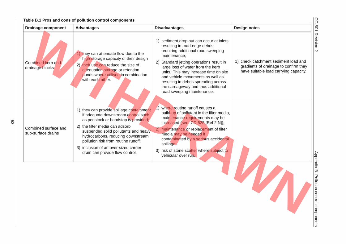
NOTE 3 The advantages and disadvantages of a selection of pollution control measures are presented inAppendix B.
38

CG501
Revision
28.
Pollution
andflow
controldesign
Table 8.6.4N3 Pollution and flow control measures options
Indicative treatment efficienciesCategory of measure
Name of measure Vegetatedsystems
Spillagecontrol
Flowcontrol
Otherpollutioncontrolmechanisms
Designstandardreferencedocuments
Suspendedsolids (%removal)
Dissolvedcopper (%removal)
Dissolvedzinc (%removal)
Optimumspillage riskreduction factorRF
Baffles Y Y 0 0 0
Combined kerb anddrainage blocks Y 0 0 0
Combined kerb andgully Y Y - sediment
removalX X X
Combined surfaceand sub-surfacedrains/filter drain
Y Y Y - pollutantremoval
CD 525 [Ref2.N] 60 0 45 0.6
Ditch (vegetated) Y Y - lined Y - lined/unlined
Y - sediment/pollutantremoval(unlined)
CD 532 [Ref21.N](vegetated) 25 15 15 0.7
Dry/detention basin Y Y Y - pollutantremoval
CD 532 [Ref21.N] 50 0 0 0.6
Infiltrationbasin/soakaway Y Y Y - pollutant
removal
CD 532 [Ref21.N] CD 530[Ref 3.I]
Infiltration of water facilitates theremoval of dissolved metals and solids.
0.6 (infiltrationbasin)
Notched weir Y Y 0 0 0 0.6
Penstock/valve Y Y 0 0 0 0.4
Piped systems Y 0 0 0
Ponds Y Y Y - pollutantremoval
CD 532 [Ref21.N] 60 40 30 0.5
Reservoirpavement/perviousasphalt
Y Y - sedimentremoval
CD 531 [Ref9.I] 50 0 0
Sedimentation tank Y Y - sedimentremoval
40 0 0
39

CG501
Revision
28.
Pollution
andflow
controldesign
Table 8.6.4N3 Pollution and flow control measures options (continued)
Indicative treatment efficienciesCategory of measure
Name of measure Vegetatedsystems
Spillagecontrol
Flowcontrol
Otherpollutioncontrolmechanisms
Designstandardreferencedocuments
Suspendedsolids (%removal)
Dissolvedcopper (%removal)
Dissolvedzinc (%removal)
Optimumspillage riskreduction factorRF
Sediment trap(catchpit)
Y - sedimentremoval
X X X 0.6
Surface waterchannel
YCD 521 [Ref10.N] X X X
Swale/grassedchannel
Y Y Y Y - pollutantremoval
CD 532 [Ref21.N] CD 521[Ref 10.N]
80 50 50 0.6
Vortex chamber Y 0 0 0
Vortex grit separator YY - sediment/pollutantremoval
CD 528 [Ref13.I] 40 0 15
Wetland (surfaceflow) Y Y Y - pollutant
removalCD 532 [Ref21.N] 60 30 50 0.5
40
CG 501 Revision 2 8. Pollution and flow control design
NOTE 4 Y - yes, X - removal of pollutants likely to occur but insufficient evidence available to quote indicativetreatment efficiency.
NOTE 5 Sedimentation tanks are not reliable for the removal of dissolved copper and zinc, nor vortex gritseparators for the removal of copper.
NOTE 6 A high proportion of highway pollutants are found to be adsorbed to the fine silt fraction of thesuspended solids. By collecting, filtering and treating the fine sediment which is subsequently removed,the system deals with a significant part of the runoff pollution.
NOTE 7 The spillage risk reduction factors in Table 8.6.4N3 represent what is considered achievable. Actualrisk reduction factors are site-specific and potentially higher (representing a lower risk reduction)depending on factors such as size of treatment system and retention time.
8.7 Oil separators shall not be used.
8.7.1 Existing oil separators should be replaced by an alternative solution for mitigating the potential impactsof road runoff.
NOTE 1 Oil separators are designed to mitigate oils and cannot be relied upon to treat suspended solids ordissolved metals.
NOTE 2 Oil separators require regular maintenance to function effectively.
Signage of pollution control devices8.8 Signs marking the location of pollution control devices are labelled as PCD (pollution control device)
and shall be designed in accordance with BS EN 12899-1 2007 [Ref 9.N].
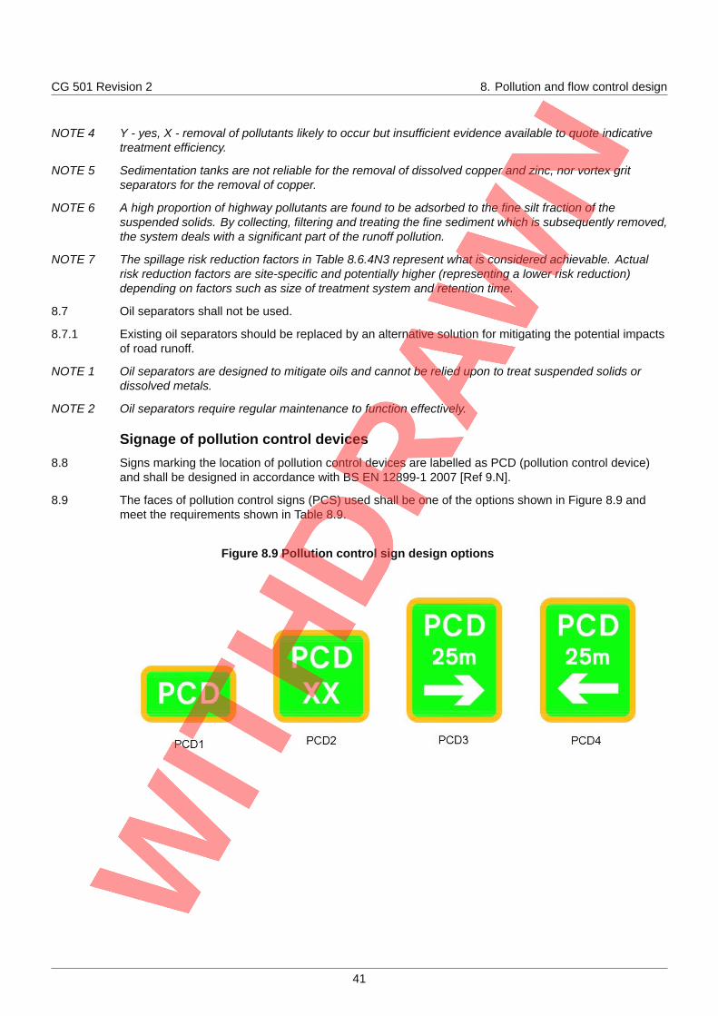
8.9 The faces of pollution control signs (PCS) used shall be one of the options shown in Figure 8.9 andmeet the requirements shown in Table 8.9.
Figure 8.9 Pollution control sign design options
41

CG 501 Revision 2 8. Pollution and flow control design
Table 8.9 Required attributes of pollution control signs
Attribute PCD1 PCD2 PCD3 PCD4
Legend white white white white
Background light green light green light green light green
Border yellow yellow yellow yellow
Font transportmedium
transportmedium
transportmedium
transportmedium
Material class 1 class 1 class 1 class 1
X-height (mm) 50 50 50 50
Width (mm) 320 320 320 320
Height (mm) 190 310 410 410
Area (m2) 0.06 0.1 0.13 0.13
NOTE 1 Class 1 - material that is retro-reflective Class 1 material in accordance with BS EN 1463 [Ref 16.N].
NOTE 2 Illumination of pollution control signs is not required.
8.10 The location of PCSs other than at the edge of the carriageway shall not be permitted without approvalof the Overseeing Organisation.
8.11 PCSs shall be visible from the running lanes of the carriageway.
8.11.1 The location of PCSs should be at least 600 mm from the edge of a single carriageway and 1500 mmfrom the edge of high-speed dual carriageway or motorway.
8.11.2 The mounting height of PCSs should be at least 900 mm above the highest point of the carriagewayimmediately adjacent to the sign.
8.11.3 The mounting height of PCSs may be increased up to 1500 mm where excessive spray is likely tooccur around the sign.
8.11.4 PCSs should specify the distance and direction to the device.
42
CG 501 Revision 2 9. Normative references
9. Normative referencesThe following documents, in whole or in part, are normative references for this document and areindispensable for its application. For dated references, only the edition cited applies. For undatedreferences, the latest edition of the referenced document (including any amendments) applies.
Ref 1.N Highways England. CD 127, 'Cross-sections and headrooms'
Ref 2.N Highways England. CD 525, 'Design of combined surface and sub-surface drains andmanagement of stone scatter'
Ref 3.N Highways England. CD 529, 'Design of outfall and culvert details'
Ref 4.N Highways England. CD 533, 'Determination of pipe and bedding combinations fordrainage works'
Ref 5.N Highways England. CD 523, 'Determination of pipe roughness and assessment ofsediment deposition to aid pipeline design'
Ref 6.N Highways England. CD 535, 'Drainage asset data and risk management'
Ref 7.N Highways England. CD 522, 'Drainage of runoff from natural catchments'
Ref 8.N Highways England. CD 524, 'Edge of pavement details'
Ref 9.N BSI. BS EN 12899-1, 'Fixed, vertical road traffic signs. Fixed signs' , 2007
Ref 10.N Highways England. CD 521, 'Hydraulic design of road edge surface water channelsand outlets'
Ref 11.N Highways England. GG 101, 'Introduction to the Design Manual for Roads andBridges'
Ref 12.N Highways England. MCHW, 'Manual of Contract Documents for Highway Works'
Ref 13.N Highways England. MCHW Series 500, 'Manual of Contract Documents for HighwayWorks, Volume 1 Specification for Highway Works. Series 500 Drainage and serviceducts.'
Ref 14.N Highways England. MCHW Series NG500, 'Manual of Contract Documents forHighway Works, Volume 2 Notes for Guidance on the Specification for HighwayWorks. - Drainage and Service Ducts'
Ref 15.N Highways England. LA 113, 'Road drainage and the water environment'
Ref 16.N BSI. BS EN 1463, 'Road marking materials. Retroreflecting road studs'
Ref 17.N Highways England. CD 526, 'Spacing of road gullies'
Ref 18.N Highways England. CG 502, 'The certification of drainage design'
Ref 19.N The National Archives. legislation .gov.uk. SI 2015/51, 'The Construction (Design andManagement) Regulations 2015'
Ref 20.N Department for Transport. DfT Circular 02/2013 , 'The strategic road network and thedelivery of sustainable development'
Ref 21.N Highways England. CD 532, 'Vegetated drainage systems for highway runoff'
43

CG 501 Revision 2 10. Informative references
10. Informative referencesThe following documents are informative references for this document and provide supportinginformation.
Ref 1.I Highways England. CD 534, 'Chamber tops and gully tops for road drainage andservices'
Ref 2.I Highways England. CD 225, 'Design for new pavement foundations'
Ref 3.I Highways England. CD 530, 'Design of soakaways'
Ref 4.I 2000/60/EC, 'Directive 2000/60/EC of the European Parliament and of the Council of23 October 2000 establishing a framework for Community action in the field of waterpolicy'
Ref 5.I SI 2016/1154, 'Environmental Permitting (England and Wales) Regulations 2016 (SI2016 No. 1154)'
Ref 6.I Construction Industry Research and Information Association. McBain W., Wilkes D.and Retter M.. CIRIA C688, 'Flood Resilience and Resistance for CriticalInfrastructure'
Ref 7.I Highways England. CD 116, 'Geometric design of roundabouts'
Ref 8.I Highways England. CD 109, 'Highway link design'
Ref 9.I Highways England. CD 531, 'Reservoir pavements for drainage attenuation'
Ref 10.I Highways England. CD 527, 'Sumpless gullies'
Ref 11.I Defra/Environment Agency. EA Groundwater protection, 'The Environment Agency'sapproach to groundwater protection'
Ref 12.I Construction Industry Research and Information Association. London.Woods-Ballard,B., Wilson,S., Udale Clark,H., Illman,S., Scott,T., Ashley,R.,Kellagher,R. CIRIA C753, 'The SuDS Manual'
Ref 13.I Highways England. CD 528, 'Vortex separators for use with road drainage systems'
44
CG 501 Revision 2 Appendix A. Drainage option advantages and disadvantages
Appendix A. Drainage option advantages and disadvantages
Table A.1 lists the types of drainage discussed in this document, and details potential advantages anddisadvantages of each drainage type.
45
CG501
Revision
2Appendix
A.D
rainageoption
advantagesand
disadvantages
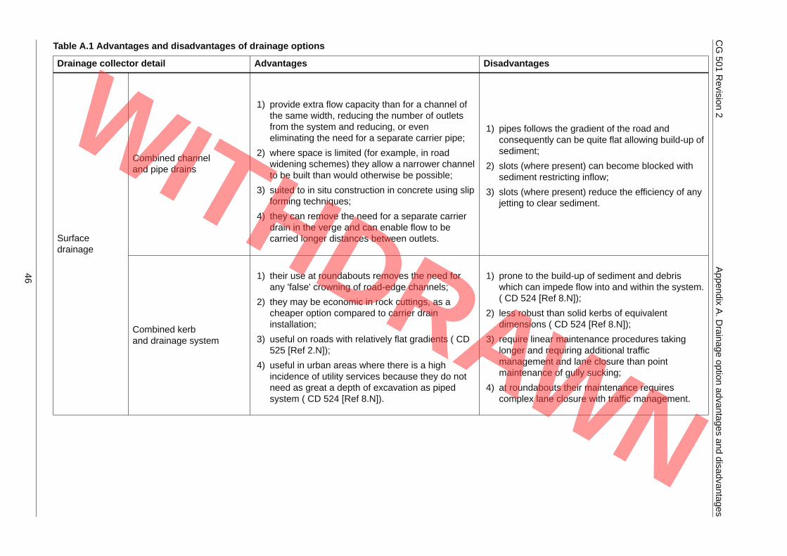
Table A.1 Advantages and disadvantages of drainage options
Drainage collector detail Advantages Disadvantages
Combined channeland pipe drains
1) provide extra flow capacity than for a channel ofthe same width, reducing the number of outletsfrom the system and reducing, or eveneliminating the need for a separate carrier pipe;
2) where space is limited (for example, in roadwidening schemes) they allow a narrower channelto be built than would otherwise be possible;
3) suited to in situ construction in concrete using slipforming techniques;
4) they can remove the need for a separate carrierdrain in the verge and can enable flow to becarried longer distances between outlets.
1) pipes follows the gradient of the road andconsequently can be quite flat allowing build-up ofsediment;
2) slots (where present) can become blocked withsediment restricting inflow;
3) slots (where present) reduce the efficiency of anyjetting to clear sediment.
Surfacedrainage
Combined kerband drainage system
1) their use at roundabouts removes the need forany 'false' crowning of road-edge channels;
2) they may be economic in rock cuttings, as acheaper option compared to carrier draininstallation;
3) useful on roads with relatively flat gradients ( CD525 [Ref 2.N]);
4) useful in urban areas where there is a highincidence of utility services because they do notneed as great a depth of excavation as pipedsystem ( CD 524 [Ref 8.N]).
1) prone to the build-up of sediment and debriswhich can impede flow into and within the system.( CD 524 [Ref 8.N]);
2) less robust than solid kerbs of equivalentdimensions ( CD 524 [Ref 8.N]);
3) require linear maintenance procedures takinglonger and requiring additional trafficmanagement and lane closure than pointmaintenance of gully sucking;
4) at roundabouts their maintenance requirescomplex lane closure with traffic management.
46
CG501
Revision
2Appendix
A.D
rainageoption
advantagesand
disadvantages
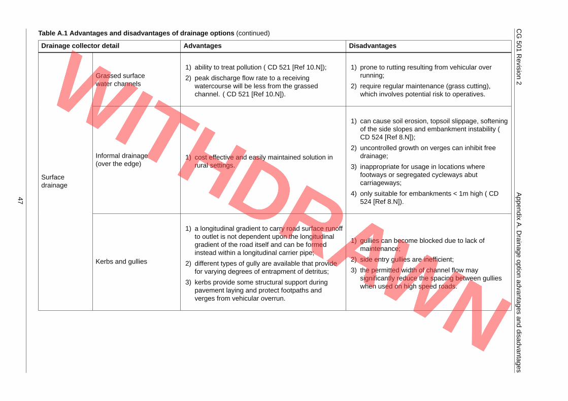
Table A.1 Advantages and disadvantages of drainage options (continued)
Drainage collector detail Advantages Disadvantages
Grassed surfacewater channels
1) ability to treat pollution ( CD 521 [Ref 10.N]);
2) peak discharge flow rate to a receivingwatercourse will be less from the grassedchannel. ( CD 521 [Ref 10.N]).
1) prone to rutting resulting from vehicular overrunning;
2) require regular maintenance (grass cutting),which involves potential risk to operatives.
Informal drainage(over the edge)
1) cost effective and easily maintained solution inrural settings.
1) can cause soil erosion, topsoil slippage, softeningof the side slopes and embankment instability (CD 524 [Ref 8.N]);
2) uncontrolled growth on verges can inhibit freedrainage;
3) inappropriate for usage in locations wherefootways or segregated cycleways abutcarriageways;
4) only suitable for embankments < 1m high ( CD524 [Ref 8.N]).
Surfacedrainage
Kerbs and gullies
1) a longitudinal gradient to carry road surface runoffto outlet is not dependent upon the longitudinalgradient of the road itself and can be formedinstead within a longitudinal carrier pipe;
2) different types of gully are available that providefor varying degrees of entrapment of detritus;
3) kerbs provide some structural support duringpavement laying and protect footpaths andverges from vehicular overrun.
1) gullies can become blocked due to lack ofmaintenance;
2) side entry gullies are inefficient;
3) the permitted width of channel flow maysignificantly reduce the spacing between gullieswhen used on high speed roads.
47

CG501
Revision
2Appendix
A.D
rainageoption
advantagesand
disadvantages
Table A.1 Advantages and disadvantages of drainage options (continued)
Drainage collector detail Advantages Disadvantages
Linear drainagechannels
1) may be used in both verges and central reserveson motorways ( CD 524 [Ref 8.N]).
1) linear drainage channels built on relatively flatgradients are prone to the build-up of sedimentand debris ( CD 524 [Ref 8.N]).
Surfacedrainage
Surface waterchannels
1) relatively easy maintenance;
2) long lengths can be constructed quickly and fairlyinexpensively;
3) it may be possible to locate channel outlets atappreciable spacings and possibly coincident withwatercourses;
4) the risk to vehicles and occupants impinging onsurface water channels is lower than for othertypes of surface drainage;
5) suited to in-situ construction in concrete using slipforming techniques (not blocks).
1) carriageways with flat longitudinal gradients maynecessitate discharge of channels fairly frequentlyinto outlets or parallel longitudinal carrier pipes inorder to minimise the size of the channels;
2) presence of features such as safety fences,services, lighting columns and signs may restrictability to use;
3) ability to install long channel lengths may beprevented by discontinuities in the verge/centralreserve such as piers, abutments, slip roads,junctions, laybys, central reserve crossoverpoints, emergency crossing points or changes insuperelevation.
48

CG501
Revision
2Appendix
A.D
rainageoption
advantagesand
disadvantages
Table A.1 Advantages and disadvantages of drainage options (continued)
Drainage collector detail Advantages Disadvantages
Surfacedrainage
Surface waterchannels with channelblocks
1) it may be possible to locate channel outlets atappreciable spacings and possibly coincident withwatercourses;
2) suited to use on steep embankments (Types D, Eand F) ( CD 524 [Ref 8.N]);
3) suitable where positive drainage is desirable fordealing with small volumes of flow that would notjustify use of the larger surface water channel.(Types A and B) () CD 524 [Ref 8.N].
1) effectiveness of drainage channel blocks isreduced by settlement of adjacent unpavedsurfaces;
2) drainage channel blocks are prone to the build-upof sediment and debris in flat areas;
3) presence of drainage channel blocks may reduceability to undertake mechanical grass cutting;
4) should be avoided in verges subject to frequentusage by equestrians or other vulnerable users;
5) presence of features such as safety fences,services, lighting columns and signs may restrictability to use;
6) ability to install long channel lengths may beprevented by discontinuities in the verge/centralreserve such as piers, abutments, slip roads,junctions, laybys, central reserve crossoverpoints, emergency crossing points or changes insuperelevation.
49
CG501
Revision
2Appendix
A.D
rainageoption
advantagesand
disadvantages
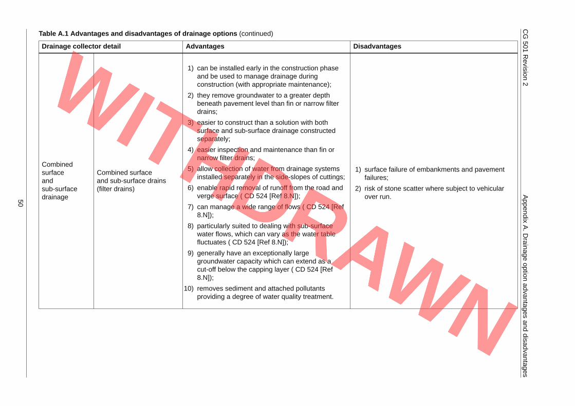
Table A.1 Advantages and disadvantages of drainage options (continued)
Drainage collector detail Advantages Disadvantages
Combinedsurfaceandsub-surfacedrainage
Combined surfaceand sub-surface drains(filter drains)
1) can be installed early in the construction phaseand be used to manage drainage duringconstruction (with appropriate maintenance);
2) they remove groundwater to a greater depthbeneath pavement level than fin or narrow filterdrains;
3) easier to construct than a solution with bothsurface and sub-surface drainage constructedseparately;
4) easier inspection and maintenance than fin ornarrow filter drains;
5) allow collection of water from drainage systemsinstalled separately in the side-slopes of cuttings;
6) enable rapid removal of runoff from the road andverge surface ( CD 524 [Ref 8.N]);
7) can manage a wide range of flows ( CD 524 [Ref8.N]);
8) particularly suited to dealing with sub-surfacewater flows, which can vary as the water tablefluctuates ( CD 524 [Ref 8.N]);
9) generally have an exceptionally largegroundwater capacity which can extend as acut-off below the capping layer ( CD 524 [Ref8.N]);
10) removes sediment and attached pollutantsproviding a degree of water quality treatment.
1) surface failure of embankments and pavementfailures;
2) risk of stone scatter where subject to vehicularover run.50
CG501
Revision
2Appendix
A.D
rainageoption
advantagesand
disadvantages
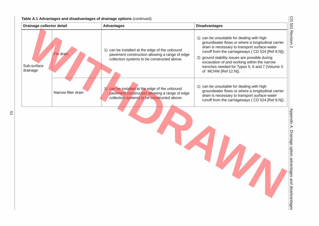
Table A.1 Advantages and disadvantages of drainage options (continued)
Drainage collector detail Advantages Disadvantages
Fin drain1) can be installed at the edge of the unbound
pavement construction allowing a range of edgecollection systems to be constructed above.
1) can be unsuitable for dealing with highgroundwater flows or where a longitudinal carrierdrain is necessary to transport surface-waterrunoff from the carriageways ( CD 524 [Ref 8.N]);
2) ground stability issues are possible duringexcavation of and working within the narrowtrenches needed for Types 5, 6 and 7 (Volume 3of MCHW [Ref 12.N]).
Sub-surfacedrainage
Narrow filter drain1) can be installed at the edge of the unbound
pavement construction allowing a range of edgecollection systems to be constructed above.
1) can be unsuitable for dealing with highgroundwater flows or where a longitudinal carrierdrain is necessary to transport surface-waterrunoff from the carriageways ( CD 524 [Ref 8.N]).
51

CG 501 Revision 2 Appendix B. Pollution control components
Appendix B. Pollution control components
52
CG501
Revision
2Appendix
B.P
ollutioncontrolcom
ponents
Table B.1 Pros and cons of pollution control components
Drainage component Advantages Disadvantages Design notes
Combined kerb anddrainage blocks
1) they can attenuate flow due to thehigh storage capacity of their design
2) their use can reduce the size ofattenuation storage or retentionponds where utilised in combinationwith each other.
1) sediment drop out can occur at inletsresulting in road-edge debrisrequiring additional road sweepingmaintenance;
2) Standard jetting operations result inlarge loss of water from the kerbunits. This may increase time on siteand vehicle movements as well asresulting in debris spreading acrossthe carriageway and thus additionalroad sweeping maintenance.
1) check catchment sediment load andgradients of drainage to confirm theyhave suitable load carrying capacity.
Combined surface andsub-surface drains
1) they can provide spillage containmentif adequate downstream control suchas penstock or handstop is provided;
2) the filter media can adsorbsuspended solid pollutants and heavyhydrocarbons, reducing downstreampollution risk from routine runoff;
3) inclusion of an over-sized carrierdrain can provide flow control.
1) where routine runoff causes abuild-up of pollutant in the filter media,maintenance requirements may beincreased (see CD 525 [Ref 2.N]);
2) maintenance or replacement of filtermedia may be needed ifcontaminated by a serious accidentalspillage;
3) risk of stone scatter where subject tovehicular over run.
53

CG501
Revision
2Appendix
B.P
ollutioncontrolcom
ponents
Table B.1 Pros and cons of pollution control components (continued)
Drainage component Advantages Disadvantages Design notes
Ditches
1) unlined ditches can allow infiltration ofrunoff through soil and vegetation,particularly where residence timesare long;
2) lined ditches can act as containmentbasins if located between the roaddrain and receiving watercourses.
1) scientifically robust information ontheir treatment performance is limited;
2) ditches with concrete or similar facingdo not have the same treatmentpotential as unlined ditches, but canbe adapted to contain spillages;
3) where unlined ditches are locatedabove permeable strata, there is arisk that highway runoff will infiltrateand potentially contaminate anyunderlying aquifer;
4) unlined ditches encourage vegetationgrowth that can hamper access andoperational ability as well asincreased maintenance requirement.
1) the direct input of a pollutant togroundwater without percolationthrough soil or subsoil is an offenceunder Section 12(1) of theEnvironmental Permitting RegulationsSI 2016/1154 [Ref 5.I];
2) ditches with shallow side slopes havesimilar properties to swales;
3) where lined ditches are used ascontainment basins they should havea minimum of 25 m3 capacity andhave a downstream control that canbe shut or blocked in the event ofaccidental spillage of pollutants onthe road.
Informal drainage (overthe edge)
1) they can provide, in somecircumstances, a degree of pollutioncontrol as highway runoff is allowed tofilter through vegetation on the slope;
2) pollution control is possible withinformal drainage, using adownstream control.
1) where informal drainage is usedabove permeable strata, there is arisk that highway runoff will infiltrateand potentially contaminate anyunderlying aquifer.
1) toe ditches associated with informaldrainage can be lined to preventpercolation through the soil or subsoil.
54

CG501
Revision
2Appendix
B.P
ollutioncontrolcom
ponents
Table B.1 Pros and cons of pollution control components (continued)
Drainage component Advantages Disadvantages Design notes
Kerbs and gullies
1) ability to capture potentiallycontaminated sediments duringnormal rainfall events prior todischarge into a receivingwatercourse;
2) provide initial stage of interception ofspillages.
1) less effective at trapping finer grainedsediment than coarser grainedsediment;
2) high inflow rates can causere-suspension of sediments andmixing of oils with the water in thegully pot;
3) contaminated water can dischargefrom the gully pot into the receivingdrainage network or watercourse.
1) re-suspension or mixing of oils can beavoided by ensuring that the gradientof the pipe leading to the gully is asshallow as possible whilst stillproviding adequate hydraulicperformance;
2) sumpless gullies should beconsidered where this is not possible.
Penstocks andhandstops
1) they can provide spillage containmentif they are closed in time.
1) failure to open penstock after spillageincident (or closure of penstock dueto vandalism or equipment failure etc)could result in flooding or scouringfollowing breach of the headwall orditch;
2) regular maintenance needed;
3) handstops not appropriate for largersystems.
1) the size of handstops should be suchthat the plate can be lifted manually.
Piped systems1) they can provide spillage containment
if adequate downstream control suchas penstock or handstop is provided.
55
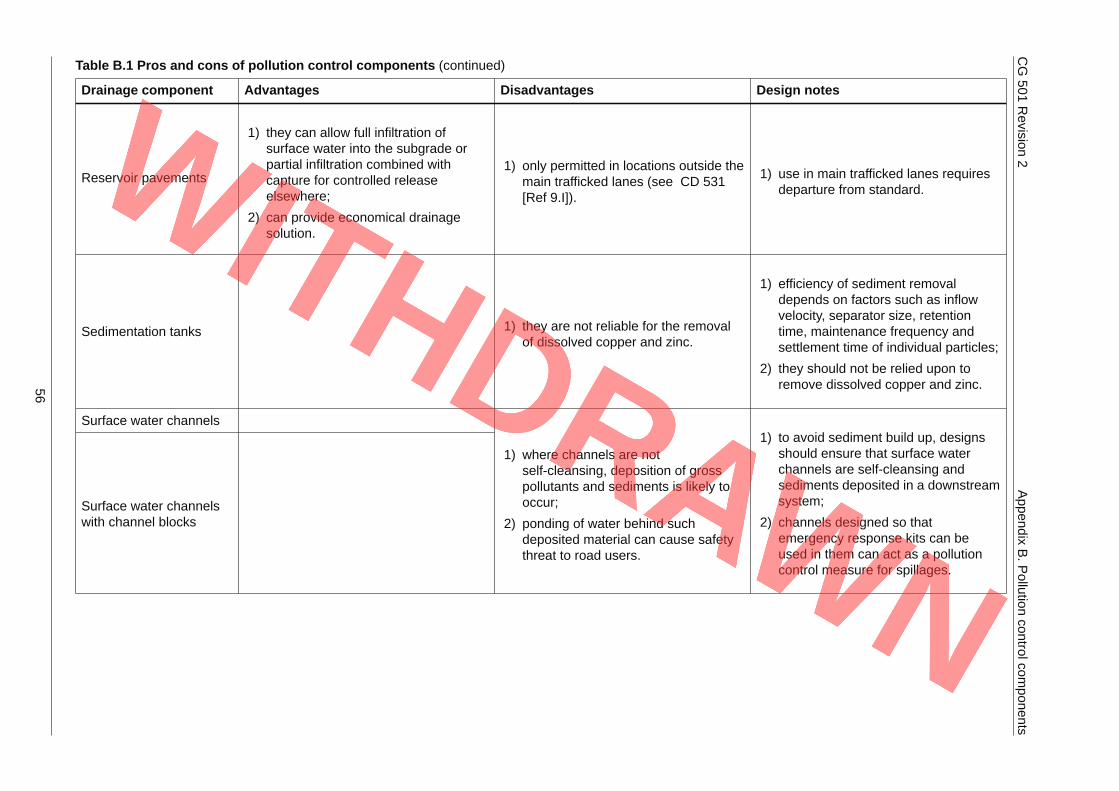
CG501
Revision
2Appendix
B.P
ollutioncontrolcom
ponents
Table B.1 Pros and cons of pollution control components (continued)
Drainage component Advantages Disadvantages Design notes
Reservoir pavements
1) they can allow full infiltration ofsurface water into the subgrade orpartial infiltration combined withcapture for controlled releaseelsewhere;
2) can provide economical drainagesolution.
1) only permitted in locations outside themain trafficked lanes (see CD 531[Ref 9.I]).
1) use in main trafficked lanes requiresdeparture from standard.
Sedimentation tanks 1) they are not reliable for the removalof dissolved copper and zinc.
1) efficiency of sediment removaldepends on factors such as inflowvelocity, separator size, retentiontime, maintenance frequency andsettlement time of individual particles;
2) they should not be relied upon toremove dissolved copper and zinc.
Surface water channels
Surface water channelswith channel blocks
1) where channels are notself-cleansing, deposition of grosspollutants and sediments is likely tooccur;
2) ponding of water behind suchdeposited material can cause safetythreat to road users.
1) to avoid sediment build up, designsshould ensure that surface waterchannels are self-cleansing andsediments deposited in a downstreamsystem;
2) channels designed so thatemergency response kits can beused in them can act as a pollutioncontrol measure for spillages.
56
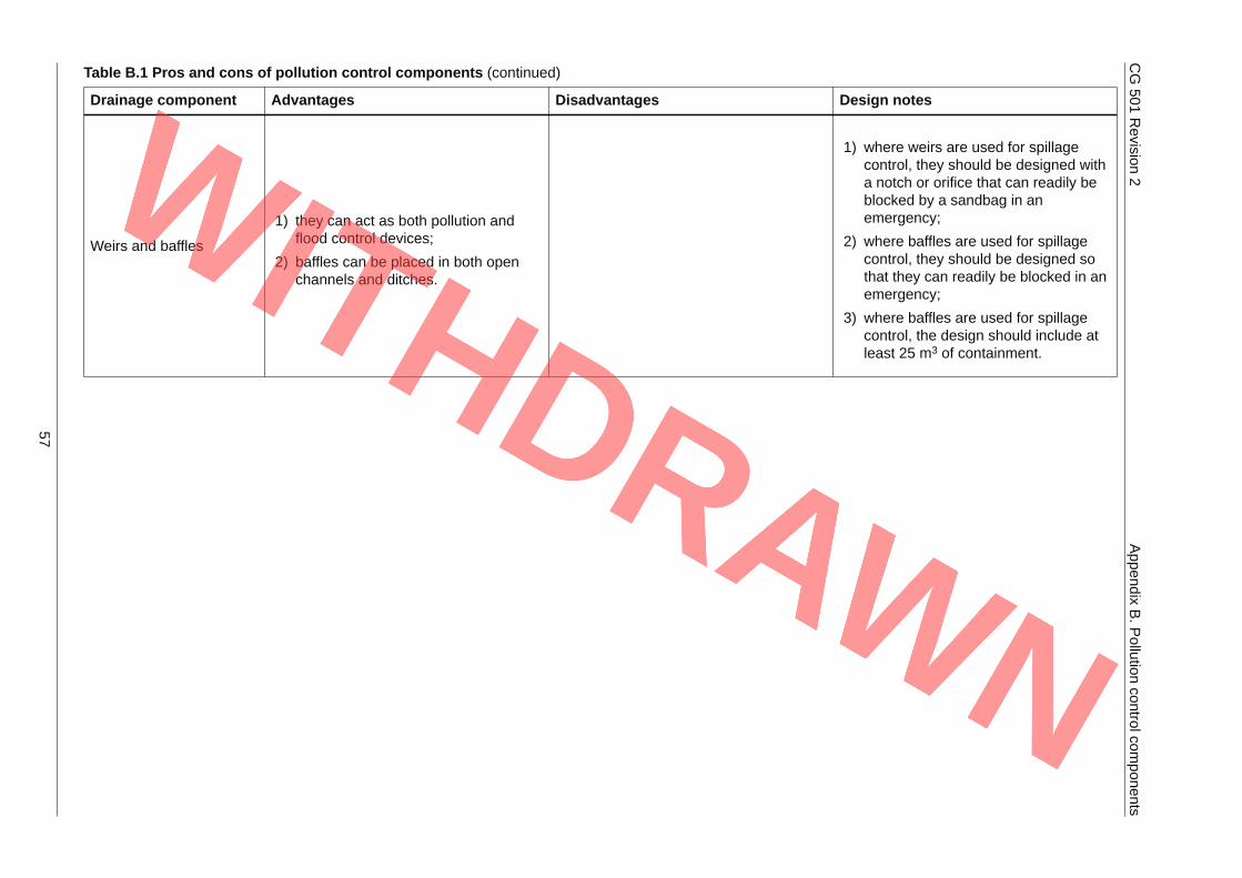
CG501
Revision
2Appendix
B.P
ollutioncontrolcom
ponents
Table B.1 Pros and cons of pollution control components (continued)
Drainage component Advantages Disadvantages Design notes
Weirs and baffles
1) they can act as both pollution andflood control devices;
2) baffles can be placed in both openchannels and ditches.
1) where weirs are used for spillagecontrol, they should be designed witha notch or orifice that can readily beblocked by a sandbag in anemergency;
2) where baffles are used for spillagecontrol, they should be designed sothat they can readily be blocked in anemergency;
3) where baffles are used for spillagecontrol, the design should include atleast 25 m3 of containment.
57
© Crown copyright 2020.You may re-use this information (not including logos) free of charge in any format or medium, under the terms of the
Open Government Licence. To view this licence:visit www.nationalarchives.gov.uk/doc/open-government-licence/,
write to the Information Policy Team, The National Archives, Kew, London TW9 4DU,or email [email protected].
Related Documents