CFRP-Based Strengthening Technique to Increase the Flexural and Energy Dissipation Capacities of RC Columns Monia Perrone 1 ; Joaquim A. O. Barros 2 ; and Alessandra Aprile 3 Abstract: A strengthening technique, combining carbon fiber-reinforced polymer CFRP laminates and strips of wet layup CFRP sheet, is used to increase both the flexural and the energy dissipation capacities of reinforced concrete RC columns of square cross section of low to moderate concrete strength class, subjected to constant axial compressive load and increasing lateral cyclic loading. The laminates were applied according to the near surface mounted technique to increase the flexural resistance of the columns, while the strips of CFRP sheet were installed according to the externally bonded reinforcement technique to enhance the concrete confinement, particularly in the plastic hinge zone where they also offer resistance to the buckling and debonding of the laminates and longitudinal steel bars. The performance of this strengthening technique is assessed in undamaged RC columns and in columns that were subjected to intense damage. The influence of the concrete strength and percentage of longitudinal steel bars on the strengthening effectiveness is assessed. In the groups of RC columns of 8 MPa concrete compressive strength, this technique provided an increase of about 67% and 46% in terms of column’s load carrying capacity, when applied to undamaged and damaged columns, respectively. In terms of energy dissipation capacity, the increase ranged from 40%–87% in the undamaged columns, while a significant increase of about 39% was only observed in one of the damaged columns. In the column of moderate concrete compressive strength 29 MPa, the technique was even much more effective, since, when compared to the maximum load and energy dissipation capacity of the corresponding strengthened column of 8 MPa of average compressive strength, it provided an increase of 39% and 109%, respectively, showing its appropriateness for RC columns of buildings requiring upgrading against seismic events. DOI: 10.1061/ASCECC.1943-5614.0000031 CE Database subject headings: Fiber reinforced polymers; Flexural resistance; Confinement; Cyclic load; Energy dissipation. Introduction Fiber-reinforced polymer FRP materials are used to strengthen existing reinforced concrete RC structures requiring mainte- nance due to problems of deficient design and/or construction practices, space, functionality or loading alterations, and seismic upgrading. The endurance of a RC structure is very dependent on the resistance and energy dissipation capacity of its columns. Therefore, the development of competitive and effective strength- ening techniques that provide significant increase in terms of load carrying and energy dissipation capacities to RC columns is of paramount importance for a sound retrofitting of the built patri- mony. Furthermore, the technique should avoid the occurrence of shear brittle failure modes and offer resistance to the debonding of the starter steel bars in the lap splice zones and to the buckling of the longitudinal bars in compression. Externally bonded rein- forcement EBR and near-surface mounted NSM reinforcement are the main FRP-based strengthening techniques used on the rehabilitation of RC structures. In the case of columns, the EBR technique is used to increase the concrete confinement and the column shear resistance, as well as to avoid buckling of longitu- dinal steel bars and to enhance the bond behavior of the starter bars in the lap splice zones Saadatmanesh et al. 1994, 1996, 1997; Lin and Liao 2004; Berthet et al. 2005; Yalcin et al. 2008. The available experimental research shows that for equal per- centage of FRP confinement material, full wrapping of the con- crete column provides higher load carrying and energy absorption capacities than discrete confinement arrangements. However, tak- ing into account are that existing steel hoops assure certain con- crete confinement, the effectiveness of discrete confinement arrangements, consisting on applying strips of FRP wet layup sheets in between existing steel hoops, can still be significant in terms of load carrying and energy dissipation requirements, and in terms of economy of FRP materials Barros and Ferreira 2008. The NSM technique is based on installing laminates into precut grooves executed on the concrete cover of the elements to strength, and has been used to increase the flexural strength of beams El-Hacha and Rizkalla 2004; Barros and Fortes 2005; De Lorenzis and Teng 2007; Carolin 2003; Jung et al. 2005; Kotynia 2005 and slabs Bonaldo et al. 2008. For columns, NSM proved to be very effective in terms of increasing their flexural resistance, as long as the NSM bars can be effectively anchored in the adjacent elements Barros et al. 2006; Bournas and Triantafillou 2008. The NSM technique is, however, not ef- fective in terms of enhancing the energy dissipation capacity of RC columns. Therefore, combining NSM laminates for the flex- ural resistance, with strips of wet layup FRP sheets located in 1 Researcher, Dept. of Engineering, Univ. of Ferrara, Via Saragat 1-44100, Ferrara, Italy. E-mail: [email protected] 2 Associate Professor, Dept. of Civil Engineering, Univ. of Minho, Azurém 4800-058, Guimarães, Portugal corresponding author. E-mail: [email protected] 3 Assistant Professor, Dept. of Engineering, Univ. of Ferrara, Via Saragat 1-44100, Ferrara, Italy. E-mail: [email protected] Note. This manuscript was submitted on September 29, 2008; ap- proved on February 12, 2009; published online on March 6, 2009. Dis- cussion period open until March 1, 2010; separate discussions must be submitted for individual papers. This paper is part of the Journal of Composites for Construction, Vol. 13, No. 5, October 1, 2009. ©ASCE, ISSN 1090-0268/2009/5-372–383/$25.00. 372 / JOURNAL OF COMPOSITES FOR CONSTRUCTION © ASCE / SEPTEMBER/OCTOBER 2009 Downloaded 12 Jul 2011 to 137.204.62.232. Redistribution subject to ASCE license or copyright. Visit http://www.ascelibrary.org

Welcome message from author
This document is posted to help you gain knowledge. Please leave a comment to let me know what you think about it! Share it to your friends and learn new things together.
Transcript
CFRP-Based Strengthening Technique to Increase theFlexural and Energy Dissipation Capacities of RC Columns
Monia Perrone1; Joaquim A. O. Barros2; and Alessandra Aprile3
Abstract: A strengthening technique, combining carbon fiber-reinforced polymer �CFRP� laminates and strips of wet layup CFRP sheet,is used to increase both the flexural and the energy dissipation capacities of reinforced concrete �RC� columns of square cross section oflow to moderate concrete strength class, subjected to constant axial compressive load and increasing lateral cyclic loading. The laminateswere applied according to the near surface mounted technique to increase the flexural resistance of the columns, while the strips of CFRPsheet were installed according to the externally bonded reinforcement technique to enhance the concrete confinement, particularly in theplastic hinge zone where they also offer resistance to the buckling and debonding of the laminates and longitudinal steel bars. Theperformance of this strengthening technique is assessed in undamaged RC columns and in columns that were subjected to intense damage.The influence of the concrete strength and percentage of longitudinal steel bars on the strengthening effectiveness is assessed. In thegroups of RC columns of 8 MPa concrete compressive strength, this technique provided an increase of about 67% and 46% in terms ofcolumn’s load carrying capacity, when applied to undamaged and damaged columns, respectively. In terms of energy dissipation capacity,the increase ranged from 40%–87% in the undamaged columns, while a significant increase of about 39% was only observed in one ofthe damaged columns. In the column of moderate concrete compressive strength �29 MPa�, the technique was even much more effective,since, when compared to the maximum load and energy dissipation capacity of the corresponding strengthened column of 8 MPa ofaverage compressive strength, it provided an increase of 39% and 109%, respectively, showing its appropriateness for RC columns ofbuildings requiring upgrading against seismic events.
DOI: 10.1061/�ASCE�CC.1943-5614.0000031
CE Database subject headings: Fiber reinforced polymers; Flexural resistance; Confinement; Cyclic load; Energy dissipation.
Introduction
Fiber-reinforced polymer �FRP� materials are used to strengthenexisting reinforced concrete �RC� structures requiring mainte-nance due to problems of deficient design and/or constructionpractices, space, functionality or loading alterations, and seismicupgrading. The endurance of a RC structure is very dependent onthe resistance and energy dissipation capacity of its columns.Therefore, the development of competitive and effective strength-ening techniques that provide significant increase in terms of loadcarrying and energy dissipation capacities to RC columns is ofparamount importance for a sound retrofitting of the built patri-mony. Furthermore, the technique should avoid the occurrence ofshear brittle failure modes and offer resistance to the debondingof the starter steel bars in the lap splice zones and to the bucklingof the longitudinal bars in compression. Externally bonded rein-forcement �EBR� and near-surface mounted �NSM� reinforcement
1Researcher, Dept. of Engineering, Univ. of Ferrara, Via Saragat1-44100, Ferrara, Italy. E-mail: [email protected]
2Associate Professor, Dept. of Civil Engineering, Univ. of Minho,Azurém 4800-058, Guimarães, Portugal �corresponding author�. E-mail:[email protected]
3Assistant Professor, Dept. of Engineering, Univ. of Ferrara, ViaSaragat 1-44100, Ferrara, Italy. E-mail: [email protected]
Note. This manuscript was submitted on September 29, 2008; ap-proved on February 12, 2009; published online on March 6, 2009. Dis-cussion period open until March 1, 2010; separate discussions must besubmitted for individual papers. This paper is part of the Journal ofComposites for Construction, Vol. 13, No. 5, October 1, 2009. ©ASCE,
ISSN 1090-0268/2009/5-372–383/$25.00.372 / JOURNAL OF COMPOSITES FOR CONSTRUCTION © ASCE / SEPTE
Downloaded 12 Jul 2011 to 137.204.62.232. Redistribu
are the main FRP-based strengthening techniques used on therehabilitation of RC structures. In the case of columns, the EBRtechnique is used to increase the concrete confinement and thecolumn shear resistance, as well as to avoid buckling of longitu-dinal steel bars and to enhance the bond behavior of the starterbars in the lap splice zones �Saadatmanesh et al. 1994, 1996,1997; Lin and Liao 2004; Berthet et al. 2005; Yalcin et al. 2008�.The available experimental research shows that for equal per-centage of FRP confinement material, full wrapping of the con-crete column provides higher load carrying and energy absorptioncapacities than discrete confinement arrangements. However, tak-ing into account are that existing steel hoops assure certain con-crete confinement, the effectiveness of discrete confinementarrangements, consisting on applying strips of FRP wet layupsheets in between existing steel hoops, can still be significant interms of load carrying and energy dissipation requirements, and interms of economy of FRP materials �Barros and Ferreira 2008�.The NSM technique is based on installing laminates into precutgrooves executed on the concrete cover of the elements tostrength, and has been used to increase the flexural strength ofbeams �El-Hacha and Rizkalla 2004; Barros and Fortes 2005;De Lorenzis and Teng 2007; Carolin 2003; Jung et al. 2005;Kotynia 2005� and slabs �Bonaldo et al. 2008�. For columns,NSM proved to be very effective in terms of increasing theirflexural resistance, as long as the NSM bars can be effectivelyanchored in the adjacent elements �Barros et al. 2006; Bournasand Triantafillou 2008�. The NSM technique is, however, not ef-fective in terms of enhancing the energy dissipation capacity ofRC columns. Therefore, combining NSM laminates for the flex-
ural resistance, with strips of wet layup FRP sheets located inMBER/OCTOBER 2009
tion subject to ASCE license or copyright. Visithttp://www.ascelibrary.org
between existing steel hoops, a high effective technique can beobtained, which is herein designated as hybrid FRP-basedstrengthening technique. The present work is dedicated to theassessment of the effectiveness of this hybrid strengthening tech-nique in terms of load carrying and energy dissipation capacities,when applied to square cross section RC columns of low andmoderate concrete strength classes. The test program, consistingof eight column prototypes subjected to constant axial compres-sive load and increasing lateral cyclic loading, was conceived toassess the influence on the effectiveness of this technique of theconcrete compressive strength, longitudinal steel reinforcementratio and number of layers of wet layup carbon-FRP �CFRP�sheet. The experimental program is described in detail and themost important results are presented and discussed.
Specimens and Test Series
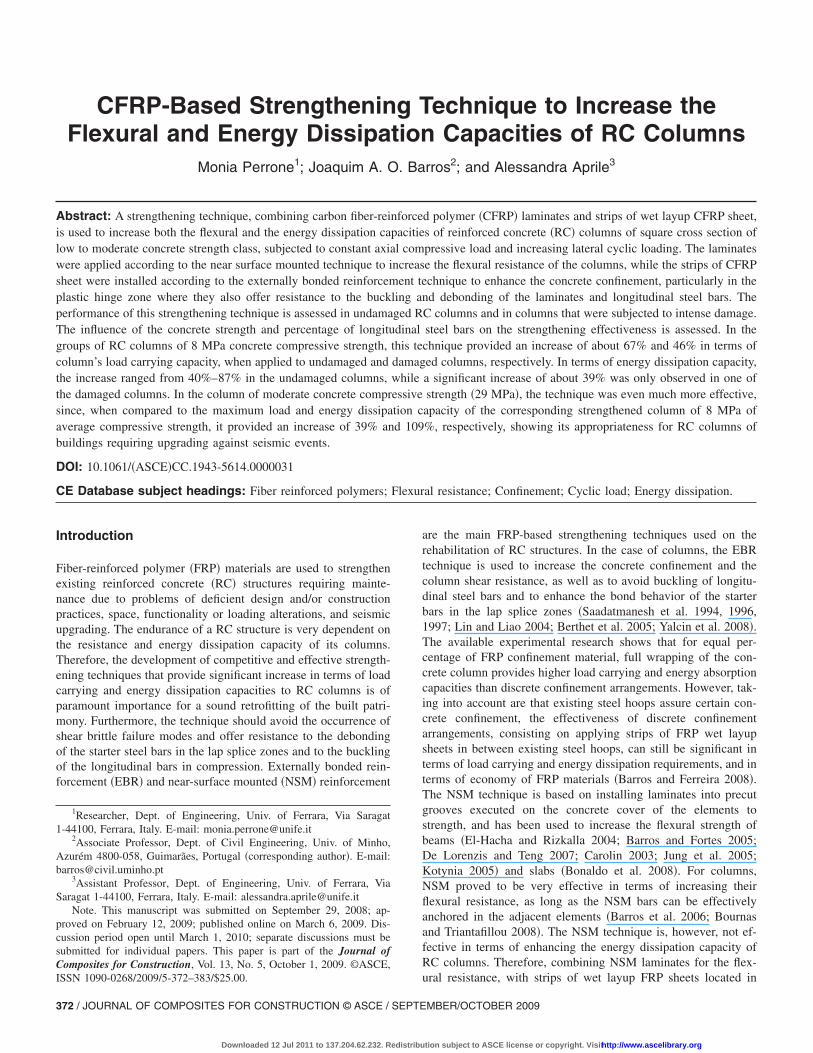
Fig. 1 shows the typical specimen of the experimental program,which is composed of a RC column monolithically connected to aRC footing. The column was cast in a second phase, three daysafter the corresponding footing has been cast, to reproduce thereal practice as much as possible. With the same purpose, starterlongitudinal steel bars were used to connect the reinforcementsystem of the column to the corresponding foot �see Fig. 1�a��.The lap splice of the starter bars had a length of 260 mm �CEB-FIP 1993�. The research program had the purpose of evaluatingthe influence of the concrete compressive strength, reinforcementratio of longitudinal steel bars ��sl�, and number of CFRP layersper each strip, on the load carrying and energy dissipation capaci-ties of RC columns strengthened according to the hybrid tech-nique. The full experimental program is described in Table 1. Thefirst eight columns were built with 8 MPa concrete compressivestrengths, while the last column had a compressive strength of 29MPa. The arrangement of the CFRP strips of wet layup sheets is
2F(10,12,16)L=800mm
200360
1300 (x1300)25AA
10250
250
1500
250
250
250
250
# 7F16
190190130152 145 130 152145
260
260
65
Φ6@50 mm
Φ6@250 mm
2F(10,12,16)L=1500mm
# 7F16
200
2F (10, 12, 16)
250
250
25
25
210
Stirrups F6/250mm L=1000 mm
210
a)
Fig. 1. Geometry of the columns, steel reinforcement arrangeme
represented in Fig. 1�b�. The identification of the columns has the
JOURNAL OF COMPOSITES F
Downloaded 12 Jul 2011 to 137.204.62.232. Redistribu
format Fa_Sb_Lc_t, where “a” represents the diameter of thelongitudinal steel bars, in mm �10, 12, or 16�, “b” is the numberof CFRP laminates applied in each face of the column subjectedto cyclic tension/compression, to increase the column flexural re-sistance �2, 3, and 4–see Fig. 2�, “c” represents the number ofCFRP layers in each strip �2 and 3� and “t” is the type of series�NON, PRE, and POS�. The NON term means a reference col-umn, PRE is a column that was strengthened before having beentested and POS means a column that, after having been tested andstrengthened, it was again tested.
Strengthening Technique
The strengthening technique is composed by CFRP laminates of9.37�1.4 mm2 of cross section area �CFK 150/2000 by S&P�,fixed to concrete by epoxy adhesive �Resin 220 by S&P� intoprecut slits opened on the concrete cover of faces of the columnthat will be subjected to cyclic compression/tension stresses
Table 1. Groups of Tests
Group n Designation Specimen reference
1 G1 F10_NON
F12_NON
F16_NON
F10_S2_L2_POS
F12_S3_L2_POS
F16_S4_L2_POS
2 G2 F10_S2_L2_PRE
F12_S3_L2_PRE
F16_S4_L2_PRE
3 G3 F12_S3_L3_PRE
4 G4 F12_S3_L2_PRE_C25/30
200 200
360
25
AA
10
150
150
250
250
1500
250
250
250
250
400110
150
100
150
100
250
260
260
2F(1
0,12,16)
L=1500
mm
2F(1
0,12,16)
L=1500
mm
2F(10,12,16)L=800mm
2F( 1
0,12,16)
L=800mm
1300 (x1300)190190130 145 130 152145
430
152
b)
d disposition of the CFRP wet layup strips �dimensions in mm�
2F(10,12,16)L=800mm2F(10,12,16)L=1500mm
nt, an
OR CONSTRUCTION © ASCE / SEPTEMBER/OCTOBER 2009 / 373
tion subject to ASCE license or copyright. Visithttp://www.ascelibrary.org
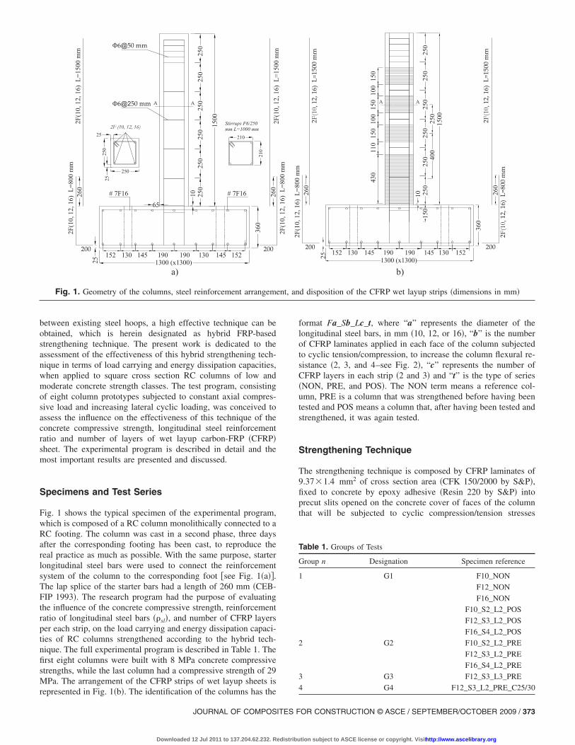
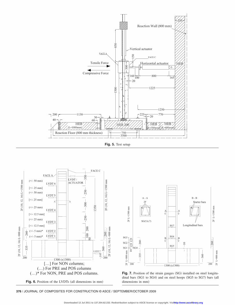
�faces A and C in Fig. 5� and strips of CFRP wet layup sheet. Thefirst strip was applied at the bottom of the column, with a widthof 430 mm that is similar to the pre-evaluated length of the plas-tic hinge �Perrone 2008�, and the remaining strips, of a widthof 150 mm, were applied in between the existing steel hoops �seeFig. 1�b��. Fig. 2 shows the positions of the laminates forthe columns reinforced with distinct percentage of longitudinalsteel bars. The number of CFRP laminates was evaluated to pro-vide an increase of 50% in the load carrying capacity of its cor-
250
DETAIL "A"
250
R202 CFRP laminates
25
17.517517.5
4 bars F10
250
250
3 CFRP laminates
25
8817.5 17.5
4 bars F12
88
Fig. 2. Arrangement of the steel reinforcement and CFRP l
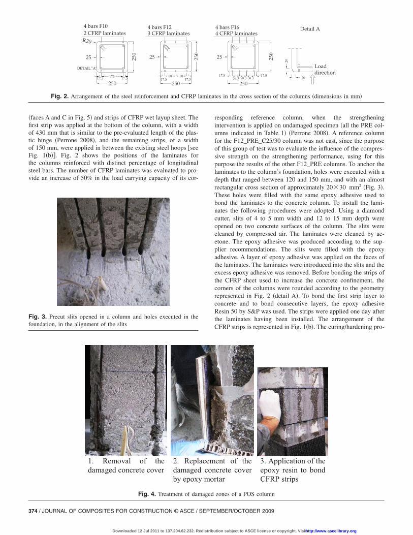
Fig. 3. Precut slits opened in a column and holes executed in thefoundation, in the alignment of the slits
1. Removal of thedamaged concrete cover
2. Repldamagedby epoxy
Fig. 4. Treatment of dam
374 / JOURNAL OF COMPOSITES FOR CONSTRUCTION © ASCE / SEPTE
Downloaded 12 Jul 2011 to 137.204.62.232. Redistribu
responding reference column, when the strengtheningintervention is applied on undamaged specimen �all the PRE col-umns indicated in Table 1� �Perrone 2008�. A reference columnfor the F12_PRE_C25/30 column was not cast, since the purposeof this group of test was to evaluate the influence of the compres-sive strength on the strengthening performance, using for thispurpose the results of the other F12_PRE columns. To anchor thelaminates to the column’s foundation, holes were executed with adepth that ranged between 120 and 150 mm, and with an almostrectangular cross section of approximately 20�30 mm2 �Fig. 3�.These holes were filled with the same epoxy adhesive used tobond the laminates to the concrete column. To install the lami-nates the following procedures were adopted. Using a diamondcutter, slits of 4 to 5 mm width and 12 to 15 mm depth wereopened on two concrete surfaces of the column. The slits werecleaned by compressed air. The laminates were cleaned by ac-etone. The epoxy adhesive was produced according to the sup-plier recommendations. The slits were filled with the epoxyadhesive. A layer of epoxy adhesive was applied on the faces ofthe laminates. The laminates were introduced into the slits and theexcess epoxy adhesive was removed. Before bonding the strips ofthe CFRP sheet used to increase the concrete confinement, thecorners of the columns were rounded according to the geometryrepresented in Fig. 2 �detail A�. To bond the first strip layer toconcrete and to bond consecutive layers, the epoxy adhesiveResin 50 by S&P was used. The strips were applied one day afterthe laminates having been installed. The arrangement of theCFRP strips is represented in Fig. 1�b�. The curing/hardening pro-
250
25025
17.5 17.558.3 58.358.3 20
20
Detail A4 CFRP laminates4 bars F16
Loaddirection
tes in the cross section of the columns �dimensions in mm�
ent of thecrete covertar
3. Application of theepoxy resin to bondCFRP strips
zones of a POS column
amina
acemconmor
aged
MBER/OCTOBER 2009
tion subject to ASCE license or copyright. Visithttp://www.ascelibrary.org
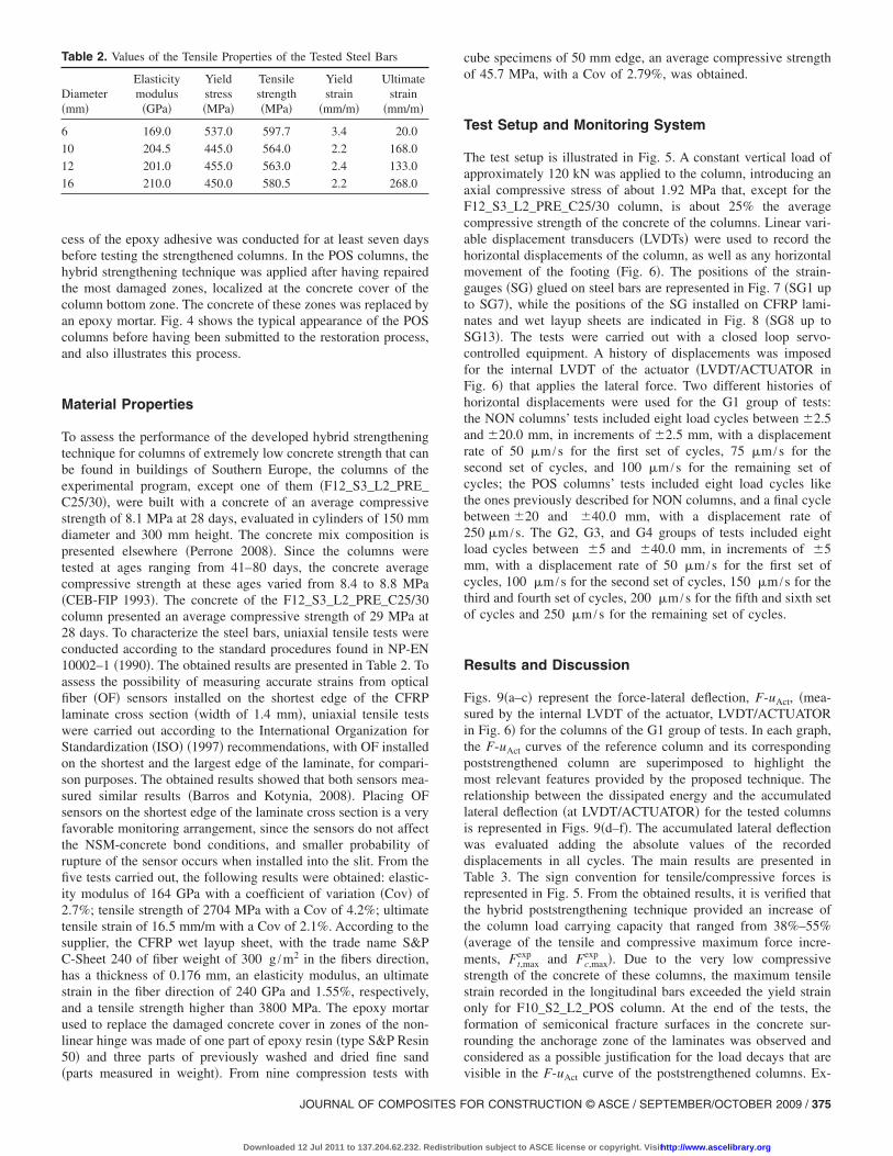
cess of the epoxy adhesive was conducted for at least seven daysbefore testing the strengthened columns. In the POS columns, thehybrid strengthening technique was applied after having repairedthe most damaged zones, localized at the concrete cover of thecolumn bottom zone. The concrete of these zones was replaced byan epoxy mortar. Fig. 4 shows the typical appearance of the POScolumns before having been submitted to the restoration process,and also illustrates this process.
Material Properties
To assess the performance of the developed hybrid strengtheningtechnique for columns of extremely low concrete strength that canbe found in buildings of Southern Europe, the columns of theexperimental program, except one of them �F12_S3_L2_PRE_C25/30�, were built with a concrete of an average compressivestrength of 8.1 MPa at 28 days, evaluated in cylinders of 150 mmdiameter and 300 mm height. The concrete mix composition ispresented elsewhere �Perrone 2008�. Since the columns weretested at ages ranging from 41–80 days, the concrete averagecompressive strength at these ages varied from 8.4 to 8.8 MPa�CEB-FIP 1993�. The concrete of the F12_S3_L2_PRE_C25/30column presented an average compressive strength of 29 MPa at28 days. To characterize the steel bars, uniaxial tensile tests wereconducted according to the standard procedures found in NP-EN10002–1 �1990�. The obtained results are presented in Table 2. Toassess the possibility of measuring accurate strains from opticalfiber �OF� sensors installed on the shortest edge of the CFRPlaminate cross section �width of 1.4 mm�, uniaxial tensile testswere carried out according to the International Organization forStandardization �ISO� �1997� recommendations, with OF installedon the shortest and the largest edge of the laminate, for compari-son purposes. The obtained results showed that both sensors mea-sured similar results �Barros and Kotynia, 2008�. Placing OFsensors on the shortest edge of the laminate cross section is a veryfavorable monitoring arrangement, since the sensors do not affectthe NSM-concrete bond conditions, and smaller probability ofrupture of the sensor occurs when installed into the slit. From thefive tests carried out, the following results were obtained: elastic-ity modulus of 164 GPa with a coefficient of variation �Cov� of2.7%; tensile strength of 2704 MPa with a Cov of 4.2%; ultimatetensile strain of 16.5 mm/m with a Cov of 2.1%. According to thesupplier, the CFRP wet layup sheet, with the trade name S&PC-Sheet 240 of fiber weight of 300 g /m2 in the fibers direction,has a thickness of 0.176 mm, an elasticity modulus, an ultimatestrain in the fiber direction of 240 GPa and 1.55%, respectively,and a tensile strength higher than 3800 MPa. The epoxy mortarused to replace the damaged concrete cover in zones of the non-linear hinge was made of one part of epoxy resin �type S&P Resin50� and three parts of previously washed and dried fine sand
Table 2. Values of the Tensile Properties of the Tested Steel Bars
Diameter�mm�
Elasticitymodulus�GPa�
Yieldstress�MPa�
Tensilestrength�MPa�
Yieldstrain
�mm/m�
Ultimatestrain
�mm/m�
6 169.0 537.0 597.7 3.4 20.0
10 204.5 445.0 564.0 2.2 168.0
12 201.0 455.0 563.0 2.4 133.0
16 210.0 450.0 580.5 2.2 268.0
�parts measured in weight�. From nine compression tests with
JOURNAL OF COMPOSITES F
Downloaded 12 Jul 2011 to 137.204.62.232. Redistribu
cube specimens of 50 mm edge, an average compressive strengthof 45.7 MPa, with a Cov of 2.79%, was obtained.
Test Setup and Monitoring System
The test setup is illustrated in Fig. 5. A constant vertical load ofapproximately 120 kN was applied to the column, introducing anaxial compressive stress of about 1.92 MPa that, except for theF12_S3_L2_PRE_C25/30 column, is about 25% the averagecompressive strength of the concrete of the columns. Linear vari-able displacement transducers �LVDTs� were used to record thehorizontal displacements of the column, as well as any horizontalmovement of the footing �Fig. 6�. The positions of the strain-gauges �SG� glued on steel bars are represented in Fig. 7 �SG1 upto SG7�, while the positions of the SG installed on CFRP lami-nates and wet layup sheets are indicated in Fig. 8 �SG8 up toSG13�. The tests were carried out with a closed loop servo-controlled equipment. A history of displacements was imposedfor the internal LVDT of the actuator �LVDT/ACTUATOR inFig. 6� that applies the lateral force. Two different histories ofhorizontal displacements were used for the G1 group of tests:the NON columns’ tests included eight load cycles between �2.5and �20.0 mm, in increments of �2.5 mm, with a displacementrate of 50 �m /s for the first set of cycles, 75 �m /s for thesecond set of cycles, and 100 �m /s for the remaining set ofcycles; the POS columns’ tests included eight load cycles likethe ones previously described for NON columns, and a final cyclebetween �20 and �40.0 mm, with a displacement rate of250 �m /s. The G2, G3, and G4 groups of tests included eightload cycles between �5 and �40.0 mm, in increments of �5mm, with a displacement rate of 50 �m /s for the first set ofcycles, 100 �m /s for the second set of cycles, 150 �m /s for thethird and fourth set of cycles, 200 �m /s for the fifth and sixth setof cycles and 250 �m /s for the remaining set of cycles.
Results and Discussion
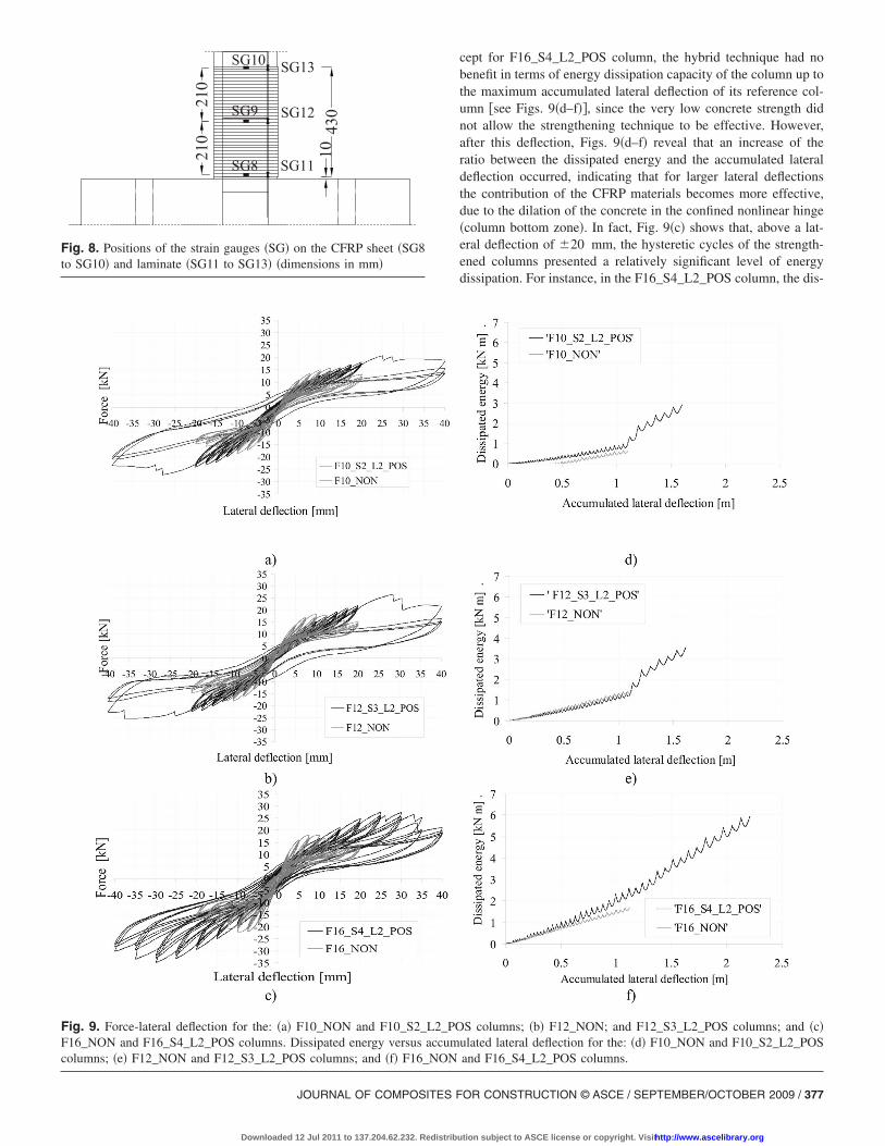
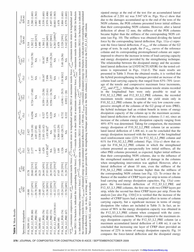
Figs. 9�a–c� represent the force-lateral deflection, F-uAct, �mea-sured by the internal LVDT of the actuator, LVDT/ACTUATORin Fig. 6� for the columns of the G1 group of tests. In each graph,the F-uAct curves of the reference column and its correspondingpoststrengthened column are superimposed to highlight themost relevant features provided by the proposed technique. Therelationship between the dissipated energy and the accumulatedlateral deflection �at LVDT/ACTUATOR� for the tested columnsis represented in Figs. 9�d–f�. The accumulated lateral deflectionwas evaluated adding the absolute values of the recordeddisplacements in all cycles. The main results are presented inTable 3. The sign convention for tensile/compressive forces isrepresented in Fig. 5. From the obtained results, it is verified thatthe hybrid poststrengthening technique provided an increase ofthe column load carrying capacity that ranged from 38%–55%�average of the tensile and compressive maximum force incre-ments, Ft,max
exp and Fc,maxexp �. Due to the very low compressive
strength of the concrete of these columns, the maximum tensilestrain recorded in the longitudinal bars exceeded the yield strainonly for F10_S2_L2_POS column. At the end of the tests, theformation of semiconical fracture surfaces in the concrete sur-rounding the anchorage zone of the laminates was observed andconsidered as a possible justification for the load decays that are
visible in the F-uAct curve of the poststrengthened columns. Ex-OR CONSTRUCTION © ASCE / SEPTEMBER/OCTOBER 2009 / 375
tion subject to ASCE license or copyright. Visithttp://www.ascelibrary.org
Horizontal actuator
20
HEB(L=1000mm)
Vertical actuator
HEB 200
1250
HEB
770225
HEB(L=350mm)
750
20
160
850
800 165
11303060
200
Reaction Wall (800 mm)
150
1500
3500
255
1225
300
100
40HEB
(L=400mm)
Tensile Force
Compressive Force
Reaction Floor (800 mm thickness)
FACE AFACE C
Fig. 5. Test setup
2F(10,12,16)L=800mm
200 200
360
1300 (x1300)
AA
260
260
335
200
250
300
250
LVDT 1
LVDT 2
LVDT 3
LVDT 4
LVDT 5
LVDT 6
LVDT 7
350
[+/- 25 mm]
[+/- 25 mm]
[+/- 12.5 mm]
[+/- 12.5 mm]
(+/- 5 mm)*
(+/- 5 mm)*
(+/- 50 mm)
(+/- 50 mm)
(+/- 25 mm)
(+/- 25 mm)
100
2F(10,12,16)L=800mm
2F(10,12,16)L=1500mm
2F(10,12,16)L=1500mm
100
50
LVDT /ACTUATOR
FACE A
FACE C
1350
[…] For NON columns;(…) For PRE and POS columns
(…)* For NON, PRE and POS columns.
Fig. 6. Position of the LVDTs �all dimensions in mm�
376 / JOURNAL OF COMPOSITES FOR CONSTRUCTION © ASCE / SEPTE
Downloaded 12 Jul 2011 to 137.204.62.232. Redistribu
2FL=1500mm
200
2FL=1500mm
2FL=800mm
200
360
1300 (x1300)
AA
10260
260125
SG2
335
SG1
SG3
SG4
2FL=800mm
125
10
SG5
SG6
SG7
2F
SG(5,6,7)
A - A
BB
Starter barsB - B
Longitudinal bars
Fig. 7. Position of the strain gauges �SG� installed on steel longitu-dinal bars �SG1 to SG4� and on steel hoops �SG5 to SG7� bars �alldimensions in mm�
MBER/OCTOBER 2009
tion subject to ASCE license or copyright. Visithttp://www.ascelibrary.org
JOURNAL OF COMPOSITES F
Downloaded 12 Jul 2011 to 137.204.62.232. Redistribu
cept for F16_S4_L2_POS column, the hybrid technique had nobenefit in terms of energy dissipation capacity of the column up tothe maximum accumulated lateral deflection of its reference col-umn �see Figs. 9�d–f��, since the very low concrete strength didnot allow the strengthening technique to be effective. However,after this deflection, Figs. 9�d–f� reveal that an increase of theratio between the dissipated energy and the accumulated lateraldeflection occurred, indicating that for larger lateral deflectionsthe contribution of the CFRP materials becomes more effective,due to the dilation of the concrete in the confined nonlinear hinge�column bottom zone�. In fact, Fig. 9�c� shows that, above a lat-eral deflection of �20 mm, the hysteretic cycles of the strength-ened columns presented a relatively significant level of energydissipation. For instance, in the F16_S4_L2_POS column, the dis-
S columns; �b� F12_NON; and F12_S3_L2_POS columns; and �c�ulated lateral deflection for the: �d� F10_NON and F10_S2_L2_POSand F16_S4_L2_POS columns.
10
210
210 430
SG8
SG9
SG10
SG11
SG12
SG13
Fig. 8. Positions of the strain gauges �SG� on the CFRP sheet �SG8to SG10� and laminate �SG11 to SG13� �dimensions in mm�
Fig. 9. Force-lateral deflection for the: �a� F10_NON and F10_S2_L2_POF16_NON and F16_S4_L2_POS columns. Dissipated energy versus accumcolumns; �e� F12_NON and F12_S3_L2_POS columns; and �f� F16_NON
OR CONSTRUCTION © ASCE / SEPTEMBER/OCTOBER 2009 / 377
tion subject to ASCE license or copyright. Visithttp://www.ascelibrary.org
T S F F F F F F F F F F F a b i t l b
378 / JOURNAL OF COMPOSITES FOR CONSTRUCTION © ASCE / SEPTE
Downloaded 12 Jul 2011 to 137.204.62.232. Redistribu
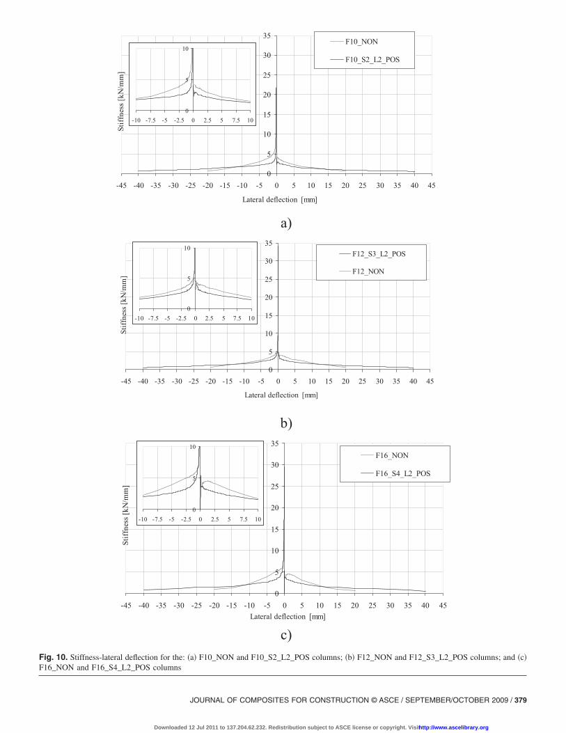
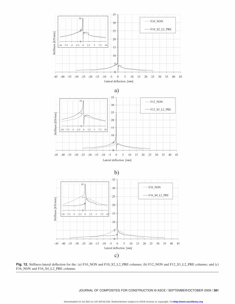
sipated energy at the end of the test �for an accumulated lateraldeflection of 2.201 m� was 5.947 kN m. Figs. 9�a–c� show thatdue to the damages accumulated up to the end of the tests of theNON columns, the POS columns presented lower initial stiffnessthan their corresponding NON columns. However, after a lateraldeflection of about 12 mm, the stiffness of the POS columnsbecame higher than the stiffness of the corresponding NON col-umn �see Fig. 10�. The stiffness was obtained dividing the lateralforce by the corresponding lateral deflection. Figs. 11�a–c� repre-sent the force-lateral deflection, F-uAct, of the columns of the G2group of tests. In each graph, the F-uAct curves of the referencecolumn and its corresponding prestrengthened column are super-imposed to observe the increase in terms of load carrying capacityand energy dissipation provided by the strengthening technique.The relationship between the dissipated energy and the accumu-lated lateral deflection �at LVDT/ACTUATOR� for the tested col-umns is represented in Figs. 11�d–f�. The main results arepresented in Table 3. From the obtained results, it is verified thatthe hybrid prestrengthening technique provided an increase of thecolumn load carrying capacity that ranged from 63%–70% �aver-age of the tensile and compressive maximum force increments,Ft,max
exp and Fc,maxexp �. Although the maximum tensile strains recorded
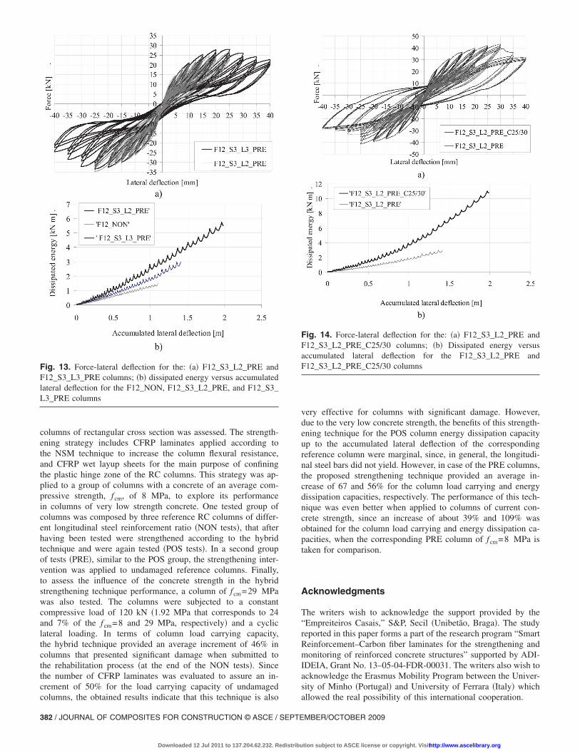
in the longitudinal bars were only possible to read inF10_S2_L2_PRE and F12_S3_L2_PRE columns, the recordedmaximum tensile strains exceeded the yield strain only inF10_S2_L2_PRE column. In spite of the very low concrete com-pressive strength of the columns of the G2 group of tests �PRE�,the hybrid technique had an evident benefit in terms of energydissipation capacity of the column up to the maximum accumu-lated lateral deflection of the reference columns �1.1 m�, since anincrease of the column energy dissipation capacity ranging from40%–87% was determined. Taking for comparison, the maximumenergy dissipation of F10_S2_L2_PRE column �at an accumu-lated lateral deflection of 1.406 m�, it can be concluded that theenergy dissipation increased with the increase of the longitudinalsteel reinforcement ratio �22% for F12_S2_L2_PRE column and61% for F16_S2_L2_PRE column�. Figs. 11�a–c� show that ex-cept for F16_S4_L2_PRE column in which the strengthenedcolumn presented an unexpectedly low initial stiffness, all theother PRE columns presented, as expected, higher initial stiffnessthan their corresponding NON columns, due to the influence ofthe strengthened materials and lack of damage in the columnswhen strengthening intervention was applied. However, after alateral deflection of about 10 mm, even the stiffness of theF16_S4_L2_PRE column became higher than the stiffness ofthe corresponding NON column �see Fig. 12�. To evince the in-fluence of the number of CFRP layers per strip in terms of columnload carrying and energy dissipation capacities, Fig. 13�a� com-pares the force-lateral deflection of F12_S3_L2_PRE andF12_S3_L3_PRE columns, the first one with two CFRP layers perstrip, while the second has three CFRP layers per strip. From theanalysis �see also Fig. 13�b�� it is verified that the increase of thenumber of CFRP layers had a marginal effect in terms of columncarrying capacity, but a significant increase in terms of energydissipation �the values are included in Table 3�. In fact, an in-crease of 96% in the energy dissipation capacity was obtained inthe F12_S3_L3_PRE column when compared with the corre-sponding reference column. When compared to the maximum en-ergy dissipation capacity of the F12_S3_L2_PRE column �at amaximum accumulated lateral deflection of 1.406 m�, it can beconcluded that increasing one layer of CFRP sheet provided anincrease of 22% in terms of energy dissipation capacity. Fig. 14
able3.
Mai
nR
esul
ts
peci
men
desi
gnat
ion
Fc,
max
exp
�kN
�F
t,m
axex
p
�kN
��
sFt,
max
exp
�‰�
�s,
max
Ftex
p
�‰�
�fSh
e,F
c,m
axex
p
�‰�
�f,
max
She,
Fcex
p
�‰�
�fL
am,F
t,m
axex
p
�‰�
�f,
max
Lam
,Ftex
p
�‰�
Ual
d=11
00
�kN
.m�
Ual
d,m
ax
�kN
.m�
10_N
ON
�41�
�18
.80
15.7
82.
427
2.42
7—
——
—1.
314
1.31
4
10_S
2_L
2_PO
S�8
0��
27.2
7�4
5%�
20.6
8�3
1%�
2.17
72.
796
�19.
18�
0.42
960.
724
��17
.68�
3.37
7.76
3�1
9.78
�1.
282
�-�
3.28
0�1
.601
�
10_S
2_L
2_PR
E�5
6�—
29.7
8�5
8%�
28.5
6�8
1%�
44.
05�2
7.88
�N
AN
AN
AN
A1.
849
�41%
�3.
083
�1.5
61�
12_N
ON
�46�
�18
.00
18.2
31.
403
1.53
8�1
7.60
�—
——
—1.
490
1.49
0
12_S
3_L
2_PO
S�7
6��
25.4
7�4
2%�
26.4
4�4
5%�
1.42
92.
101
�21.
62�
0.32
70.
359
��23
.58�
10.1
6710
.167
1.38
4�-
�3.
539
�1.6
01�
12_S
3_L
2_PR
E�5
3��
33.3
8�8
5%�
27.9
3�5
3%�
1.43
5SG
2b1.
435
SG2b
0.17
90.
244
��23
.61�
7.89
67.
896
2.08
8�4
0%�
2.97
9�1
.406
�
12_S
3_L
3_PR
E�7
3��
33.1
3�8
5%�
28.3
5�5
3%�
NA
NA
0.22
90.
556
��24
.78�
2.25
72.
815
�28.
24�
2.92
7�9
6%�
5.49
7�1
.983
�
12_S
3_L
2_PR
E_C
25/3
0�6
1��
41.2
2�2
3%�a
43.2
5�5
5%�a
3.02
77.
487
�42.
17�
NA
NA
NA
NA
6.28
3�1
09%
�a10
.803
�1.9
83�
16_N
ON
�48�
�22
.73
17.6
51.
091.
304
�13.
29�
——
——
1.67
81.
678
16_S
4_L
2_PO
S�7
4��
35.2
4�5
5%�
27.3
8�5
5%�
1.32
61.
905
�20.
77�
0.73
21.
4196
��29
.5�
5.18
SG12
5.48
�26.
56�
2.32
8�3
9%�
3.80
4�1
.601
�
16_S
4_L
2_PR
E�6
7��
33.7
0�4
8%�
31.2
9�7
7%�
NA
NA
0.33
20.
952
��20
�N
AN
A3.
142
�87%
�4.
579
�1.6
01�
Fc,
max
exp
=m
axim
umco
mpr
essi
vefo
rce;
Ft,
max
exp
=m
axim
umte
nsile
forc
e;�
sFt,
max
exp
=te
nsile
stra
inin
long
itudi
nal
stee
lba
rs�S
G1�
atm
axim
umte
nsile
forc
e;�
s,m
axF
texp
=m
axim
umte
nsile
stra
inin
long
itudi
nal
stee
l
ars
�SG
1��i
nbr
acke
tsis
indi
cate
dth
eco
rres
pond
ing
tens
ilefo
rce�
;�
fShe,
Fc,
max
exp
=te
nsile
stra
inin
shee
t�S
G8�
atm
axim
umco
mpr
essi
vefo
rce;
�f,
max
She,
Fcex
p
=m
axim
umte
nsile
stra
inin
shee
t�S
G8�
�in
brac
kets
sin
dica
ted
the
corr
espo
ndin
gco
mpr
essi
vefo
rce�
;�
fLam
,Ft,
max
exp
=te
nsile
stra
inin
lam
inat
es�S
G11
�at
max
imum
tens
ilefo
rce;
�f,
max
Lam
,Ftex
p
=m
axim
umte
nsile
stra
inin
lam
inat
es�S
G11
��i
nbr
acke
tsis
indi
cate
dhe
corr
espo
ndin
gte
nsile
forc
e�;U
ald=
1100
=di
ssip
ated
ener
gyup
toac
cum
ulat
edla
tera
ldefl
ectio
nof
1,10
0m
m;U
ald,
max
=m
axim
umdi
ssip
ated
ener
gy�i
nbr
acke
tsin
indi
cate
dth
eco
rres
pond
ing
accu
mul
ated
ater
alde
flect
ion�
;�
�ag
e,in
days
,at
test
ing;
and
��
incr
ease
prov
ided
byth
est
reng
then
ing
tech
niqu
ean
dre
ferr
edto
the
NO
Nco
lum
ns;
��
incr
ease
refe
rred
toth
eF1
2_S3
_L2_
PRE
colu
mn.
Mea
sure
din
SG2,
sinc
eSG
1w
asno
tw
orke
d.
compares the force-lateral deflection and the dissipated energy
MBER/OCTOBER 2009
tion subject to ASCE license or copyright. Visithttp://www.ascelibrary.org
0
5
10
15
20
25
30
35
-45 -40 -35 -30 -25 -20 -15 -10 -5 0 5 10 15 20 25 30 35 40 45
Lateral deflection [mm]
Stiffness[kN/mm]
F10_NON
F10_S2_L2_POS
0
5
10
-10 -7.5 -5 -2.5 0 2.5 5 7.5 10
a)
0
5
10
15
20
25
30
35
-45 -40 -35 -30 -25 -20 -15 -10 -5 0 5 10 15 20 25 30 35 40 45
Lateral deflection [mm]
Stiffness[kN/mm]
F12_S3_L2_POS
F12_NON
0
5
10
-10 -7.5 -5 -2.5 0 2.5 5 7.5 10
b)
0
5
10
15
20
25
30
35
-45 -40 -35 -30 -25 -20 -15 -10 -5 0 5 10 15 20 25 30 35 40 45Lateral deflection [mm]
Stiffness[kN/mm]
F16_NON
F16_S4_L2_POS
0
5
10
-10 -7.5 -5 -2.5 0 2.5 5 7.5 10
c)Fig. 10. Stiffness-lateral deflection for the: �a� F10_NON and F10_S2_L2_POS columns; �b� F12_NON and F12_S3_L2_POS columns; and �c�F16_NON and F16_S4_L2_POS columns
JOURNAL OF COMPOSITES FOR CONSTRUCTION © ASCE / SEPTEMBER/OCTOBER 2009 / 379
Downloaded 12 Jul 2011 to 137.204.62.232. Redistribution subject to ASCE license or copyright. Visithttp://www.ascelibrary.org
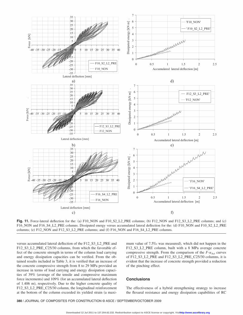
versus accumulated lateral deflection of the F12_S3_L2_PRE andF12_S3_L2_PRE_C25/30 columns, from which the favorable ef-fect of the concrete strength in terms of the column load carryingand energy dissipation capacities can be verified. From the ob-tained results included in Table 3, it is verified that an increase ofthe concrete compressive strength from 8 to 29 MPa provided anincrease in terms of load carrying and energy dissipation capaci-ties of 39% �average of the tensile and compressive maximumforce increments� and 109% �for an accumulated lateral deflectionof 1.406 m�, respectively. Due to the higher concrete quality ofF12_S3_L2_PRE_C25/30 column, the longitudinal reinforcement
-35-30-25-20-15-10-505101520253035
-40 -35 -30 -25 -20 -15 -10 -5 0 5 10 15 20 25 30 35
Lateral deflection [mm]
Force[kN]
F10_S2_L2_PRE
F10_NON
a)
-35-30-25-20-15-10-505101520253035
-40 -35 -30 -25 -20 -15 -10 -5 0 5 10 15 20 25 30 35
Lateral deflection [mm]
Force[kN]
.
F12_S3_L2_PR
F12_NON
b)
-35-30-25-20-15-10-505101520253035
-40 -35 -30 -25 -20 -15 -10 -5 0 5 10 15 20 25 30 35 4
Lateral deflection [mm]
Force[kN]
.
F16_S4_L2_PRE
F16_NON
c)
Fig. 11. Force-lateral deflection for the: �a� F10_NON and F10_S2_F16_NON and F16_S4_L2_PRE columns. Dissipated energy versuscolumns; �e� F12_NON and F12_S3_L2_PRE columns; and �f� F16_
at the bottom of the column exceeded its yielded strain �a maxi-
380 / JOURNAL OF COMPOSITES FOR CONSTRUCTION © ASCE / SEPTE
Downloaded 12 Jul 2011 to 137.204.62.232. Redistribu
mum value of 7.5‰ was measured�, which did not happen in theF12_S3_L2_PRE column, built with a 8 MPa average concretecompressive strength. From the comparison of the F-uAct curvesof F12_S3_L2_PRE and F12_S3_L2_PRE_C25/30 columns, it isevident that the increase of concrete strength provided a reductionof the pinching effect.
Conclusions
The effectiveness of a hybrid strengthening strategy to increase
0
1
2
3
4
5
6
7
0 0.5 1 1.5 2 2.5Accumulated lateral deflection [m]
Dissipatedenergy[kNm].
'F10_NON'
' F10_S2_L2_PRE'
d)
0
1
2
3
4
5
6
7
0 0.5 1 1.5 2 2.5
Accumulated lateral deflection [m]
Dissipatedenergy[kNm].
F12_S3_L2_PRE'
'F12_NON'
e)
0
1
2
3
4
5
6
7
0 0.5 1 1.5 2 2.5Accumulated lateral deflection [m]
Dissipatedenergy[kNm].
' F16_NON'
' F16_S4_L2_PRE'
f)
RE columns; �b� F12_NON and F12_S3_L2_PRE columns; and �c�ulated lateral deflection for the: �d� F10_NON and F10_S2_L2_PREand F16_S4_L2_PRE columns.
40
40
E
0
L2_PaccumNON
the flexural resistance and energy dissipation capabilities of RC
MBER/OCTOBER 2009
tion subject to ASCE license or copyright. Visithttp://www.ascelibrary.org
0
5
10
15
20
25
30
35
-45 -40 -35 -30 -25 -20 -15 -10 -5 0 5 10 15 20 25 30 35 40 45Lateral deflection [mm]
Stiffness[kN/mm]
F10_NON
F10_S2_L2_PRE
0
5
10
-10 -7.5 -5 -2.5 0 2.5 5 7.5 10
a)
0
5
10
15
20
25
30
35
-45 -40 -35 -30 -25 -20 -15 -10 -5 0 5 10 15 20 25 30 35 40 45
Lateral deflection [mm]
Stiffness[kN/mm]
F12_NON
F12_S3_L2_PRE
0
5
10
-10 -7.5 -5 -2.5 0 2.5 5 7.5 10
b)
0
5
10
15
20
25
30
35
-45 -40 -35 -30 -25 -20 -15 -10 -5 0 5 10 15 20 25 30 35 40 45Lateral deflection [mm]
Stiffness[kN/mm]
F16_NON
F16_S4_L2_PRE
0
5
10
-10 -7.5 -5 -2.5 0 2.5 5 7.5 10
c)Fig. 12. Stiffness-lateral deflection for the: �a� F10_NON and F10_S2_L2_PRE columns; �b� F12_NON and F12_S3_L2_PRE columns; and �c�F16_NON and F16_S4_L2_PRE columns
JOURNAL OF COMPOSITES FOR CONSTRUCTION © ASCE / SEPTEMBER/OCTOBER 2009 / 381
Downloaded 12 Jul 2011 to 137.204.62.232. Redistribution subject to ASCE license or copyright. Visithttp://www.ascelibrary.org
columns of rectangular cross section was assessed. The strength-ening strategy includes CFRP laminates applied according tothe NSM technique to increase the column flexural resistance,and CFRP wet layup sheets for the main purpose of confiningthe plastic hinge zone of the RC columns. This strategy was ap-plied to a group of columns with a concrete of an average com-pressive strength, fcm, of 8 MPa, to explore its performancein columns of very low strength concrete. One tested group ofcolumns was composed by three reference RC columns of differ-ent longitudinal steel reinforcement ratio �NON tests�, that afterhaving been tested were strengthened according to the hybridtechnique and were again tested �POS tests�. In a second groupof tests �PRE�, similar to the POS group, the strengthening inter-vention was applied to undamaged reference columns. Finally,to assess the influence of the concrete strength in the hybridstrengthening technique performance, a column of fcm=29 MPawas also tested. The columns were subjected to a constantcompressive load of 120 kN �1.92 MPa that corresponds to 24and 7% of the fcm=8 and 29 MPa, respectively� and a cycliclateral loading. In terms of column load carrying capacity,the hybrid technique provided an average increment of 46% incolumns that presented significant damage when submitted tothe rehabilitation process �at the end of the NON tests�. Sincethe number of CFRP laminates was evaluated to assure an in-crement of 50% for the load carrying capacity of undamaged
Fig. 13. Force-lateral deflection for the: �a� F12_S3_L2_PRE andF12_S3_L3_PRE columns; �b� dissipated energy versus accumulatedlateral deflection for the F12_NON, F12_S3_L2_PRE, and F12_S3_L3_PRE columns
columns, the obtained results indicate that this technique is also
382 / JOURNAL OF COMPOSITES FOR CONSTRUCTION © ASCE / SEPTE
Downloaded 12 Jul 2011 to 137.204.62.232. Redistribu
very effective for columns with significant damage. However,due to the very low concrete strength, the benefits of this strength-ening technique for the POS column energy dissipation capacityup to the accumulated lateral deflection of the correspondingreference column were marginal, since, in general, the longitudi-nal steel bars did not yield. However, in case of the PRE columns,the proposed strengthening technique provided an average in-crease of 67 and 56% for the column load carrying and energydissipation capacities, respectively. The performance of this tech-nique was even better when applied to columns of current con-crete strength, since an increase of about 39% and 109% wasobtained for the column load carrying and energy dissipation ca-pacities, when the corresponding PRE column of fcm=8 MPa istaken for comparison.
Acknowledgments
The writers wish to acknowledge the support provided by the“Empreiteiros Casais,” S&P, Secil �Unibetão, Braga�. The studyreported in this paper forms a part of the research program “SmartReinforcement–Carbon fiber laminates for the strengthening andmonitoring of reinforced concrete structures” supported by ADI-IDEIA, Grant No. 13–05-04-FDR-00031. The writers also wish toacknowledge the Erasmus Mobility Program between the Univer-sity of Minho �Portugal� and University of Ferrara �Italy� which
Fig. 14. Force-lateral deflection for the: �a� F12_S3_L2_PRE andF12_S3_L2_PRE_C25/30 columns; �b� Dissipated energy versusaccumulated lateral deflection for the F12_S3_L2_PRE andF12_S3_L2_PRE_C25/30 columns
allowed the real possibility of this international cooperation.
MBER/OCTOBER 2009
tion subject to ASCE license or copyright. Visithttp://www.ascelibrary.org
References
Barros, J. A. O., and Ferreira, D. R. S. M. �2008�. “Assessing the effi-ciency of CFRP discrete confinement systems for concrete columnelements.” J. Compos. Constr., 12�2�, 134–148.
Barros, J. A. O., Ferreira, D. R. S. M., Fortes, A. S., and Dias, S. J. E.�2006�. “Assessing the effectiveness of embedding CFRP laminates inthe near surface for structural strengthening.” Constr. Build. Mater.,20�7�, 478–491.
Barros, J. A. O., and Fortes, A. S. �2005�. “Flexural strengthening ofconcrete beams with CFRP laminates bonded into slits.” Cem. Concr.Compos., 27�4�, 471–480.
Barros, J. A. O., and Kotynia, R. �2008�. “Possibilities and challenges ofNSM for the flexural strengthening of RC structures.” Proc., 4th Int.Conf. on FRP Composites in Civil Engineering (CICE2008), Zurich,Switzerland.
Berthet, J. F., Ferrier, E., and Hamelin, P. �2005�. “Compressive behaviorof concrete externally confined by composite jackets.” Constr. Build.Mater., 19�3�, 223–232.
Bonaldo, E., Barros, J. A. O., and Lourenço, P. B. �2008�. “Efficientstrengthening technique to increase the flexural resistance of existingRC slabs.” J. Compos. Constr., 12�2�, 149–159.
Bournas, D. A., and Triantafillou, T. C. �2008�. “Experimental investiga-tion of flexurally strengthened RC columns with near surface mountedFRP or stainless steel reinforcement.” Proc., Challenges for CivilConstruction Int. Conf. (CCC2008) �CD-ROM�, Porto, Portugal,T5–3.
Carolin, A. �2003�. “Carbon fiber reinforced polymers for strengtheningof structural elements.” Ph.D. thesis, Luleå Univ. of Technology,Sweden.
CEB-FIP. �1993�. “CEB-FIP model code 1990.” Bulletin d’Information203, 204, and 205, Comité Euro-International du Béton, Lausanne,Switzerland.
De Lorenzis, L., and Teng, J. G. �2007�. “Near-surface mounted FRPreinforcement: An emerging technique for strengthening structures.”Composites, Part B, 38, 119–142.
El-Hacha, R., and Rizkalla, S. H. �2004�. “Near-surface-mounted fiber-reinforced polymer reinforcements for flexural strengthening of
JOURNAL OF COMPOSITES F
Downloaded 12 Jul 2011 to 137.204.62.232. Redistribu
concrete structures.” ACI Struct. J., 101�5�, 717–726.International Organization for Standardization �ISO�. �1997�. “Plastics—
Determination of tensile properties. Part 5: Test conditions for uni-directional fiber-reinforced plastic composites.” ISO, Genèva,Switzerland.
Jung, W.-T., Park, Y.-H., Park, J.-S., Kang, J.-Y., and You, Y.-J. �2005�.“Experimental investigation on flexural behavior of RC beamsstrengthened by NSM CFRP reinforcements.” Proc., 7th Int. Symp.,Fiber-Reinforced (FRP) Polymer Reinforcement for ConcreteStructures—FRPRCS-7, C. K. Shield, J. P. Busel, S. L. Walkup, andD. D. Gremel, eds., American Concrete Institute, Farmington Hills,Mich., 795–806.
Kotynia, R. �2005�. “Strengthening of reinforced concrete structures withnear surface mounted FRP reinforcement.” Proc., 5th Int. Conf.—Analytical Models and New Concepts in Concrete and Masonry Struc-tures AMCM 2005, Gliwice-Ustroń, 8.
Lin, H. J., and Liao, C. I. �2004�. “Compressive strength of rein-forced concrete column confined by composite material.” J. Compos.Constr., 65�2�, 239–250.
NP-EN 10002–1. �1990�. “Metallic materials—Tensile testing. Part 1:Method of test �at ambient temperature�.” European standard, CEN,Brussels, Belgium.
Perrone, M. �2008�. “Hybrid CFRP-based strengthening technique for RCcolumns subjected to axial and cyclic lateral loading.” MS thesis,Univ. of Ferrara, Italy.
Saadatmanesh, H., Ehsani, M. R., and Jin, M. W. �1996�. “Seismicstrengthening of circular bridge pier models with fiber composites.”ACI Struct. J., 93�6�, 639–647.
Saadatmanesh, H., Ehsani, M. R., and Jin, M. W. �1997�. “Repair ofearthquake-damaged RC columns with FRP wraps.” ACI Struct. J.,94�2�, 206–215.
Saadatmanesh, H., Ehsani, M. R., and Li, M. W. �1994�. “Strength andductility of concrete columns externally reinforced with fiber compos-ite straps.” ACI Struct. J., 91�4�, 434–447.
Yalcin, C., Kaya, O., and Sinangil, M. �2008�. “Seismic retrofitting of RCcolumns having plain rebars using CFRP sheets for improved strengthand ductility.” Constr. Build. Mater., 22�3�, 295–307.
OR CONSTRUCTION © ASCE / SEPTEMBER/OCTOBER 2009 / 383
tion subject to ASCE license or copyright. Visithttp://www.ascelibrary.org
Related Documents