Consultation draft Choice Framework for local Policy and Procedures CFPP 01-01: Management and decontamination of surgical instruments used in acute care Part C – Steam sterilization Consultation draft January 2012

Welcome message from author
This document is posted to help you gain knowledge. Please leave a comment to let me know what you think about it! Share it to your friends and learn new things together.
Transcript

Consu
ltatio
n
draf
t
Choice Framework for local Policy and Procedures CFPP 01-01: Management and decontamination of surgical instruments used in acute care Part C – Steam sterilization Consultation draft January 2012
Consu
ltatio
n
draf
t
2 of 121
Contents 1.0 Types and methods of sterilization ...................................................................................... 7
Steam sterilization ..................................................................................................................................................... 7
2 Specification and contract ....................................................................................................... 9
Introduction ............................................................................................................................................................... 9
CE marking ............................................................................................................................................................... 9
Preparing a specification ........................................................................................................................................... 9
Porous-load sterilizers ............................................................................................................................................ 10
3 Validation and verification: introduction .............................................................................. 16
4 Testing: IQ tests ...................................................................................................................... 17
Installation tests ...................................................................................................................................................... 17
Checks on sterilizers ............................................................................................................................................... 17
Sound power test .................................................................................................................................................... 20
5.0 Schedule of validation tests ................................................................................................ 21
Introduction ............................................................................................................................................................. 21
6.0 Schedule of periodic tests ................................................................................................... 22
Introduction ............................................................................................................................................................. 22
7.0 Performance Qualification tests ......................................................................................... 24
Position of PQ sensors ........................................................................................................................................... 24
Thermometric test for PQ ........................................................................................................................................ 25
Microbiological test for PQ ...................................................................................................................................... 26
Permitted tolerances ............................................................................................................................................... 26
8.0 Test methods ........................................................................................................................ 29
Automatic control test ............................................................................................................................................. 29
Air leakage test ....................................................................................................................................................... 30
Air detector tests ..................................................................................................................................................... 30
Thermometric test for a small load .......................................................................................................................... 30
Thermometric test for a full load ............................................................................................................................. 30
Load dryness test .................................................................................................................................................... 31

Consu
ltatio
n
draf
t
3 of 121
Hospital load dryness check ................................................................................................................................... 31
Bowie-Dick test for steam penetration .................................................................................................................... 31
Hollow load test ....................................................................................................................................................... 31
Dynamic pressure test ............................................................................................................................................ 31
9.0 Testing: additional information ........................................................................................... 32
Standard test pack .................................................................................................................................................. 33
Use of chemical indicators ...................................................................................................................................... 33
Use of biological indicators ..................................................................................................................................... 34
Specifications .......................................................................................................................................................... 34
General procedure for microbiological tests ........................................................................................................... 35
Weekly safety checks ............................................................................................................................................. 35
Yearly safety checks ............................................................................................................................................... 35
10.0 Steam supply ...................................................................................................................... 37
Engineering considerations ..................................................................................................................................... 37
Dryness ................................................................................................................................................................... 39
Superheating ........................................................................................................................................................... 40
Non-condensable gases ......................................................................................................................................... 41
Steam quality – responsibilities ............................................................................................................................... 42
11.0 Contamination in steam supplies ..................................................................................... 44
Introduction ............................................................................................................................................................. 44
Why does contamination matter? ........................................................................................................................... 44
Products vulnerable to steam-borne contamination ................................................................................................ 45
Sources of contamination ....................................................................................................................................... 46
12.0 Steam quality requirements .............................................................................................. 49
13.0 Steam in practice ................................................................................................................ 50
Introduction ............................................................................................................................................................. 50
How steam is made ................................................................................................................................................ 50
Summary of requirements for steam ....................................................................................................................... 50
Steam from the mains steam supply ....................................................................................................................... 51
Steam from a dedicated generator ......................................................................................................................... 53

Consu
ltatio
n
draf
t
4 of 121
14.0 Testing for compliance ...................................................................................................... 57
Where to take samples ........................................................................................................................................... 57
Validation and periodic testing ................................................................................................................................ 57
Dedicated steam generator ..................................................................................................................................... 59
15.0 Sampling ............................................................................................................................. 62
Sampling points ...................................................................................................................................................... 62
Sampling for field analysis ...................................................................................................................................... 62
Sampling for laboratory analysis ............................................................................................................................. 66
Handling of samples for laboratory analysis ........................................................................................................... 66
Analysis of samples ................................................................................................................................................ 69
16.0 Physical steam quality tests ............................................................................................. 72
Non-condensable gas test ...................................................................................................................................... 72
Superheat test ......................................................................................................................................................... 74
Dryness test ............................................................................................................................................................ 76
17.0 Operation and maintenance of steam generators ........................................................... 79
Introduction ............................................................................................................................................................. 79
Operation ................................................................................................................................................................ 79
Maintenance ........................................................................................................................................................... 79
18.0 Pyrogens ............................................................................................................................. 81
Bacterial endotoxins ................................................................................................................................................ 81
Clinical significance ................................................................................................................................................. 81
Detection and measurement ................................................................................................................................... 81
Generation of bacterial endotoxin ........................................................................................................................... 82
Regulatory requirements ......................................................................................................................................... 83
Requirements for steam .......................................................................................................................................... 83
Summary ................................................................................................................................................................. 84
19.0 Tests for steam ................................................................................................................... 86
Laboratory tests for chemical purity ........................................................................................................................ 86
Field test for pH and electrical conductivity ............................................................................................................. 86
20.0 General ................................................................................................................................ 89

Consu
ltatio
n
draf
t
5 of 121
Introduction ............................................................................................................................................................. 89
21.0 Operational management: an overview ........................................................................... 90
Introduction ............................................................................................................................................................. 90
Compatibility of load and process ........................................................................................................................... 90
Cleaning .................................................................................................................................................................. 91
Cycle variables ........................................................................................................................................................ 91
Cycle monitoring and documentation ...................................................................................................................... 91
Product release ....................................................................................................................................................... 92
Storage ................................................................................................................................................................... 93
Record-keeping ....................................................................................................................................................... 93
Sterilizer process log ............................................................................................................................................... 95
22.0 Maintenance ........................................................................................................................ 97
Introduction ............................................................................................................................................................. 97
Competent Person (Decontamination) .................................................................................................................... 97
Planned maintenance programme .......................................................................................................................... 97
Pressure Systems Safety Regulations .................................................................................................................. 100
Features requiring special attention ...................................................................................................................... 100
Returning a sterilizer to service ............................................................................................................................. 101
Door interlocks ...................................................................................................................................................... 102
23.0 Operation of porous-load sterilizers .............................................................................. 103
Introduction ........................................................................................................................................................... 103
The process .......................................................................................................................................................... 103
Product compatibility ............................................................................................................................................. 103
Design of the load ................................................................................................................................................. 104
Troubleshooting .................................................................................................................................................... 105
Appendix A: Particular specification for porous load sterilizers ........................................ 109

Consu
ltatio
n
draf
t
6 of 121
Section 1: Design and pre-‐purchase considerations

Consu
ltatio
n
draf
t
7 of 121
1.0 Types and methods of sterilization 1.1 This guidance document deals with clinical sterilizers, not laboratory sterilizers (see CFPP 01-02). It only covers the central reprocessing of medical devices in sterile services departments (SSDs). The use of small sterilizers is covered in Health Technical Memorandum 01-05 and CFPP 01-07.
1.2. Loads intended for processing in a clinical sterilizer should not be put into a laboratory sterilizer and vice versa.
Steam sterilization
Sterilants 1.3 Within this CFPP, sterilizers can be classified according to the agent (the sterilant) used to effect sterilization. The following sterilants are in common use:
a. high-temperature steam;
b. other processes, including low temperature processes, will be discussed in Part E.
1.4 Because of its superior sterilizing qualities, high-temperature steam should be used as the preferred sterilant. Machines using other sterilants should be reserved either for loads that would be damaged by exposure to high-temperature steam (such as certain surgical devices) or for loads that would not be sterilized by exposure to high-temperature steam.
1.5 The operating cycles are designed to cope with the differing properties of the various types of load, and a sterilizer should only be used for the type of load for which it is designed.
1.6 Similarly, a container with a small orifice will also require a porous-load sterilizer but the duration of each air removal pulse should be extended to allow for pressure equilibration; otherwise the air will remain in the container and sterilization will not be achieved. Guidance on the modification of operating cycles to suit particular loads (process development) should be sought from the AE(D)
1.7 Advice should be sought from the AE(D) before any decision is made regarding the sterilization process.
1.8 Once the type of sterilizer has been chosen, preliminary enquires should be made with a number of manufacturers. The use of the ‘Particular specification’ (see Appendix A) will enable data provided by the tenderer on technical points as well as financial data to be compared. Not only will this enable the purchaser to confirm the acceptability of current services, spatial requirements and porterage but also it will enable a like-for-like tender analysis to be made. Tender analysis will be best achieved by formalizing tender comparison with respect to performance and cost in all key areas. Qualifying statements by the tenderer should be taken into account and their effect on tender content or eligibility should be made prior to a choice being made (see Appendix A).
Sterilization conditions 1.9 Time–temperature relationships are shown in Table 1.

Consu
ltatio
n
draf
t
8 of 121
High temperature steam Sterilization temperature [C]a 121 134 Maximum temperature [C] 124 137 Minimum holding time [min] 15 3 a. The temperature setting on the automatic controller will not generally be the sterilization temperature, but a higher temperature within the sterilization temperature band.
Table 1 Sterilization temperature bands
Cycle time 1.10 The time required to complete an operating cycle depends both on the design of the sterilizer (especially the methods used to remove air from the chamber and to heat and cool the load) and on the type and size of load to be processed.
1.11 Loading conditions that present a greater challenge to the cycle than the loads specified in Section 2 (validation and verification) should be further investigated and PQ should be carried out to establish process conditions. The AE(D) should advise on this.
Chamber size 1.12 The size of a sterilizer is denoted by the volume of the usable chamber space, commonly expressed in litres. The usable chamber space is the space inside the chamber which is not restricted by chamber furniture and which is available to accept the load. It should be distinguished from the total chamber volume, which is equal to the volume of water required to fill the chamber and is therefore larger than the usable chamber space.
1.13 BS EN 285 specifies that the size of large sterilizers should be denoted by the number of sterilization modules that can be accommodated within the usable chamber space: one module is a rectangular shape measuring 300 x 300 x 600 mm with a volume of 54 L. A large sterilizer can accommodate one or more modules.
Sizing calculation 1.14 For SSDs the HBN 13 Capacity Planning Tool should be used for sterilizer sizing requirements [insert hyperlink to HBN13 on Space for Health].
1.15 Where more than one sterilizer of the same type is installed, they should be of the same size and from the same manufacturer. This will allow common loading systems to be used, common spare part inventories to be kept and easier management of maintenance, training and service requirements of CP(D) and AP(D). Sourcing of common equipment may be of benefit.
1.16 If further sterilizers are likely to be purchased in the future, then consideration should be given to the extra space required both in the plantroom and in the loading area.

Consu
ltatio
n
draf
t
9 of 121
2 Specification and contract
Introduction 2.1 This chapter discusses general specifications for sterilizers and the steps to be taken in inviting tenders and issuing a contract.
CE marking 2.2. Sterilizers are covered by a number of European Directives and are thus required to be in conformance. Relevant Directives include but are not restricted to: Medical Device Directive (93/42/EEC and 2007/47/EEC) Class II a, Electromagnetic Compatibility Directive (89/336/EEC), Low-voltage Directive (73/23/EEC), Pressure Equipment Directive (97/23/EEC) and the Machinery Directive (98/37/EEC and 2006/42/EEC).
Preparing a specification 2.3 It is essential that the preparation of procurement specifications be carried out by a qualified and competent person. The purchaser should employ the services of an AE(D) for this purpose.
2.4 Purchasers should refer to BS EN 285 plus CFPP Part B and the ‘Particular specification’ included in Appendix A when preparing a specification for a sterilizer.
Water services to the sterilizer 2.5 A cold water supply may be needed for equipment such as condensers, heat exchangers and water-sealed vacuum pumps (feed-water for steam generation is discussed in Section 3). Details of the water-quality requirements, the maximum pressure, minimum pressure and maximum flow rate should be obtained from the sterilizer manufacturer.
2.6 Backflow prevention devices should be provided on the water supply as required by the local water supply regulations.
2.7 The temperature of water used for sterilizers with vacuum systems should not exceed the value specified by the manufacturer. Higher water temperatures will reduce the efficiency of vacuum pumps and compromise the specified vacuum levels.
2.8 Performance will also deteriorate if the water is very hard or contains large quantities of solids in suspension. The hardness of the water should be in the range 0.7–2.0 mmol L–1. Hardness values outside these limits may cause scaling and corrosion problems.
2.9 Water economy devices (e.g. those which sense the temperature of cooling water and adjust the flow rate accordingly) should be fitted to reduce water consumption.
2.10 Chlorine and chlorides may cause corrosion of stainless steel in the presence of heat. Advice on maximum permissible levels should be obtained from the sterilizer manufacturer.
2.11 Further guidance on water supply is given in Health Technical Memorndum 04-01.

Consu
ltatio
n
draf
t
10 of 121
Drainage 2.12 Condensate should be recovered wherever possible and returned to the steam generation plant provided the quality of the feed water to the boiler is not compromised or the condensate is not corrosive.
2.13 All other effluent from a sterilizer is potentially contaminated and should be disposed of to the main drain. Effluent can originate from one or more of the following sources:
a. air, condensate and steam from the chamber drain, which can contain chemicals and microorganisms;
b. discharge from a water-sealed vacuum pump, ejector or chamber vent, which can also contain microorganisms;
c water introduced to cool and dilute the discharge from the chamber.
Non-hazardous effluents 2.14 Effluent from steam sterilizers and associated equipment should be connected to drain in a manner which provides backflow protection and consistent with local regulations.
2.15 Where a tank supplies water to a water-sealed vacuum pump or a water pump used for an ejector vacuum system, the overflow discharge from the tank should also include an air break.
General plantroom ventilation 2.16 General plantroom ventilation should ensure acceptable working conditions for equipment and personnel are maintained. Ideally the sterilizer plantroom should be on an external wall with appropriate ventilation where practicable (see also HBN 13).
2.17 Where the plantroom does not have an outside wall, heat emissions should be absorbed by a recirculating cooling unit with remote fan-cooled condensers. The rating of the units should have sufficient reserve capacity to reduce the temperature to 30°C in order to provide a safe and acceptable working environment for staff during maintenance of the plant. Additional plant space should be allowed for the installation of the cooling units.
Porous-load sterilizers
2.18 This section discusses sterilizers designed to process porous items such as towels, gowns and dressings, plus medical and surgical equipment, instruments and utensils that are packaged or wrapped in porous materials such as paper, fabrics or sterilization containers with filters. Sterilizers using high temperature steam to process porous loads are commonly known as “porous-load sterilizers”.
2.19 Porous-load sterilizers are distinguished from other high-temperature steam sterilizers by the following features:
a. as porous loads trap both air and moisture, the sterilizer has a vacuum system to ensure that sufficient air is removed from the chamber and load before steam is admitted to the chamber. It also ensures that the pressure during the drying stage is sufficiently reduced so that the load is sensibly dry on completion of the cycle;

Consu
ltatio
n
draf
t
11 of 121
b. an air detector is fitted to the chamber to ensure that the plateau period cannot start until sufficient air has been removed from the chamber;
c. a heated jacket is used to prevent condensate from forming on the chamber walls and to assist drying of the load.
Standard specifications 2.20 Porous-load sterilizers should conform to the specifications in BS EN 285 and the safety specifications in BS EN 61010-2-040. Use should also be made of the ‘Particular specification’ for sterilizers (see Appendix A).
Additional specifications
Air detector 2.21 BS EN 285 requires that there are methods in place to ensure that the requirement for steam penetration throughout the chamber and load is achieved for each cycle. This should be done by specifying an air detector that will abort the cycle if sufficient air and other non-condensable gases have not been removed from the chamber. The correct functioning of the air detector is crucial to the performance of the sterilizer.
Port for air-flow metering device
2.22 An air-flow metering device used for testing air-detector performance and chamber integrity should be fitted to the test port on the side of the sterilizer, preferably towards the lower front
Absolute pressure indicator
2.23 For leak-testing purposes an absolute pressure indicator (0 to 160 mbar) should be fitted, conforming to BS EN 285.
Bowie-Dick test for steam penetration
2.24 Sterilization is achieved by the rapid and even penetration of steam into all parts of the load and the maintenance of these conditions for the specified holding time and temperature. To ensure this, it is essential to remove air from the chamber and load, and to provide a steam supply that contains a minimal volume of non-condensable gases. Any residual air and non-condensable gases will become concentrated as a bubble in the load and inhibit steam penetration.
2.25 The Bowie-Dick test shows whether or not air removal from and steam penetration into a standardised test pack is even and rapid, and thus by implication that air or other non-condensable gases are absent. It does not confirm that the sterilization conditions in the load have been achieved.
Principle of the test
2.26 The original Bowie-Dick test made use of autoclave tape stuck to a piece of A4 size paper to form a St Andrew’s cross. This paper sheet was placed into the centre of a stack of folded huckaback towels. The stack of towels was then placed into the centre of the sterilizer chamber and exposed to a cycle. Upon recovery from the towel pack the indicator paper would be

Consu
ltatio
n
draf
t
12 of 121
examined for colour change. If air had been removed then steam would rapidly penetrate the towel pack and cause the indicator ink on the autoclave tape to completely change colour. The presence of residual air in the towels would create an air pocket protecting the ink from the effects of steam resulting in an uneven colour change across the surface. The indicator tape showed a change of colour in response to a combination of time, temperature and moisture.
2.27 Today the Bowie-Dick test is described in BS EN 285 and involves a test in which a stack of plain cotton sheets is used of a similar size to that of the original test. The stack weighs 7 kg and uses a pre-printed chemical indicator sheet complying with BS EN ISO 11140-3. Manufacturers’ instructions should always be followed when using such indicator sheets.
2.28 When used in conjunction with a standard test pack, indicator sheets complying to BS EN 11140-3 are designed to show a failure when, at the start of the holding time, the temperature at the centre of the test pack is 2°C or more below the temperature in the active chamber discharge caused by the presence of residual air.
2.29 The textile test packs are usually used by the engineering community to conduct validation studies and the periodic tests described elsewhere. For convenience it is common to use commercially produced Bowie and Dick test packs and devices for conducting the daily test. In such circumstances, the product should conform to BS EN ISO 11140-4, and manufacturers’ instructions should be followed. Third-party certification of conformance is desirable.
Bowie-Dick test procedure
2.30 The Bowie-Dick test is normally preceded by a warm-up cycle. This cycle is necessary because the effectiveness of air removal will depend on all parts of the sterilizer being at working temperature. A satisfactory sterilizer may give a fail result if a warm-up run is not carried out. Similarly, conducting a warm up run will clear the steam supply system of any non-condensable gases that have accumulated during periods when the sterilizer is unused.
2.31 Remove the wrapping from a standard test pack and place an indicator sheet compliant with BS EN ISO 11140-3 in the centre of the pack. Reassemble and secure the pack and replace the wrapping.
2.32 Alternatively prepare the commercially produced Bowie-Dick test pack or device as directed by the manufacturer’s instructions.
2.33 Place the test pack (either the towel pack or the commercial alternative) in the chamber with the bottom of the pack supported 100–200 mm above the centre of the chamber base.
2.34 Select the Bowie-Dick test cycle. Ensure that the holding time will not be longer than that specified in Table 2. If this time is exceeded, the indicator may be affected in such a way as to make it difficult to detect a fail condition. Start the operating cycle.
Sterilization holding time temperature (°C) Minimum Maximum (minutes) (minutes)
134 3.3 3.5
Table 2 Holding time for the Bowie-Dick test cycle
2.35 If a holding temperature other than that specified in Table 2 is in use, then the holding time specified by the manufacturer of the indicator sheet or alternative Bowie-Dick test pack or device should be used.

Consu
ltatio
n
draf
t
13 of 121
2.36 During the holding time, note the reading on the cycle counter, the chamber temperature indicator and the chamber pressure indicator.
2.37 When the cycle is complete, remove the indicator paper from the test pack and record the result or record the result from the test device according to the manufacturers instructions.
2.38 The test should be considered satisfactory if the following requirements are met:
a. there is a uniform colour change throughout the indicator sheet or the alternative device gives a response indicative of a satisfactory result according to manufacturers instructions;
b. the automatic controller indicates that a Bowie-Dick test cycle has just been completed.
2.39 For printed indicator sheets it is important to compare the colour of the indicator at the corners of the paper with that at the centre so that any difference can be clearly seen. If there is any discernible difference the test should be recorded as failed, and the paper marked accordingly. A large area of unchanged indicator points to a gross failure.
2.40 The result of the Bowie-Dick test should be recorded in process records. The indicator paper may be marked with the result and kept for reference however in some cases the chemical reaction giving rise to the colour change may continue during storage giving rise to a change in appearance. Process records are legal documents and should be kept for a period of time consistent with local policies and procedures.
2.41 An unsatisfactory Bowie-Dick test result indicates that the sterilizer should not be used until the fault has been identified and rectified. It is important to realise that if a sterilizer fails the Bowie-Dick test it cannot be made safe simply by increasing the holding time until an acceptable result is produced. A failed sterilizer is in urgent need of skilled engineering attention.
2.42 Several factors may inhibit steam penetration and cause the Bowie-Dick test to fail Common causes of failure include the following:
a. an inefficient air removal stage due to, for example, a pressure sensor going out of calibration and misreporting the actual pressure attained;
b. an air leak during the air removal stage due to, for example, a damaged door seal;
c. the presence of non-condensable gases in the steam supply due to, for example, inadequate degassing of boiler feed water.
2.43 The failure of a Bowie and Dick test will require corrective action. It is common to conduct a series of tests in order to identify the cause of the failed process.
• Conducting an air leak test will identify chamber leaks.
• Calibration checks on pressure sensors will identify miscalibration or faulty probes.
• A steam quality test for non-condensable gases will identify this cause of failure with a subsequent audit of the steam supply system to identify possible causes (e.g. low temperature in the boiler feedwater tank).
A thermometric test for a small load will provide information to assist in diagnosing the cause(s) of failure.

Consu
ltatio
n
draf
t
14 of 121
Extended drying 2.44 An additional cycle with extended drying time should be provided to process loads that are difficult to dry. The parameters of the extended drying cycle should be the same as those used in the process cycle with the exception of the drying time, such that alteration of a parameter in the process cycle automatically changes that parameter in the extended drying cycle

Consu
ltatio
n
draf
t
15 of 121
.
Section 2: Validation and verification: Steam

Consu
ltatio
n
draf
t
16 of 121
3 Validation and verification: introduction 3.1 Sterilization is a process whose efficacy cannot be verified retrospectively by inspection or testing of the product. For this reason sterilization processes should be validated before use, the performance of the process should be monitored routinely and the sterilization equipment should be maintained in accordance with the manufacturer’s prescribed schedule.
3.2 Tests and checks should be carried out to ensure that sterilizers are fit for purpose during the various stages of manufacture, after delivery, during validation and periodically thereafter. Sterilizers should also be tested using a pre-determined protocol before being returned to service after modification.
3.3 Advice should be sought from an AE(D) with respect to the status of the test procedures within the CFPP and any changes required by newly-published British, European and International Standards.
3.4 The performance of a sterilizer is tested at different times using different procedures. The procedures performed by the manufacturer during type and works testing in order to confirm acceptable performance are defined in BS EN 285. Procedures performed upon installation (IQ, OQ and PQ) and periodically in use are defined in BS EN ISO 17665 and this document. The responsibility for performing type and works tests will normally rest with the manufacturer. The responsibility for testing once installed on-site is dependent upon contractual agreements and/or purchaser preferences and should be performed by qualified personnel.

Consu
ltatio
n
draf
t
17 of 121
4 Testing: IQ tests
Installation tests
Checks on ancillary equipment 4.1 When the checks on ancillary equipment require the sterilizer to be in operation, the CP(D) should carry them out in cooperation with the contractor for the sterilizer.
4.2 The contractor for the sterilization equipment is not responsible for the correct functioning of services and ancillary equipment unless this was agreed in the purchase contract.
4.3 Where factory acceptance testing is required a protocol should be agreed in advance with the AE(D) and included in the procurement contract
Engineering services 4.4 Checks should be made on the following:
a. That the engineering services are installed correctly, are adequate to meet the demands of the decontamination equipment, do not leak and all necessary isolating valves or switches and test points have been installed and are working correctly.
b. That drains remove effluent effectively when all plant in the vicinity, including the decontamination equipment, is connected and operating under full demand.
c. That the water treatment plant (if fitted) operates correctly and that the quality of water supplied for each stage of the process is in accordance with the specification.
d. That the water economy system (if fitted) operates correctly.
Checks on sterilizers
Preliminary checks 4.5 It should be checked that the electrical equipment on the sterilization equipment is correctly connected to the electrical service. The following electrical tests should be carried out and certified:
a. insulation resistance;
b. phase sequence (for three-phase installations);
c. polarity;
d. bonding and earth continuity;
e. emergency stop.
4.6 After the sterilization equipment has been installed, it should be checked to ensure that the following recommendations are met:

Consu
ltatio
n
draf
t
18 of 121
a. the manufacturer has supplied all the documents specified in the contract;
b. the equipment has been supplied and installed in accordance with the contract;
c. calibration verification certificates traceable to UKAS certification for the measuring instruments and controller(s) on the equipment have been supplied;
d. no defects are apparent from a visual inspection of the equipment;
e. all supports, bases and fixings are secure and without imposed strain from service connections;
f. thermal insulation is in good condition and securely attached;
g. security and settings of door safety switches are in compliance with data supplied by the manufacturer;
h. keys, codes or tools required to operate locked controls and control over-rides have been supplied, operate correctly and only operate the control for which it is intended; and cannot unlock controls on other machines in the vicinity;
j. loading conveyors and trolleys, load carriers and load baskets are effective and safe in use.
k. IT connections should be made and connected for the sterilizer system and monitoring instrumentation onto the main server and available for back-up
Functional checks 4.7 During an operating cycle, with an empty chamber, checks should be made that the following recommendations are met (several cycles may be necessary to complete all the checks):
a. the selection of automatic or manual control is by key code or tool;
b the selection of one control mode inactivates the other control mode;
c. water, steam or compressed air cannot be admitted into the chamber when the equipment is under automatic control until the door is closed, locked and sealed;
d. the operating cycle cannot start until the door is closed, locked and sealed;
e the cycle may be advanced sequentially under manual control – this function should be protected by password/code entry;
f. the indicated and recorded values of cycle variables are within the limits specified by the manufacturer throughout the cycle;
g. there are no leaks of water, steam aerosols, air, gas or effluent throughout the cycle;
h. there is no evidence of interference to or from other equipment connected to the same services;
i. operation and reading of all instruments appears to be satisfactory;

Consu
ltatio
n
draf
t
19 of 121
j. the temperature of surfaces routinely handled by the operator does not exceed 55°C;
k. the effluent temperature does not exceed that recommended in Section1.
4.8 At the end of the cycle checks should be made that the following recommendations are met:
a. the door opening system cannot be operated until the cycle has been completed;
b. for systems incorporating one or more cycle stages at pressures 200 mbar above or below atmospheric pressure:
i. the door opening system cannot be operated until the chamber has been vented to atmosphere and the chamber pressure is within 200 mbar of atmospheric pressure;
ii. the door retainers cannot be released until the seal between the door and chamber has been broken, and the chamber is effectively vented to atmospheric pressure;
c. each door interlock system is fail-safe
d. failure of one interlock, or any one service, does not allow the door to be opened when conditions within the chamber would cause a hazard, for example pressure in excess of 200 mbar
e. the automatic controller has operated in accordance with the specification.
Response to external faults 4.9 It should be checked that the sterilizer reacts correctly and safely, i.e. does not create a safety hazard or give a false indication of the satisfactory completion of a cycle, when exposed to a number of external fault conditions.
4.10 During each stage of an operating cycle, the response of the sterilizer to the following simulated faults (as appropriate to the type of machine) should be checked and that the cycle will be failed in the event of each fault:
a. operation of the emergency stop button;
b. power failure;
c. steam pressure too low;
d. steam pressure too high;
e. compressed air pressure too low;
f. compressed air pressure too high;
g. water service failure.
h. communication failure

Consu
ltatio
n
draf
t
20 of 121
Sound power test 4.11 BS EN 285 requires decontamination equipment manufacturers to carry out a sound power test as a type test.
4.12 This test measures the total sound power radiated from the machine and should be performed in a specially designed and equipped test room. The test determines the A-weighted sound pressure levels using a rectangular measurement surface.
Note: It is neither necessary nor practicable to repeat the test on an installed machine.
4.13 The perceived level of noise in the immediate vicinity of the equipment during operation is of concern. The perceived noise level depends not only upon the sound power level of the equipment but also on the acoustic properties of the environment and other sources of noise. The perceived noise level therefore should be determined with the decontamination equipment installed and working normally.
4.14 A failure of the sound pressure test need not be an indication that the machine is faulty. The problem may lie in the acoustic properties of the room in which the machine is installed.
Results 4.15 The test should be considered satisfactory if the following requirements are met:
a) the mean A-weighted surface sound pressure level does not exceed:
i. 55 dBA for decontamination equipment installed in a noise-sensitive area;
ii. 70 dBA for decontamination equipment installed in a sterile services department.
b) in both the loading and unloading area the peak A-weighted surface sound pressure does not exceed the mean A-weighted surface sound pressure level by more than 15 dBA.

Consu
ltatio
n
draf
t
21 of 121
5.0 Schedule of validation tests
Introduction 5.1 The contractor should carry out installation checks and tests before operational tests are performed; these may be witnessed or repeated by the CP(D) if required.
5.2 Operational tests and PQ tests should be carried out by the CP(D).
5.3 Type and Works test protocols for large steam sterilizers are given in BS EN 285. Validation should be carried out in accordance with BS EN ISO 17665.
5.4 PQ tests should be carried out after the IQ and OQ tests have been satisfactorily completed. PQ tests may be performed while the sensors used in the IQ and OQ tests are still in place and before the final vacuum leak test.
5.5 Schedules for validation tests are shown in Table 3. The tests should be carried out with the equipment at normal working temperature, which may require a warm-up run to be carried out before testing begins.
Ref No TEST IQ OQ PQ 9.21 Safety Checks x 16.5 Steam non-‐condensable gas test X 16.31 Steam dryness test X 16.21 Steam superheat test X 12.1 Steam contaminants X 8.1 Automatic control test X 8.14 Thermometric test for a small load* X 8.15 Thermometric test for a full load X 8.22 Hollow load test X 8.21 Bowie-‐Dick test for steam penetration* X 8.10 Air leakage tests x3 X 8.12 Air detector performance test for a small load X 8.12 Air detector performance test for a full load X 8.12 Air detector function test X 8.17 Load dryness – small load textiles X 8.17 Load dryness – full load textiles X BS EN 285 Load dryness – metal (where required by the
AE(D)) X
7.1 Production load test X
*The ACT may be carried out at the same time as these tests.
NOTE: Unless specified otherwise, all the tests should be performed at each of the sterilization temperatures available on the sterilizer.
Table 3 Schedule of testing for porous-load sterilizers

Consu
ltatio
n
draf
t
22 of 121
6.0 Schedule of periodic tests
Introduction 6.1 Periodic tests should be carried out at daily, weekly, quarterly and yearly intervals. They are the shared responsibility of the CP(D) and the user.
6.2 The yearly test schedule should be identical to the re-validation schedule and should contain tests for recommissioning and PRQ.
6.3 Tests should be performed on completion of planned maintenance tasks as described in Section 4. Schedules for periodic tests are shown in Table 4. The tests should be carried out with the equipment at normal working temperature, which may require a warm-up run to be carried out before testing begins.
6.4 The calibration of thermometric test equipment should be checked before and after the thermometric tests
6.5 The results of the tests carried out by the CP(D) should be kept in the plant history file. The results of the tests carried out by the user should be kept in the sterilizer process log.
6.6 Where there is evidence of sporadic frequent process failures the steam quality tests should be carried out more frequently as advised by the AE(D)
Daily test – User Paragraph numbers 1. Bowie-Dick test for steam penetration 2.24–2.43 Weekly tests – CP(D) 1. Weekly safety checks 9.21 2. AIR leakage test 8.10 3. Air detector function test 8.12 4. Automatic control test 8.1 5. Bowie-Dick test for steam penetration* 2.24–2.43 Quarterly tests – CP(D) 1. Weekly safety checks 9.21 2. Airleak test 8.10 3. Air leak test (temperature and pressure sensors connected) 8.10 4. Automatic control test 8.1 5. Verification of calibration of sterilizer instruments* 8.3 6. Thermometric test for a small load* 8.14 7. Airleak test (sensors removed) 8.10 8. Air detector function test 8.12 9. Bowie-Dick test for steam penetration 8.21 Yearly and revalidation tests – CP(D) 1. Yearly safety checks 9.22 2. Steam non-condensable gas test 16.5 3. Steam superheat test 16.21 4. Steam dryness test 16.31 5. Steam chemical purity tests 12.1 6. Air leakage test 8.10 7. Air leakage test (temperature and pressure sensors connected) 8.10 8. Automatic control test 8.1 9. Verification of calibration of sterilizer instruments* 8.3 10. Air detector performance test for a small load 8.12 11. Air detector performance test for a full load 8.12 12. Thermometric test for a small load 8.14 13. Thermometric test for a full load 8.18 13a Load dryness test for a metal load BS EN 285 14. Test for PRQ as required by the user 7.1

Consu
ltatio
n
draf
t
23 of 121
15. Air leakage test (sensors removed) 8.10 16. Air detector function test 8.12 17. Bowie-Dick test for steam penetration 8.21 18 Hollow load test 8.21 At a frequency defined by the manufacturer 1 Dynamic pressure test 8.24 * May be carried out simultaneously with the preceding test
Table 4 Periodic tests for porous-load sterilizers

Consu
ltatio
n
draf
t
24 of 121
7.0 Performance Qualification tests 7.1 PQ is the process of obtaining and documenting evidence that the sterilizer will consistently produce reproducible results when operated in accordance with the pre-defined acceptance criteria within the process specification.
7.2 The extent of the PQ required will depend on the type of sterilizer and the nature of the load.
7.3 Users should adopt the following procedure for every sterilizer.
a. establish a list of potential product families and their relationship to the validation loads (see BS EN 17665-2 chapters 6 and 9).
b. Establish a list of the different loading conditions to be processed in the sterilizer. Each production load should correspond to one of the listed loading conditions.
c. Determine whether each loading condition presents a greater or lesser challenge to the process than the small and full loads used in the thermometric tests carried out during validation.
d. Where the loading condition is a lesser challenge than the validation loads, the results of the validation tests may be used as PQ data.
e. Where the loading condition is a greater challenge than the validation loads, PQ tests should be carried out.
7.4 Where PQ tests have not been undertaken and no PQ report will be created, the AE(D) should satisfy himself/herself that the range of installation, operational and periodic tests undertaken are representative of the range of loads and product families processed by that particular sterilizer. This should be documented.
7.5 The user should decide which loading conditions require PQ tests for all sterilizers following advice from the AE(D).
7.6 In cases of doubt, advice should be sought from the AE(D).
7.7 PQ tests should be performed as part of the initial validation procedure, as part of any repeat validation procedure, and whenever the user judges that a new loading condition calls for a new PQ test.
7.8 Where a new load is not covered by an existing PQ report, full PQ tests should be conducted.
7.9 When designing a new loading condition, it is important that the correct packaging is specified with the load. The packaging specification should not then be altered without repeating the PQ procedure unless the loading condition with new packaging can be demonstrated to be covered by an existing PQ report.
Position of PQ sensors 7.10 Temperature sensors should be as described in CFPP 01-01 Part B.
Consu
ltatio
n
draf
t
25 of 121
7.11 Temperature sensors should be placed in the following positions:
a. one on/in each of three items that are slowest to attain the sterilization temperature;
b. one on/in each of three items that are fastest to attain the sterilization temperature;
c if the load consists of fewer than six items, one on/in each item.
d. if the load includes lumen devices, temperature sensors should be placed to monitor the environment within the lumen rather than the device’s surface at the most challenging position within the device. In cases where temperature cannot be used to determine the presence of residual air (e.g. a narrow lumen or metal device in which the residual air rapidly attains steam temperature) alternative sensor technology should be used. Examples include chemical and biological indicators.
7.12 The fastest and slowest items should have been identified as part of the design of the loading condition.
7.13 Sensors should be in good thermal contact with the fluid or device they are monitoring and be placed in contact with the part of the item that is slowest to heat up.
Thermometric test for PQ
Method 7.14 Place a sensor in the reference measurement point – the point where the cycle control temperature sensor is located.
7.15 Record the loading condition and the positions of the sensors and probes in sufficient detail for the test to be replicated. Digital photography provides a useful record.
7.16 Connect a pressure recorder or pressure-recording instrument to the chamber.
7.17 Select the operating cycle that will be used for the production load.
7.18 Start the cycle.
Result 7.19 The test should be considered satisfactory if the following requirements are met (see Figure 1):
a. The requirements of the automatic control test (see paragraph 8.8).
b. The holding time, as determined from the measured temperatures, is not less than that specified in Table 1.
c. Throughout the holding time:
i) the temperature measured at the reference measurement point of the sterilizer chamber, any temperature measured within the test pack, load and chamber and the saturated steam temperature calculated from the measured chamber pressure should:

Consu
ltatio
n
draf
t
26 of 121
• be within the sterilization temperature band;
• not differ from one another by more than 2°C.
ii) the indicated and recorded temperatures from the chamber and load items are within 2°C of the temperature measured at the reference measurement point;
iii) the indicated and recorded chamber pressures are within 0.05 bar of the measured pressure.
d. At the end of the cycle:
i. the temperature sensors have remained in position.
7.20 If the test is satisfactory, it should be performed twice more to check for reproducibility and establish permitted tolerances . If the sterilizer fails to meet the requirements of the test it is possible that the sterilizer is not capable of processing the load. Advice should be sought from the AE(D).
Microbiological test for PQ 7.21 This test is designed to be used in exceptional circumstances as an additional PQ test for steam sterilizers. The microbiological test should ideally follow a satisfactory thermometric test, using the identical loading condition and operating cycle. There may be situations where thermometric tests are not possible, for example with narrow-lumened instruments, where it is not physically possible to place a thermocouple or temperature sensor into the lumen without altering the nature of the load. Reference should be made to BS EN 556-1 for sterility assurance requirements.
Result 7.22 The test should be considered satisfactory if the following requirements are met:
a) during the whole of the cycle the values of the cycle variables as shown on the batch processing record (BPR) are within the permitted tolerances marked on the master processing record (MPR) established during the thermometric PQ test;
b) the requirements for microbiological tests are met.
Permitted tolerances 7.23 PQ is used to establish the level of performance expected for a particular operating cycle and loading condition, so that there is a benchmark against which to compare subsequent production cycles. It is necessary to determine how much variation is permitted from cycle to cycle.
7.24 The limits recommended for cycle variables should be regarded as absolute. They are set to accommodate a wide range of sterilizer models and designs of operating cycles. An individual sterilizer should be able to repeat a cycle well within these limits, and the permitted tolerances for PQ purposes should be correspondingly smaller.

Consu
ltatio
n
draf
t
27 of 121
7.25 When setting the tolerances, careful consideration should be given to the likely variation from cycle to cycle, using this section as guidance. If the tolerance levels are set too narrowly, acceptable production loads may be erroneously rejected as non-sterile, and automatic control and PRQ tests may fail unnecessarily. If tolerance levels are set too widely, it may disguise variations signalling a developing malfunction of the sterilizer. The AE(D) should be consulted in cases of doubt.
7.26 PQ tests (or commissioning tests providing PQ data) collect indicated, recorded and measured data (see glossary for an explanation of these terms). The three sets of data serve different purposes and may require different tolerances:
a. indicated data are available to the user for production cycles on all types of sterilizer, but cannot be regarded as definitive. Except for sterilizers without a recorder, PQ tests require indicated values to be recorded only during the holding time to ensure that they comply with the sterilization conditions;
b. recorded data are available to the user for production cycles on most types of sterilizer and can be regarded as definitive for routine production control.
c. measured data are not available for production cycles and so play no part in routine monitoring. However, they are to be regarded as definitive for the purposes of PRQ. Measured variables are more reliable than indicated or recorded values and the permitted tolerances should reflect this.
7.27 A further consideration is the intended use of the PQ data:
a. PQ data valid for a single loading condition: where the PQ data are to be used for one loading condition only, the variation between cycles is essentially random (due to uncontrolled variables or the intrinsic performance limits of the sterilizer) and the permitted tolerances should be tight. Such cases are often used for loads that would be damaged if the limits were broader. The tolerances should be set by experience of the sterilizer and of the cycle. Replicated thermometric PQ tests (see paragraph 7.7) will give some indication of what variation to expect.
b. PQ data valid for a range of loading conditions: where the PQ data for a single loading condition is judged to be valid for a range of loading conditions, the variation between cycles will contain a systematic variation related to the differing loading conditions and the permitted tolerances should be greater. The choice of loading conditions for which the data is valid should take into account whether this greater tolerance is acceptable.
c. PQ data obtained from commissioning tests: for many loads, especially on porous-load sterilizers, PQ tests are not normally necessary and data from the thermometric commissioning tests are used to establish performance standards for a wide range of loading conditions. In these cases, data from the small-load and full-load tests should be used to establish the limits of variation for production loads that fall between these two extremes. The permitted tolerances should be broader than (a) or (b).
7.28 The permitted tolerances during the holding time of an operating cycle should generally be tighter than those allowed during the preceding and following stages. These tolerances should never permit the cycle variables to depart from the sterilization conditions specified in Table 1 unless the operating cycle has been designed with that intention.

Consu
ltatio
n
draf
t
28 of 121
7.29 Tolerances are normally expressed as a permitted variation above a specified minimum value.

Consu
ltatio
n
draf
t
29 of 121
8.0 Test methods
Automatic control test
Introduction 8.1 The automatic control test is designed to show that the operating cycle functions correctly as shown by the values of the cycle variables indicated and recorded by the instruments fitted to the decontamination equipment.
8.2 It should be carried out once a week and is one of the tests for ensuring that the sterilizer continues to function correctly.
8.3 During the validation, yearly and quarterly test programmes the temperature and pressure sensors for subsequent thermometric tests should be connected to the chamber during this test. If a sensor is placed adjacent to each of the sensors connected to the installed temperature measuring instruments the calibration of these instruments may be checked during periods of stable temperature in the automatic control test.
Apparatus 8.4 For porous-load sterilizers place a test pack in the chamber, with the bottom of the pack supported 100–200 mm above the centre of the chamber base.
Method 8.5 Select the operating cycle to be tested. This should normally be the highest temperature compatible with the load. Start the cycle.
8.6 Ensure that a BPR is made by the recording instrument fitted to the machine.
Results 8.7 The test should be considered satisfactory if the following requirements are met:
a. a visual display indicating “cycle complete” occurs;
b. the values of the cycle variables, as indicated by the instruments on the machine or shown on the BPR, are within the limits established as giving satisfactory results either by the manufacturer or during PQ, during the whole of the operational cycle;
c. during the plateau period determined from the recorded chamber temperature:
i. the indicated and recorded chamber temperatures are within the appropriate sterilization temperature band specified in Table 1;
ii. the difference between the indicated, recorded and any other independent monitor chamber temperature does not exceed 2°C;
iii. the difference between the indicated, recorded and any other independent monitor chamber pressure does not exceed 0.1 bar;

Consu
ltatio
n
draf
t
30 of 121
e. during the holding time, any temperatures recorded in the load are within the appropriate sterilization temperature band specified in Table 1;
f. the door cannot be opened until the cycle is complete;
g. the person conducting the test does not observe any mechanical or other anomaly.
8.8 The sterilization conditions are specified by a sterilization temperature band, defined by a minimum acceptable temperature (sterilization temperature) and a maximum allowable temperature. Bands for the different types of sterilizer are listed in Table 1.
8.9 Where an independent monitoring system is employed which has the necessary data-processing capability, process variability may be monitored automatically through presentation of suitable control charts displaying critical process data (e.g. vacuum and pressure set points on each pulse, and average, minimum and maximum temperatures and pressures during the sterilization hold phase).
Air leakage test
8.10 The air leakage test is applicable to any sterilizer that employs vacuum to remove air from the load.
8.11 This test should be carried out in accordance with BS EN 285 clause 18.
Air detector tests
8.12 An air detector is fitted to certain sterilizers that employ vacuum as a means of removing air from the load before sterilization. It is required for porous load sterilizers. It is used to determine whether any air or non-condensable gas present in the chamber is sufficient to impair the sterilizing process. The air detector should cause a fault to be indicated if the amount of air or gas in the chamber at the start of the plateau period is sufficient to depress the temperature in the centre of the load more than 2°C below the temperature in the active chamber discharge.
8.13 This test should be carried out in accordance with BS EN 285 clause 19.
Thermometric test for a small load
8.14 This test is used to demonstrate that after the air removal stage of the operating cycle, sterilizing conditions are obtained within the chamber and standard test pack. The more air there is to remove, the more exacting will be the test; that is why the pack is used by itself in an otherwise empty chamber (i.e. excluding a carriage etc). The test pack should be supported 100–200 mm above the chamber base on a carrier with minimal thermal mass. This test should be carried out in accordance with BS EN 285 clause 16.1.
Thermometric test for a full load 8.15 The full-load test is designed to demonstrate that, at the levels at which cycle variables are set, rapid and even penetration of steam into the centre of a load occurs, and the sterilizing condition is achieved in a test load of specified maximum mass and of sufficient size to fill the usable chamber space.

Consu
ltatio
n
draf
t
31 of 121
8.16 This test should be carried out in accordance with BS EN 285 clause 16.2.
Load dryness test
8.17 This test is used to demonstrate that the operating cycle, without extended drying, will not cause an increase in moisture in a standard test pack sufficient for there to be uncertainty about the dryness of loads routinely processed.
8.18 This test should be carried out in accordance with BS EN 285 clause 20.
Hospital load dryness check
8.19 Process a production load that is known to present the greatest challenge to the operating cycle. Extended drying may be required.
8.20 The check should be considered satisfactory if a “cycle complete” indication is obtained and the load is sensibly dry.
Bowie-Dick test for steam penetration
8.21 Refer to paragraphs 2.24–2.43.
Hollow load test
8.22 This is a test for steam penetration into a medical device(s) containing lumens. The test is based on a hollow load test piece described in EN 285:2006, A1. This test complements the tests in which the standard test pack is specified
8.23 The result of the hollow load test is judged from exposure to a chemical indicator inserted into the test piece.
Dynamic pressure test
8.24 This test is used to verify that the maximum rate of pressure change in the sterilizer chamber will not cause damage to packaging. This test should be carried out in accordance with BS EN 285 Clause 23

Consu
ltatio
n
draf
t
32 of 121
9.0 Testing: additional information
9.1 Figure 1 shows in schematic form the kind of data that are typically obtained in a thermometric test using measuring equipment as described in Chapter 4 of CFPP 01-01 Part B. In practice there may be more temperature traces depending on the number of sensors used. The detailed behaviour before and after the plateau period is dependent on the nature of the operating cycle and is not shown here.
9.2 The equilibration time begins when the temperature in the reference point (i.e. the point where the cycle control temperature sensor is situated) first attains the sterilization temperature. It ends when the holding time begins.
9.3 The holding time begins when the temperature in the part of the load that is the slowest to heat up first attains the sterilization temperature. It ends at the start of the cooling stage, when the temperature in the coolest part of the chamber falls below the sterilization temperature.
9.4 The fluctuation in a trace over a given interval is ±T°C if the difference between the maximum and minimum values is 2T.
9.5 The drift in a trace over a given interval is the change in the mean value of the trace over that interval.
9.6 The difference between two traces is the difference in their values at a given instant. A trace is said to be within T°C of a given value or another trace if the difference between them at any instant over a given interval is no more than T.

Consu
ltatio
n
draf
t
33 of 121
Change: “measurement reference” to “reference measurement” Figure 1 Interpretation of thermometric recording
Standard test pack 9.7 The standard test pack is described in BS EN 285.
Use of chemical indicators 9.8 Chemical indicators are designed to show by a change of colour whether specified sterilization conditions have been attained.
9.9 Chemical indicators may show the presence of a process failure that thermometric measurements do not detect. For example, in narrow lumened instruments the presence of an air pocket may not be detected by temperature measurement if the residual air rapidly attains steam temperature. A suitable chemical indicator will only change colour if exposed to an appropriate time and temperature in the presence of moisture.
9.10 Whenever a cycle variable is outside its specified limits an operating cycle should be regarded as unsatisfactory, irrespective of the results obtained from any chemical indicators.

Consu
ltatio
n
draf
t
34 of 121
9.11 Chemical indicators are manufactured for a range of sterilization processes and cycle variables. They should not be used for any process other than that specified by the manufacturer. The use of an inappropriate indicator can give dangerously misleading results.
9.12 Specifications for chemical indicators for sterilization processes are given in BS EN ISO 11140-1. Four types of indicator are applicable to the tests covered in this document, specified as class 1 indicators, class 2 indicators, and either class 5 or class 6 indicators.
9.13 Class 1 indicators (process indicators) are intended for use with individual packs of product to demonstrate that the pack has been exposed to the sterilization process. They have a defined colour change, in which a visible change occurs after exposure to the specified variables at a level equal to or greater than that specified for the indicator. This type of indicator is used solely to determine if a load has been exposed to the process, and hence are used on the outside of trays, packs and pouches. Class 1 indicators are specified in BS EN ISO 11140-1.
9.14 Class 2 indicators are designed for use in the Bowie-Dick test for steam penetration. Class 2 indicators for the standard towel pack are specified in BS EN ISO 11140-3. Alternative indicators for use in the Bowie-Dick test are specified in BS EN ISO 11140-4.
9.15 Class 5 and 6 indicators (integrating indicators (class 5) and emulating indicators (class 6) are intended for use within individual packs of product to demonstrate that the pack has been exposed to the critical sterilization parameters as specified by the indicator manufacturer. They have a defined end-point reaction, in which a visible change occurs after exposure to the specified variables at a level equal to or greater than that specified for the indicator. If a chemical indicator shows a failure, then it is normal for the test to be abandoned and the cause investigated. If all chemical indicators are satisfactory, then any biological indicators used should be incubated as described in the relevant test. Chemical indicators by themselves are insufficient to demonstrate the efficacy of a sterilization processes. Further guidance on the use of chemical indicators can be found in BS EN ISO 15882.
9.16 The performance of chemical indicators can be affected by the conditions of storage before use, the methods of use and the conditions of storage after exposure to the process. For these reasons the manufacturer’s recommendations for storage and use should be followed precisely. Indicators should not be used beyond any expiry date stated by the manufacturer.
Use of biological indicators 9.17 Biological indicators are designed to show whether specified sterilization conditions have been attained, by the survival of test microorganisms. However, they should not be used for routine monitoring of steam sterilization processes. In exceptional circumstances where the use of biological monitors could be considered advice should be sought from the Microbiologist (Decontamination).
Specifications 9.18 Where applicable for steam sterilizers and vapour phase hydrogen peroxide sterilizers Geobacillus stearothermophilus as specified in BS EN ISO 11138 should be used.
9.19 After use the biological indicators should be recovered according to the manufacturers’ instructions.

Consu
ltatio
n
draf
t
35 of 121
General procedure for microbiological tests 9.20 Indicators should be cultured in accordance with the manufacturer’s recommendations. The use of an inappropriate recovery system can give dangerously misleading results. If no recommendation is available, proceed as follows.
Weekly safety checks
9.21 The CP(D) should make the following safety checks before startingthe sequence of weekly tests:
a. examine the door seal;
b. check the security and performance of door safety devices;
c. check that safety valves, or other pressure-limiting devices, are free tooperate;
d. make any other checks required by the competent person in connection with the written scheme of examination for the pressure vessel.
Yearly safety checks
9.22 In order to ensure the safe functioning of the sterilizer, the CP(D) should conduct a sequence of safety checks before starting the yearly tests. The installation checks should be used as a basis for these, but it will not be necessary to repeat them all. In selecting which checks to include in the yearly schedule, consideration should be given to conditions that affect safety and to those which may have changed over the course of time. It will not be necessary, for example, to check again that the sterilizer has been supplied in accordance with specification, but it will be necessary to check that the engineering services remain adequate and are connected safely. The AP(D) should advise on which checks will need to be included with consultation, if necessary, with the AE(D).

Consu
ltatio
n
draf
t
36 of 121
Section 3: Steam plant

Consu
ltatio
n
draf
t
37 of 121
10.0 Steam supply 10.1 There should be a continuous supply of saturated steam for steam sterilization.
10.2 There is a need to specify, for all processes, the quality of steam entering the sterilizer chamber and coming into contact with the load. This section defines a suitable specification for the steam supply.
10.3 The critical variables are the dryness of the steam (expressed as a dryness value), superheat and the level of non-condensable gases (expressed as a fraction by volume). Before a newly installed or replaced sterilizer is handed over to the User, the steam supply should be examined and tested
10.4 Users should note that where the steam is supplied from the mains, quality can vary greatly during the course of a working day. In many hospitals, steam demand is greatest early in the morning when SSDs, kitchens and laundries can start work at the same time. Care should be taken to sample the steam at times throughout a typical working day to gauge the likely range of steam quality. The trend to 24-hour production may require different sampling patterns.
10.5 European Standards supporting the EU Directives on medical devices (see Section 1) place requirements on the quality of the environment in contact with a medical device (BS EN ISO 17665) and specifically give guidance on the chemical quality of steam (BS EN 285).
Engineering considerations 10.6 Steam is generally obtained from the hospital mains or dedicated steam generators.
10.7 In each case, the delivery of high-quality steam depends on careful engineering.
Capacity 10.8 The steam service should be designed to meet the maximum steam demand of the sterilizer for short periods, while keeping the fall in pressure before the final pressure-reducing system to not more than 10%. A single porous-load sterilizer of up to 600 L should use a boiler of at least 50 kW and storage to meet a peak demand of 125 kW for 15 min. The effect on the steam supply of the demands of other sterilizers and equipment should be carefully considered. Other options are available (e.g. steam generators, steam/steam generators).
Pipework 10.9 Except for vertical rises between floors, steam pipework should be designed so that any condensate flows by gravity in the same direction as the steam. This general principle applies equally to steam mains, branch connections and pipework on the sterilizer itself. Air vents and steam traps should be fitted at each vertical rise. Care should be taken to trap, drain and return any condensate which may be collected in pockets in the pipework. Dead-legs should be avoided.
10.10 The accumulation of condensate in the periods when the sterilizer is not in operation should be avoided, particularly in any part of the pipework and fittings between the take-off from the manifold and the sterilizer chamber. This can be achieved by the correct declination of each portion of pipework and by adequate trapping throughout the steam distribution system.
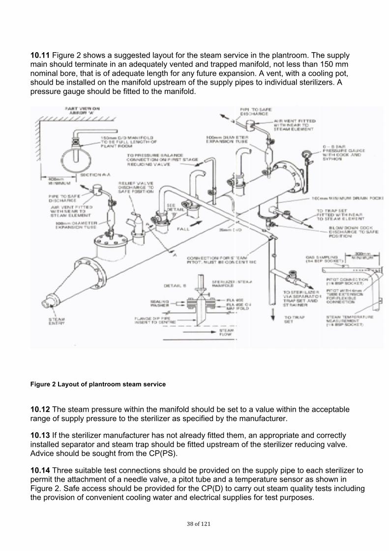
Consu
ltatio
n
draf
t
38 of 121
10.11 Figure 2 shows a suggested layout for the steam service in the plantroom. The supply main should terminate in an adequately vented and trapped manifold, not less than 150 mm nominal bore, that is of adequate length for any future expansion. A vent, with a cooling pot, should be installed on the manifold upstream of the supply pipes to individual sterilizers. A pressure gauge should be fitted to the manifold.
Figure 2 Layout of plantroom steam service
10.12 The steam pressure within the manifold should be set to a value within the acceptable range of supply pressure to the sterilizer as specified by the manufacturer.
10.13 If the sterilizer manufacturer has not already fitted them, an appropriate and correctly installed separator and steam trap should be fitted upstream of the sterilizer reducing valve. Advice should be sought from the CP(PS).
10.14 Three suitable test connections should be provided on the supply pipe to each sterilizer to permit the attachment of a needle valve, a pitot tube and a temperature sensor as shown in Figure 2. Safe access should be provided for the CP(D) to carry out steam quality tests including the provision of convenient cooling water and electrical supplies for test purposes.

Consu
ltatio
n
draf
t
39 of 121
10.15 Careful attention should be paid to the location of all pressure relief valves to ensure that the sterilizer is properly protected. Relief valves and their discharge pipes should be large enough to prevent the pressure in the supply pipe from the manifold rising to more than 10% above the design pressure for the manifold.
10.16 The discharge pipe should terminate outside the building in a safe, visible position not affected by frost. Any rising discharge pipe should be fitted with a drain at the lowest point to prevent the accumulation of condensate. A tell-tale pipe of narrow bore should be connected to the drain point and terminate inside the plantroom.
Materials 10.17 To meet the purity standard for sterilizers, parts in contact with steam entering the chamber should be constructed from low-carbon or stabilized stainless steel.
Dryness 10.18 Saturated steam is required for sterilization so that sufficient energy is transferred to the load upon condensation in order to achieve the required lethality. The dryness of the steam is therefore of vital importance; too little moisture carried in suspension may allow the steam to become superheated during expansion into the chamber and thus impair sterilization, while excess moisture may deliver insufficient energy to the surface of the load to be sterilized, and additionally may cause damp or wet loads and uneven temperature distribution.
10.19 Steam dryness is traditionally characterized by a “dryness fraction”, but this is not appropriate for sterilizers because the method of measurement is difficult and requires a constant flow of steam. The low-volume sampling technique described in the steam dryness test (see Section 2) cannot be regarded as measuring a true dryness fraction because the sample is taken from the centre of the steam supply pipe and condensate flowing along the pipe wall is not collected. Consequently the term “dryness value” is used, where 1.0 represents dry, saturated steam. This method is used to determine whether performance problems could occur during testing and routine production. It is suitable for sterilizer installations because control valves and pipe services fitted to the sterilizer considerably reduce the amount of condensate entering the sterilizer chamber such that the sample has a similar amount of free condensate to the steam in the chamber.
10.20 European Standards require that sterilizers be designed to operate with steam having a dryness value of not less than 0.9 when measured in accordance with the steam dryness test described in Section 2. For metal loads, the dryness value should not be less than 0.95. In practice, problems are unlikely to occur if the pressure reduction through the final pressure-reducing system is of the order of two to one.
10.21 Deviations from this specification are likely to cause the following problems:
a. wet loads, resulting from too low a dryness value;
b. superheating, resulting from either too high a dryness value before the pressure-reducing stage, or excessive pressure reduction through a valve or other restriction in the pipework (superheating may be severe if both conditions are present simultaneously);
c. difficulties with operation of the pressure-reducing system, resulting from a low pressure-reduction ratio, water hammer, water logging, dirt and other carry-over.

Consu
ltatio
n
draf
t
40 of 121
Excessive moisture 10.22 Possible causes of excessive moisture, where droplets of water are present in the steam and at the same temperature as that of the steam, are:
a. steam pipes or manifolds might be incorrectly sloped and drained;
b. the sterilizer might be supplied from an inadequately drained and vented “dead-leg” rather than a live steam main;
c. the pipework between the boiler and the sterilizer might be insufficiently insulated, causing excessive condensation of the supply steam.
10.23 If wet steam continues to be a problem, “priming” might be occurring in the boiler, causing water droplets to be delivered in the steam. Modern compact and high rated boilers and steam generators are particularly sensitive to the quality of feed-water treatment and are much more likely to prime than boilers of traditional design. Priming or foaming (which results in carry-over of the boiler water) can be caused by any of the following:
• incorrect feed-water treatment;
• boiler water level being set too high;
• forcing a boiler which needs internal cleaning;
• violent boiling under fluctuating load conditions;
• a high level (typically 2000 ppm) of TDS.
The relationship between water injection timing and steam generation should also be checked in order to reduce water slugging of the system.
Superheating 10.24 Superheated steam is an unsuitable medium for moist heat sterilization and can cause failure to sterilize, scorching of textiles and paper and rapid deterioration of rubber. Superheat conditions within the load and chamber may result from adiabatic expansion, exothermic reaction or both.
10.25 European Standards require that the superheat in free steam at atmospheric pressure should not exceed 25°C when measured by the superheat test.
10.26 Superheating caused by adiabatic expansion is usually the result of an excessive reduction in pressure through a throttling device, such as a pressure reducing system or a partially closed main steam valve. It is unlikely to be of significance in the circumstances normally encountered in hospital steam distribution systems, but superheating may arise if the main steam supply is dry, or the pressure is unusually high before the throttling device. This superheat can sometimes be avoided by the measures described in paragraph 10.12, which will reduce the dryness value of the steam at the inlet to the sterilizer pressure reducing system. The reduced pressure ratio will minimize the effect of the expansion through it.
10.27 Superheating arising from exothermic reaction may occur during sterilization as a result of rehydration of exceptionally dry hygroscopic material.

Consu
ltatio
n
draf
t
41 of 121
Non-condensable gases 10.28 Non-condensable gases (NCGs) are defined as gases that cannot be liquefied by compression under the range of conditions of temperature and pressure used during the sterilization process. Low levels of NCGs contained in steam supplied to sterilizers can markedly affect the performance of the sterilizer and the efficacy of the process, cause chamber overheat and lead to inconsistencies in the performance of air detectors and failure of the Bowie-Dick test (see Section 2). The major NCGs are air and carbon dioxide.
10.29 European Standards require that sterilizers be designed to operate with steam having a fraction of NCGs not exceeding 3.5% by volume of gases to steam that has been condensed when measured by the method described in the non-condensable gas test (see Section 2).
10.30 The main source of NCGs in the steam supply is the boiler feed-water and the level will be greatly influenced by the water treatment employed. In some cases a study by a water treatment specialist will be necessary. The study should cover analysis of the water, venting and the blow-down regime required in order to ensure protection of the boiler against corrosion whilst minimizing the entrainment of NCGs in the steam supply.
10.31 If anti-foaming agents and oxygen-scavenging agents (such as sodium sulphite) are used checks should be made to ensure that the dosages are accurate.
10.32 Water-softening treatment should be employed to prevent the formation of scale. A base-exchange softener will reduce scale but will also produce bicarbonate ions, which will break down into carbon dioxide in the boiler and give rise to an increase in NCG levels.
10.33 In order to drive off dissolved air, carbon dioxide and other NCGs in the boiler feed-water should be degassed before use by heating in a vented tank (a hot well). This will also break down bicarbonate ions, driving off further carbon dioxide. For the degassing to be effective, the temperature of the feed-water should not fall below 80°C at any time. The following measures should be adopted:
a. pipework returning condensate to the hot well should be well lagged to keep the condensate hot;
b. the amount of cold make-up water in the hot well should at no time exceed 15% (the rest being returned condensate) since new water will both lower the temperature and introduce further NCGs;
c. the water in the hot well should be kept well mixed; this may be achieved by locating the feed-water inlet on the opposite side of the tank from the outlet, and by arranging for the feed-water to be “sparged” from the inlet through a number of small openings.
10.34 In very hard water areas the level of NCGs may still be high despite these measures. Where this is the case, the feed-water should undergo dealkalisation treatment and the high temperatures in the hot well should be maintained. Treatment with filming amines is not permitted for sterilization applications.
10.35 Users should note that, even with a well-designed system, the level of NCGs can be affected by competing demands on the steam service. For example, where a central steam boiler supplies both a sterilizer unit and a laundry through the same distribution system, the level of NCGs in the steam at the sterilizer may rise when the laundry demand is high. This is the result of an influx of cold make-up water into the hot well. Paradoxically, in some installations the NCG

Consu
ltatio
n
draf
t
42 of 121
level may also rise when steam demand is low. In this case NCGs which would normally be removed by the laundry are being carried through to the sterilizer.
10.36 Some other causes of the presence of NCGs in the steam are as follows:
a. the boiler might be priming (see paragraph 10.23);
b. air might be being drawn into the system either through the boiler’s feed-pump glands or through a leak in the steam pipework between the boiler and the sterilizer;
c. steam pipework might be inadequately vented;
d. where NCGs are found in the sterilizer chamber during a production cycle:
i. there might be an air leak into the chamber;
ii. packaging materials, for example certain boxes, inks, adhesives, labels or trays, might be liberating gases.
Steam quality – responsibilities 10.37 The AE(D) should be able to advise the User on all aspects of the production and use of steam for sterilization.
10.38 The User should:
a. appreciate the nature of contaminants in steam supply (especially pyrogens), their possible adverse effects and their sources;
b. understand the requirements of legislation on medicinal products and medical devices as regards sterilization;
c. be familiar with the current and impending standards on steam sterilization and their implications for steam quality;
d. understand the difference between process steam, and steam as defined in BS EN 285 and BS EN ISO 17665 and the appropriate applications of each;
e. understand the rationale for the steam specification;
f. understand the engineering principles required for the delivery of steam and how they might be realised for mains steam, dedicated steam generators and sterilizers with internal reservoirs;
g. with appropriate advice, decide whether steam is required for any sterilizer unit and if so, what is the best means of achieving it;
h. after the required engineering work is complete, be satisfied that the chosen system is capable of supplying steam;
j. appoint a suitable laboratory and liaise with them regarding the analysis of steam and feedwater samples;

Consu
ltatio
n
draf
t
43 of 121
k. arrange for the steam supply to be formally validated;
l. on completion of the validation tests, confirm that the sterilizer is fit for use with the steam supply;
m. arrange for periodic maintenance of any steam generating and distribution plant under the User’s control;
n. arrange for periodic tests of the steam quality at intervals coinciding with periodic tests on the sterilizer.
10.39 The CP(D) should:
a. understand and be trained in the operation of the apparatus for taking samples of steam condensate for field analysis (Chapter 15);
b. be aware of the correct procedures for collecting, preserving and handling samples;
c. be trained in the measurement of electrical conductivity of water samples using a portable meter.
d. be trained and aware of the guidance in Chapter 17 if maintaining steam generators.
10.40 The Microbiologist (Decontamination) should be able to advise on all microbiological aspects of steam.

Consu
ltatio
n
draf
t
44 of 121
11.0 Contamination in steam supplies
Introduction 11.1 Recent years have seen a growing awareness of the need to improve the quality of steam used for sterilization, due in part to regulatory requirements for medicinal products and medical devices, but also by increasing concern about the potential harmful effects on patients of even minute quantities of contaminants on patients. BS EN ISO 17665 requires that impurities in any medium in contact with the medical device be known and limits of acceptability identified.
11.2 This chapter discusses the adverse effects that impurities in the steam supply can have on patients, equipment and the sterilizer itself. It identifies the products most likely to be susceptible to contamination and reviews the means by which various contaminants find their way into steam for sterilization.
Why does contamination matter? 11.3 Quality assurance in the manufacture of medicinal products and medical devices requires that the quality of the steam used in sterilization should be known and controlled. There are a number of specific contaminants known to have adverse effects and whose presence in steam is therefore undesirable.
Adverse effects on patients 11.4 Several contaminants are known to have adverse effects on patients.
a. Metals: Many of these are toxic (some are cumulative poisons) and therefore their presence is undesirable. Metals of particular concern include cadmium, lead, mercury and other heavy metals.
b. Organic compounds: Many of these are biologically active and therefore undesirable. The chief compounds of concern are filming amines and other chemicals that may be used in boiler treatment (see paragraph paragraph 11.29).
c. Microorganisms: This includes all pathogens and all Gram-negative bacteria (which are sources of pyrogens).
d. Pyrogens: These are bacterial endotoxins, predominantly derived from Gram-negative bacteria, which can cause severe reactions when administered intravenously (see paragraph 11.6).
e. Particulate material: Solid particles can lead to a number of adverse effects if injected into the body.
11.5 Pyrogens are of particular concern because, unlike other contaminants, there are no controls on the levels of pyrogens in public water supplies from which steam is generated. They are extremely heat-stable and are only destroyed after prolonged exposure to high temperatures (3 h at 180°C or 30 min at 250°C). They are not inactivated by any of the standard sterilization processes employed for medical devices and medicinal products. Control of pyrogens should be a priority for steam sterilization. There is detailed information about pyrogens in Chapter 18.

Consu
ltatio
n
draf
t
45 of 121
Adverse effects on materials 11.6 Contaminants in steam can have a damaging effect on the materials of load items and the sterilizer.
11.7 Reactive contaminants in the steam can cause corrosion or otherwise impair the longevity or function of the product. Reactions can occur when contaminants interact with the product directly, or indirectly (by interacting with materials that will subsequently come into contact with the product).
11.8 The steam also comes into direct contact with the internal surfaces of the sterilizer pressure vessel and associated equipment and instrumentation. Contaminants within the steam can react with the materials of construction and cause corrosion of the equipment or otherwise impair its longevity or function.
11.9 The reaction of steam with surfaces is affected by its pH. In general, steam of a low pH (acidic) will react with and dissolve metals. A pH of approximately 7 (neutral) is ideal and deviation towards alkaline (for example, to pH 8) is acceptable.
11.10 Contaminants of concern include the following:
a. Alkaline earth metals cause “hardness” which can lead to build-up of lime scale on load items, in the sterilizer chamber and in pipework. Most problems are caused by calcium and magnesium, and to a lesser extent strontium.
b. Iron, whether in metallic or ionic form, is corrosive to stainless steel.
c. Chlorides in the presence of oxygen lead to pitting corrosion and (to a lesser extent) crevice corrosion in stainless steel. The effects can be controlled by limiting the amount of oxygen in the feedwater (see paragraph 13.48).
d. Phosphates and silicates act to concentrate chloride ions and so promote their corrosive effects.
11.11 The materials used in the construction of load items and of the sterilizer itself will determine which contaminants are of greatest importance in each case. BS EN 285, the European Standard for sterilizers used to process medical devices, offers guidance on materials of construction suitable for all steam sterilizers.
11.12 Steam sampling systems should be constructed of materials that will not react with, and hence contaminate, the sample being collected.
Products vulnerable to steam-borne contamination 11.13 Any product can become contaminated if it comes into contact with the steam supplied to sterilizers. Contaminants in the steam are deposited on the product as the steam condenses during the heating-up stage. The amount of steam condensing, and hence the amount of contamination deposited, is proportional to the heat capacity of the load item, which in turn is proportional to its mass and the specific heat capacity of the material from which it is made. A massive metal item will therefore receive much more contamination than a light plastic item of similar size and shape heated to the same temperature.

Consu
ltatio
n
draf
t
46 of 121
11.14 The amount of contamination remaining at the end of the cycle will depend on how much condensate is retained at the surface of the product. Where condensate can drain freely from unwrapped items, a small fraction of the deposited contaminants will be held in a thin film of water and the total amount remaining when the film is evaporated will be proportional to the exposed surface area of the item. Where condensate is trapped in cavities or held in the packaging close to the surface, the amount of contamination retained will be proportionally greater.
11.15 Packaging materials for steam processes have a filtering effect that protects against contamination to some extent. Particulate matter is normally trapped on the outer wrapping (giving rise to discoloured packs) but smaller particles and all molecules will pass through with the steam and be transferred to the product as the steam condenses on it. Performance requirements for packaging materials can be found in BS EN 868.
11.16 Whether such contamination has any adverse effect depends upon the nature and intended use of the product. Vulnerable products are:
a. those that would permit direct transfer of contaminants to the patient, including:
i. medicinal products;
ii. porous goods such as dressings and swabs;
iii. surgical instruments and utensils;
b. those that would permit indirect transfer of contaminants to a patient, such as equipment used in pharmaceutical manufacturing (see paragraph 11.18);
c. those that would be impaired or inactivated by the presence of one or more of the possible contaminants, including:
i. certain medicinal products;
ii. laboratory products for in vitro diagnostic use.
11.17 Various items of equipment used in the manufacture of sterile pharmaceuticals and medical devices should be sterilized before use. It is important that during sterilization these items are not tainted with contaminants that can be transferred to the product being manufactured, whether that product is terminally sterilized or produced aseptically. Such items of equipment can include mixing vessels, filling heads, sterilization grade filters, filling lines, pipes and tubing for material transfer, connectors, and so on.
Sources of contamination 11.18 Contaminants delivered to the sterilizer in steam can arise from a number of sources:
a. contaminants present in the public water supply from which the steam is generated;
b. contaminants arising from treatment of the boiler feedwater;
c. contaminants arising in the distribution system carrying steam to the sterilizer.

Consu
ltatio
n
draf
t
47 of 121
Public water supply 11.19 While the quality of mains water supplies differs considerably from place to place, it can normally be relied upon to meet the minimum standards set out in The Water Supply (Water Quality) Regulations 2000, amended 2001. These specify more than 50 limits for a wide range of impurities including dissolved minerals, organic compounds and microorganisms.
11.20 There are no controls, however, on the amounts of atmospheric gases dissolved in mains water, all of which will be present in small and varying amounts. Air is the principal non-condensable gas that can impede steam sterilization and carbon dioxide and oxygen are important contributors to corrosion in boiler systems (see Section 1).
11.21 Most water companies use chlorine as a means of microbiological control. The disinfection effect of the chlorine can be largely lost, however, by the time the water reaches the point of use.
11.22 Water taken from the mains, and subsequently kept in storage tanks before use, can have significantly higher counts than the original mains water. In the summer months counts as high as 105–106 mL–1 are not uncommon. This may be of particular concern for sterilization since some 98% of the bacteria found in water supplies are reported to be Gram-negative bacteria, which are the predominant source of pyrogens. Further guidance may be found in HTM 04-01.
11.23 There are no requirements for suppliers to measure or control the level of pyrogens in mains water.
Boiler feedwater treatment 11.24 Further contaminants can be introduced either deliberately or inadvertently as a result of treatments applied to mains water before it can be used as boiler feedwater.
11.25 Base-exchange water softeners remove calcium and magnesium ions from the water and replace them with sodium ions (see paragraph 13.43). Sodium levels will therefore be raised in mains water softened by this method. The use of brine to regenerate the ion-exchange beds can temporarily raise the level of chloride.
11.26 Bacterial growth can occur in water softening, deionisation or reverse osmosis plant unless the manufacturer’s operating and maintenance procedures are strictly adhered to.
11.27 While bacteria will not survive the steam generating process, the pyrogens they produce could be delivered to the sterilizer.
11.28 Any chemicals added to the boiler water can be carried into the steam as contaminants either in droplets of water entrained in the steam during the evaporative process or as volatile components present as gases. Filming amines and other corrosion inhibitors and chemicals used to prevent corrosion in steam systems and boilers should only be used in concentrations that are proven not to pose a risk to patients via surgical instruments and medical devices they are in contact with or have an adverse effect on instruments or packaging. Concentrations of such chemicals should be carefully monitored to ensure safe limits are not exceeded.
Steam distribution system 11.29 Steam is chemically aggressive; the purer the steam the more reactive it is. Reaction with pipework and valves can lead to contamination of the steam with corrosion products such as magnetite (Fe3O4). Often in the form of fine particulates, these products are not readily removed by the strainers normally installed in steam services. Users of old installations have occasionally

Consu
ltatio
n
draf
t
48 of 121
noted black or reddish brown discoloration of packaging material by particles of magnetite shed from the walls of the steam pipes.
11.30 The hydrogen liberated by the formation of magnetite (400 mL for each gram of iron) can contribute appreciably to the amount of non-condensable gases in the steam delivered to the sterilizer, especially in new installations with long pipe runs.
11.31 Contamination is also likely to arise at points where water can collect, such as dead-legs, gauges and poorly maintained traps. Trapped water can result in rust, which can be shed into the steam as particles, and bacterial growth, which can lead to the formation of bio-films, which periodically generate high levels of contamination as they slough off.
11.32 Guidance on avoiding contamination from mains steam distribution systems can be found in paragraphs 13.20–13.24.
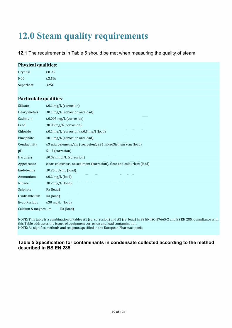
Consu
ltatio
n
draf
t
49 of 121
12.0 Steam quality requirements
12.1 The requirements in Table 5 should be met when measuring the quality of steam.
Physical qualities: Dryness ≥0.95
NCG ≤3.5%
Superheat ≤25C
Particulate qualities: Silicate ≤0.1 mg/L (corrosion)
Heavy metals ≤0.1 mg/L (corrosion and load)
Cadmium ≤0.005 mg/L (corrosion)
Lead ≤0.05 mg/L (corrosion)
Chloride ≤0.1 mg/L (corrosion), ≤0.5 mg/l (load)
Phosphate ≤0.1 mg/L (corrosion and load)
Conductivity ≤3 microSiemens/cm (corrosion), ≤35 microSiemens/cm (load)
pH 5 – 7 (corrosion)
Hardness ≤0.02mmol/L (corrosion)
Appearance clear, colourless, no sediment (corrosion), clear and colourless (load)
Endotoxins ≤0.25 EU/mL (load)
Ammonium ≤0.2 mg/L (load)
Nitrate ≤0.2 mg/L (load)
Sulphate Ra (load)
Oxidisable Sub Ra (load)
Evap Residue ≤30 mg/L (load)
Calcium & magnesium Ra (load)
NOTE: This table is a combination of tables A1 (re: corrosion) and A2 (re: load) in BS EN ISO 17665-‐2 and BS EN 285. Compliance with this Table addresses the issues of equipment corrosion and load contamination. NOTE: Ra signifies methods and reagents specified in the European Pharmacopoeia
Table 5 Specification for contaminants in condensate collected according to the method described in BS EN 285

Consu
ltatio
n
draf
t
50 of 121
13.0 Steam in practice
Introduction 13.1 This chapter discusses the principles by which steam conforming to the steam specification of Chapter 12 might be generated. It offers practical guidance on how to achieve steam standards for sterilizers supplied by mains steam and sterilizers supplied by a dedicated steam generator.
13.2 Full costings should be obtained when the relative merits of different steam supplies are being assessed. The cost of the testing required to demonstrate that a mains steam system can consistently produce steam might amount to a considerable fraction of the capital cost of a dedicated steam generator.
How steam is made 13.3 At first sight it might be surprising that there should be any contaminants in steam at all. Steam is generated by boiling, in which liquid water is converted into a gas. One might expect that any impurities in the water would be left behind, as in distillation, while pure steam in the form of H2O molecules was delivered to the sterilizer.
13.4 Boiling occurs at a temperature where evaporated water vapour has sufficient pressure to displace the water immediately below the surface to form bubbles of steam (at lower temperatures evaporation occurs only from the surface). The bursting of bubbles from the surface of the boiling water is accompanied by the ejection of small droplets of water. These droplets contain the same dissolved and suspended solids that are present in the water in the boiler. They are readily entrained in the flow of steam and thus carry contaminants to the sterilizer. Even if the water droplets subsequently evaporate, the contaminants will still be present in the form of solid particles.
13.5 Priming is a related phenomenon where significant quantities of the boiler water can sporadically be carried over into the steam. This is often as a result of a sudden increase in the demand for steam, which reduces the pressure above the water and effectively lowers the boiling point, so increasing the violence of bubbling. Having a level of water in the boiler that is too high can also lead to priming. Priming should be reduced by standard good operating practice, such as running the boiler at or near its maximum permissible pressure, using pressure sustain valves where demand causes a reduction in pressure in the distribution system and not in the boiler.
13.6 High concentrations of impurities in the boiler water also promote carry-over. They reduce the surface tension and so increase the agitation of the water surface. They can also cause the formation of a stable foam above the water surface leading to severe carry-over. Slugs of water are intermittently discharged from the boiler along with the steam, severely prejudicing the quality of the steam.
13.7 A crucial aspect of boiler design, therefore, is to ensure the best possible separation and removal of such entrained moisture.
Summary of requirements for steam

Consu
ltatio
n
draf
t
51 of 121
13.8 From the above considerations the requirements for generating steam can be summarized as follows:
a. feedwater should be as free as possible of contaminants, especially those specified for steam in Chapter 12;
b. the boiler should be designed to prevent water droplets being carried over into the steam;
c. the boiler should be operated to prevent foaming and priming;
d. the boiler and distribution system carrying steam from the boiler to the sterilizer should be resistant to corrosion.
13.9 A boiler system designed and operated to provide minimal carry-over of entrained water droplets will be able to maintain a low level of contaminants in the steam even where the quality of feedwater is poor.
13.10 Feedwater treatment might not be the decisive factor in the ability of a system to deliver steam. However, if the feedwater is of low quality, even small deviations from optimum operating conditions might result in large amounts of contaminants being carried over and delivered to the sterilizer. The designer of a robust steam supply should ensure that all the above requirements are met.
Steam from the mains steam supply 13.11 Experienced and monitored tests have shown that steam can be obtained from well designed, constructed and operated conventional boilers and distribution systems of the type found in most hospitals. If steam from this source is chosen, it is essential to demonstrate compliance and identify maintenance and boiler treatment regimes necessary for reproducibility.
13.12 Where a central supply does not deliver steam of acceptable standard, it is possible that the quality might be sufficiently improved by changes in operating practice and relatively minor engineering modifications. However, it is unlikely to be economical to embark on extensive remedial works such as the introduction of new feedwater treatment plant or the replacement of distribution pipework. It might be more cost-effective to install a dedicated steam generator solely to supply sterilizers (see paragraphs 13.26–13.49).
Boiler design and operation 13.13 The first step in assessing whether steam can be supplied from the mains is to examine the design and operation of the boiler plant.
13.14 An important consideration is the proportion of boiler feedwater that is fresh “make-up” water rather than steam condensate returned from the distribution system. In most large hospitals where steam is supplied centrally only a small fraction of the steam demand is due to sterilizers (which discharge most of their condensate to waste) and therefore the bulk of the condensate is returned to the boiler. This makes it more feasible to control the level of contaminants in the boiler. While the nature of the feedwater treatment is also of importance, the requirements for steam are unlikely to be achieved if the proportion of make-up feedwater exceeds 15%.

Consu
ltatio
n
draf
t
52 of 121
13.15 The level of total dissolved solids (TDS) in the boiler water is an important factor both in the prevention of foaming (see paragraph 13.6) and for the contaminants that might be present in the entrained water droplets. If steam is to be produced TDS levels should be below 2000 ppm. While some control of TDS concentration can be exercised by appropriate feedwater treatments, the boiler usually has a “blow-down” facility to allow accumulated sludge to be expelled from the bottom of the vessel. The water level gauge and TDS sensor element should also be blown down at regular intervals.
13.16 Filming amines, which are often added to feedwater to prevent corrosion of condensate return pipes, are toxic and are not acceptable for boilers supplying steam for sterilizers. If it is not possible for the boiler to be operated without filming amines, then another source of steam should be found.
13.17 While the boiler is unlikely to have been designed with the requirements of steam in mind, it should nonetheless have some means of preventing water being carried over into the steam. The chief precaution against carry-over is good practice in operating the boiler so that foaming and priming do not occur (see paragraph 13.5). Discussion with boiler-room staff will ascertain the degree to which operating procedures are successful in this regard.
13.18 Steam sampling points on the boiler are desirable and should be installed if they are not already fitted.
13.19 As the operational management of the steam supply will normally be outside the User’s control, the User should consult with the AP(D) to ensure that the boiler-room staff are aware of the principles of saturated steam for sterilization and that the necessary assurances will be met. The appointment of suitably qualified and trained boiler-room staff is an essential part of this process.
Distribution system 13.20 The distribution system also influences the quality of steam delivered to the sterilizer. The design of distribution systems suitable for the delivery of dry, saturated steam is considered in Chapter 10.
13.21 A purpose-built distribution system for steam would normally be constructed of stainless steel. However, when a large conventional installation has been in use for a number of months, a hard protective layer of oxide (magnetite) might have formed on the inside of the steam pipes (see paragraph 11.30). Providing the steam condensate is neutral or alkaline, this coat will remain intact and permit the use of the pipework for the distribution of steam. Acidic condensate in the presence of moist air, however, can break down the layer leading to corrosion, which might then be shed as contaminating particles.
13.22 It is important that the distribution system is free of dead-legs and other places where condensate might become trapped. During periods when the steam supply is off, such accumulations might become a focus of microbial growth. The trapped water might then be swept up into the steam when the supply is restored. Although the microorganisms might be killed by the steam, pyrogens will not be inactivated at the temperature of the steam and might be delivered to the sterilizer.
13.23 Other key points for a distribution system suitable for steam include:
a. correctly sized automatic air vents throughout the pipework distribution system to minimize the amount of air and other non-condensable gases delivered to the sterilizer;

Consu
ltatio
n
draf
t
53 of 121
b. properly sized and selected steam traps to remove condensate and air (if designed to do so);
c. steam pipeline velocities kept below 25 m s–1 to allow steam traps to remove entrained moisture effectively and to prevent condensate being drawn out of them;
d. steam separators near the steam take-off on boiler plant prone to generating wet steam;
e. strainers to protect control valves, steam traps, etc.
Quality assurance 13.24 Where a mains steam supply is found to be capable of meeting the steam specification, Users should assess whether the steam quality can be maintained under all operating conditions. There are several points to consider.
a. Frequent testing of the steam at the sterilizer will provide assurance that the steam specification is consistently met.
b. Competing demands on the steam service from other units in the hospital can degrade the steam quality at the sterilizer.
c. Steam quality is apt to vary through the year as the boiler room responds to changing seasonal demands.
d. An otherwise effective steam supply can quickly deteriorate if appropriate periodic maintenance is not carried out.
e. Arrangements should be made for the User to be warned of imminent engineering modifications, maintenance and changes in steam generation, distribution and operating practice. If changes are likely to be made without the User’s knowledge, the supply cannot be considered a reliable source of steam.
Steam from a dedicated generator 13.25 A dedicated steam generator, whether supplying one or several sterilizers, should be used where steam cannot be reliably obtained from the mains supply or for new installations. Since the bulk of the condensate from sterilizers is discharged to waste and not returned to the boiler, such generators might have to run on practically 100% make-up feedwater.
13.26 A dedicated system should therefore:
a. minimize the amount of non-condensable gases and other contaminants in the boiler feedwater;
b. prevent liquid water leaving the boiler and being delivered in the steam;
c. prevent microbial growth in any storage tank or pipework;
d. be constructed from materials resistant to corrosion and particle shedding, such as low-carbon stainless steel (type 316L).

Consu
ltatio
n
draf
t
54 of 121
The capacity of the generator should be sufficient to meet both maximum and minimum demands while still maintaining the requirements for dryness and non-condensable gases specified in paragraphs 16.5–16.20.
13.27 Steam sampling points should be fitted between dedicated generators and the sterilizer entry point so that steam quality tests can be performed.
Moisture separation 13.28 A steam generator should allow the entrained water droplets to be separated from the steam before it is delivered to the sterilizer. The baffles used in some conventional boilers are not normally adequate for this purpose, but good results have been obtained on experimental machines using cyclonic separators, which essentially spin-dry the steam by causing it to rotate at high speeds. Experience has shown that the fitment of a large plate type separator fitted in the main steam line can safely remove water carry over from the distribution system prior to the header. This will protect the loads as processed in the porous-load sterilizers.
13.29 The manufacturer will have measured the efficiency of moisture removal by spiking the feedwater with high levels of endotoxin (at least 103 EU mL–1) and testing samples of the steam for endotoxin levels by means of the LAL test (see Chapter 18). This work should be undertaken only by personnel with appropriate training and experience. Tests on an experimental steam generator have shown that reduction factors greater than 105 can be consistently achieved.
13.30 Adequate moisture removal should be maintained over the entire range of steam demand, typically up to 200 kg h–1 for each sterilizer.
Heating 13.31 A single 600 L porous-load sterilizer requires a steam generator capable of converting energy at a rate of up to 50 kW. A group of sterilizers will require a proportionately higher heating power.
13.32 Where existing sterilizers are supplied from a central boiler the ideal solution is to install a generator heated by mains steam. The steam generator is then effectively a steam-to-steam calorifier, in which the mains steam is used only to heat the feedwater and does not come into contact with the steam for the sterilizer. Primary steam requirements for this type of calorifier will normally be 300 kg h–1 for each sterilizer at a minimum pressure of 10 bar and operating on 100% condensate return. Where mains steam is not available, a small packaged boiler might be a convenient source of steam for heating, but should not itself be regarded as a source of steam.
13.33 Generators might be heated by electricity, but size for size, an electrically heated generator cannot match a steam-to-steam generator for heating power. The pressure in the boiler cannot be maintained at a high enough level to ensure adequate removal of droplets by the cyclonic method described above. Gas-fired heating is not recommended for stainless steel boilers.
Materials 13.34 The boiler and other parts of the generator that come into contact with feedwater or steam should be constructed of corrosion-resistant stainless steel (such as low-carbon 316L grade).

Consu
ltatio
n
draf
t
55 of 121
13.35 Pipework connecting the steam generator to the sterilizer should be also constructed in stainless steel. Since the generator can be sited close to the sterilizer, it is a false economy to re-use existing sections of the steam supply system.
13.36 While existing sterilizers should not be harmed by a carefully-designed steam system, steam-contact surfaces of iron, mild steel or copper should be avoided in new machines. In most cases this will require contact surfaces to be fabricated in stainless steel as specified in BS EN 285.
Feedwater treatment 13.37 Since there is no return of chamber condensate from the sterilizer, the quality of feedwater is crucial to the performance of a steam generator. It is especially critical for those generators that operate on a straight-through principle and have no reservoir of water within the boiler.
13.38 Water drawn from the public supply might be hard, that is containing significant concentrations of the salts of the alkaline earth metals (chiefly calcium and magnesium), and might also have traces of other contaminants that need to be removed. To assess the need for water treatment, Users should obtain an analysis of the mains water from the supply company providing a trend over a 12-month period. Under The Water Supply (Water Quality) Regulations 2000, amended 2001 such an analysis should be supplied to customers on request and free of charge.
Note: The Water Supply (Water Quality) (Scotland) Regulations 2001 apply in Scotland; Water Supply (Water Quality) (Northern Ireland) Regulations 2002 apply in Northern Ireland.
13.39 Although the stated water quality can be relied on most of the time, gross contamination of water supplies might occasionally occur due to engineering works and treatment failures.
13.40 Full water treatment consists of three stages:
a. softening (to remove scale-forming contaminants which might harm the boiler);
b. purification (to remove other undesirable contaminants);
c. degassing (to remove corrosive and non-condensable gases).
13.41 The need for softening treatment will depend on the hardness of the local water supply. Where the water is soft it might be possible to achieve the steam requirements without further treatment. In such cases Users should be aware that the quality of the steam will vary with the quality of the water supply, and that the quality of the steam should be frequently monitored to ensure that the steam specification is maintained.
13.42 In hard-water areas a base-exchange softening plant will normally be required. In this process calcium and magnesium ions are exchanged for sodium ions in a zeolite column (permutite process). The columns are periodically regenerated by flushing with brine (sodium chloride). The flushing should be carried out in accordance with the manufacturer’s instructions to prevent chloride ions being introduced into the softened water.
13.43 Microbial growth might occur in the columns unless the equipment is correctly operated and scrupulously maintained.
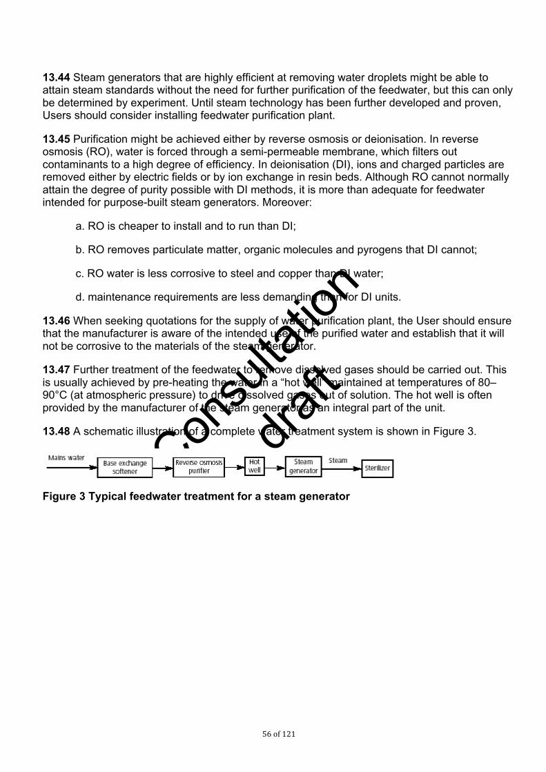
Consu
ltatio
n
draf
t
56 of 121
13.44 Steam generators that are highly efficient at removing water droplets might be able to attain steam standards without the need for further purification of the feedwater, but this can only be determined by experiment. Until steam technology has been further developed and proven, Users should consider installing feedwater purification plant.
13.45 Purification might be achieved either by reverse osmosis or deionisation. In reverse osmosis (RO), water is forced through a semi-permeable membrane, which filters out contaminants to a high degree of efficiency. In deionisation (DI), ions and charged particles are removed either by electric fields or by ion exchange in resin beds. Although RO cannot normally attain the degree of purity possible with DI methods, it is more than adequate for feedwater intended for purpose-built steam generators. Moreover:
a. RO is cheaper to install and to run than DI;
b. RO removes particulate matter, organic molecules and pyrogens that DI cannot;
c. RO water is less corrosive to steel and copper than DI water;
d. maintenance requirements are less demanding than for DI units.
13.46 When seeking quotations for the supply of water purification plant, the User should ensure that the manufacturer is aware of the intended use of the purified water and establish that it will not be corrosive to the materials of the steam generator.
13.47 Further treatment of the feedwater to remove dissolved gases should be carried out. This is usually achieved by pre-heating the water in a “hot well” maintained at temperatures of 80–90°C (at atmospheric pressure) to drive dissolved gases out of solution. The hot well is often provided by the manufacturer of the steam generator as an integral part of the unit.
13.48 A schematic illustration of a complete water treatment system is shown in Figure 3.
Figure 3 Typical feedwater treatment for a steam generator

Consu
ltatio
n
draf
t
57 of 121
14.0 Testing for compliance 14.1 This chapter discusses the testing regimes necessary for the initial validation of a steam supply for sterilization and for subsequent periodic testing. Methods for taking steam samples are given in this chapter and their analysis is discussed in paragraphs 15.39–15.63. Further information on steam, steam generators and their management can be found in Section 3 of this Part.
Where to take samples 14.2 To ensure a thorough quality assessment of the steam supply, water and steam samples should ideally be taken throughout the steam generating and distribution system from incoming water to steam at the sterilizer, though such extensive sampling will rarely be needed in practice. Examples of points at which samples may be taken include:
a. mains water, which after suitable treatment will be used as feedwater to the boiler;
b. treated water, which may include one or more distinct treatment stages. Samples should be taken from the inlet and outlet pipes as close as possible to the treatment plant. To monitor the various stages of water treatment samples should be taken after each stage;
c. feedwater, the water admitted to the boiler from the hot well, without any dosing treatments admitted simultaneously or separately to the boiler;
d. boiler water, the water in the boiler prior to blow-down;
e. boiler steam, the steam leaving the boiler;
f. steam for use in the sterilizer, the steam delivered to the sterilizer, sampled at the steam service pipe.
Testing of the total system can be costly and may only be required where major problems are experienced.
14.3 The sampling points should be chosen so that the samples obtained will allow the identification and quantification of any significant changes in contamination levels at each stage in the process. For example, sampling before and after a base-exchange water softener may reveal an increase in bacterial endotoxin levels from a contaminated ion exchange column. A full set of sampling points at strategic locations will allow such problems to be investigated with a minimum of disruption, even though most of them will rarely be used in routine operation. Guidance on the design and use of sampling points is given in paragraphs 15.3–15.7.
14.4 The design and construction of the system will determine how many sampling points would be of value. For a mains system supplying a large hospital, all the above points may be desirable. For a sterilizer with an adjacent, dedicated steam generator supplied from a simple treatment plant, fewer would be needed.
Validation and periodic testing 14.5 Validation tests should normally be carried out on the following occasions:

Consu
ltatio
n
draf
t
58 of 121
a. on initial validation of the steam-raising and distribution plant;
b. on initial validation of the sterilizers served by the steam plant;
c. on yearly testing or revalidation of the sterilizers;
d. when there is operational evidence that the steam quality may have deteriorated;
e. after any significant modification of the steam plant or its operation.
14.6 Periodic tests should be carried out during quarterly testing of the sterilizers.
14.7 As a minimum, samples for validation should include the feedwater and the steam for use in the sterilizer. Testing the steam without testing the water from which it is raised can lead to a false sense of security. For example, high levels of pyrogens in the feedwater will not necessarily produce contamination in the steam when the boiler is operating under loads that do not induce carry-over or priming. But during normal operation this could occur and contamination in the feedwater would require urgent investigation and remedial action.
14.8 Once a steam supply has been validated, periodic testing of steam quality will be necessary. Quarterly testing of electrical conductivity is recommended (see paragraphs 19.3–19.13), but the frequency will depend upon the particular application and the consistency of control established from historical data. Other tests might be necessary if one or more of the possible contaminants is critical for the process or product.
Mains steam supply 14.9 Formal validation should be carried out once the user is satisfied that the chosen system is capable of supplying steam and boiler-operating procedures have been established. Much exploratory testing may be required before this point is reached.
Validation test 14.10 The CP(D) should consult boiler room records to establish how the demand on the boiler varies through a typical working day (in a large hospital sterilizers are likely to contribute only a small fraction of this load). The object is to ensure that times of highest and lowest demand can be reliably identified so that representative steam samples can be taken.
14.11 It may take several minutes for steam produced in the boiler to arrive at the sterilizer, due to the large amount of steam contained within a mains distribution system. This means that the steam quality at the sterilizer might not be representative of the quality at the boiler. In particular, the steam in the pipes may have been generated at a time of less extreme demand and therefore be of higher quality, although if it has been standing in the pipes it is more likely to have been contaminated by the distribution system. CP(D)s should therefore ensure that the steam sample was generated when the boiler was operating at the appropriate level of demand, for example by flushing the plant room manifold pipework with fresh steam immediately before samples are taken. In practice, the samples should be satisfactory if the boiler demand has been steady for several minutes and remains steady while the flushing takes place and the samples are taken.
14.12 Two samples each of feedwater and steam at the sterilizer should be taken:
a. at a time of highest demand;

Consu
ltatio
n
draf
t
59 of 121
b. at a time of lowest demand.
14.13 Samples should consist of:
a. a full set of duplicate samples for laboratory analysis as described in paragraphs 15.19 to 15.25;
b. a field sample as described in paragraphs 15.8 to 15.18.
14.14 Where more than one sterilizer is supplied from the same steam manifold, steam samples should be taken at the sterilizer furthest downstream from the boiler. It is not necessary to sample the steam at each sterilizer.
14.15 Samples should be given a full laboratory analysis (see paragraph 15.39). The field sample should be tested for electrical conductivity on site as described in paragraphs 19.3–19.13.
14.16 If the steam samples fail the test, the feedwater analysis should be examined to determine whether the failure could be remedied by a simple adjustment of the treatment regime. If not, further samples may need to be taken at points other than those mentioned in paragraph 14.2 to establish where the problem originates.
14.17 When validation has been completed successfully, the mains supply may be used as a source of steam for sterilization although users should proceed with caution until sufficient experience has been gained to build confidence in the system. During the first year of steam operation, the validation tests should be repeated at intervals chosen to coincide with the peak variations in seasonal demand. This will provide further assurance that the system is capable of meeting the steam specification under all normal operating conditions. If any tests fail during this period corrective action should be taken and the tests repeated.
Periodic tests 14.18 Periodic testing of the steam supply should be carried out on an Annual basis to coincide with the tests scheduled for the sterilizer. Periodic testing of the feedwater is not necessary. The test should consist of a conductivity measurement of a field sample (see paragraphs 19.3–19.13) and the conductivity value should remain below the limit established during validation. Failure of the periodic test requires further investigation, normally by a full laboratory analysis of both feedwater and steam.
14.19 Additional tests may be required if problems are experienced with steam quality/contaminants. The advice of the AE(D) should be sought as to frequency of testing required in that case.
Dedicated steam generator 14.20 A dedicated steam generator supplying one or more sterilizers may not suffer competing demands from other equipment and may be more likely to be within the User’s control. Consistency of steam quality may therefore be demonstrated more readily than for a mains steam supply.
Validation test

Consu
ltatio
n
draf
t
60 of 121
14.21 Validation can normally be carried out as soon as the Contractor has installed the equipment and completed their own installation tests.
14.22 The CP(D) should first establish when the steam generator will be subject to the highest and lowest demand. Depending on the design of the steam plant, it is possible for either to constitute the worst-case conditions for carry-over of moisture. For example, a large plant designed to supply several sterilizers and relying on a cyclonic separator for removal of entrained water droplets may be inefficient at the lower velocities generated by a single sterilizer on light load.
14.23 The highest demand on the boiler usually occurs when all sterilizers are operating simultaneously. However the period of peak demand (steam admission into the chamber) is brief and it is difficult to synchronise the operating cycles so that the peaks coincide for long enough to allow a sample to be taken.
14.24 An alternative method is to vent steam from the relief valve on the plantroom manifold. Users should first ensure that the steam will be discharged to a safe position outside the building. The relief valve is designed to limit pressure in the system and therefore this action creates a demand on the boiler that is greater than the maximum demand of the sterilizers. If steam samples collected under these conditions comply with steam specification then it can be assumed that the generator will cope with the demand of the sterilizers. If not, the generator may still comply if loaded normally, and further testing will be required.
14.25 A third possibility is to install a discharge valve on the steam manifold designed to simulate the peak demand of all sterilizers operating at the same time.
14.26 The amount of steam contained within the distribution system will be small, the steam produced in the boiler will arrive at the sterilizer almost instantly, and the steam sample collected can be assumed to be representative of that created in the boiler.
14.27 Two samples each of both feedwater and steam at the sterilizer should be taken under conditions of highest demand.
14.28 Samples should consist of:
a. a full set of duplicate samples for laboratory analysis as described in paragraphs 15.19 to 15.25;
b. a field sample as described in paragraphs 15.8 to 15.18.
14.29 Where more than one sterilizer is supplied from the same steam generator, steam samples should be taken at the sterilizer furthest downstream. It is not necessary to sample the steam at each sterilizer.
14.30 Samples should be given a full laboratory analysis (see paragraph 15.39). The field sample should be tested for electrical conductivity on site as described in Chapter 19.
Periodic tests 14.31 Periodic testing of the steam supply should be carried out on an Annual basis to coincide with the tests scheduled for the sterilizer. Periodic testing of the feedwater is not necessary. The test should consist of a conductivity measurement of a field sample (see paragraph 19.3–19.13) and the conductivity value should remain below the limit established during validation. Failure of

Consu
ltatio
n
draf
t
61 of 121
the periodic test requires further investigation, normally by a full laboratory analysis of both feedwater and steam. Additional tests may be required if problems are experienced with steam quality/contaminants. The advice of the AE(D) should be sought as to frequency of testing required in that case. Failure of the periodic test requires further investigation, normally followed by a full laboratory analysis of both feedwater and steam.
14.32 Revalidation should be carried out once a year, to coincide with the yearly testing of the sterilizer.

Consu
ltatio
n
draf
t
62 of 121
15.0 Sampling 15.1 This chapter discusses methods for taking water and steam samples for both field and laboratory analysis.
15.2 There are two types of water and steam samples that should be taken: field and laboratory samples. Field samples will normally be taken and analysed by the CP(D) in the course of testing the sterilizer. Laboratory samples may be taken either by personnel from the receiving laboratory or by the CP(D) (if qualified).
Sampling points 15.3 Sampling is required in each part of the system where the composition of the water or steam might need to be confirmed, or where changes in composition might need to be determined. Sampling points should be designed and constructed to ensure that:
a. the sample taken is as nearly as possible representative of the water or steam in that section of the system;
b. the sample can be taken without contaminating it;
c. the sample can be taken safely.
15.4 When possible, samples should be taken from flowing rather than static parts of the system. For example, in sampling a tank the samples are best taken from the inflow or outflow pipes rather than the static reservoir.
15.5 Where boiler water is to be sampled the position of the sampling point should be chosen with care, giving consideration to the fact that the composition of water can vary considerably at different locations in the boiler. For boilers with forced circulation the sampling point is best located on the discharge side of the pump.
15.6 It is good practice to install coolers to ensure that representative boiler water samples can be taken safely.
15.7 Guidance on the design and construction of sampling points is given in BS 6068-6.7.
Sampling for field analysis 15.8 This method is suitable for taking steam and water samples to be tested for electrical conductivity during periodic tests. It should not be used for samples intended for laboratory analysis.
Apparatus 15.9 Figure 4 shows the apparatus connected to a pitot tube identical to the one specified for the steam quality tests in Chapter 16. The pitot is fitted to the steam supply pipe near the sterilizer. This standard pitot is not suitable for laboratory samples. Figure 5 shows an alternative pitot that may be used for all steam testing. If this pitot is used for field samples or the tests in Chapter 16, the ball valve, nipple and socket should be removed.

Consu
ltatio
n
draf
t
63 of 121
15.10 Steam is led through a length of polypropylene tubing and condensed as it passes through a bath of cold or iced water.
15.11 This apparatus is suitable for use for samples that are to be analysed immediately, such as for periodic tests for electrical conductivity. It is not suitable for samples intended for more sensitive analysis in the laboratory. It is also unsuitable for taking samples for pyrogen testing.
15.12 Steam pipework and sampling apparatus will be hot and adequate precautions should be taken against getting burnt. Thermal gloves and safety glasses should be worn.
Method 15.13 Use new polypropylene tubes for each test or series of tests. Clean the polypropylene sample bottle by rinsing well with distilled water. Detergents should not be used. Leave them to dry.
15.14 If the pitot is not already fitted, isolate the steam supply and vent the pipe of pressure. Fit the pitot tube into the pipe and secure the polypropylene tube to it with a clip.
15.15 Restore the steam supply and allow steam to vent through the polypropylene tube for at least 5 min to restore the steam service to its stable operating temperature. Ensure that the condensate drains freely. Close the steam valve.
15.16 Coil part of the tube into a sufficient number of coils to ensure condensation of steam, place it in the 8 L container and retain it in place. Fill the container with enough cold water (add ice if required) to immerse the coils.
15.17 Open the steam valve. The steam will condense in the coils and condensate will emerge from the end of the tube. Allow the first 50 mL of condensate to discharge to waste and then collect approximately 250 mL in the sample bottle.
15.18 Seal and label the bottle. The electrical conductivity should be measured promptly as described in paragraphs 19.3–19.13.

Consu
ltatio
n
draf
t
64 of 121
Figure 4 Steam sampling system for field analysis
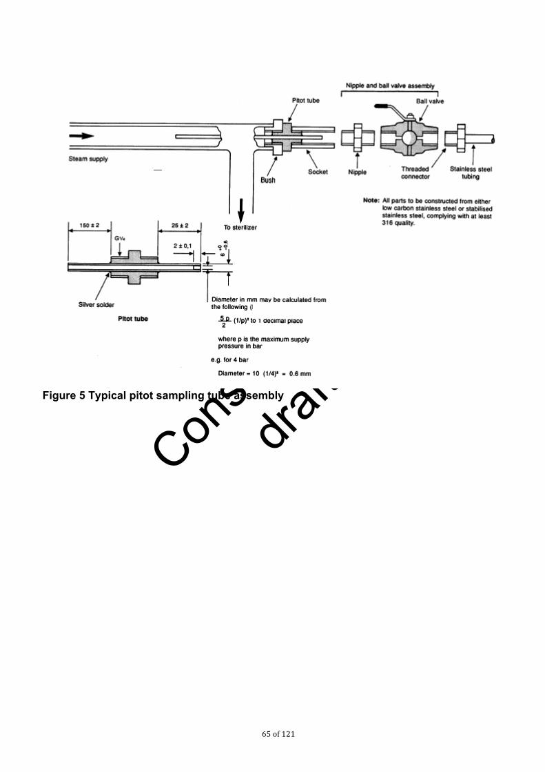
Consu
ltatio
n
draf
t
65 of 121
Figure 5 Typical pitot sampling tube assembly

Consu
ltatio
n
draf
t
66 of 121
Sampling for laboratory analysis 15.19 This method is suitable for taking all required samples, including those to be subjected to full laboratory analysis and the test for pyrogens.
Apparatus 15.20 The apparatus is shown in Figure 6. All components, including the condenser and valves, are constructed in 316L stainless steel. The tubing is made in short sections connected by compression joints to form the required length and configuration. The sections are short enough to allow each element to be thoroughly cleaned, sterilized and depyrogenated before use.
15.21 The standard pitot used with the field sampling apparatus described above is not designed to take compression fittings and so cannot be used with this apparatus. It should be replaced with the modified pitot and ball valve shown in Figure 6.
15.22 The apparatus is suitable for taking samples for all the determinands of interest. It may be used for steam condensate or water samples throughout the steam-raising system. In theory there is a risk of some contamination of the sample from metals that could be extracted from the stainless steel, but the grade of steel chosen is no more reactive than those used in the construction of steam pipes and equipment. If, for whatever reason, the steam reacts with the sampling apparatus it will also have reacted with the installed system.
Method 15.23 Clean and prepare sample bottles and stainless steel components according to the instructions from the receiving laboratory. Normally, two sets will be used for steam samples and one for control samples. Ensure that the bottles are labelled as described in paragraph 15.36.
15.24 Open the valve on the pitot and allow steam to vent through the cooler for at least 5 min before turning on the cooling water. The steam will condense in the coil and condensate will emerge from the end of the tube. Allow the first 50 mL of condensate to discharge to waste and then collect samples in the first two sets of bottles.
15.25 Fill the third set of bottles with Water for Injection BP and preserve and analyse this in the same manner as the two sets of steam samples.
Note: These negative control samples provide evidence that the choice of container, cleaning system and preservative is appropriate.
Handling of samples for laboratory analysis 15.26 It is important that the physical, chemical and biological properties of water and steam samples remain stable from when they are sampled until they arrive at the laboratory for analysis. The conditions in which the sample should be kept are determined by the contaminants for which the water is to be tested. The material of the sample container is also important since it may interact with substances in the water; plastic is suitable for some parameters, glass for others.
15.27 General guidance on these points is given below; more specific advice is in BS 6068-6.3. The laboratory carrying out the analysis will normally provide all the necessary containers, preservatives and labels with full instructions for their use.

Consu
ltatio
n
draf
t
67 of 121
Figure 6 Steam sampling system for laboratory analysis

Consu
ltatio
n
draf
t
68 of 121
Containers 15.28 There is no single material suitable for containing samples with all relevant contaminants. Containers may be made from polyethylene, polystyrene, polypropylene, glass or borosilicate glass. The receiving laboratory will normally supply the appropriate containers with full instructions for their use.
15.29 Each type of container requires a different cleaning procedure to ensure samples are not contaminated by residues. The instructions from the receiving laboratory should be followed.
15.30 The laboratory’s instructions on filling and closing the bottles should be followed. Most bottles should be filled to the brim and then stoppered or capped to ensure that as little air as possible remains above the sample. A small air space should be left above samples to be frozen.
Sample preservation 15.31 The purpose of preservation is to maintain the concentration and state of the contaminant of interest unchanged from when the sample was taken to arrival in the laboratory.
15.32 There are many possible interactions that would adversely affect the sample. The contaminant of interest might:
a. polymerise or if already a polymer, depolymerise;
b. react with other constituents of the sample;
c. react with atmospheric oxygen or carbon dioxide becoming dissolved in the sample;
d. be consumed, modified or be produced in higher concentrations by microorganisms growing in the sample;
e. react with, or be adsorbed or absorbed by, the material of which the container is constructed.
15.33 The sample and the extent and nature of any contaminants present, will determine which reactions and changes may occur. The more contaminated a sample, the more likely it is that changes will occur. In addition, the temperature during transport and storage, exposure to light, the container material and any special precautions used in the its preparation, and the elapsed time before analysis will all affect reactions and changes.
15.34 While it is desirable for all samples to be cooled (normally at 2–5°C) some will require the addition of an acid preservative and others will need to be frozen. The receiving laboratory will specify the preservative treatment for each container and supply suitable reagents where necessary.
15.35 Few preservative treatments for the contaminants specified for steam are valid for more than 24 hours and some for a much shorter time. Prompt despatch and analysis are therefore essential.
Identification of samples

Consu
ltatio
n
draf
t
69 of 121
15.36 Each container should be unambiguously labelled with a water-resistant label at the time of sampling. The laboratory will supply suitable labels and instructions. The information to be recorded should include:
a. the establishment at which the sample was taken;
b. the date and time at which the sample was taken;
c. the name of the person taking the sample;
d. clear identification of hazardous materials present (e.g. acids used as a preservative) plus either:
i. an unambiguous reference number for contemporaneous notes of the information in (i);
ii. the sampling point;
e. the nature of the sample (e.g. condensed steam);
f. the determinand(s) for which the sample is to be analysed;
g. any preservative treatment;
h. notes on any observations pertinent to the analysis, such as an event not in accordance with the sampling procedure that might affect the analysis.
Packaging and transport 15.37 The samples should be packaged securely in containers providing suitable protection from breakage or external contamination during transport. The containers should be kept as cool as possible during transport. For transporting small quantities of samples, domestic cool boxes provide suitable protection and cooling.
15.38 The transport container should be accompanied by a list of the samples being sent. A duplicate of this list should be retained the AP(D) and/or User The list should be sufficiently comprehensive to allow confirmation of the identity of each sample in the consignment.
Analysis of samples 15.39 This section discusses the means by which a sample of steam condensate may be analysed for compliance with the steam specification. The tests are equally suitable for testing samples of steam or water from elsewhere in the steam supply system, provided the limitations of the pharmacopoeial tests are understood.
Testing of samples 15.40 To determine whether a steam sample conforms with the steam specification it is necessary to carry out tests for all the determinands listed in BS EN ISO 285:2006.
15.41 Laboratories invited to carry out these tests should be accredited to a recognised standard.

Consu
ltatio
n
draf
t
70 of 121
Reporting of results 15.42 The report obtained from the laboratory for each test should contain the following information:
a. the exact identity of the water sample;
b. the date and time the sample was received;
c. the date and time at which the test was commenced;
d. the storage conditions if b) and c) are not the same;
e. the determinand for which the sample was analysed;
f. for non-quantitative tests, a statement as to whether the result complies with specification;
g. for quantitative tests:
i). the numerical value expressed in the unit specified for each of the duplicate determinations;
ii. the mean of the results of the duplicate determinations and the uncertainty that might be associated with the final result;
h. a description of any pre-treatment of the sample;
j. a description of the method used, including reference to specific items of equipment, calibration standards, etc;
k. any deviations from the method or other facts that might reasonably be expected to influence the result obtained; these should be signed both by the analyst responsible for carrying out the determinations and the analyst or quality controller responsible for checking the report.
15.43 For any given determinand there will usually be several methods that are suitable and cover the range of concentrations of interest. The choice of method should be determined by factors including availability of equipment, previous experience with the method, cost, and sensitivity to interfering substances that might be present. Consideration should be given to:
a. the limit of detection, which should be lower than the specified limit for the contaminant;
b. the accuracy of the method, which is of particular importance in observing changes in quality;
c. the likely presence of interfering substances in the samples to be tested.
Comments on the tests 15.44 There are several ways in which numerical results from any given analysis may be presented. The user should specify that the results are quoted in the units used in the “clean-steam” specification in BS EN 285 so that the sample can readily be compared with the specification.

Consu
ltatio
n
draf
t
71 of 121
15.45 The following sections give background information on interpreting the results of some of the steam tests and explains the relationships between them.
15.46 The requirements for steam are stated in Chapter 12, Clause 12.1

Consu
ltatio
n
draf
t
72 of 121
16.0 Physical steam quality tests 16.1. A continuous supply of saturated steam is required for steam sterilization. Too high a level of non-condensable gases will prevent the attainment of sterilizing conditions; too little moisture carried in suspension can allow the steam to become superheated during expansion into the chamber, while excess moisture can cause damp loads.
16.2 For all physical steam quality tests, the steam should be sampled from the steam service pipe to each sterilizer. The measurements are taken during a period of maximum steam demand, when steam is first admitted to the sterilizer chamber.
16.3 Silicone rubber tubing is porous to steam and should not be used to carry steam in these tests.
16.4 Steam pipework and sampling apparatus will be hot and adequate precautions should be taken against getting burnt. Thermal gloves and safety glasses should be worn.
Non-condensable gas test 16.5 This test is used to demonstrate that the level of non-condensable gases in the steam will not prevent the attainment of sterilization conditions in any part of the load. Possible sources of non-condensable gases are discussed in paragraph 10.30. The method described should not be regarded as measuring the exact level of non-condensable gas, but as a method by which the provision of acceptable steam quality can be demonstrated.
Apparatus 16.6 The apparatus is shown and described in Figure 7. All sizes are nominal. Alternative commercially-available versions of this may be used. Robust apparatus should lead to consistent result-gathering. When using commercially-available test units, correlation between the standard method and the alternative method should be established. For example, it may be necessary to ensure that the temperature in the container remains above 65°C during the test in order to avoid dissolution of carbon dioxide. The flow rate may also need to be adjusted to ensure that 200 mL of condensate is collected over the whole of the air-removal stage.
Method 16.7 Connect the needle valve to the steam service pipe as shown in Figure 7. When performing this test the pitot tube used for the superheat and dryness tests should not be connected.
16.8 Assemble the apparatus so that condensate will drain freely from the long rubber tube into the sampling pipe. Copper or stainless steel tubing may also be used.
16.9 Fill the container with degassed cold water, preferably condensate, until it overflows. Fill the burette and funnel with cold water, invert them and place them in the container. Draw out any air that has collected in the burette.
16.10 With the steam sampling pipe out of the container, open the needle valve and allow steam to purge the air from the pipe. Place the pipe in the container, locate the end within the funnel, and add more cold water until it flows through the overflow pipe.

Consu
ltatio
n
draf
t
73 of 121
16.11 Place the empty measuring cylinder under the container overflow.
16.12 Adjust the needle valve to allow a continuous sample of steam into the funnel sufficient to cause a small amount of steam hammer to be heard. Ensure that all the steam is discharged into the funnel and does not bubble out into the container. Record the setting of the needle valve. Close the valve.
16.13 Draw out any air present in the burette; ensure that the container is topped up with cold water and that the measuring cylinder is empty.
.
Figure 7 Apparatus for non-condensable gas test
16.14 Ensure that the sterilizer chamber is empty except for the usual chamber furniture. Select and start the operating cycle.
16.15 When the steam supply to the chamber first opens, open the needle valve to the previously recorded setting, allowing a continuous sample of steam into the funnel sufficient to cause a small amount of steam hammer to be heard.

Consu
ltatio
n
draf
t
74 of 121
16.16 Allow the steam sample to condense in the funnel. Any non-condensable gases will rise to the top of the burette. Overspill formed by the condensate and the water displaced by the gases will collect in the measuring cylinder.
16.17 When the temperature of the water in the container reaches 70–75°C, close the needle valve. Record the volume of gas collected in the burette (Vb) and the volume of water collected in the measuring cylinder (Vc).
16.18 Calculate the fraction of non-condensable gases as a percentage as follows:
Fraction of non-condensable gases = 100 x (Vb/Vc).
Results 16.19 The test should be considered satisfactory if the fraction of non-condensable gases does not exceed 3.5%.
16.20 The test should be carried out twice further to check consistency. If the results of the three tests differ significantly, the cause should be investigated before proceeding further.
Superheat test 16.21 This test is used to demonstrate that the amount of moisture in suspension with steam from the service supply is sufficient to prevent the steam from becoming superheated during expansion into the chamber. The test assumes that the steam supply pressure is nominally 4.0 bar gauge. If the supply pressure differs from this it might be necessary to amend the acceptance criteria accordingly.
16.22 The method described here uses a low-volume sample, continuously taken from the centre of the steam service pipe. The level of superheat determined by this method cannot be regarded as indicative of the true condition of the steam in the pipe since condensate flowing along the inner surface is not collected. However, devices designed to separate free condensate are incorporated into the steam delivery system to the chamber and therefore the level determined by this method is representative of steam conditions likely to prevail within the chamber during the plateau period.
16.23 This test should normally follow a satisfactory test for non-condensable gases.
Apparatus 16.24 A pitot tube is shown in Figure 8. The rest of the apparatus is shown and described in Figure 9.

Consu
ltatio
n
draf
t
75 of 121
Figure 8 Pitot tube
NOTE: change “bar” to kPa and the numbers to “up to 400”, “up to 500” and “up to 800”
Figure 9 Apparatus for superheat test
Method 16.25 Fit the pitot tube concentrically within the steam service pipe as shown in Figure 8.
16.26 Fit the sensor entry gland to the steam service pipe. Insert one of the sensors through the gland and position it on the axis of the pipe.

Consu
ltatio
n
draf
t
76 of 121
16.27 Insert the second sensor through the gland in the expansion tube and position it on the axis of the pipe. Wrap lagging around the expansion tube. Push the tube on to the pitot.
16.28 Ensure that the sterilizer chamber is empty except for the usual chamber furniture. Select and start the operating cycle.
16.29 From the measured temperatures, record the temperature in the steam service pipe (for use in the dryness test) and in the expansion tube (Te) when the steam supply to the chamber first opens. Calculate the superheat in °C from the following equation: Superheat = Te – T0, where T0 is the boiling point of water at local atmospheric pressure.
Results 16.30 The test should be considered satisfactory if the superheat measured in the expansion tube does not exceed 25°C.
Dryness test 16.31 The accurate measurement of the percentage of moisture content in the steam is difficult, and the traditional methods, where constant steam flow is required, are not suitable for sterilizers. This test should be regarded not as measuring the true content of moisture in the steam, but as a method by which the provision of acceptable steam quality can be demonstrated. Possible sources of excessive moisture are discussed in paragraphs 10.22–10.23.
16.32 The test is carried out immediately after the superheat test.
Apparatus 16.33 A pitot tube is shown in Figure 8. The apparatus is shown and described in Figure 10. All sizes are nominal.
16.34 A laboratory balance capable of weighing a load up to 2 kg with an accuracy of 0.1 g or better.
Method 16.35 If it is not already fitted, fit the pitot tube concentrically within the steam service pipe as shown in Figure 10.
16.36 If it is not already fitted, fit the sensor entry gland to the steam service pipe. Insert a temperature sensor through the gland and position it on the axis of the pipe.

Consu
ltatio
n
draf
t
77 of 121
Figure 10 Apparatus for dryness test
16.37 Connect the rubber tube to the longer of the pipes in the stopper, place the stopper in the neck of the vacuum flask, weigh the whole assembly and record the mass (M1).
16.38 Remove the stopper and tube assembly and pour 650 ± 50 mL of cold water (below 27°C) into the flask. Replace the stopper and tube assembly, weigh the flask and record the mass (M2).
16.39 Support the flask close to the pitot and ensure that the rubber tube and flask are protected from excess heat and draughts. Do not connect it to the pitot tube yet.
16.40 Introduce the second temperature sensor through the shorter of the two pipes in the stopper and into the water in the flask. Record the temperature of the water in the flask (T0).
16.41 Ensure that the sterilizer chamber is empty except for the usual chamber furniture. Select and start the operating cycle.
16.42 When the steam supply to the chamber first opens, connect the rubber tube to the pitot discharge and wrap lagging around it. Arrange the rubber tube to permit condensate to drain freely into the flask. Record the temperature in the steam service pipe (T0).
16.43 When the temperature of the water in the flask is approximately 80°C, disconnect the rubber tube from the pitot, agitate the flask so that the contents are thoroughly mixed and record the temperature of the water (T1).
16.44 Weigh the flask and stopper assembly and record the mass (M3).
16.45 The initial mass of water in the flask is given by Mw= M2–M1.

Consu
ltatio
n
draf
t
78 of 121
16.46 The mass of condensate collected is given by Mc= M3–M2.
16.47 Calculate the dryness value of the steam from the following equation:
T0 = initial temperature of the water in the flask (°C);
T1 = final temperature of the water and condensate in the flask (°C);
Ts = average temperature of the steam delivered to the sterilizer (°C);
Mw = initial mass of water in the flask (kg);
Mc = mass of condensate collected (kg);
L = latent heat of dry saturated steam at temperature T s (kJ kg–1).
0.24 kJ kg–1 = Effective heat capacity of the apparatus
Results 16.48 The test should be considered satisfactory if the following requirements are met:
a. the dryness value is not less than 0.95 unless only textile loads are being processed in which case 0.90 is permissible.
b. throughout the operating cycle, the temperature measured in the steam service pipe is within 3°C of that measured during the superheat test.

Consu
ltatio
n
draf
t
79 of 121
17.0 Operation and maintenance of steam generators
Introduction 17.1 Steam generators are steam boilers and are subject to the Pressure Systems Safety Regulations 2000, amended 2001.
17.2 Users should ensure that operation and maintenance of the generator is carried out correctly, both to ensure safety and also to maintain the quality of the steam.
17.3 Steam generators are subject to a written scheme of examination for pressure vessels.
17.4 Guidance on the design, maintenance, testing and operation of steam generators can be found in HSE Guidance Note PM 5, ‘Automatically controlled steam and hot water boilers’.
17.5 The advice of the boiler manufacturer about water supply, water treatment, blowing down and other operational practices should be strictly observed.
17.6 Failure to provide adequate supervision, with consequential inadequate control of water quality and insufficient blow-down, has resulted in such severe corrosion of steam generators that in some cases internal parts have collapsed and operators have been put in danger.
Operation 17.7 A risk assessment should be undertaken to establish the level of supervision required. While it is not acceptable for steam generators to be left continuously unattended, it is not necessary for an operator to be present at all times. The amount and frequency of attention necessary in each case will depend largely on the nature of the water supply, water treatment arrangements and the intensity of use. The operator, who can also be the sterilizer operator, should be adequately trained.
Maintenance 17.8 Because there is little condensate return to these steam generators, their feedwater is usually almost 100% make-up, and as a result the concentrations of dissolved and suspended solids in the boiler water quickly build up to very high levels. Such boilers are provided with a “blow-down” facility to expel deposits of sludge from the bottom of the boiler. It is essential that an effective blow-down regime is established and adhered to. There are three possibilities:
a. continuous blow-down – sludge is expelled continuously;
b. automatic intermittent blow-down – sludge is expelled automatically under the control of a timer or conductivity device;
c. manual intermittent blow-down – sludge is expelled manually under the control of the operator.

Consu
ltatio
n
draf
t
80 of 121
17.9 With manual blow-down there is a risk of affecting the steam quality if this is undertaken at a time when there is a high demand for steam. For this reason manual blow-down should be undertaken at times of light load, preferably when none of the sterilizers are operating. Continuous and automatic blow-down systems should be carefully managed to ensure they do not affect steam quality.
17.10 Guidance on blow-down can be found in HSE Guidance Note PM 60, ‘Steam boiler blow-down systems’ (PM 60).
17.11 Generator vessels constructed from stainless steel will be subject to the same risk of stress-corrosion cracking encountered in stainless steel sterilizer chambers (see Section 4). To minimize the risk, the manufacturer’s guidance on feedwater quality should be followed.
17.12 A record of all tests and maintenance should be kept in the machine’s plant history file.

Consu
ltatio
n
draf
t
81 of 121
18.0 Pyrogens
Bacterial endotoxins 18.1 Bacterial endotoxins are a group of compounds, derived predominantly from Gram-negative bacteria, which give rise to high temperatures and fever-like reactions when injected into man and other mammals. This febrile reaction is referred to as pyrexia, and compounds that can cause this reaction when injected are known as pyrogens.
18.2 Bacterial endotoxins are not the only pyrogenic compounds but they are by far the most common and are also of the greatest significance in sterile product manufacture.
18.3 The majority of bacterial endotoxins causing a pyrogenic reaction are lipo-polysaccharides (LPS) from the outer membrane of Gram-negative bacteria.
18.4 Organisms other than Gram-negative bacteria can give rise to endotoxins. For example fragments of the cell wall peptidoglycan from haemolytic Streptococci produce a similar pyrogenic reaction.
18.5 Bacterial endotoxins are extremely heat-stable and are only destroyed after prolonged exposure to high temperatures (3 h at 180°C or 30 min at 250°C). They are not destroyed by any of the sterilization processes commonly employed for medical devices and medicinal products.
Clinical significance 18.6 In small doses the injection of endotoxins causes pyrexia (fever), transient leukopenia followed by leukocytosis, hyperglycaemia, haemorrhagic necrosis of certain tumours, abortion, altered resistance to bacterial infection, various circulatory disturbances and vascular hyperreactivity to adrenergic drugs. When injected in larger amounts endotoxins cause shock, usually accompanied by severe diarrhoea; absorption of endotoxin from the bowel is a major cause of terminal irreversibility in haemorrhagic shock.
18.7 Endotoxins appear to cause pyrexia, not directly but through an endogenous pyrogen released from polymorphonuclear leukocytes.
18.8 Endotoxins are generally assumed to play a large role in the vascular, metabolic, pyrogenic and haematalogic alterations that occur in severe Gram-negative infections but the evidence is indirect since, unlike most bacterial exotoxins, no specific protective antibody is available.
18.9 Subcutaneous injection of microgram quantities of endotoxins produces a mild inflammatory reaction but, when the injection is repeated with the same or a different endotoxin 24 h later, the originally injected site becomes haemorrhagic within a few hours. This reaction (the Shwartzman reaction) is accentuated by the presence of cortisone.
18.10 Many sterile medical devices are intended for use on wounds where the dermis might have been breached. The sterile product might thus come into direct contact with the vascular system and if endotoxins are present might cause a pyrogenic reaction.
Detection and measurement
Consu
ltatio
n
draf
t
82 of 121
18.11 The classic method of detection of pyrogens in pharmaceutical products is by measurement of the temperature rise in rabbits to which the substance has been administered. This method does not readily permit assay of the amount of endotoxin present. However, it is sensitive to all pyrogenic substances, whether or not they are bacterial endotoxins.
18.12 In-vitro assay, which depends on the gelation of extracts of lysed blood cells of the horseshoe crab Limulus polyphemus, can be used quantitatively and will detect picogram quantities of lipopolysaccharide (endotoxin) in the so-called LAL test (Limulus amoebocyte lysate). A modification of the LAL test to provide a chromogenic test has been made, which allows reading of the endotoxin concentration by spectrophotometry. A turbidimetric method, which requires dedicated capital equipment, is also available as a quantitative method. Sensitivities as low as 0.001 EU mL –1 are available.
18.13 There is considerable variability in endotoxins derived from different bacterial species and it is difficult to set limits of permissible amount in terms of mass per unit volume. The US Food and Drugs Administration devised a unit of potency, the endotoxin unit (EU), to overcome this problem. The units are related to the endotoxin derived from Escherichia coli assigned by comparison with a USP reference endotoxin. The 1st International Standard for Endotoxin, established in 1986, consists of lyophilized endotoxin from E. coli 0113:H10:K(-)ve with trehalose (normally supplied in ampoules containing 14,000 EU). This – or another suitable preparation (such as the European Pharmacopoeia Biological Reference Preparation), the activity of which has been determined in relation to the International Standard using a gelation method – permits standardisation of the sensitivity of the lysate.
Generation of bacterial endotoxin 18.14 Endotoxins arise, almost without exception, from the cell wall of Gram-negative bacteria. This is present both on the surface of the living bacteria and as persistent fragments of dead bacteria. As previously noted the endotoxins are thermally very stable.
18.15 Gram-negative bacteria include a wide range of organisms, for example:
a. the sheathed bacteria e.g. Sphaerotilus spp which are large rods in a mucilaginous sheath found anchored to the substrate in running water (also called sewage fungus);
b. some 17 genera of budding or stalked bacteria such as Caulobacter;
c. the aerobic rods and cocci which include: Pseudomonas spp, which are ubiquitous; Xanthomonas spp, common plant pathogens; Halobacterium spp, which live in saturated brine; Brucella spp, etc;
d. the facultative anaerobes: Escherichia, indicator of faecal contamination; Salmonella, Shigella, intestinal pathogens; Erwinia, plant pathogen; Enterobacter, Serratia, Proteus, soil and aquatic; Vibrio, commonly marine aquatic;
e. the obligate anaerobes of the family Bacteroidaceae, Bacteroides, Fusobacterium.
18.16 These, or any other Gram-negative species, will inevitably give rise to endotoxins. However there are other organisms, such as haemolytic Streptococci, where the cell wall peptidoglycan produces the same reaction as endotoxins from Gram-negative bacteria.

Consu
ltatio
n
draf
t
83 of 121
18.17 The quantity of endotoxin produced per cell varies from about 4 femtograms (fg) in bacteria growing in very pure water to as much as 16 fg for those grown under nutrient-rich conditions. For E. coli, 0.03 EU mL–1 corresponds to approximately 0.003 ng per mL of endotoxin. Allowing that each cell produces approximately 6 fg of endotoxin then 500 bacteria per mL would give rise to 0.03 EU mL–1.
18.18 None of the sterilization processes used routinely for the preparation of pharmaceuticals, medical devices or surgical instruments will destroy or remove endotoxins once they are present. The only method of control therefore is to prevent the growth of significant numbers of Gram-negative bacteria within the product or in any component or material that directly comes into contact with it.
18.19 Gram-positive bacteria, with the exceptions noted above, do not produce endotoxins. The Gram-positive bacteria include organisms such as the family Micrococcaceae, which contains the genera Staphylococcus and Micrococcus, and the spore formers of the genera Bacillus and Clostridium. It is among these organisms that those species most resistant to radiation and thermal sterilization are found.
Regulatory requirements 18.20 Pharmacopoeial specifications for water include several different grades of which the two principal grades are Purified Water and Water for Injections (WFI).
18.21 In the European Pharmacopoeia (EP) WFI is required to be prepared from potable water or purified water “by distillation in an apparatus of which the parts in contact with the water are of neutral glass, quartz or suitable metal and which is fitted with an effective device to prevent the entrainment of droplets. The apparatus should produce water free from pyrogens and to ensure this correct maintenance is essential. The first portion of the distillate obtained when the apparatus begins to function is discarded.”
18.22 The United States Pharmacopoeia (USP), however, permits the use of reverse osmosis for the preparation of WFI. In all other respects the limits set, and the test to determine compliance, are essentially similar.
18.23 USP XXII suggests an aerobic viable count limit of 500 cfu mL–1 for potable water and 100 cfu/ml for purified water (although normal practice would be not to accept >50 cfu mL–1 for purified water).
18.24 WFI (both USP and EP) is required to be free from pyrogens and there is a specified limit for bacterial endotoxins of <0.25 EU mL–1.
18.25 Where a product, such as a wound irrigation solution, is required under the terms of the product licence to be “non-pyrogenic” the endotoxin standard for WFI would apply even though the product is not actually for parenteral administration.
Requirements for steam 18.26 The requirement for parenterally administered medicinal products to be free from pyrogens is immediately apparent. It is not always recognised, however, that a similar requirement exists for medical devices or that the steam sterilization process can be a source of pyrogen contamination.
Consu
ltatio
n
draf
t
84 of 121
18.27 In the sterilization of solid goods steam in the sterilizer chamber condenses on the surface of the goods. This condensation process is necessary to heat the goods to the required temperature and provide the moist conditions necessary for rapid sterilization. At the end of the sterilization stage the condensate is evaporated from the load by reducing the pressure in the sterilizer chamber (drying vacuum) to produce a cooler, dry load.
18.28 Bacterial endotoxin carried in the steam supply will be deposited with the condensate and tends to become concentrated on the surface of the goods when the condensate is evaporated off during the vacuum drying stage. In consequence, items intended for use in invasive procedures, or for use in the preparation or administration of parenteral products, should be sterilized in a sterilizer that is supplied with “pyrogen- free” steam.
18.29 For practical purposes steam for use in sterilizers might be regarded as pyrogen-free when a condensed, representative, sample meets the European Pharmacopoeial standard for Water for Injections, i.e. less than 0.25 EU mL–1.
18.30 Two factors are of greatest importance in ensuring that the steam supply is pyrogen free:
a. the quality of the feedwater to the steam raising plant, high levels of pyrogens or high bacterial counts in the feedwater will ensure that limited carry-over of water as droplets in the steam will make a significant contribution to the pyrogen level;
b. the performance of the steam raising plant, in particular that its design, construction and mode of operation ensure that there is the minimum carry-over of entrained droplets of water.
Summary 18.31 The following key points summarize the topics discussed above:
a. most pyrogens are bacterial endotoxins;
b. endotoxins are lipopolysaccharides formed by the cell wall of Gram-negative bacteria;
c. endotoxins are very stable molecules and are not destroyed by normal sterilization processes;
d. 90% of the bacteria growing in purified waters are Gram-negatives;
e. pyrogen testing was traditionally done by administering the substance to rabbits and observing whether there is a temperature rise;
f. endotoxin testing may be done in vitro using the Limulus Amoebocyte Lysate (LAL) test;
g. the endotoxin limit for WFI (EP) is <0.25 EU mL–1;
h. endotoxins are also of significance for medical devices, surgical equipment and equipment used to prepare parenteral medicinal products;
j. if the steam when condensed is within the endotoxin limit for WFI (EP) it might be regarded as “pyrogen-free”;

Consu
ltatio
n
draf
t
85 of 121
k. control of pyrogens in the steam is achieved by appropriate control of the boiler and its feedwater.

Consu
ltatio
n
draf
t
86 of 121
19.0 Tests for steam 19.1 This chapter contains procedures for the testing of steam condensate samples. The tests for chemical purity and the test for bacterial endotoxins are derived from the tests for “Water for Injections” in the British Pharmacopoeia. A procedure for the field measurement of electrical conductivity is also given.
Laboratory tests for chemical purity 19.2 Tests should be performed as defined in the European Pharmacopoeia.
Field test for pH and electrical conductivity 19.3 The only test of steam condensate or feedwater that can be reliably carried out on site are tests for electrical conductivity and pH.
19.4 A portable conductivity meter is required, accurate to 1% over a range that includes 1.0 to 30 µS cm– 1 with a resolution of 0.1 µS cm–1. It should be temperature-compensated over the range 0°C to 40°C, so that it gives readings standardised to 25°C. The instrument should be designed to measure the conductivity of very pure water.
19.5 A portable pH meter will be required, accurate to 1% over a range that includes 5–7 with a resolution of 0.1 pH units. It should be temperature-compensated over the range 0°C to 40°C, so that it gives readings standardised to 25°C. The instrument should be designed to measure the conductivity of very pure water.
19.6 Commercially available meters usually have temperature compensation set at 2% per °C either as standard or as a default value. The compensation effect is often user-adjustable over the range 0-5% per °C, but unless there are unusual local circumstances (such as a particularly ubiquitous contaminant) the temperature compensation value should be set at 2% per °C.
19.7 Several standard pH and conductivity reference solutions are also required, preferably with pH and conductivity values that bracket the expected value. A range of such reference solutions, including pure water reference solutions (also known as absolute water) is available commercially, standardised at 25°C and traceable to national standard reference materials. The reference solutions should be allowed to equilibrate to room temperature in the area in which the tests will be conducted.
19.8 Determine steam condensate pH using a suitably calibrated pH meter.
19.9 Wash the meter probe with purified water BP or with the sample water. Measure the conductivity and pH of the reference solutions. Use the results to calibrate the meter in accordance with the manufacturer’s instructions.
19.10 Measure the temperature of the sample. For effective temperature compensation, this test is best carried out with both sample and reference solutions near a temperature of 25°C. If the sample is hotter, allow it to cool until the temperature is approximately 25°C.
19.11 Wash the meter probe either with purified water BP. Measure the conductivity of the sample.

Consu
ltatio
n
draf
t
87 of 121
19.12 The test should be considered satisfactory if the measured conductivity:
a. does not exceed the value specified for steam in Table 5.
b. is consistent within experimental errors with the value measured during validation.
19.13 If the conductivity has risen substantially from the value determined during validation, the cause should be identified and corrected.

Consu
ltatio
n
draf
t
88 of 121
Section 4: Operational Management

Consu
ltatio
n
draf
t
89 of 121
20.0 General
Introduction 20.1 This section covers the maintenance and operation of the various types of sterilizers used in healthcare facilities.
20.2 Terminology used in decontamination has long been inconsistent and this has often lead to ambiguities. European and International Standards adopt a common set of definitions for terms relating to decontamination. Reference should be made to these documents for definitions.
20.3 Full references for all the documents referred to in this part and for selected documents providing additional information that the reader should be aware of are listed at the end of the publication.
20.4 The testing, maintenance and reporting procedures described in this guidance are based on good practice in both the UK and the rest of Europe, as formalized in European Standards designed to support the EU Directives, and are designed to prevent the possibility of gross failure and serious incident.
20.5 Good staff morale is important. Anomalous behaviour, which may foreshadow a malfunction of a sterilizer, is often first noticed by an alert operator or other relatively junior employees. It is vital that staff feel free to report such observations promptly and that appropriate remedial action is taken. “Untiring vigilance” demands no less.

Consu
ltatio
n
draf
t
90 of 121
21.0 Operational management: an overview
Introduction 21.1 Quality control and safety of a sterilization process are ultimately dependent upon untiring vigilance. The type of process, and the details of the operating cycle, should be selected with due regard to the nature of the product. Items for sterilization should be properly cleaned, packaged and assembled in accordance with procedures established during performance qualification. Every production cycle should be monitored and carefully documented. Products should not be released until predetermined conditions have been met. The sterilizer itself should be subject to preventative maintenance and periodic testing. In these areas vigilance will necessitate skilful personnel, fully trained in the operation of sterilizers.
21.2 For assurance on these points, responsibility rests ultimately with the user, supported by the AE(D), the AP(D), the CP(PS), the CP(D) and the Microbiologist.
Compatibility of load and process 21.3 The User should ensure that the load is suitable for the process to which it is to be exposed. The User should confirm that the chosen process complies with the manufacturer’s decontamination instructions as required by BS EN ISO 17664.
21.4 When selecting a process for a given item, the User should consider the following questions in conjunction with the advice of the manufacturer of the item.
• Is sterilization required? In some cases, where the infection risk is intermediate to low, disinfection or cleaning might be sufficient. The guidance in Table 6 should be followed.
• Will the item be damaged by exposure to the process? Several common items cannot withstand the moisture of steam sterilization.
• Will the item fail to be sterilized by exposure to the process? Even if an item can withstand the process, it might not be sterilized if, for example, steam cannot penetrate narrow tubing.
Infection risk Application Recommendation
High Items in close contact with a break in the skin or mucous membrane or introduced into a sterile body area.
Sterilization
Intermediate Items in contact with intact skin, mucous membranes or body fluids, particularly after use on infected patients or prior to use on immuno-compromised patients
Sterilization or disinfection. Cleaning might be acceptable in some agreed situations
Low Items in contact with healthy skin or mucous membranes or not in contact with patient
Cleaning
Adapted from: “Sterilization, disinfection and cleaning of medical equipment” MDA (now MHRA) 1993. Table 6 Recommended processes for the decontamination of medical devices according to risk of infection

Consu
ltatio
n
draf
t
91 of 121
Process development 21.5 BS EN ISO 17665-1 covers the development, management, validation and routine monitoring of moist heat sterilization processes. BS EN ISO 17665-2 provides detailed guidance on all aspects covered in part 1.
21.6 Once a basic process has been selected, users should consider whether the normal operating cycle needs to be modified to cope with specific load items. For example, delicate items might not be able to withstand the rapid pressure changes that take place in the chamber of a porous-load sterilizer and the rate of change of pressure might need to be reduced.
21.7 If the cycle variables are modified from the values used during validation, revalidation (and possibly repeat validation) will be necessary (see Section 2).
Cleaning 21.8 Cleaning and drying of reusable load items before packaging and sterilization is essential, since the efficacy of the process will be reduced if soiling protects microorganisms from exposure to the sterilant. All items should therefore be scrupulously clean.
Cycle variables 21.9 Settings for the automatic controller will be determined during performance qualification.
21.10 Generally, these will consist of a chamber temperature within the sterilization temperature band and a plateau period designed to accommodate the equilibration time and the holding time. Guidance on the setting of the cycle variables can be found in Chapter 23.
Cycle monitoring and documentation 21.11 It is vital that every production cycle is monitored and documented and that records are kept securely. Guidance on record-keeping is given in paragraphs 21.28–21.32.
21.12 The sterilizer process log for each sterilized load should include:
a. sufficient information to identify the sterilizer uniquely (by a unique reference number; by the name of the manufacturer, the model of sterilizer and the serial number; or by any sufficient combination of these);
b. a specification of the loading condition (defined either by the nature and number of load items, items of chamber furniture, and their distribution in the chamber, or by a coded reference to a detailed specification held elsewhere);
c. a specification of the operating cycle (defined either by the settings for the cycle variables or by a coded reference to a detailed specification held elsewhere);
d. a reference to the result of any routine pre-production test, such as a Bowie-Dick test;
e. independent monitoring data to be compared to sterilizer cycle records to confirm particular cycle profiles in relation to validated parameter limits;

Consu
ltatio
n
draf
t
92 of 121
f. any deviations from the PQ specification in terms of loading condition and settings of cycle variables whether or not these result in an acceptable cycle;
g. the date and time of the start of the operating cycle;
h. the cycle number as indicated on the cycle counter;
i. the name or other identification of the operator;
j. any other records specified in Chapter 23.
21.13 The BPR obtained from the sterilizer recorder should be sufficiently detailed to confirm that the recommendations for critical parts of the operating cycle are met. This is best achieved by ensuring that a continuous graph is plotted as the cycle progresses and, for a digital system, that the values of all samples are retained for later inspection.
21.14 Biological indicators are not required for monitoring of steam processes, although they might occasionally be necessary for PQ of unusual loads (see Part 3).
21.15 If in doubt about which records are needed, the User should consult the CP(D), AP(D) and the AE(D). It should be possible to trace any sterilized goods from the point of use back through the supply chain to the specific sterilizer and cycle in which they were processed and establish the precise values of the cycle variables throughout the cycle.
21.16 Failed cycles for any reason should be noted in the sterilizer process log along with any remedial action taken. Operators should be encouraged to note and report any observations that suggest that the sterilizer might not be working as it should be.
21.17 Where a load has been reprocessed following the failure of an earlier cycle, records of the original cycle should be readily traceable from the reprocessing records.
21.18 Further guidance on documentation is given in Chapter 23.
Process indicators 21.19 A foolproof system to differentiate between processed and unprocessed load items should be used to prevent an unprocessed item being mistaken for one that has been sterilized. A convenient method is to use chemical indicators that change colour on exposure to the sterilization process. Such process indicators are available in a variety of forms including adhesive tape, labels and preprinted panels on sterilization packaging. Process indicators should conform to the specifications for Class 1 indicators given in BS EN ISO 11140-1.
21.20 Users should note that process indicators only demonstrate that the load item has been exposed to an operating cycle.
Product release 21.21 The user, in consultation with the AE(D), should establish and document procedures to ensure that loads are not released for use until the User is satisfied that the operating cycle has been reproduced within the permitted tolerances established during PQ.
21.22 The procedures should confirm the following:

Consu
ltatio
n
draf
t
93 of 121
a. that the load has been packaged and assembled in accordance with the PQ specification;
b. that the settings for the operating cycle are in accordance with the PQ specification;
c. that the BPR for the cycle conforms with the relevant MPR within the permitted tolerances (see paragraph 21.21);
d. that any indicated readings needing to be noted during the cycle have been noted and are in accordance with the PQ specification;
e. that the sterilized load shows no obvious anomalies, such as damaged packaging or leaking containers, which could suggest a faulty cycle. (If any degree of deterioration is acceptable, this should be part of the PQ specification.)
21.23 Regardless of the above procedure, whenever an Operator has cause to suspect that the load might not have been properly sterilized, the load should not be released. The User should be informed immediately.
Rejected loads 21.24 Failure to meet any of the product release requirements should lead to the load being placed in quarantine and the cause of the failure being investigated. The investigation should be documented and the handling of the product should be in accordance with the procedures for control of non-conforming product required by EN ISO 13485.
21.25 Documented procedures for dealing with rejected loads should be agreed.
21.26 Procedures for the disposal of a discarded load should ensure that no hazard is caused either to personnel or to the environment.
Storage 21.27 After sterilization and before use, conditions for product storage and handling should not compromise the qualities of the product.
Record-keeping 21.28 Complete and accurate records are an essential element in ensuring the safe and efficient functioning of sterilizers and compliance with regulatory requirements.
21.29 The following principles, based on those issued by the World Health Organization for the processing of blood products, apply equally to quality control of sterilization processes. Records should:
a. be original (not a transcription), indelible, legible and dated;
b. be made concurrently with the performance of each operation and test;
c. identify the person recording the data as well as the person checking the data or authorizing continuation of processing;

Consu
ltatio
n
draf
t
94 of 121
d. be detailed enough to allow a clear reconstruction and understanding of all relevant procedures performed;
e. allow tracing of all successive steps and identify the inter-relationships of dependent procedures, products and waste materials;
f. be maintained in an orderly fashion permitting the retrieval of data for a period consistent with dating periods (shelf life) and legal requirements;
g. indicate that processing and testing were carried out in accordance with procedures established and approved by management;
h. if necessary, allow a prompt and complete recall of any particular batch;
i. show the lot numbers of materials used for making up specified batches of products.
21.30 The system recommended in this document requires two sets of records to be kept for each sterilizer:
a. a plant history file;
b. a sterilizer process log.
21.31 The sterilizer records are the responsibility of the User. They should be made available to any other personnel who need to use them. This will include the AE(D), AP(D), CP(D), CP(PS), the Microbiologist and Infection Control.
Plant history file 21.32 The plant history file contains engineering records of the sterilizer installation. It should be kept throughout the life of the sterilizer. Examples of the information that should be kept in the plant history file include:
• identification of the sterilizer;
• names, addresses and telephone numbers of the sterilizer manufacturer, owner and key personnel (User, AE(D), AP(D), CP(D), CP(PS), Microbiologist);
• dates of installation and commissioning;
• validation procedures;
• validation reports (including PQ reports for each loading condition);
• copies of validation summary sheets;
• copy of any maintenance contract;
• planned maintenance programme including detailed procedures for all maintenance tasks;
• records of maintenance, both scheduled and unscheduled, sufficient to show that all examinations, tests and checks have been carried out;

Consu
ltatio
n
draf
t
95 of 121
• manuals supplied by the manufacturer;
• documentation for any software used for control or instrumentation (including the name of an agent where the source codes may be obtained should the manufacturer cease trading);
• the written scheme of examination for any pressure vessel;
• reports by the CP(PS) in respect of pressure systems;
• data from periodic tests carried out by the CP(D);
• copies of data from the periodic tests carried out by the User (kept in the sterilizer process log);
• records of any defects found on the sterilizer and corrective action taken;
• records of any modification made to the sterilizer;
• references to the plant history files for the test instruments used in the validation and periodic tests;
• specifications for the operating cycles;
• sterilizer capacity, chamber size in litres;
• control system fitted and software serial code;
• if recorder fitted, make model and type;
• any IT systems fitted or tracking system details;
• last test date, whether annual or quarterly thermometric test.
Sterilizer process log 21.33 The sterilizer process log contains information required for routine operation of the sterilizer and records relevant to each cycle. It should contain the following information:
• identification of the sterilizer;
• names, addresses and telephone numbers of the sterilizer manufacturer, owner and key personnel (User, AE(D), AP(D), CP(D), CP(PS), Microbiologist);
• names of authorised Operators;
• written procedures for all duties to be carried out by the Operators;
• full operating instructions;
• copies of validation summary sheets (see Section 2);

Consu
ltatio
n
draf
t
96 of 121
• data from the periodic tests carried out by the user;
• records of routine housekeeping carried out by the user (see paragraphs 22.20–22.21);
• specifications for the operating cycles for which the sterilizer has been validated, defined by the settings for the cycle variables;
• specifications for the loading conditions for which the sterilizer has been validated, defined by the nature and number of load items, items of chamber furniture, and their distribution within the chamber.
21.34 The following information should be noted for each batch processed by the sterilizer:
• the name of the Operator;
• the date and time of the start of the cycle;
• the cycle number;
• a reference to the loading condition;
• a reference to the operating cycle;
• a specification of any preconditioning, conditioning or degassing process;
• reference number of the MPR;
• values of cycle variables needing observation and noted by the Operator during the cycle;
• a signature confirming whether or not the cycle was satisfactory;
• any notes or observations on the cycle.
21.35 The BPR for each cycle should be filed in such a way that it can be readily retrieved for inspection. Before filing it should be clearly marked with the following:
• sterilizer identification;
• date;
• cycle number;
• batch number;
• reference number of the MPR;
• a signature confirming whether or not the cycle was satisfactory.
21.36 Other guidelines for entries in the sterilizer process log may be found in Chapter 23.

Consu
ltatio
n
draf
t
97 of 121
22.0 Maintenance
Introduction 22.1 The efficacy of sterilization cannot be verified retrospectively by inspection or testing of the product before use. For this reason, decontamination processes should be validated before use, the performance of the process routinely monitored and the equipment maintained.
22.2 Means of ensuring that a sterilizer is fit for its intended purpose will include the validation and testing programme specified in Section 2, and also the programme of planned maintenance as described in this chapter.
22.3 The philosophy of maintenance and testing embodies two main principles to ensure that the required standards of performance and safety are met and maintained:
• all sterilizers are subject to a carefully planned programme of tests to monitor their performance;
• all sterilizers are subjected to a planned programme of preventative maintenance.
22.4 Expertise on the maintenance of sterilizers is available at three levels, the AP(D), CP(D) and the AE(D).
22.5 The testing of sterilizers is dealt with in Section 2.
Competent Person (Decontamination) 22.6 As discussed in CFPP 01-01 Part A, the CP(D) is defined as a person designated by management to carry out testing and maintenance duties on sterilizers.
22.7 The CP(D) should have obtained the core competencies that allow them to undertake the testing and maintenance of one or more types of sterilizer. The CP(D) should be in a position to deal with any breakdown in an emergency and have the ability to diagnose faults and carry out repairs or to arrange for repairs to be carried out by others. The CP(D) is typically an employee of the organization operating the sterilizer, an employee of the sterilizer manufacturer, or an employee of an independent contractor.
22.8 The principal responsibilities of the CP(D) are:
• to carry out the testing requirements detailed in this document and relevant British, European or International Standards.
• to carry out the maintenance tasks outlined in this chapter;
• to carry out additional maintenance and repair work at the request of the User.
Planned maintenance programme 22.9 The planned maintenance programme should be designed according to the following principles:

Consu
ltatio
n
draf
t
98 of 121
a. all parts of the reprocessor that are vital to correct functioning or safety should be tested at weekly intervals, meaning:
i. there is no need to test components individually in those cases where any malfunction will be revealed by the periodic tests outlined in Section 2, for weekly or more frequent intervals;
ii. where the correct functioning of important components is not necessarily verified by the periodic tests prescribed for the sterilizer, those components should be individually tested each week and reference to testing them should be included in the schedules of maintenance tasks. This applies, for example, to door interlocks that might only have their safety function activated when there is an abnormal condition;
b. the maintenance programme should include, at appropriate intervals, those tasks such as lubrication and occasional dismantling of particular components (such as pumps) necessitated by normal good practice, manufacturer’s advice and experience. Apart from those tasks, the maintenance programme should concentrate on verifying the condition of the sterilizer and its components by means of testing and examination without dismantling. Parts that are working correctly should not be touched unnecessarily;
c. maintenance should be carried out under a quality system such as BS EN ISO 9001. Spares fitted to sterilizers constructed under a quality system should be sourced from a similarly approved quality system.
Design of a PM programme 22.10 The PM programme recommended by the manufacturer should be used when it is available. The maintenance programme can be modified subsequently to take account of equipment use, equipment history and local conditions after a suitable period of operational experience.
22.11 If no PM programme is available from the manufacturer, a maintenance programme should be drawn up in consultation with the AE(D), the AP(D) and CP(D).
22.12 Although the manufacturer can carry out certain inspection and maintenance procedures under the terms of the guarantee, these might not constitute a full PM programme. The User should therefore ensure that the complete PM programme is carried out by the CP(D) (who can be an employee of the manufacturer – see paragraph 22.7) during the guarantee period. The User should also implement any reasonable instructions given by the manufacturer during this period. Failure to carry out maintenance tasks and periodic tests could affect safety. It could also allow a contractor to place some, if not all liability on to management. Where maintenance is carried out under a lump sum term contract, such failure is tantamount to a breach of contract and can give the contractor cause to terminate the contract if desired.
22.13 A set of procedures should be developed for each model of sterilizer, each containing full instructions for a particular maintenance task.
22.14 The frequency with which each task will need to be carried out will depend, in part, on the usage level for the machine and also on the quality of the water/steam supplied to the machine. It might be necessary to adjust the programme so that work is carried out more frequently on machines that are heavily used and/or are supplied with hard water.

Consu
ltatio
n
draf
t
99 of 121
22.15 It is important that maintenance is planned so that the machine is out of service as little as possible. Maintenance should, where practicable, be scheduled to precede the periodic tests immediately as specified in Section 2.
22.16 Systematic records should be kept of all maintenance work undertaken both to demonstrate that the work has been carried out and also to facilitate a periodic review of the PM programme.
22.17 Maintenance and facilities management software packages (e.g. WIMS) can be used to maintain a full technical and financial history of the equipment.
Warranty period 22.18 After the purchase of a new machine, the manufacturer can carry out certain inspection and maintenance procedures under the terms of the warranty. This might not be a full PM programme. If so the User should ensure that the complete PM programme is carried out by the CP(D) during the warranty period.
22.19 The User should also follow any reasonable instructions from the manufacturer during the warranty period.
Review of a PM programme 22.20 The PM programme should be reviewed, either within Notified Body or AE(D) assessment, at least annually to ensure that the equipment is being fully maintained but without any unnecessary maintenance activity.
22.21 The review should aim to identify:
a. the adequacy of maintenance records and compliance with the PM programme;
b. any emerging defects;
c. any changes required to the PM programme;
d. any changes required to any maintenance procedure;
e. any additional training required by maintenance personnel.
Proposed changes to the PM programme should be made in consultation with the manufacturer wherever possible.
Modifications 22.22 Occasionally, modifications to the machine might be recommended by the manufacturer or by UK health departments for reasons of efficacy and safety. The User should arrange for such modifications to be carried out within a reasonable period, normally coinciding with a scheduled maintenance session.
Routine housekeeping 22.23 Certain maintenance tasks can be carried out by the User, or by the Operator under the User’s supervision, and should be recorded in the sterilizer log.

Consu
ltatio
n
draf
t
100 of 121
22.24 Examples of such tasks include:
• cleaning the strainer fitted in the opening to the chamber discharge line;
• wiping the door seal and inspecting it for damage;
• carrying out any door safety checks;
• weekly cleaning of chamber in accordance with manufacturer’s instructions;
• visual checks that gauges and instrumentation are functioning correctly;
• checking loading equipment and locking mechanisms;
• checking clock times and cycle numbers agree.
Pressure Systems Safety Regulations 22.25 Requirements of the Pressure Systems Safety Regulations should be met following advice from the CP(PS).
Features requiring special attention
Chambers 22.26 Chambers should be maintained in good condition following manufacturer’s instructions.
Airtightness of the chamber 22.27 Airtightness of the chamber is of fundamental importance to the correct functioning of sterilizers. The door seal is the major potential source of leakage and should receive careful attention as advised by the manufacturer. The working life of door seals varies widely and it is essential that all seals are cleaned regularly. Door seals should be renewed with spares approved by the manufacturer at recommended intervals, or when there is any evidence of damage or deterioration.
22.28 Leaks may also occur in the following places:
a. joints in pipework;
b. connections to gauges;
c. blanked-off connections for test gauges;
d. entry points for temperature and pressure sensors (whether in use or blanked off);
e. glands and seats of valves;
f. cracks in chamber welds or platework;
g. pinholes in pipework and fittings;

Consu
ltatio
n
draf
t
101 of 121
h. holes in condenser tubes.
Air detector 22.29 Particular care should be taken when installing, removing or adjusting any part of an air detector. It is preferable not to interfere with it except when necessary. The sensitivity of the air detector should be adjusted in accordance with the manufacturer’s instructions and the setting determined during validation as detailed in Section 2.
22.30 Air detectors work by measuring either temperature or pressure. It is crucial that air detectors are carefully checked for airtightness once a week. An air detector leak too small to be detected by the vacuum leak test given in Section 2 could be large enough to permit the expulsion by steam of any air present in the detector and cause it to indicate falsely that all the air had been removed from the chamber.
22.31 If it has been necessary to adjust the air detector, the CP(D) should carry out recommissioning tests as described in Section 2.
Ancillary equipment 22.32 Ancillary equipment used in conjunction with the sterilizer should also be subject to planned maintenance in accordance with the manufacturer’s instructions.
22.33 Where the maintenance of ancillary equipment is not the responsibility of the User, arrangements should be made to give the User reasonable notice of all periods of maintenance (whether scheduled or not) and of impending modifications to any part of the equipment. The User should also have access to maintenance records.
22.34 Examples of ancillary equipment include:
a. all engineering services to the sterilizer, especially steam;
b. dedicated steam generators (see paragraphs 13.26–13.49);
c. room ventilation and local exhaust ventilation (see HTM 03-01 and the HSE document “The maintenance, examination and testing of local exhaust ventilation” (HS(G)54) for guidance);
d. PPE;
e. air compressors and potable water pumps
22.35 Consideration should be given to the introduction of a permit to work system for the maintenance of ancillary equipment.
Returning a sterilizer to service 22.36 The User, with the assistance of the AE(D) and AP(D), should prepare an operational procedure for the return to service of a sterilizer after maintenance or testing. The procedure should include safety checks and some or all of the recommissioning (yearly) tests specified in Section 2.

Consu
ltatio
n
draf
t
102 of 121
22.37 The CP(D) should certify that the work has been completed and that the sterilizer is safe to use. (See the “Permit to work system” section in CFPP 01-01 Part B).
22.38 The User should ensure that a sterilizer is not used for production until all required maintenance has been successfully completed.
Door interlocks 22.39 Maintenance and inspection of door safety devices and door interlocking and chamber sealing systems should be carried out in accordance with the manufacturer’s written instructions.
22.40 Security and settings of door safety switches and interlocks should be checked at the frequency recommended in the manufacturer’s maintenance instructions or in Section 2. The setting should be within the limits specified by the manufacturer.
Consu
ltatio
n
draf
t
103 of 121
23.0 Operation of porous-load sterilizers
Introduction 23.1 This chapter gives guidance on the routine operation of clinical high-temperature steam sterilizers designed to process wrapped goods and porous loads.
23.2 The guidance given here assumes that the sterilizer is to be used to process medical devices conforming to the EU Directives discussed in CFPP 01-01 Part A.
The process 23.3 Porous-load sterilizers heat load items by direct contact with high-temperature steam at a typical sterilization temperature of 134°C (see Table 1).
23.4 The operating cycle of a porous-load sterilizer normally has five stages.
a. Air removal – Sufficient air is removed from the chamber and the load to permit attainment of the sterilization conditions.
b. Steam admission – Steam is admitted to the chamber until the specified sterilization temperature is attained throughout the chamber and load.
c. Holding time – The temperature throughout the chamber and load is maintained within the sterilization temperature band for the appropriate holding time.
d. Drying – Steam is removed from the chamber and the chamber pressure is reduced to permit the evaporation of condensate from the load either by prolonged evacuation or by the injection and extraction of hot air or other gases.
e. Air admission – Air is admitted to the chamber until the chamber pressure approaches atmospheric pressure.
23.5 The complete cycle time for a sterilization temperature of 134°C is typically 35 min for a standard full load, but the drying stage might need to be extended for loads of high heat capacity, such as trays of instruments, that take longer to dry.
Product compatibility 23.6 A porous-load sterilizer is suitable for processing a very wide range of goods and is the method of choice in most cases.
23.7 Items to be processed in a porous-load sterilizer should have been cleaned, disinfected and dried by a validated cleaning process.
23.8 To reduce the possibility of superheating, load items consisting of textiles should be allowed to air for a period of not less than fours hours after laundering (see paragraph 23.37).
Items that should not be processed in a porous-load sterilizer 23.9 The following items should not be processed in a porous-load sterilizer:

Consu
ltatio
n
draf
t
104 of 121
a. items that would be damaged by exposure to moist heat at 121–137°C;
b. items that would be damaged by rapid pressure changes;
c. items in impermeable containers or packaging (air will not be extracted);
d. aqueous and non-aqueous fluids.
Design of the load 23.10 Items processed in porous-load sterilizers will either consist entirely of porous materials (such as dressings) or else comprise wrapped goods, usually of metal (such as surgical instruments).
23.11 The loading condition should be designed with two aims in mind:
a. to permit the rapid removal of air from the load items and the rapid penetration of steam;
b. to ensure that the condensate formed during the cycle does not result in a wet load.
Air removal 23.12 The presence of air in the load can impede the penetration of steam and thereby drastically reduce the effectiveness of the sterilization process. Steam will not easily displace air contained in porous materials, such as a paper bag containing an instrument. Any air remaining in the packages before the start of the holding time will occur in random locations and in different volumes.
23.13 During the holding time it might unpredictably delay or prevent saturated steam from contacting the surfaces over which this air is present. Levels of air will depend on the dilution rate, the method used for air removal and the air leakage into the chamber.
23.14 Porous-load sterilizers have an active air removal system in which air is replaced with steam by a series of vacuum and pressure changes. Provided it is validated according to the schedule set out in Section 2, a sterilizer conforming to BS EN 285 will be capable of removing sufficient air from packages randomly placed in the chamber and which contain porous material not exceeding the density of the standard test pack.
23.15 Where the density of porous material exceeds that of the standard test pack, or the load consists of components into which steam penetration is not instantaneous, a thermometric performance qualification test is required (see Section 2). It may also be necessary to perform microbiological performance qualification tests in the case where thermometric tests may give misleading results. Reference should be made to BS EN 17665 and advice may be obtained from an AE(D).
23.16 As well as air retained in the load, steam penetration can be inhibited if non-condensable gases are liberated from the load as it is heated. This can happen with certain packaging materials, inks, adhesives, labels, etc. Packaging materials should conform to BS EN ISO 11607 or the relevant parts of BS EN 8687. As a precaution, non-metallic boxes or trays should be processed in a cycle validated for these items.

Consu
ltatio
n
draf
t
105 of 121
Handling of condensate 23.17 As in all steam sterilizers, the energy that heats the load is derived almost entirely from the latent heat given up as the steam condenses on the load items; it is not a simple conduction of heat from hot steam to the cool load. The more latent heat is given up, the more condensate will be formed. This condensate (hot water) is an essential and unavoidable consequence of steam sterilization.
23.18 The amount of condensate formed will depend on the latent heat required to raise the load to the sterilization temperature. This depends on the heat capacity of the load, which in turn depends on the mass and specific heat capacity of each item. Loads containing metal items have a higher heat capacity than a load of purely porous materials and therefore will produce more condensate. Essentially all of the condensate will be formed before the start of the holding time.
23.19 The process is substantially reversible, however, and by subjecting the chamber to a vacuum during the drying stage, the lowered boiling point of water associated with the reduced pressure enables the heat energy stored in the load item to re-evaporate the condensate and as a consequence the item is both cooled and dried. The re-evaporation process will not occur if the condensate becomes separated from the load items to which the latent heat was given, or from the load items altogether.
23.20 In order to ensure that porous loads are dry at the end of the cycle, it is therefore necessary either to drain the condensate completely clear of the load, or to retain it close to the hot load items where it can be evaporated. With wrapped loads, the latter solution is preferred. Special measures will probably not be needed for purely porous loads, but metal items are likely to produce sufficient condensate to saturate their wrapping. The condensate can then spread to other parts of the load from which it cannot be evaporated. This migration of condensate can be avoided by including absorbent padding (in addition to the wrapping) suitably positioned inside each pack.
23.21 The optimum amount and arrangement of this extra padding can only be determined by experiment. As a rule, metal items should be well spaced and separated by padding. With pre-set instrument trays, for example, the instruments should be spaced out across the tray. Unusually heavy items, such as orthopaedic hammers, should be placed away from other instruments and well padded. Loads containing large amounts of metal might need performance qualification tests.
23.22 Hollow-ware, such as bowls and tubes, should be arranged in such a way that condensate will not collect inside them. It might not be practical to ensure that wrapped hollow-ware is always processed inverted and in this case the drainage problem can be overcome by placing absorbent materials inside the hollow-ware.
23.23 Drip deflectors between tiers of instrument trays will ensure that condensate does not drip down from one tray to another.
23.24 If a mixed load of porous and wrapped metal items is to be processed, the porous items should be placed above the metal items to ensure that condensate does not drip on to them.
Troubleshooting
Air detector fault

Consu
ltatio
n
draf
t
106 of 121
23.25 The air detector is designed to register a fault when the level of air and gas sampled from the chamber is high enough to affect the even and rapid penetration of steam into the load. Possible causes of an air detector fault include:
a. an inefficient air removal stage;
b. an air leak during the air removal stage;
c. non-condensable gases evolved from the packaging;
d. non-condensable gases in the steam supply;
e. a defective air detector.
23.26 When a cycle has been aborted due to an air detector fault, the sterilizer should be taken out of service. If there is no obvious cause for suspicion, such as a change in the loading condition, the sterilizer should be subjected to the weekly tests as described in Section 2. These will include an air detector function test.
Wet loads 23.27 Wet loads can be defined in different ways depending on where moisture can be found. Validation will determine the acceptability of drying test and PQ loads. If water is present in the load, even if the outer packaging is not wet at the time of inspection, it could contaminate the packaging and render it transparent to microbial penetration.
23.28 If wet loads are experienced the situation should be investigated and rectified.
23.29 Wet loads may have a number of causes. These will include:
• Nature of the load, e.g. high mass and/or low thermal conductivity materials.
• Poor drainage of loading systems and containers.
• Packaging materials.
• Overloading of sterilizer.
• Poor sterilizer drying performance.
• Steam with a low dryness.
23.30 In order to dry the load efficiently it is necessary to either remove condensate during the cycle or retain it at its point of creation so that it may regain residual heat during the drying stage.
23.31 Any item with wet outer packaging should be rejected since the moisture compromises the protective qualities of the wrapping and microbial contamination could occur.
23.32 Wet spots or patches on the packaging show that liquid water has been drawn into the chamber. There are several possible explanations, including:
a. poorly draining steam traps between the sterilizer and boiler (a sudden demand for steam can draw water out of a full trap);

Consu
ltatio
n
draf
t
107 of 121
b. severe pressure fluctuations in the main;
c. priming of the boiler leading to carry-over of water in the steam.
23.33 Occasionally, load items with dry outer packaging can be found to be wet inside. While the sterility of the product might be satisfactory, there remains the possibility that the load was wet throughout at some stage and therefore sterility cannot be assured. Since they are invariably discovered by the end-user at the point of use, such wet items do not promote confidence in the sterile supply service.
23.34 Packages that are damp inside are often the result of inadequate packaging and loading (see paragraphs 23.17 to 23.24), especially when metal objects have been processed. If the precautions outlined above have been followed, however, the cause may be a wet steam supply. This can be confirmed by the steam dryness test described in Section 2. Users should note that this test will not reliably detect wetness due to sporadic carry-over of water.
23.35 Section 1 describes the engineering requirements for a steam supply of the correct dryness for sterilization. The sudden appearance of wet loads from a loading condition and operating cycle that have been used successfully for a long time can indicate a change in the steam service. For example, there might be a fault somewhere in the system or engineering modifications to the steam service; new or modified boilers, extensions to the steam main, and new equipment installed elsewhere can all affect the dryness of the steam supplied to the sterilizer.
Superheated steam 23.36 Superheated steam can cause a failure to sterilize. It is uncommon and can be difficult to identify. A failed process indicator is one sign; charring of wrapping materials is another. Thermometric tests may also provide the evidence of superheated steam.
23.37 One possible cause of superheated steam is an excessive reduction in pressure through a throttling device, such as a pressure reducing system or a partially closed main steam valve. In this case superheating arises from adiabatic expansion. Engineering solutions to this problem are described in Section 1.
23.38 Superheat can also occur if the steam is admitted into the chamber with excessive velocity. This problem is usually detected and overcome during commissioning, by fitting a throttling device in or over the steam inlet port with some modifications to the baffle plate assembly.
23.39 Another possibility is superheating from exothermic reaction, which can occur as a result of rehydration of exceptionally dry hygroscopic material. In these circumstances, the superheating can persist for the entire holding time with consequential risk of a failure to sterilize. It is usually associated with certain textiles, particularly those incorporating cellulosic materials (such as cotton or paper), which have become excessively dry before sterilization. It can occur during periods of very cold, dry weather especially where the materials to be sterilized are kept in rooms that are heated and mechanically ventilated without humidification.
Spontaneous combustion 23.40 There have been reports of textile loads bursting into flame within the sterilizer chamber. Invariably this is because the load has been allowed to become excessively dry and hot. There are two circumstances in which this can occur:

Consu
ltatio
n
draf
t
108 of 121
a. the load is placed in a heated chamber and left for a considerable time before the cycle is started; ignition is believed to occur when the load becomes rehydrated on the introduction of steam to the chamber;
b. the load is left inside the chamber for a long time after the end of the operating cycle; ignition occurs when the door is opened and the load exposed to air. This is most likely to happen where the operating cycle has aborted due to a fault condition and the load is not removed promptly.
23.41 Users should be mindful of this risk and establish operating procedures to ensure that loads are not left in heated chambers for longer than necessary.

Consu
ltatio
n
draf
t
109 of 121
Appendix A: Particular specification for porous load sterilizers Section 1 Refer to CFPP Parts A, B C and D also
Name of Trust
Details
Purchaser
Hospital site
Department
Name of SSD manager and contact details
Name of Estates contact and details
Authorising Engineer (Decontamination)
The machine(s) are to be supplied under the Trust Contract Conditions or the NHS Supply Chain framework agreement. NB Site visit(s) are required by the supplier to ensure that the machine(s) will fit correctly, and no problems will be encountered during the delivery process. All engineering systems and services should be surveyed during the visit(s). Standards relevant to this Equipment:
• BS EN ISO 11737-1:2006. Sterilization of medical devices. Microbiological methods. Determination of a population of microorganisms on products.
• BS EN ISO 11737-2:2009. Sterilization of medical devices. Microbiological methods. Tests of sterility performed in the definition, validation and maintenance of a sterilization process.

Consu
ltatio
n
draf
t
110 of 121
• BS EN ISO 17665-1:2006. Sterilization of health care products. Moist heat. Requirements for the development, validation and routine control of a sterilization process for medical devices. (This includes porous load and fluid sterilizers (except where used for medicinal products), and sterilizers for unwrapped instruments and utensils.)
• BS EN 285:2006+A2:2009. Sterilization. Steam sterilizers. Large sterilizers.
• BS EN 13060:2004. Small steam sterilizers.
Standards relevant to decontamination management
• BS EN ISO 13485:2003. Medical devices. Quality managements systems. Requirements for regulatory purposes.
Standards relevant to safety requirements for decontamination equipment
• BS EN 61010-2-040:2005. Safety requirements for electrical equipment for measurement, control and laboratory use. Particular requirements for sterilizers and washer-disinfectors used to treat medical materials.
• BS EN ISO 13849-2:2008. Safety machinery. Safety-related parts of control systems. Validation.
Standards relevant to medical devices
• BS EN 556-1:2001. Sterilization of medical devices. Requirements for medical devices to be designated ‘STERILE’. Requirements for terminally sterilized medical devices.
• BS EN 556-2:2003. Sterilization of medical devices. Requirements for medical devices to be designated ‘STERILE’. Requirements for aseptically processed medical devices.
• BS EN 1041:2008. Information supplied by the manufacturer of medical devices.
• BS EN ISO 17664:2004. Sterilization of medical devices. Information to be provided by the manufacturer for the processing of resterilizable medical devices.
• BS EN ISO 14971:2009. Application of risk management to medical devices.
1 Sterilizer selection details Total number of machines required - …………as below

Consu
ltatio
n
draf
t
111 of 121
Sterilizer type - porous load
Type A Door movement to open to the right
Type B Door movement to open to the left
Type C Vertical door movement
Numbers of machines Chamber capacity [nominal] Sterilizer chamber material 1.1 It is not recommended to install sterilizers directly against each other. Space should be planned into the fascia panel of at least 200mm width to allow future replacement. 1.2 The supplier should discuss details and installation with the customer prior to purchase to ensure 2 Sterilizer cycles requirements
Type Cycle Required yes or
no Options and comments
Standard porous load cycle @ 134oC Standard porous load cycle @ 134oC with extended drying
Bowie Dick test - porous load cycle @ 134oC
Automatic leak rate test Manual leak rate test Standard porous load cycle @ 121oC Standard porous load cycle @ 121oC with extended drying
Other -
3 Details of delivery /installation requirements
Front of machine
Type A Door movement to open to the right
Front of machine
Type B Door movement to open to the left
Type C Vertical door movement

Consu
ltatio
n
draf
t
112 of 121
3.1 Any comments on any interim storage, installation for the delivered equipment prior to final installation
3.2 It is the responsibility of the supplier to establish the site access, route and requirements of delivery of the equipment to the final installation site.
4 Delivery details of packing methods
Select - Standard packing for basic weather protection - A Good weather covering to protect machines under delivery - B Dust proof packing and wrapping for further storage needs - C Dustproof packing and timber casing - D
5 Removal and disposal of existing plant, equipment and services
6 Drawings 6.1 Layout drawings should be submitted to the User prior to tender to view the details of the installation. 6.2 Any drawings such as engineering services supplied or required by the supplier by the User should be clearly agreed and defined during the tender process. 6.3 All service(s) and connections should be agreed by the supplier and User [or representative] during the tender process. These connections will then be clearly illustrated on the drawings as submitted with the tender.
7 Documentation
7.1 Machine manuals should be supplied with the sterilizers on site delivery. 7.2 Pressure vessel certificates are to be supplied on machine delivery.
8 Air supply It should be agreed at the tender how the air will be supplied to the sterilizer(s).
Comments Details Sterilizers Plant Services
Consu
ltatio
n
draf
t
113 of 121
Select. [One or more] A Individual machine compressors B Common supply C Air compressors paired up per two machines D None supplied with tender E Spare compressors supplied F Other
9 Steam,
9.1 It is required a pressure reducing valve be fitted in the steam line from the main header to the machine to protect the direct acting valves on the machines from damage and to ensure a steady and safer supply pressure for the process. 9.2 Steam test points will be installed on the supply lines to the sterilizer(s) as per BS EN 285.
10 Sterilizer monitoring
10.1 It is a requirement that cycle independent monitoring is fitted to each sterilizer in agreement with the User. This should retain at least 20 days of cycle data and should monitor all the parameters/items listed below: 10.2 Monitoring could be a built in supervisor system, electronic independent system as, or data recorder as agreed with Facilities Services and the User. 10.3 It is a requirement that the instrumentation is connected to the Hospital IT server and system
11 Consumables
Comments and details Further details-‐ Details Cycle variables to be independently monitored:

Consu
ltatio
n
draf
t
114 of 121
At the time of delivery of the sterilizer(s), consumables such as printer roles and cartridges SHOULD be supplied to the unit for a minimum of a three-month operating period of constant use.
12 Chamber furniture required
13 Testing and validation If witnessing of Factory testing is required this will be identified in
the tender documents. IQ, OQ and Validation testing will be carried out by the
manufacturer. The AE(D) will be monitoring and auditing all test results. The supplier will consult with the User and AE(D) for any technical
advice required.
Testing and maintenance contracts are to be quoted by the manufacturer during the tender for the costs to be analysed by the User for machine care after the warranty period. This should include 3 quarterly periodic tests and maintenance and 1 Annual revalidation plus maintenance.
14 Service response times and costs
Details of consumables required by the user
Numbers and types of loading trolleys Numbers and types of loading carriages [internal]
Further comments for loading equipment Compatibility of matching existing equipment [hatches, chamber floor heights]
Further comments/requirements Details of any special loads Details and User response time(s) requirements
Breakdown advice time required Site attendance time required Spares availability in delivery to site

Consu
ltatio
n
draf
t
115 of 121
15 Fascia and panelling
16 Training requirements
16.1 Staff training is required before the machine(s) can be put into service. 16.2 The training will include the monitoring system and logging requirements 16.3 Factory testing can be arranged with prior agreement with the manufacturer. 16.4 Training is required for both estates and operational tests. 16.5 Full operational training for SSD staff will cover all staff who will be required to work on the machines. 16.6 Estates staff training will be required to cover-
• Cycle control • Machine controls and operating procedures • Door operations • Loading equipment • Monitoring equipment • Fault finding • Repair/dismantle main components • Cycle operation via the valves and operation components • Basic cycle programming and fault analysis • Demonstration of the maintenance manual
16.7 Numbers of staff required for training
13 amp twin sockets to be provided in the front panel for the test equipment Thermocouple access panel in line with chamber plug in the panel to take leads/plugs for the test engineer’s equipment
Details of panelling required . Access door Extra panelling requirements
Operational staff Estates staff Details of shift times Details of shift times

Consu
ltatio
n
draf
t
116 of 121
17 Warranty details should be quoted and agreed with the User and the date from which it will commence.
Costs in section 2 • The agreement should be clear before the purchase is made • Extended warranty options can be quoted and discussed with the User to cover both
maintenance and testing as required. • Number of visits per year • Cost of each visit
18 Contract testing/maintenance – Contracts can be built into the tender with full consultation
with the User. • Quarterly testing contracts • Breakdown call outs • Response times • Maintenance contracts as required • Availability of spares
Details to be given in section 2 by the supplier
19 Mimic gauges fitted at the rear of the sterilizers
• Steam supply pressure –mains • Reduced steam supply pressure at machine • Water supply pressure • Air supply pressure • Door seal pressure if active seal fitted • Others….
SECTION 2
Requirements by User

Consu
ltatio
n
draf
t
117 of 121
This section is a guide for the type of information and energy duties that is required by the User for a good and effective installation. INFORMATION TO BE COMPLETED BY SUPPLIER Details of Microprocessor Control System The following information should be provided by the supplier. Details of independent body where complete programme and software are lodged. Details of interface and file protocol requirements for transfer of data in the storage device to an external computer. Details of diagnostic checks incorporated in the system. Details (including cost) of the data storage device. Maximum ambient temperature within the protective case ..............°C with an ambient temperature of .............°C Interim Storage Requirements Suppliers are required to advise of the storage conditions required if different from final installed location If interim storage is needed – state storage conditions required
Details:
Warranty Details Length of standard/free warranty period offered: Number of included service visits during warranty period: Conditions of Warranty Projected mean time between failures: Guaranteed up-time: Please state definition of up-time: ……………………………………………………………………………………….. ……………………………………………………………………………………….. ……………………………………………………………………………………….. ……………………………………………………………………………………….. Please state remedy available to purchaser if guaranteed up-time is not achieved: ………………………………………………………………………………………. ………………………………………………………………………………………. ………………………………………………………………………………………. Extended warranty options for service and maintenance Please complete the following schedule with regard to a planned preventative maintenance and emergency call out contract to cover all items shown in the individual site schedule and to commence 12 / 24 / 36 * months after acceptance if required by the purchaser: Number of service visits ……..……….…….. per annum Duration of service visits……..………………hours per machine Normal working hours are 0800-1800 unless otherwise stated: All emergency call-outs included: *YES / NO Price for emergency call-out during normal working hours, if not included: £……………. per hour
*DELETE AS NECESSARY All out of hours working included *YES / NO Details continued Price for Saturday working £……………..per hour Price for Sunday working £……………..per hour

Consu
ltatio
n
draf
t
118 of 121
Price for evening working £……………..per hour Price for bank holiday working £……………..per hour Response time to emergency call-outs (engineer on site) …………….. hours Latest time on a working day to guarantee engineer on site same day ………… Base of engineer to service this site ……………………………………………. How many other sites does he/she service ……………………………………... Number of engineers available to service this site ……………………………… All spare parts included *YES / NO Please list any parts that are not included that appear on the following lists : Ten most used commodities by volume Description Part No Delivery lead time Price (exc. VAT) 1………………………………………………………………………………………… 2………………………………………………………………………………………… 3………………………………………………………………………………………… Most used commodities by value: Description Part No Delivery lead time Price (exc. VAT) 1………………………………………………………………………………………… 2………………………………………………………………………………………… 3………………………………………………………………………………………… 4………………………………………………………………………………………… 5………………………………………………………………………………………… 6………………………………………………………………………………………… Location of spare parts ……………………………………………………………. Delivery lead time for spare parts ………………………………………………… Is Remote Maintenance and Diagnosis via modem available: *YES / NO Price for supply and installation: £………………………..… Software Upgrades (during warranty or maintenance contract period): Safety / Defect Upgrades *Free of charge / At cost New Applications *Free of charge / At cost Annual maintenance contract costs including validation Contract price for one year £….……………… exc. VAT Five year maintenance contract £….……………… exc. VAT *DELETE AS NECESSARY Annual maintenance contract costs excluding validation: Contract price for one year £……………………… exc. VAT Five year maintenance contract £……………………… exc. VAT Contract price for five years paid annually (including warranty) The maintenance contract will be at this price with no price increases. These costs are not to form part of the total costs, but are to be provided as an options for considerations. Service Requirements The following information should be provided by the supplier for each type of machine supplied (Based on an empty chamber being processed). SERVICE REQUIREMENTS

Consu
ltatio
n
draf
t
119 of 121
machine number. ………………..................................................................... steam flow rate – average. …..…...................................................................... steam flow rate – maximum. …….................................................................... steam consumption per cycle. …...................................................................... steam supply pressure. ………….................................................................... condensate flow rate. …………...................................................................... water flow rate. ………………....................................................................... water supply pressure.…………..................................................................... water consumption per cycle.…...................................................................... drain flow rate. ………………….................................................................... drain size. ………………………..................................................... drain type.……………………….................................................................... drain vent size and type. ………..................................................................... safety valve outlet size.................................................................................... compressed air flow rate. ……….................................................................... compressed air supply pressure. ..................................................................... compressed air consumption per cycle. ...……………................................... electricity voltage. ……………….................................................................... electricity current. ……………….................................................................... electricity maximum power kW....................................................................... air filter (air removal) expected life..................................................... other…………………………………………………………… Overall Sterilizer Dimensions The following information should be provided by the Supplier. m/c no internal chamber dimensions [H x W x L]mm……. max floor area height max floor loading force kN/m2
max fascia opening Porterage Details The following information should be provided by the Supplier. Details (including weight and dimensions): Heat Emission The following information should be provided by the Supplier. Heat emission during normal operation at ambient temperature of 25°C:- to fascia - with sterilizer door closed .................. W to plant area .................. W Contract Completion The following information should be provided by the Supplier. time required from receipt of order in works .................. weeks time required for installation and .................. weeks pre-commissioning on site time required for commissioning on site .................. weeks Detailed Cost Breakdown The following information should be provided by the Supplier. Item Sterilizer Type Model Name/No No. of

Consu
ltatio
n
draf
t
120 of 121
Unit Total Price Total costs £ Chamber Furniture Trolleys £ Numbers off Carriages £ Numbers off Total costs £ Summary of Tender The following information should be provided by the Supplier. £ supply [nos off]………… sterilizer(s) ex works ............................….. delivery, offloading & positioning of .sterilizer(s) .................................. installation of sterilizer(s) ……………………. supply and installation of services .............................…. supply and installation of fascia panelling .................................. site commissioning, i.e. installation checks and tests .................................. test equipment, test loads and materials [if required]…………………….. 12 months periodic testing and service including 3 off quarterly visits plus I off Annual .................................. staff training, consisting of ..... days ..............................… supply chamber furniture /trollies/carriages etc. type ............ .................................. costs of consumables…………………. Independent Monitoring equipment……………….. supply ..... set(s) of recommended service spares .................................. contingency -‐ to be set by Purchaser SUB-‐TOTAL .................................. .......................................................... VAT @ ...................... % ...................................... Hospital -‐ Site -‐ Department –

Consu
ltatio
n
draf
t
121 of 121
TOTAL £……………….. Comments………………………………………………………………………………………………………………………………………………………………………………………………………………………………………………………………………………………………… Date of tender …………………………
Related Documents