International Journal of Science and Research (IJSR) ISSN (Online): 2319-7064 Impact Factor (2012): 3.358 Volume 3 Issue 7, July 2014 www.ijsr.net Licensed Under Creative Commons Attribution CC BY CFD Analysis of Shell and Tube Heat Exchanger With and Without Fins for Waste Heat Recovery Applications Priyanka G 1 , M. R. Nagraj 2 1 Assistant Professor, Mechanical Engineering Department, Guru Nanak Dev Engineering College Bidar, Karnataka, India 2 Associate Professor Mechanical Engineering Department, PDA Engineering College Gulbarga, Karnataka, India Abstract: The energy available in the exit stream of many energy conversion devices such as I.C engine gas turbine etc. goes as waste, if not utilized properly. The present work has been carried out with a view to predicting the performance of a shell and finned tube heat exchanger in the light of waste heat recovery application. The performance of the heat exchanger has been evaluated by using the CFD package ANSYS13.0. An attempt has been made to predict the performance of the heat exchanger by considering different heat transfer fluid and the result so obtained have been compared. The performance parameters pertaining to heat exchanger such as effectiveness, heat transfer, energy extraction rate etc., have been reported in this work. Keywords: Waste heat recovery, Heat transfer Fluid, finned tube heat exchanger, Diesel engine exhaust 1. Introduction Waste heat is heat, which is generated in a process by way of fuel combustion or chemical reaction, and then “dumped” into the environment even though it could still be reused for some useful and economic purpose. The essential quality of heat is not the amount but rather its “value”. The strategy of how to recover this heat depends in part on the temperature of the waste heat gases and the economics involved. Large quantity of hot flue gases is generated from boilers, kilns, ovens and furnaces. If some of this waste heat could be recovered, a considerable amount of primary fuel could be saved. The energy lost in waste gases cannot be fully recovered. At present scenario the rapid industrial growth is the main reason for the crisis of energy and also for pollution. Diesel engine are now widely used device in all industrial application starting from gas turbine power plant .Nearly about 2/3 rd. of energy are now wasted through the exhaust gas which is indirectly cause of global warming and overall energy requirement . Depending on the temperature level of exhaust stream and proposed application, different heat exchanger devices, heat pipes combustion equipment’s has been employed to facilitate the use of recovered heat. Previously Shell and tube heat exchanger was widely used as industrial heat transfer equipment’s. Here both plain tube and with fins are been analyzed. But now a day’s modified tube are using for proper exchanging of heat just like finned tube. Selecting the castor oil as HTF is that it has higher heat transfer coefficients than the gasses. And also it minimizes the size of the heat exchanger. Castor oil is a one type of bio- fuel which is formed from Veranda trees. It has better thermal properties than the water. Relative to other vegetables; it has a good shelf life. Finned tube heat exchanger has selected as it has high compactness. Extended surfaces has provide for better heat transfer rate in the exchanger. The present work is been done with view to predicting the performance of a shell and tube heat exchanges with and without fins by using waste heat. 2. Geometric Modeling and Data Input The geometry of shell and tube heat exchanger and fins have been modeled on ANSYS design modeler .The heat exchanger specification used for present work has been shown in the Table 1 given below. 1 Shell outer diameter 323 mm 2 Shell thickness 6mm 3 Fin thickness 2 mm 4 Fin height 6mm 5 Tube outer diameter 12.5 mm 6 Tube thickness 1.65mm 7 Length of the shell 500 mm 8 No of tube inside the shell 36 9 Transverse pitch 37.5 mm 10 Longitudinal pitch 37.5 mm The shell material, fin and tube materials is mild steel, and copper respectively. Longitudinal type of fin tube has been used and inline square arrangement has been adopted. In this analysis tetrahedral mesh is used with prism boundary layer. The total no of elements used is 2 millions without fins and 3.2millions with fins. The shell side exhaust is exhaust gas which is coming from 15HP exhaust and having temperature of 120⁰C.the tube side fluid is taken 35⁰C for both fluids. Keeping shell side fluid velocity constant and only varying the tube side velocity at various conditions, analysis has been done. 3. Properties of Working Fluid Castor oil having better thermal properties than water is used as heat transfer fluid. As boiling point of water is 100°C whereas for castor oil it is 313⁰C .For shell side fluid exhaust gas from 15 HP diesel engine has been considered. Paper ID: 08071406 1437

Welcome message from author
This document is posted to help you gain knowledge. Please leave a comment to let me know what you think about it! Share it to your friends and learn new things together.
Transcript

International Journal of Science and Research (IJSR) ISSN (Online): 2319-7064
Impact Factor (2012): 3.358
Volume 3 Issue 7, July 2014 www.ijsr.net
Licensed Under Creative Commons Attribution CC BY
CFD Analysis of Shell and Tube Heat Exchanger With and Without Fins for Waste Heat Recovery
Applications
Priyanka G1, M. R. Nagraj2
1Assistant Professor, Mechanical Engineering Department, Guru Nanak Dev Engineering College Bidar, Karnataka, India 2Associate Professor Mechanical Engineering Department, PDA Engineering College Gulbarga, Karnataka, India
Abstract: The energy available in the exit stream of many energy conversion devices such as I.C engine gas turbine etc. goes as waste, if not utilized properly. The present work has been carried out with a view to predicting the performance of a shell and finned tube heat exchanger in the light of waste heat recovery application. The performance of the heat exchanger has been evaluated by using the CFD package ANSYS13.0. An attempt has been made to predict the performance of the heat exchanger by considering different heat transfer fluid and the result so obtained have been compared. The performance parameters pertaining to heat exchanger such as effectiveness, heat transfer, energy extraction rate etc., have been reported in this work. Keywords: Waste heat recovery, Heat transfer Fluid, finned tube heat exchanger, Diesel engine exhaust 1. Introduction Waste heat is heat, which is generated in a process by way of fuel combustion or chemical reaction, and then “dumped” into the environment even though it could still be reused for some useful and economic purpose. The essential quality of heat is not the amount but rather its “value”. The strategy of how to recover this heat depends in part on the temperature of the waste heat gases and the economics involved. Large quantity of hot flue gases is generated from boilers, kilns, ovens and furnaces. If some of this waste heat could be recovered, a considerable amount of primary fuel could be saved. The energy lost in waste gases cannot be fully recovered. At present scenario the rapid industrial growth is the main reason for the crisis of energy and also for pollution. Diesel engine are now widely used device in all industrial application starting from gas turbine power plant .Nearly about 2/3 rd. of energy are now wasted through the exhaust gas which is indirectly cause of global warming and overall energy requirement . Depending on the temperature level of exhaust stream and proposed application, different heat exchanger devices, heat pipes combustion equipment’s has been employed to facilitate the use of recovered heat. Previously Shell and tube heat exchanger was widely used as industrial heat transfer equipment’s. Here both plain tube and with fins are been analyzed. But now a day’s modified tube are using for proper exchanging of heat just like finned tube. Selecting the castor oil as HTF is that it has higher heat transfer coefficients than the gasses. And also it minimizes the size of the heat exchanger. Castor oil is a one type of bio- fuel which is formed from Veranda trees. It has better thermal properties than the water. Relative to other vegetables; it has a good shelf life. Finned tube heat exchanger has selected as it has high compactness. Extended surfaces has provide for better heat transfer rate in the exchanger. The present work is been done with view to predicting the performance of a shell and tube heat exchanges with and without fins by using waste heat.
2. Geometric Modeling and Data Input The geometry of shell and tube heat exchanger and fins have been modeled on ANSYS design modeler .The heat exchanger specification used for present work has been shown in the Table 1 given below.
1 Shell outer diameter 323 mm 2 Shell thickness 6mm 3 Fin thickness 2 mm 4 Fin height 6mm 5 Tube outer diameter 12.5 mm 6 Tube thickness 1.65mm 7 Length of the shell 500 mm 8 No of tube inside the shell 36 9 Transverse pitch 37.5 mm 10 Longitudinal pitch 37.5 mm
The shell material, fin and tube materials is mild steel, and copper respectively. Longitudinal type of fin tube has been used and inline square arrangement has been adopted. In this analysis tetrahedral mesh is used with prism boundary layer. The total no of elements used is 2 millions without fins and 3.2millions with fins. The shell side exhaust is exhaust gas which is coming from 15HP exhaust and having temperature of 120⁰C.the tube side fluid is taken 35⁰C for both fluids. Keeping shell side fluid velocity constant and only varying the tube side velocity at various conditions, analysis has been done. 3. Properties of Working Fluid Castor oil having better thermal properties than water is used as heat transfer fluid. As boiling point of water is 100°C whereas for castor oil it is 313⁰C .For shell side fluid exhaust gas from 15 HP diesel engine has been considered.
Paper ID: 08071406 1437
International Journal of Science and Research (IJSR) ISSN (Online): 2319-7064
Impact Factor (2012): 3.358
Volume 3 Issue 7, July 2014 www.ijsr.net
Licensed Under Creative Commons Attribution CC BY
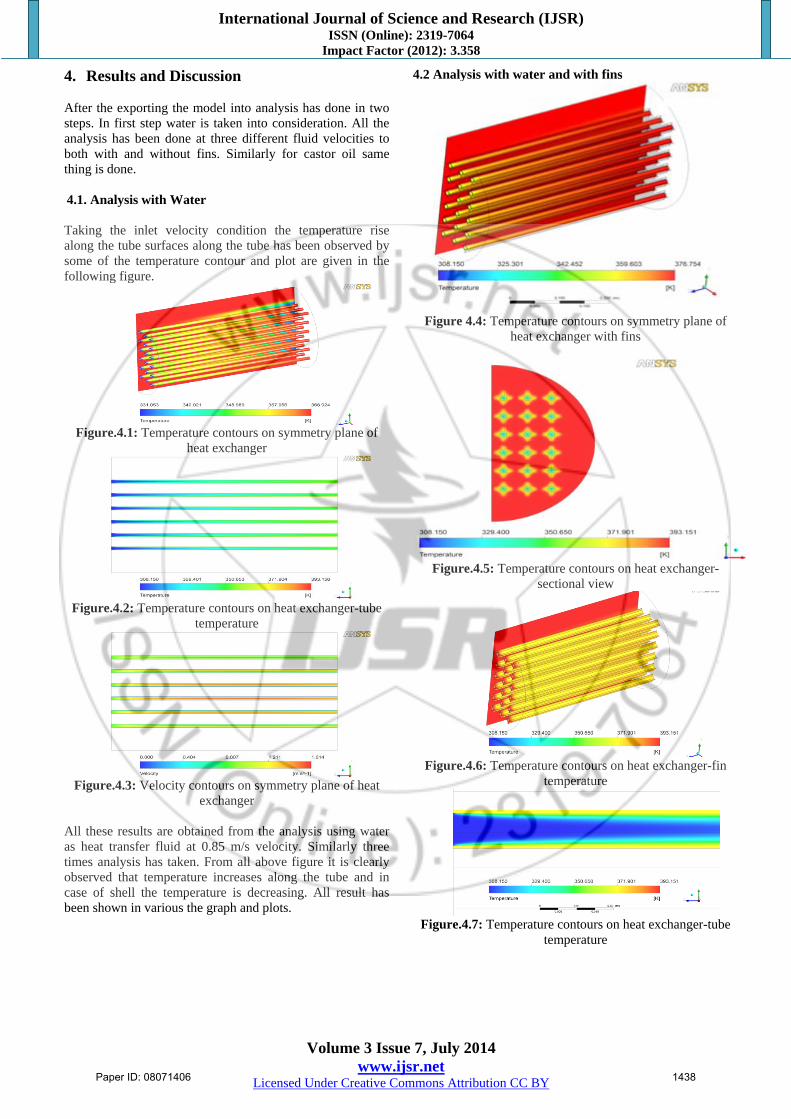
4. Results and Discussion After the exporting the model into analysis has done in two steps. In first step water is taken into consideration. All the analysis has been done at three different fluid velocities to both with and without fins. Similarly for castor oil same thing is done. 4.1. Analysis with Water Taking the inlet velocity condition the temperature rise along the tube surfaces along the tube has been observed by some of the temperature contour and plot are given in the following figure.
Figure.4.1: Temperature contours on symmetry plane of
heat exchanger
Figure.4.2: Temperature contours on heat exchanger-tube
temperature
Figure.4.3: Velocity contours on symmetry plane of heat
exchanger All these results are obtained from the analysis using water as heat transfer fluid at 0.85 m/s velocity. Similarly three times analysis has taken. From all above figure it is clearly observed that temperature increases along the tube and in case of shell the temperature is decreasing. All result has been shown in various the graph and plots.
4.2 Analysis with water and with fins
Figure 4.4: Temperature contours on symmetry plane of
heat exchanger with fins
Figure.4.5: Temperature contours on heat exchanger-
sectional view
Figure.4.6: Temperature contours on heat exchanger-fin
temperature
Figure.4.7: Temperature contours on heat exchanger-tube
temperature
Paper ID: 08071406 1438

International Journal of Science and Research (IJSR) ISSN (Online): 2319-7064
Impact Factor (2012): 3.358
Volume 3 Issue 7, July 2014 www.ijsr.net
Licensed Under Creative Commons Attribution CC BY
Figure 4.8: Velocity contours on tube of heat exchanger
Above figures shows the temperature and velocity contours on tube of heat exchanger with inlet velocity 0.85m/s. and increase in velocity along the tube side. After increasing the velocity both fluids temperature of shell side fluid decreases and tube side fluids increases after exchanging the heat with each other’s. Since shell side fluid become mixed along the path of the flow therefore shell side fluid’s exit temperature become nearly uniform. Pressure drop is observed quite high which indicates the necessity the large pumping power. 4.3 Analysis with castor oil
Figure 4.8:Temperature contours on heat exchanger-tube
temperature
Figure 4.9: Temperature contours on heat exchanger-
sectional view Figure 4.8 aand 4.9 shows temperature contours of heat exchanger.Temperature rise along the tube surfaces has been observed. From the above analysis it is evident that heat transfer is higher in castor oil than water when used, and has better thermal properties than water as heat transfer fluid.
Table 4.1: CFD analysis of shell and tube heat exchanger output without fins.
velocity m/s 0.85 1.25 1.75Water Oil Water Oil Water oil
Shell inlet K 393 393 393 393 393 393Shell outlet K 390.7 390.5 390.2 389.7 389.7 389.3Tube inlet K 308 308 308 308 308 308
Tube outlet K 357.4 364.6 348.3 355.2 341.3 347.5
Table 4.2: CFD analysis of shell and tube heat exchanger output with fins.
velocity m/s 0.85 1.25 1.75Water Oil Water Oil Water oil
Shell inlet K 393 393 393 393 393 393Shell outlet K 390. 389.9 389.7 389.5 389.4 389.Tube inlet K 308 308 308 308 308 308Tube outlet K 364. 372.6 356.1 364.2 347.3 352.5
Table 4.1 and 4.2 shows results of CFD analysis of shell and tube heat exchanger with and without fins by comparing both results it is evident that tube side outlet temperature with fins has higher temperature than that of without fins . And with castor it has better heat transfer than water. This is due to better thermal properties of castor oil than the water. 5. Conclusions An investigation was carried out to study the shell and finned tube heat exchanger computationally using ANSYS fluent 13.0. The geometric modeling of the shell and tube heat exchanger is done by using ANSYS design modeler. And CFD meshing is carried out using ANSYS meshing. The analysis is carried out and pressure drop and temperature rise along the tube surfaces has been investigated. Based on the obtained result it can be concluded as follows; Temperature variation with same velocity for castor oil
and water is greatly noticeable. This is due to better thermal properties of castor oil than the water.
Better effectiveness can be achieved by using castor oil as heat transfer fluid. The effectiveness of the finned tube heat exchanger is quite comparable with other conventional heat exchanger.
Energy extraction rate is also quite significant .that means a sufficient amount of heat can be recovered by using the finned tube heat exchanger.
6. Future Scope of Work
CFD provide alternative to cost effectiveness speedy
solution to heat exchanger design and optimization. Conventional methods used for the design and
development of Heat Exchangers are expensive. CFD results are the integral part of the design process and
it has eliminated the CFD is still a developing art in prediction of erosion/ corrosion due to lack of suitable mathematical models to represent physical process. New flow modeling strategies can be developed for flow simulation in shell and tube heat exchanger
Paper ID: 08071406 1439

International Journal of Science and Research (IJSR) ISSN (Online): 2319-7064
Impact Factor (2012): 3.358
Volume 3 Issue 7, July 2014 www.ijsr.net
Licensed Under Creative Commons Attribution CC BY
Reference
[1] S.N Hossain “CFD simulation of heat transfer in shell and tube heat exchanger” Journal of energy in south Africa – vol17no2 – may 2006
[2] Hilde Vander and Jackodrikes, “ validation of a CFD model of a three dimensional tube in tube heat exchanger “, Third international conference on CFD in the minerals and process industries CSIRO, Melbourne, Australia 10-12 December 2003
[3] V.H.M Orcos,” performance of shell and dimpled tube heat exchanger for waste heat recovery “, Heat recovery systems and CHP volume 8, issue 4, 1988, page 299-308.
[4] Lee dae and Park jaesuk, “ Effect of secondary combination on efficiencies and emission reduction in the diesel engine exhaust heat recovery system “,Journal of Applied energy volume,87,Issue 7, 5th may 2010 pages 1716-1721.
[5] Anizi and A.M-Al-Otaibi “Double performance impingement plate (DPIP) in shell and tube heat exchanger”,7th international conference on heat exchanger fouling and cleaning changes and opportunities July 1-6-2007.
[6] JarkoStevanoic “Design of shell and tube heat exchanger by using CFD technique “, Mechanical engineering, 2001,1091-1105.
[7] Sbari “ Effect different working fluid on shell and tube heat exchanger to recover heat transfer form an automotive diesel engines “, Word removable energy congress 2011 sweden 8-13 may 2001 linkoping, Sweden.
[8] Karuppa raj r and Shrikanthganne, “shell side numerical analysis of a shell and tube heat exchanger considering the effects of baffles Indication angle on fluid flow using CFD” ,Vellor institute of technology Tamil Nadu India
[9] Vikaskumar and D gangacharyulu , “ CFD analysis of cross flow air to air tube type heat exchanger”, Long man scientific & technical, new York 1988
[10] 10. Mohammad reza, tafarinass and Taranazmotevasseli “Non Newtonian fluid analysis using CFD in plate”. Applied thermal engineering, 29, 3299-3308.
Paper ID: 08071406 1440
Related Documents