NATIONAL CONFERENCE ON RECENT TRENDS AND DEVELOPMENTS IN SUSTAINABLE GREEN TECHNOLOGIES-2015 CFD SIMULATION AND ANSYS INVESTIGATION OF C.I.ENGINE COMBUSTION PROCESS BHESHMA YOGENDRA KIRAN.K, RAHUL K & DR.V.MUTHU DEPARTMENT OF AUTOMOBILE ENGINEERING, RAJALAKSHMI ENGINEERING COLLEGE, CHENNAI. EMAIL id: [email protected] , [email protected] ABSTRACT In past, the diesel combustion process has been modeled and analyzed theoretically by several experts all around the world. The advancement of computational tools saves time and production cost. Better performance and reduced emission engines are a result of computational fluid dynamics analysis software such as FLUENT and STAR-CD ADAPCO. A single cylinder KIRLOSKAR TV-1 diesel engine was taken for simulation. The clearance height for bowl type piston combustion chamber was calculated and modeled in GAMBIT and CATIA. The results obtained from analysis were compared with experimental investigation in terms of pressure vs crank angle. For the same engine, clearance height for flat type piston was calculated with same compression ratio 17.5:1 and modeled in gambit. The errors are calculated and studied and results are compared. Keywords: CFD, FLUENT, KIRLOSKAR TV-1, COMPRESSION RATIO, CETANE NUMBER I. INTRODUCTION: The IC engine is the engine where combustion of a fuel occurs with oxidizer (air) in a combustion chamber. In an internal combustion engine, the expansion of high temperature and high pressure gases produced by combustion apply direct force to some component of the engine. This force moves the component over a distance, transforming chemical energy into useful mechanical energy. Combustion is the physical phenomenon where mathematical solutions can also be impossible to arrive at accuracy, combustion takes place by milliseconds so no one has capable to see fire is produced or not. Especially on CI engines, combustion takes place by compression of fuel and air in localized unlike Si engines it don’t have any spark plug to fire, so the study of CI engine combustion lets you know how on compressing it gets combusted or reaches self-ignition temperature. II. DIESEL COMBUSTION PROCESS: Diesel engines rely solely on heat and pressure created by engine in its compression process for ignition. The compression level that occurs is usually twice or more than a gasoline engine. Diesel engines will take in air only and shortly before peak compression, a small quantity of diesel fuel is sprayed into the cylinder via fuel injector allows to instant ignite that too heterogeneous mixture of combustion in localized areas. They have reputation for having excellent reputation for their low fuel consumption, reliability and durability characteristics, known for low HC and CO emission fuel. But known for their soot formation and particulate matter as well as NOX emissions. The basic premise of diesel combustion in its unique way of releasing the chemical energy stored in the fuel. They are characterized by lean mixture of air and fuel mass ratio with 20:1 to 100:1 in wide optimum range. Parameters affecting combustion: Inducted air charge, injected fuel atomization, compression ratio, injection pressure and timing, hole size, nozzle hole geometry spray geometry valve configuration and top piston ring position. It is therefore important to realize that combustion system of diesel engine is not limited to combustion bowl,

Welcome message from author
This document is posted to help you gain knowledge. Please leave a comment to let me know what you think about it! Share it to your friends and learn new things together.
Transcript
NATIONAL CONFERENCE ON RECENT TRENDS AND DEVELOPMENTS IN SUSTAINABLE GREENTECHNOLOGIES-2015
CFD SIMULATION AND ANSYS INVESTIGATION OF C.I.ENGINE COMBUSTION PROCESS
BHESHMA YOGENDRA KIRAN.K, RAHUL K & DR.V.MUTHUDEPARTMENT OF AUTOMOBILE ENGINEERING, RAJALAKSHMI ENGINEERING COLLEGE, CHENNAI.EMAIL id: [email protected] , [email protected] ABSTRACTIn past, the diesel combustion process has been modeled and analyzed theoreticallyby several experts all around the world. The advancement of computational toolssaves time and production cost. Better performance and reduced emission enginesare a result of computational fluid dynamics analysis software such as FLUENT andSTAR-CD ADAPCO. A single cylinder KIRLOSKAR TV-1 diesel engine was taken forsimulation. The clearance height for bowl type piston combustion chamber wascalculated and modeled in GAMBIT and CATIA. The results obtained from analysiswere compared with experimental investigation in terms of pressure vs crank angle.For the same engine, clearance height for flat type piston was calculated withsame compression ratio 17.5:1 and modeled in gambit. The errors are calculated andstudied and results are compared.Keywords: CFD, FLUENT, KIRLOSKAR TV-1, COMPRESSION RATIO, CETANE NUMBERI. INTRODUCTION:The IC engine is the engine where combustion of a fuel occurs with oxidizer (air)in a combustion chamber. In an internal combustion engine, the expansion of hightemperature and high pressure gases produced by combustion apply direct force tosome component of the engine. This force moves the component over a distance,transforming chemical energy into useful mechanical energy. Combustion is thephysical phenomenon where mathematical solutions can also be impossible to arriveat accuracy, combustion takes place by milliseconds so no one has capable to seefire is produced or not. Especially on CI engines, combustion takes place bycompression of fuel and air in localized unlike Si engines it don’t have any sparkplug to fire, so the study of CI engine combustion lets you know how oncompressing it gets combusted or reaches self-ignition temperature.II. DIESEL COMBUSTION PROCESS:Diesel engines rely solely on heat and pressure created by engine in itscompression process for ignition. The compression level that occurs is usuallytwice or more than a gasoline engine. Diesel engines will take in air only andshortly before peak compression, a small quantity of diesel fuel is sprayed intothe cylinder via fuel injector allows to instant ignite that too heterogeneousmixture of combustion in localized areas. They have reputation for havingexcellent reputation for their low fuel consumption, reliability and durabilitycharacteristics, known for low HC and CO emission fuel. But known for their sootformation and particulate matter as well as NOX emissions. The basic premise ofdiesel combustion in its unique way of releasing the chemical energy stored in thefuel. They are characterized by lean mixture of air and fuel mass ratio with 20:1to 100:1 in wide optimum range.
Parameters affecting combustion:Inducted air charge, injected fuel atomization, compression ratio, injectionpressure and timing, hole size, nozzle hole geometry spray geometry valveconfiguration and top piston ring position. It is therefore important to realizethat combustion system of diesel engine is not limited to combustion bowl,
NATIONAL CONFERENCE ON RECENT TRENDS AND DEVELOPMENTS IN SUSTAINABLE GREENTECHNOLOGIES-2015
injector sprays and their immediate surroundings. Rather it includes any partcomponent system that may effect final outcomes of process.III. CFD SIMULATION IN CI ENGINE: Applying the laws of fluid dynamics and studying about the combustion process andvariation approach in the reactions are equated to mathematical equations withcomputer algorithms to produce software for visualizing date to render graphicalsolutions. The software FLUENT is used on the basis of CFD.Steps involved in analyzing:
Creating geometry Model is setup for meshing Creating named sections such as inlet and outlet. D Defining boundary conditions
Analyzing and yielding result. We are analyzing the static failure and dynamicfailure with ANSYS. We are comparing the bowl type and flat type pistons and theircombustion reactions.
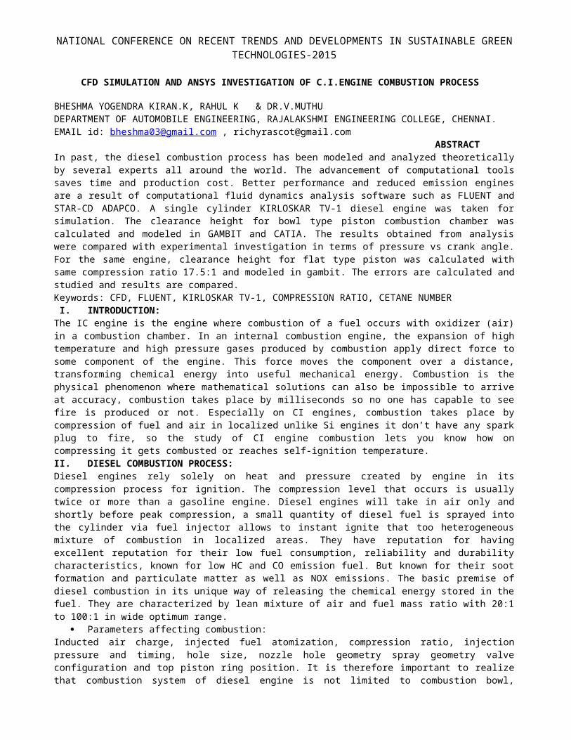
MESHING: Coarse medium and fine mesh are classification.
Mesh type: Tetrahedral fine mesh.
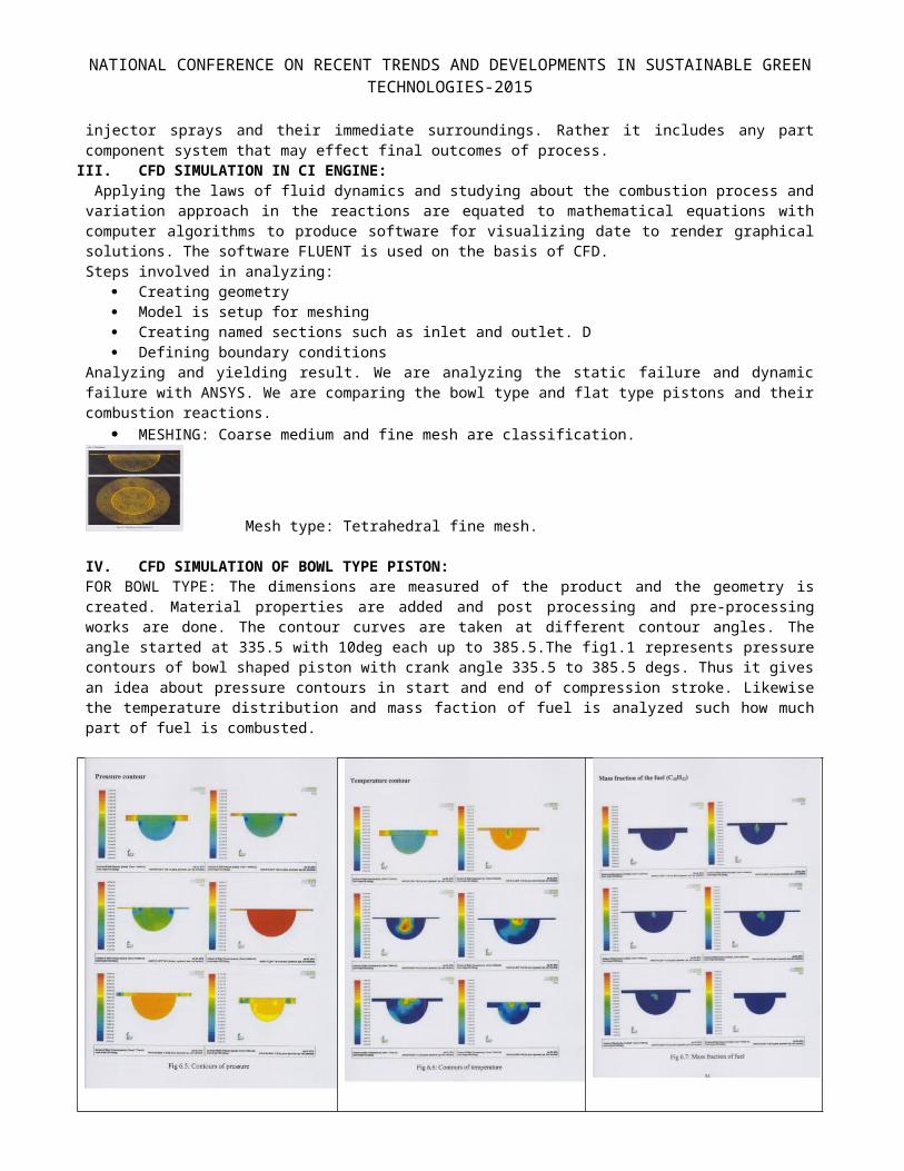
IV. CFD SIMULATION OF BOWL TYPE PISTON:FOR BOWL TYPE: The dimensions are measured of the product and the geometry iscreated. Material properties are added and post processing and pre-processingworks are done. The contour curves are taken at different contour angles. Theangle started at 335.5 with 10deg each up to 385.5.The fig1.1 represents pressurecontours of bowl shaped piston with crank angle 335.5 to 385.5 degs. Thus it givesan idea about pressure contours in start and end of compression stroke. Likewisethe temperature distribution and mass faction of fuel is analyzed such how muchpart of fuel is combusted.
NATIONAL CONFERENCE ON RECENT TRENDS AND DEVELOPMENTS IN SUSTAINABLE GREENTECHNOLOGIES-2015
Figure 1.1:pressure contour
Figure 1.2:Temperaturecontour
Figure 1.3:Mass fractionof fuel
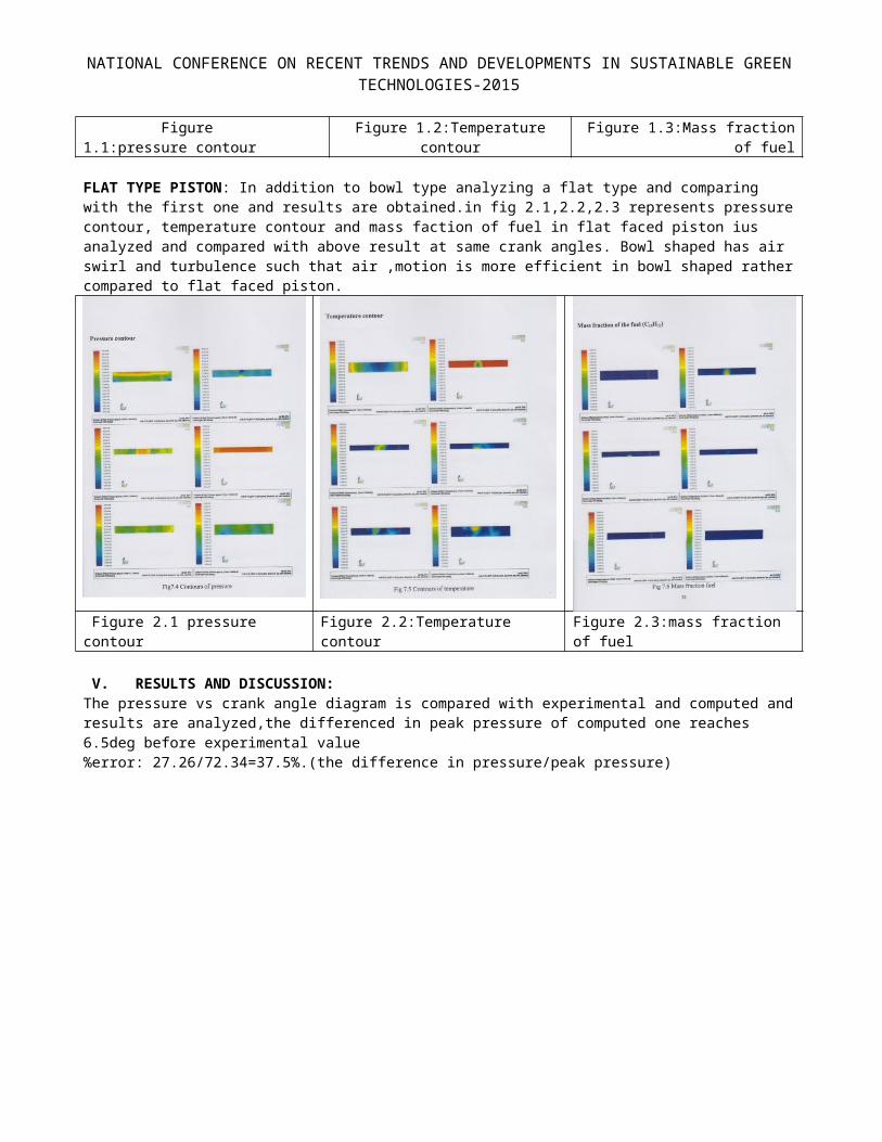
FLAT TYPE PISTON: In addition to bowl type analyzing a flat type and comparing with the first one and results are obtained.in fig 2.1,2.2,2.3 represents pressurecontour, temperature contour and mass faction of fuel in flat faced piston ius analyzed and compared with above result at same crank angles. Bowl shaped has air swirl and turbulence such that air ,motion is more efficient in bowl shaped rathercompared to flat faced piston.
Figure 2.1 pressure contour
Figure 2.2:Temperature contour
Figure 2.3:mass fraction of fuel
V. RESULTS AND DISCUSSION:The pressure vs crank angle diagram is compared with experimental and computed andresults are analyzed,the differenced in peak pressure of computed one reaches 6.5deg before experimental value%error: 27.26/72.34=37.5%.(the difference in pressure/peak pressure)
NATIONAL CONFERENCE ON RECENT TRENDS AND DEVELOPMENTS IN SUSTAINABLE GREENTECHNOLOGIES-2015
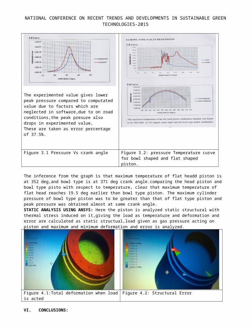
The experimented value gives lower peak pressure compared to computated value due to factors which are neglected in software,due to on road conditions,the peak presure also drops in experimented value,These are taken as error percentage of 37.5%.
Figure 3.1 Pressure Vs crank angle Figure 3.2: pressure Temperature curvefor bowl shaped and flat shaped piston.
The inference from the graph is that maximum temperature of flat headd piston is at 352 deg,and bowl type is at 371 deg crank angle.comparing the head piston and bowl type pisto with respect to temperature, clear that maximum temperature of flat head reaches 19.5 deg earlier than bowl type piston. The maximum cylinder pressure of bowl type piston was to be greater than that of flat type piston and peak pressure was obtained almost at same crank angle.STATIC ANALYSIS USING ANSYS: Here the piston is analyzed static structural with thermal stress induced on it,giving the load as temperature and deformation and error are calculated as static structual,load given as gas pressure acting on piston and maximum and minimum deformation and error is analyzed.
Figure 4.1:Total deformation when loadis acted
Figure 4.2: Structural Error
VI. CONCLUSIONS:

NATIONAL CONFERENCE ON RECENT TRENDS AND DEVELOPMENTS IN SUSTAINABLE GREENTECHNOLOGIES-2015
The various results generated from combustion chamber simulation of CI engine helps to understand significance of piston geometry. The accuracy of results is improved as elements are increase or meshing size increases.the development of bowl type piston induces swirl motion of air.the CFD model and ANSYS model can de a reliable tool of internal combustion engines.VII. ACKNOWLEDGEMENT: I sincerely thank my faculty advisor for bringing my idea alive and gave an intense support to make this paper.
VIII. REFERENCES:1.K.Purushothamam,G.nagarajan,2009.,”Performance,Emission and combustion characteristics of CI engineoperating on neat orange oil.,Renewable energy 34(2009)242-2452.Antony Raj GnanaSgayaRaj.,jawali Maharudppa mallikarjuna.,venktichalam Gnesan 2013”Energy Efficient piston Configuration for effective air motion-A CFD study.Applied Energy 102(2013)347-3543.”Internal Combustion Engines” by V Ganesan.4.”Internal Combustion Engines-fundamental”by john B.Heywood.

NATIONAL CONFERENCE ON RECENT TRENDS AND DEVELOPMENTS IN SUSTAINABLE GREENTECHNOLOGIES-2015
Related Documents