20. Internationales Holzbau-Forum IHF 2014 CESM Soccer Center in Montreal | Etienne Mondou 1 CESM Soccer Center in Montreal Etienne Mondou Nordic Wood Structures Montreal, Canada

Welcome message from author
This document is posted to help you gain knowledge. Please leave a comment to let me know what you think about it! Share it to your friends and learn new things together.
Transcript
20. Internationales Holzbau-Forum IHF 2014 CESM Soccer Center in Montreal | Etienne Mondou
1
CESM Soccer Center in Montreal
Etienne Mondou Nordic Wood Structures
Montreal, Canada
20. Internationales Holzbau-Forum IHF 2014 CESM Soccer Center in Montreal | Etienne Mondou
2
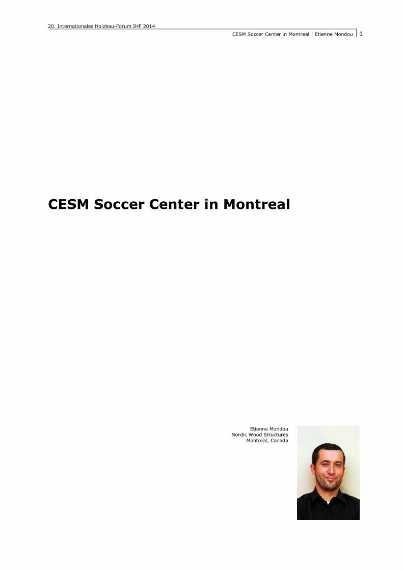
CESM Soccer Center in Montreal[5] 1. Introduction The CESM soccer center is a sports complex located in the Villeray, Saint-Michel, Parc-Extension borough in the heart of Montreal, Quebec. It houses a standard size soccer pitch with seating for 750 spectators, training facilities, public spaces and offices. The building is 110 m long, 78 m wide, 18 m high. The flat roof, spanning 69 m over the playing field, is a wood structure supported by steel columns. The other sectors of the building are constructed of traditional steel and concrete.
This unique building concept was developed by the architectural firms Saucier+Perrotte and Hughes Condon Marler, winners of an architectural design contest, organized by the city of Montreal. The roof of the building recalls the rocky aspect and the mineral stratifi-cation of the former quarry where this project has been built. The wood structure, was tendered out as a design-build project, to be integrated into the structural and architectural concept. This was made to give the time needed to do the conception of the main beams and make tests to validate differents aspects of the de-sign. Nordic, a glulam and CLT manufacturer, supported by SNC-Lavalin (engineering) and FGP construction (erection), was selected for the contract.
Figure 1: Architectural render of the final building [1]
2. Wooden roof The main part of the roof consists of 13 principal beams spanning 69 m. Each beam is supported by steel columns spaced at an interval of 8 m. The beams are at an angle such that the supports at either end of the beams are on different column grid lines. Decorati-ve beams attached to the bottom flange of the primary beams, placed in a diagonal pat-tern, provide the checkered visual effect desired in the architectural concept.
20. Internationales Holzbau-Forum IHF 2014 CESM Soccer Center in Montreal | Etienne Mondou
3
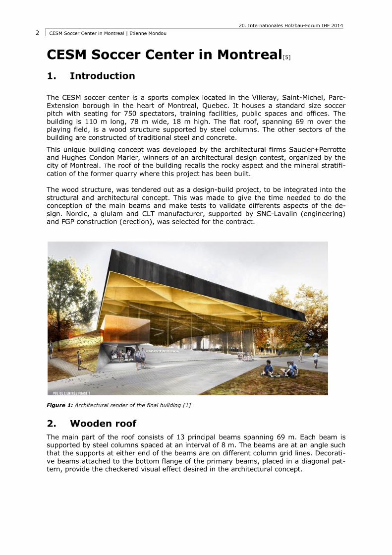
Figure 2: Isometric view of the structure
The East side of the roof protrudes out from the facade by 10 meters, while on the West side of the building, two shoulders span more than 40 meters from the roof diagonally down to concrete abutments, located at ground level. The roof decking consists of 3 ply, 105 mm cross-laminated timber (CLT) panels that are supported by glulam purlins. These secondary roof members have a 5.3 meters spacing and span 8 meters between the principal beams. The roof is designed to support the local snow loads of 2.8 kPa.
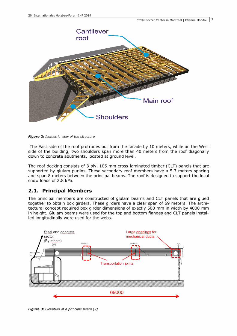
2.1. Principal Members The principal members are constructed of glulam beams and CLT panels that are glued together to obtain box girders. These girders have a clear span of 69 meters. The archi-tectural concept required box girder dimensions of exactly 500 mm in width by 4000 mm in height. Glulam beams were used for the top and bottom flanges and CLT panels instal-led longitudinally were used for the webs.
Figure 3: Elevation of a principle beam [2]

20. Internationales Holzbau-Forum IHF 2014 CESM Soccer Center in Montreal | Etienne Mondou
4
The use of box beams was preferred to solid glue-laminated beams in order to reduce overall weight. This facilitated the design of the connections, transportation and erection of the girders. Another advantage was a reduction in overall shrinkage. One of the main benefits of CLT is its dimensional stability, provided by its cross-laminated fabrication. The longitudinal fibers restrain the perpendicular fibers from dimensional changes. The use of CLT as the web of the girders, allows for a reduction in half of the anticipated shrinkage on the height of the beam and only the flanges need to be considered.
As illustrated in figure 4 below, the beam top and bottom flanges have a height of 1200 mm and 1400 mm respectively. The CLT webs consist of 3 ply, 105 mm panels for the central section of the beam. Due to the increased shear stresses in the beam sections near the supports, 5-ply, 158 mm CLT panels were used as the webs. Cut-outs were ma-de on the glulam flanges (300 mm and 200 mm in height respectively for the exterior and central sections) to create a ‘‘lip‘‘, in order to glue the CLT webs to the glulam flan-ges.
Figure 4: Cross-section through principal beam [2]
The beam-column bearing support detail illustrated in figure 5 below, was developed for structural reasons to lower the maximum shear in the CLT webs. It was also detailed to accommodate large ventilation ducts within the web of the beams on the perimeter of the building.
Figure 5: Beam-column bearing support [2]
20. Internationales Holzbau-Forum IHF 2014 CESM Soccer Center in Montreal | Etienne Mondou
5
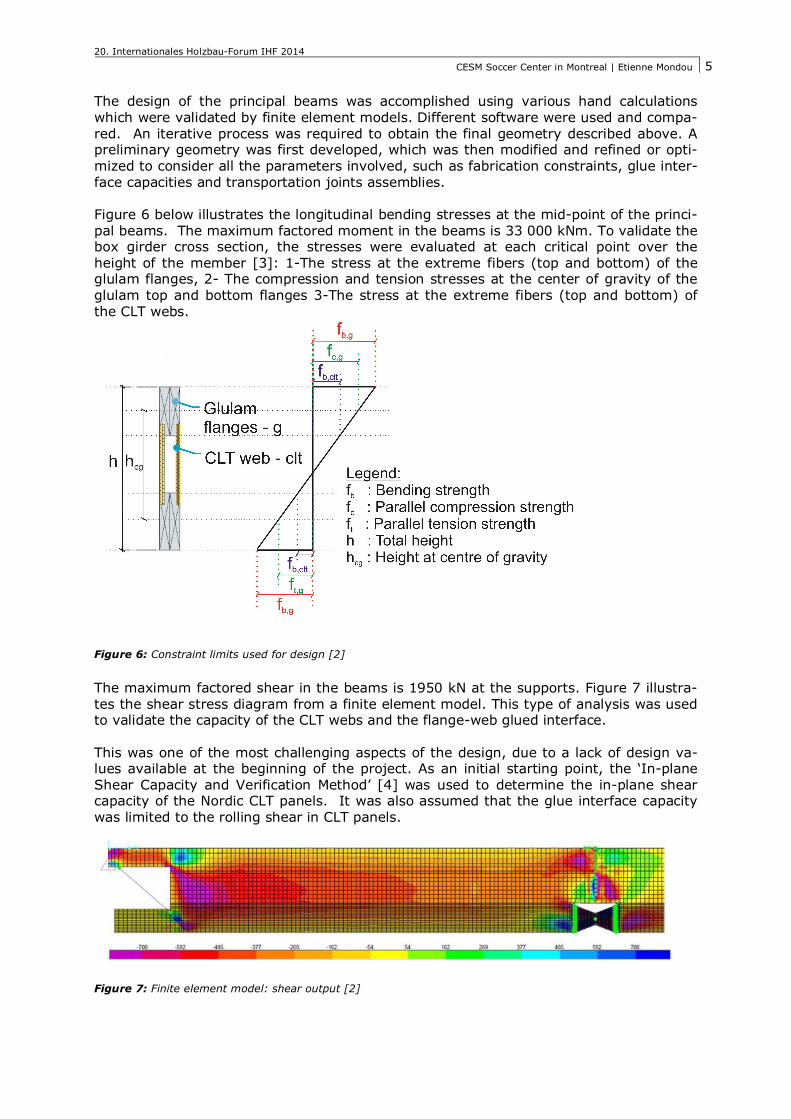
The design of the principal beams was accomplished using various hand calculations which were validated by finite element models. Different software were used and compa-red. An iterative process was required to obtain the final geometry described above. A preliminary geometry was first developed, which was then modified and refined or opti-mized to consider all the parameters involved, such as fabrication constraints, glue inter-face capacities and transportation joints assemblies. Figure 6 below illustrates the longitudinal bending stresses at the mid-point of the princi-pal beams. The maximum factored moment in the beams is 33 000 kNm. To validate the box girder cross section, the stresses were evaluated at each critical point over the height of the member [3]: 1-The stress at the extreme fibers (top and bottom) of the glulam flanges, 2- The compression and tension stresses at the center of gravity of the glulam top and bottom flanges 3-The stress at the extreme fibers (top and bottom) of the CLT webs.
Figure 6: Constraint limits used for design [2]
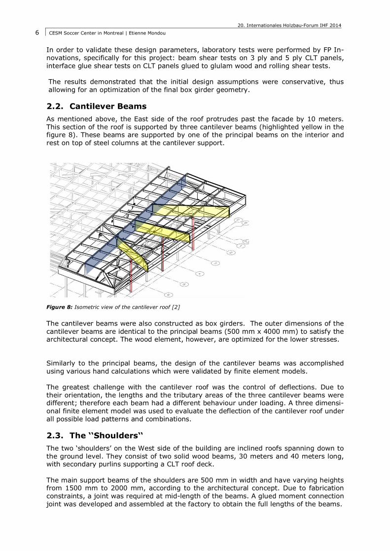
The maximum factored shear in the beams is 1950 kN at the supports. Figure 7 illustra-tes the shear stress diagram from a finite element model. This type of analysis was used to validate the capacity of the CLT webs and the flange-web glued interface. This was one of the most challenging aspects of the design, due to a lack of design va-lues available at the beginning of the project. As an initial starting point, the ‘In-plane Shear Capacity and Verification Method’ [4] was used to determine the in-plane shear capacity of the Nordic CLT panels. It was also assumed that the glue interface capacity was limited to the rolling shear in CLT panels.
Figure 7: Finite element model: shear output [2]
20. Internationales Holzbau-Forum IHF 2014 CESM Soccer Center in Montreal | Etienne Mondou
6
In order to validate these design parameters, laboratory tests were performed by FP In-novations, specifically for this project: beam shear tests on 3 ply and 5 ply CLT panels, interface glue shear tests on CLT panels glued to glulam wood and rolling shear tests. The results demonstrated that the initial design assumptions were conservative, thus allowing for an optimization of the final box girder geometry.
2.2. Cantilever Beams As mentioned above, the East side of the roof protrudes past the facade by 10 meters. This section of the roof is supported by three cantilever beams (highlighted yellow in the figure 8). These beams are supported by one of the principal beams on the interior and rest on top of steel columns at the cantilever support.
Figure 8: Isometric view of the cantilever roof [2]
The cantilever beams were also constructed as box girders. The outer dimensions of the cantilever beams are identical to the principal beams (500 mm x 4000 mm) to satisfy the architectural concept. The wood element, however, are optimized for the lower stresses. Similarly to the principal beams, the design of the cantilever beams was accomplished using various hand calculations which were validated by finite element models. The greatest challenge with the cantilever roof was the control of deflections. Due to their orientation, the lengths and the tributary areas of the three cantilever beams were different; therefore each beam had a different behaviour under loading. A three dimensi-onal finite element model was used to evaluate the deflection of the cantilever roof under all possible load patterns and combinations.
2.3. The ‘‘Shoulders‘‘ The two ‘shoulders’ on the West side of the building are inclined roofs spanning down to the ground level. They consist of two solid wood beams, 30 meters and 40 meters long, with secondary purlins supporting a CLT roof deck. The main support beams of the shoulders are 500 mm in width and have varying heights from 1500 mm to 2000 mm, according to the architectural concept. Due to fabrication constraints, a joint was required at mid-length of the beams. A glued moment connection joint was developed and assembled at the factory to obtain the full lengths of the beams.
20. Internationales Holzbau-Forum IHF 2014 CESM Soccer Center in Montreal | Etienne Mondou
7
Figure 9: Isometric view of a shoulder
3. Connections
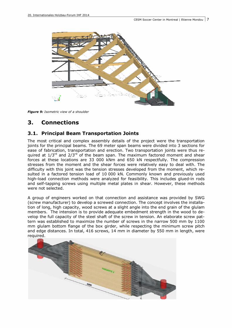
3.1. Principal Beam Transportation Joints The most critical and complex assembly details of the project were the transportation joints for the principal beams. The 69 meter span beams were divided into 3 sections for ease of fabrication, transportation and erection. Two transportation joints were thus re-quired at 1/3rd and 2/3rd of the beam span. The maximum factored moment and shear forces at these locations are 33 000 kNm and 650 kN respectfully. The compression stresses from the moment and the shear forces were relatively easy to deal with. The difficulty with this joint was the tension stresses developed from the moment, which re-sulted in a factored tension load of 10 000 kN. Commonly known and previously used high-load connection methods were analyzed for feasibility. This includes glued-in rods and self-tapping screws using multiple metal plates in shear. However, these methods were not selected. A group of engineers worked on that connection and assistance was provided by SWG (screw manufacturer) to develop a screwed connection. The concept involves the installa-tion of long, high capacity, wood screws at a slight angle into the end grain of the glulam members. The intension is to provide adequate embedment strength in the wood to de-velop the full capacity of the steel shaft of the screw in tension. An elaborate screw pat-tern was established to maximize the number of screws in the narrow 500 mm by 1100 mm glulam bottom flange of the box girder, while respecting the minimum screw pitch and edge distances. In total, 416 screws, 14 mm in diameter by 550 mm in length, were required.
20. Internationales Holzbau-Forum IHF 2014 CESM Soccer Center in Montreal | Etienne Mondou
8
Figure 10: Test setup for the tension connection
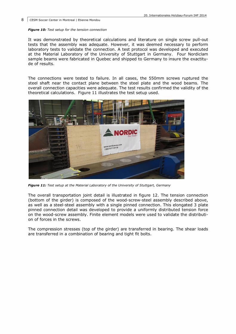
It was demonstrated by theoretical calculations and literature on single screw pull-out tests that the assembly was adequate. However, it was deemed necessary to perform laboratory tests to validate the connection. A test protocol was developed and executed at the Material Laboratory of the University of Stuttgart in Germany. Four Nordiclam sample beams were fabricated in Quebec and shipped to Germany to insure the exactitu-de of results. The connections were tested to failure. In all cases, the 550mm screws ruptured the steel shaft near the contact plane between the steel plate and the wood beams. The overall connection capacities were adequate. The test results confirmed the validity of the theoretical calculations. Figure 11 illustrates the test setup used.
Figure 11: Test setup at the Material Laboratory of the University of Stuttgart, Germany
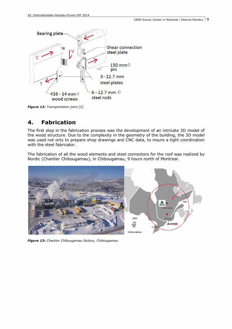
The overall transportation joint detail is illustrated in figure 12. The tension connection (bottom of the girder) is composed of the wood-screw-steel assembly described above, as well as a steel-steel assembly with a single pinned connection. This elongated 3 plate pinned connection detail was developed to provide a uniformly distributed tension force on the wood-screw assembly. Finite element models were used to validate the distributi-on of forces in the screws. The compression stresses (top of the girder) are transferred in bearing. The shear loads are transferred in a combination of bearing and tight fit bolts.
20. Internationales Holzbau-Forum IHF 2014 CESM Soccer Center in Montreal | Etienne Mondou
9
Figure 12: Transportation joint [2]
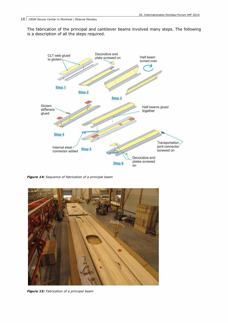
4. Fabrication The first step in the fabrication process was the development of an intricate 3D model of the wood structure. Due to the complexity in the geometry of the building, the 3D model was used not only to prepare shop drawings and CNC data, to insure a tight coordination with the steel fabricator. The fabrication of all the wood elements and steel connectors for the roof was realized by Nordic (Chantier Chibougamau), in Chibougamau, 9 hours north of Montreal.
Figure 13: Chantier Chibougamau factory, Chibougamau
20. Internationales Holzbau-Forum IHF 2014 CESM Soccer Center in Montreal | Etienne Mondou
10
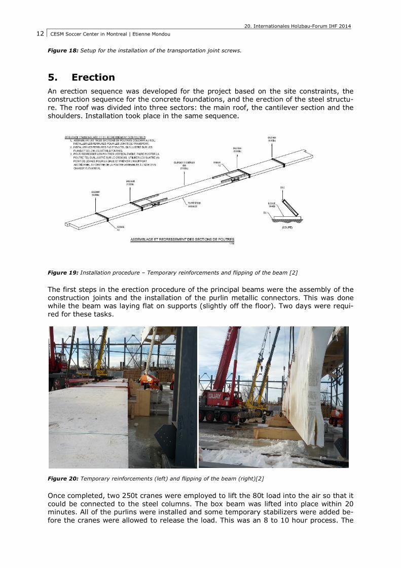
The fabrication of the principal and cantilever beams involved many steps. The following is a description of all the steps required.
Figure 14: Sequence of fabrication of a principal beam
Figure 15: Fabrication of a principal beam

20. Internationales Holzbau-Forum IHF 2014 CESM Soccer Center in Montreal | Etienne Mondou
11
Figure 16: Fabrication of a principal beam, flipping of half section
Figure 17: Fabrication of a principal beam, gluing half-parts together
All the wood screws for the transportation joints were installed in the shop. Due to the tight configuration and length of the screws, a custom steel support was made to ensure the precision of installation. A quality insurance protocol was implemented to control the quality of all the work done.
20. Internationales Holzbau-Forum IHF 2014 CESM Soccer Center in Montreal | Etienne Mondou
12
Figure 18: Setup for the installation of the transportation joint screws.
5. Erection An erection sequence was developed for the project based on the site constraints, the construction sequence for the concrete foundations, and the erection of the steel structu-re. The roof was divided into three sectors: the main roof, the cantilever section and the shoulders. Installation took place in the same sequence.
Figure 19: Installation procedure – Temporary reinforcements and flipping of the beam [2]
The first steps in the erection procedure of the principal beams were the assembly of the construction joints and the installation of the purlin metallic connectors. This was done while the beam was laying flat on supports (slightly off the floor). Two days were requi-red for these tasks.
Figure 20: Temporary reinforcements (left) and flipping of the beam (right)[2]
Once completed, two 250t cranes were employed to lift the 80t load into the air so that it could be connected to the steel columns. The box beam was lifted into place within 20 minutes. All of the purlins were installed and some temporary stabilizers were added be-fore the cranes were allowed to release the load. This was an 8 to 10 hour process. The

20. Internationales Holzbau-Forum IHF 2014 CESM Soccer Center in Montreal | Etienne Mondou
13
beams were installed at a rate of one per week. Due to the length of the principal beams and the lifting constraints, the erection of the steel structure was completed progressive-ly as the wood roof was erected. Tight coordination between the sub trades was required for this process.
Figure 21: Installation of the second principle beam
Precautions were taken to ensure that the wood structure stayed clean during the con-struction period. The plastic wrap used for shipping was left on the principal beams until completion of the roofing in order to protect the wood. The waterproofing and the tempo-rary drainage system was completed immediately as the erection of the roof progressed. This step significantly reduce the touch-ups (sanding/cleaning) usually required once a structure is erected.
Figure 22: Installation of the cantilever beams
20. Internationales Holzbau-Forum IHF 2014 CESM Soccer Center in Montreal | Etienne Mondou
14
Figure 23: Installation of the ’’Shoulders’’
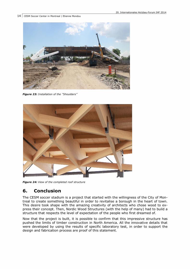
Figure 24: View of the completed roof structure
6. Conclusion The CESM soccer stadium is a project that started with the willingness of the City of Mon-treal to create something beautiful in order to revitalise a borough in the heart of town. This desire took shape with the amazing creativity of architects who chose wood to ex-press their concept. Then, Nordic Wood Structures (with the help of many) had to build a structure that respects the level of expectation of the people who first dreamed of.
Now that the project is built, it is possible to confirm that this impressive structure has pushed the limits of timber construction in North America. All the innovative details that were developed by using the results of specific laboratory test, in order to support the design and fabrication process are proof of this statement.
20. Internationales Holzbau-Forum IHF 2014 CESM Soccer Center in Montreal | Etienne Mondou
15
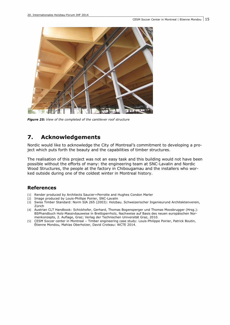
Figure 25: View of the completed of the cantilever roof structure
7. Acknowledgements Nordic would like to acknowledge the City of Montreal’s commitment to developing a pro-ject which puts forth the beauty and the capabilities of timber structures. The realisation of this project was not an easy task and this building would not have been possible without the efforts of many: the engineering team at SNC-Lavalin and Nordic Wood Structures, the people at the factory in Chibougamau and the installers who wor-ked outside during one of the coldest winter in Montreal history.
References [1] Render produced by Architects Saucier+Perrotte and Hughes Condon Marler [2] Image produced by Louis-Phillipe Poirier, SNC-Lavalin [3] Swiss Timber Standard: Norm SIA 265 (2003): Holzbau. Schweizerischer Ingenieurund Architektenverein,
Zürich [4] Austrian CLT Handbook: Schickhofer, Gerhard, Thomas Bogensperger und Thomas Moosbrugger (Hrsg.):
BSPhandbuch Holz-Massivbauweise in Brettsperrholz, Nachweise auf Basis des neuen europäischen Nor-menkonzepts, 2. Auflage, Graz; Verlag der Technischen Universität Graz, 2010.
[5] CESM Soccer center in Montreal – Timber engineering case study: Louis-Philippe Poirier, Patrick Boutin, Étienne Mondou, Mahias Oberholzer, David Croteau: WCTE 2014.
Related Documents