SOLUTIONS CATALOG Certification, troubleshooting, and installation tools for professionals who install and maintain critical network cable infrastructure Certification, troubleshooting, and installation tools for professionals who install and maintain critical network cable infrastructure

Welcome message from author
This document is posted to help you gain knowledge. Please leave a comment to let me know what you think about it! Share it to your friends and learn new things together.
Transcript
SOLUTIONS CATALOG
Certification, troubleshooting, and installation tools for professionals who install and maintain
critical network cable infrastructure
Certification, troubleshooting, and installation tools for professionals who install and maintain
critical network cable infrastructure
c
r
m1-800-283-5853 (US and Canada) • www.flukenetworks.com 3
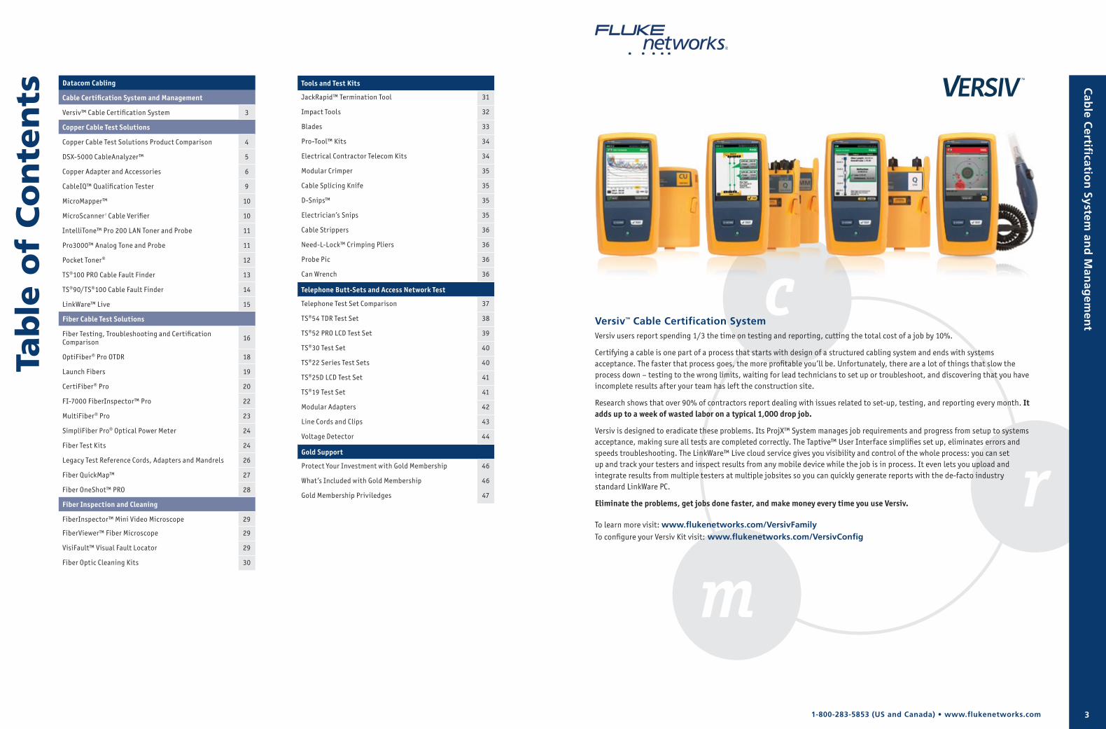
Datacom Cabling
Cable Certification System and Management
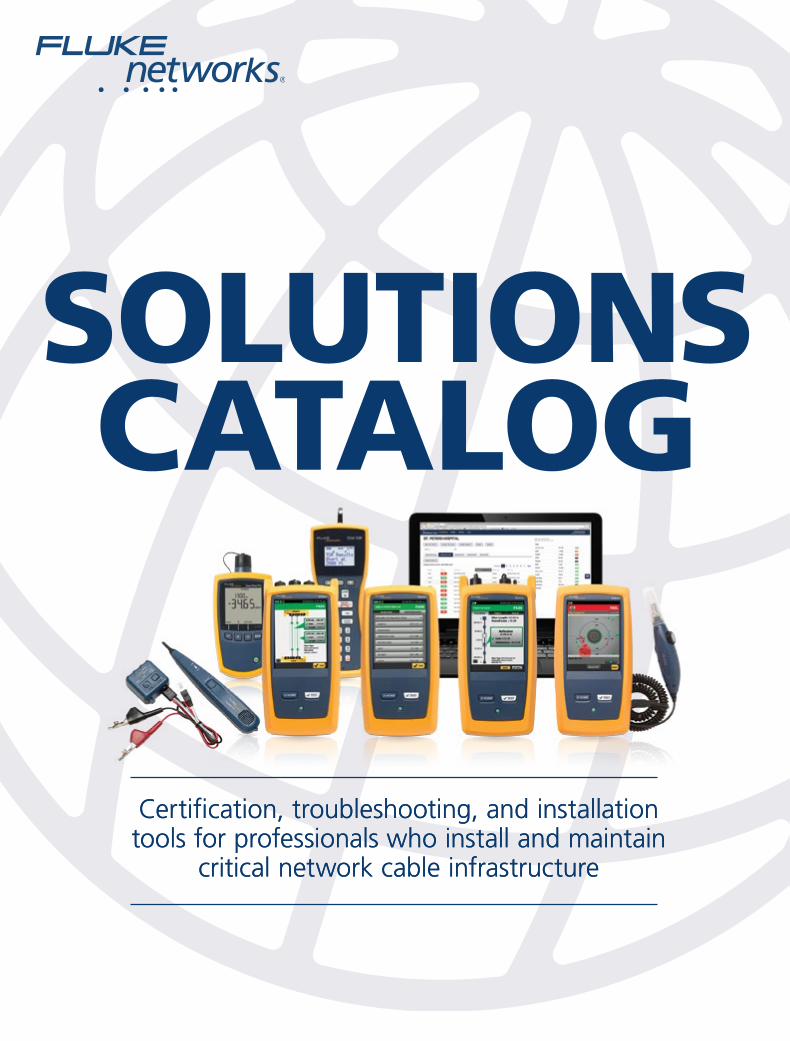
Versiv™ Cable Certification System 3
Copper Cable Test Solutions
Copper Cable Test Solutions Product Comparison 4
DSX-5000 CableAnalyzer™ 5
Copper Adapter and Accessories 6
CableIQ™ Qualification Tester 9
MicroMapper™ 10
MicroScanner 2 Cable Verifier 10
IntelliTone™ Pro 200 LAN Toner and Probe 11
Pro3000™ Analog Tone and Probe 11
Pocket Toner® 12
TS®100 PRO Cable Fault Finder 13
TS®90/TS®100 Cable Fault Finder 14
LinkWare™ Live 15
Fiber Cable Test Solutions
Fiber Testing, Troubleshooting and Certification Comparison 16
OptiFiber® Pro OTDR 18
Launch Fibers 19
CertiFiber® Pro 20
FI-7000 FiberInspector™ Pro 22
MultiFiber® Pro 23
SimpliFiber Pro® Optical Power Meter 24
Fiber Test Kits 24
Legacy Test Reference Cords, Adapters and Mandrels 26
Fiber QuickMap™ 27
Fiber OneShot™ PRO 28
Fiber Inspection and Cleaning
FiberInspector™ Mini Video Microscope 29
FiberViewer™ Fiber Microscope 29
VisiFault™ Visual Fault Locator 29
Fiber Optic Cleaning Kits 30
Tools and Test Kits
JackRapid™ Termination Tool 31
Impact Tools 32
Blades 33
Pro-Tool™ Kits 34
Electrical Contractor Telecom Kits 34
Modular Crimper 35
Cable Splicing Knife 35
D-Snips™ 35
Electrician’s Snips 35
Cable Strippers 36
Need-L-Lock™ Crimping Pliers 36
Probe Pic 36
Can Wrench 36
Telephone Butt-Sets and Access Network Test
Telephone Test Set Comparison 37
TS®54 TDR Test Set 38
TS®52 PRO LCD Test Set 39
TS®30 Test Set 40
TS®22 Series Test Sets 40
TS®25D LCD Test Set 41
TS®19 Test Set 41
Modular Adapters 42
Line Cords and Clips 43
Voltage Detector 44
Gold Support
Protect Your Investment with Gold Membership 46
What’s Included with Gold Membership 46
Gold Membership Priviledges 47
Ta
ble
of
Co
nte
nts
Versiv™ Cable Certification SystemVersiv users report spending 1/3 the time on testing and reporting, cutting the total cost of a job by 10%.
Certifying a cable is one part of a process that starts with design of a structured cabling system and ends with systems acceptance. The faster that process goes, the more profitable you’ll be. Unfortunately, there are a lot of things that slow the process down – testing to the wrong limits, waiting for lead technicians to set up or troubleshoot, and discovering that you have incomplete results after your team has left the construction site.
Research shows that over 90% of contractors report dealing with issues related to set-up, testing, and reporting every month. It adds up to a week of wasted labor on a typical 1,000 drop job.
Versiv is designed to eradicate these problems. Its ProjX™ System manages job requirements and progress from setup to systems acceptance, making sure all tests are completed correctly. The Taptive™ User Interface simplifies set up, eliminates errors and speeds troubleshooting. The LinkWare™ Live cloud service gives you visibility and control of the whole process: you can set up and track your testers and inspect results from any mobile device while the job is in process. It even lets you upload and integrate results from multiple testers at multiple jobsites so you can quickly generate reports with the de-facto industry standard LinkWare PC.
Eliminate the problems, get jobs done faster, and make money every time you use Versiv.
To learn more visit: www.flukenetworks.com/VersivFamilyTo configure your Versiv Kit visit: www.flukenetworks.com/VersivConfig
Cab
le Certifi
cation
System an
d M
anag
emen
t
1-800-283-5853 (US and Canada) • www.flukenetworks.com4 5
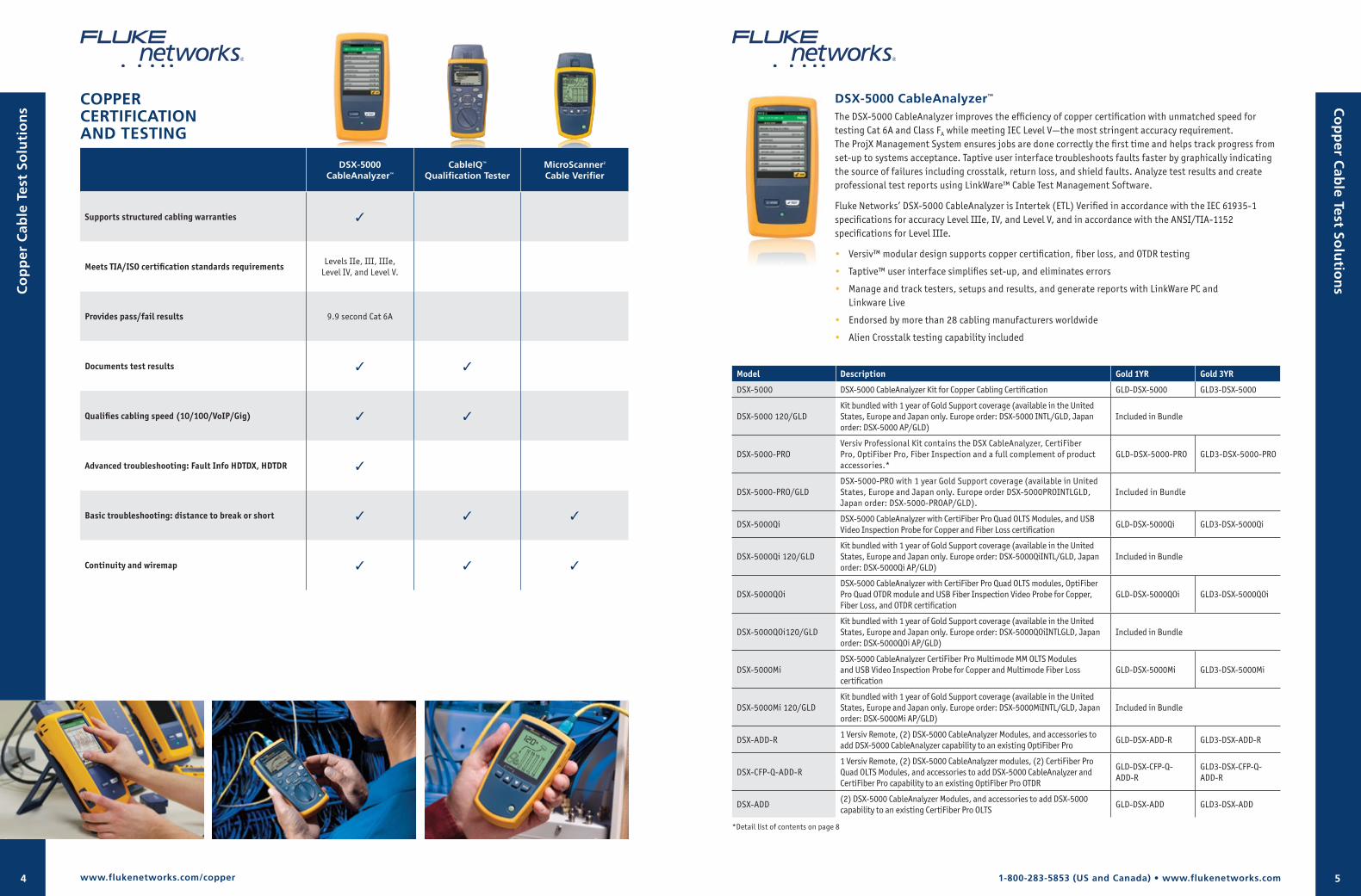
COPPER CERTIFICATION AND TESTING
DSX-5000 CableAnalyzer™
CableIQ™ Qualification Tester
MicroScanner2
Cable Verifier
Supports structured cabling warranties 3
Meets TIA/ISO certification standards requirements Levels IIe, III, IIIe, Level IV, and Level V.
Provides pass/fail results 9.9 second Cat 6A
Documents test results 3 3
Qualifies cabling speed (10/100/VoIP/Gig) 3 3
Advanced troubleshooting: Fault Info HDTDX, HDTDR 3
Basic troubleshooting: distance to break or short 3 3 3
Continuity and wiremap 3 3 3
Co
pp
er Cab
le Test Solu
tion
s
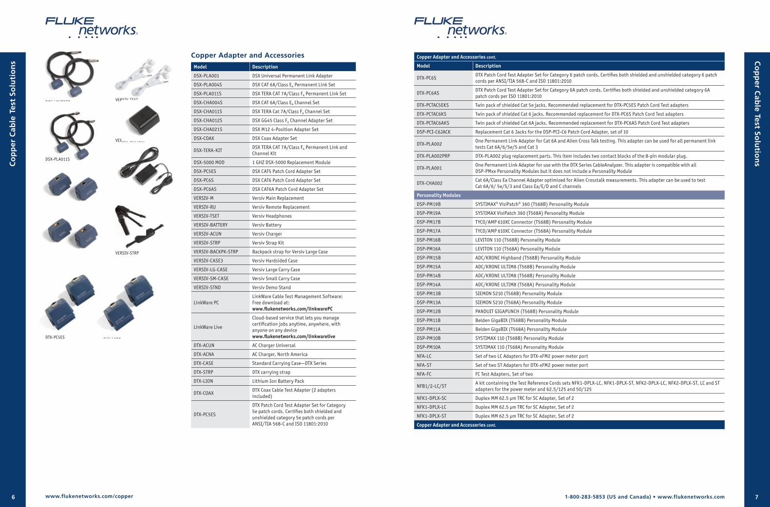
DSX-5000 CableAnalyzer™ The DSX-5000 CableAnalyzer improves the efficiency of copper certification with unmatched speed for testing Cat 6A and Class FA while meeting IEC Level V—the most stringent accuracy requirement. The ProjX Management System ensures jobs are done correctly the first time and helps track progress from set-up to systems acceptance. Taptive user interface troubleshoots faults faster by graphically indicating the source of failures including crosstalk, return loss, and shield faults. Analyze test results and create professional test reports using LinkWare™ Cable Test Management Software.
Fluke Networks’ DSX-5000 CableAnalyzer is Intertek (ETL) Verified in accordance with the IEC 61935-1 specifications for accuracy Level IIIe, IV, and Level V, and in accordance with the ANSI/TIA-1152 specifications for Level IIIe.
• Versiv™ modular design supports copper certification, fiber loss, and OTDR testing
• Taptive™ user interface simplifies set-up, and eliminates errors
• Manage and track testers, setups and results, and generate reports with LinkWare PC and Linkware Live
• Endorsed by more than 28 cabling manufacturers worldwide
• Alien Crosstalk testing capability included
Model Description Gold 1YR Gold 3YR
DSX-5000 DSX-5000 CableAnalyzer Kit for Copper Cabling Certification GLD-DSX-5000 GLD3-DSX-5000
DSX-5000 120/GLDKit bundled with 1 year of Gold Support coverage (available in the United States, Europe and Japan only. Europe order: DSX-5000 INTL/GLD, Japan order: DSX-5000 AP/GLD)
Included in Bundle
DSX-5000-PROVersiv Professional Kit contains the DSX CableAnalyzer, CertiFiber Pro, OptiFiber Pro, Fiber Inspection and a full complement of product accessories.*
GLD-DSX-5000-PRO GLD3-DSX-5000-PRO
DSX-5000-PRO/GLDDSX-5000-PRO with 1 year Gold Support coverage (available in United States, Europe and Japan only. Europe order DSX-5000PROINTLGLD, Japan order: DSX-5000-PROAP/GLD).
Included in Bundle
DSX-5000QiDSX-5000 CableAnalyzer with CertiFiber Pro Quad OLTS Modules, and USB Video Inspection Probe for Copper and Fiber Loss certification
GLD-DSX-5000Qi GLD3-DSX-5000Qi
DSX-5000Qi 120/GLDKit bundled with 1 year of Gold Support coverage (available in the United States, Europe and Japan only. Europe order: DSX-5000QiINTL/GLD, Japan order: DSX-5000Qi AP/GLD)
Included in Bundle
DSX-5000QOiDSX-5000 CableAnalyzer with CertiFiber Pro Quad OLTS modules, OptiFiber Pro Quad OTDR module and USB Fiber Inspection Video Probe for Copper, Fiber Loss, and OTDR certification
GLD-DSX-5000QOi GLD3-DSX-5000QOi
DSX-5000QOi120/GLDKit bundled with 1 year of Gold Support coverage (available in the United States, Europe and Japan only. Europe order: DSX-5000QOiINTLGLD, Japan order: DSX-5000QOi AP/GLD)
Included in Bundle
DSX-5000MiDSX-5000 CableAnalyzer CertiFiber Pro Multimode MM OLTS Modules and USB Video Inspection Probe for Copper and Multimode Fiber Loss certification
GLD-DSX-5000Mi GLD3-DSX-5000Mi
DSX-5000Mi 120/GLDKit bundled with 1 year of Gold Support coverage (available in the United States, Europe and Japan only. Europe order: DSX-5000MiINTL/GLD, Japan order: DSX-5000Mi AP/GLD)
Included in Bundle
DSX-ADD-R1 Versiv Remote, (2) DSX-5000 CableAnalyzer Modules, and accessories to add DSX-5000 CableAnalyzer capability to an existing OptiFiber Pro
GLD-DSX-ADD-R GLD3-DSX-ADD-R
DSX-CFP-Q-ADD-R1 Versiv Remote, (2) DSX-5000 CableAnalyzer modules, (2) CertiFiber Pro Quad OLTS Modules, and accessories to add DSX-5000 CableAnalyzer and CertiFiber Pro capability to an existing OptiFiber Pro OTDR
GLD-DSX-CFP-Q-ADD-R
GLD3-DSX-CFP-Q-ADD-R
DSX-ADD(2) DSX-5000 CableAnalyzer Modules, and accessories to add DSX-5000 capability to an existing CertiFiber Pro OLTS
GLD-DSX-ADD GLD3-DSX-ADD
*Detail list of contents on page 8
www.flukenetworks.com/copper
Co
pp
er C
able
Tes
t So
luti
on
s
1-800-283-5853 (US and Canada) • www.flukenetworks.com6 7
Co
pp
er Cab
le Test Solu
tion
s
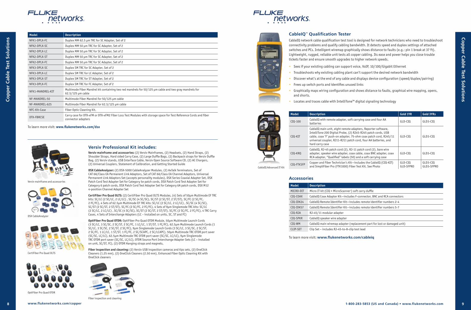
Copper Adapter and Accessories
Model Description
DSX-PLA001 DSX Universal Permanent Link Adapter
DSX-PLA004S DSX CAT 6A/Class EA Permanent Link Set
DSX-PLA011S DSX TERA CAT 7A/Class FA Permanent Link Set
DSX-CHA004S DSX CAT 6A/Class EA Channel Set
DSX-CHA011S DSX TERA Cat 7A/Class FA Channel Set
DSX-CHA012S DSX GG45 Class FA Channel Adapter Set
DSX-CHA021S DSX M12 4-Position Adapter Set
DSX-COAX DSX Coax Adapter Set
DSX-TERA-KITDSX TERA CAT 7A/Class FA Permanent Link and Channel Kit
DSX-5000 MOD 1 GHZ DSX-5000 Replacement Module
DSX-PC5ES DSX CAT5 Patch Cord Adapter Set
DSX-PC6S DSX CAT6 Patch Cord Adapter Set
DSX-PC6AS DSX CAT6A Patch Cord Adapter Set
VERSIV-M Versiv Main Replacement
VERSIV-RU Versiv Remote Replacement
VERSIV-TSET Versiv Headphones
VERSIV-BATTERY Versiv Battery
VERSIV-ACUN Versiv Charger
VERSIV-STRP Versiv Strap Kit
VERSIV-BACKPK-STRP Backpack strap for Versiv Large Case
VERSIV-CASE3 Versiv Hardsided Case
VERSIV-LG-CASE Versiv Large Carry Case
VERSIV-SM-CASE Versiv Small Carry Case
VERSIV-STND Versiv Demo Stand
LinkWare PCLinkWare Cable Test Management Software: Free download at: www.flukenetworks.com/linkwarePC
LinkWare Live
Cloud-based service that lets you manage certification jobs anytime, anywhere, with anyone on any device www.flukenetworks.com/linkwarelive
DTX-ACUN AC Charger Universal
DTX-ACNA AC Charger, North America
DTX-CASE Standard Carrying Case—DTX Series
DTX-STRP DTX carrying strap
DTX-LION Lithium Ion Battery Pack
DTX-COAXDTX Coax Cable Test Adapter (2 adapters included)
DTX-PC5ES
DTX Patch Cord Test Adapter Set for Category 5e patch cords. Certifies both shielded and unshielded category 5e patch cords per ANSI/TIA 568-C and ISO 11801:2010
DSX-PLA004S
DSX-PLA011S
DSX-CHA004S
DSX-CHA011S
VERSIV-BATTERY
VERSIV-STRP
DTX-PC5ES
VERSIV-TSET
VERSIV-ACUN
DTX-PC6S
Copper Adapter and Accessories cont.
Model Description
DTX-PC6SDTX Patch Cord Test Adapter Set for Category 6 patch cords. Certifies both shielded and unshielded category 6 patch cords per ANSI/TIA 568-C and ISO 11801:2010
DTX-PC6ASDTX Patch Cord Test Adapter Set for Category 6A patch cords. Certifies both shielded and unshielded category 6A patch cords per ISO 11801:2010
DTX-PCTAC5EKS Twin pack of shielded Cat 5e jacks. Recommended replacement for DTX-PC5ES Patch Cord Test adapters
DTX-PCTAC6KS Twin pack of shielded Cat 6 jacks. Recommended replacement for DTX-PC6S Patch Cord Test adapters
DTX-PCTAC6AKS Twin pack of shielded Cat 6A jacks. Recommended replacement for DTX-PC6AS Patch Cord Test adapters
DSP-PCI-C6JACK Replacement Cat 6 Jacks for the DSP-PCI-C6 Patch Cord Adapter, set of 10
DTX-PLA002One Permanent Link Adapter for Cat 6A and Alien Cross Talk testing. This adapter can be used for all permanent link tests Cat 6A/6/5e/5 and Cat 3
DTX-PLA002PRP DTX-PLA002 plug replacement parts. This item includes two contact blocks of the 8-pin modular plug.
DTX-PLA001One Permanent Link Adapter for use with the DTX Series CableAnalyzer. This adapter is compatible with all DSP-PMxx Personality Modules but it does not include a Personality Module
DTX-CHA002Cat 6A/Class Ea Channel Adapter optimized for Alien Crosstalk measurements. This adapter can be used to test Cat 6A/6/ 5e/5/3 and Class Ea/E/D and C channels
Personality Modules
DSP-PM19B SYSTIMAX® VisiPatch® 360 (T568B) Personality Module
DSP-PM19A SYSTIMAX VisiPatch 360 (T568A) Personality Module
DSP-PM17B TYCO/AMP 610XC Connector (T568B) Personality Module
DSP-PM17A TYCO/AMP 610XC Connector (T568A) Personality Module
DSP-PM16B LEVITON 110 (T568B) Personality Module
DSP-PM16A LEVITON 110 (T568A) Personality Module
DSP-PM15B ADC/KRONE Highband (T568B) Personality Module
DSP-PM15A ADC/KRONE ULTIM8 (T568B) Personality Module
DSP-PM14B ADC/KRONE ULTIM8 (T568B) Personality Module
DSP-PM14A ADC/KRONE ULTIM8 (T568A) Personality Module
DSP-PM13B SIEMON S210 (T568B) Personality Module
DSP-PM13A SIEMON S210 (T568A) Personality Module
DSP-PM12B PANDUIT GIGAPUNCH (T568B) Personality Module
DSP-PM11B Belden GigaBIX (T568B) Personality Module
DSP-PM11A Belden GigaBIX (T568A) Personality Module
DSP-PM10B SYSTIMAX 110 (T568B) Personality Module
DSP-PM10A SYSTIMAX 110 (T568A) Personality Module
NFA-LC Set of two LC Adapters for DTX-xFM2 power meter port
NFA-ST Set of two ST Adapters for DTX-xFM2 power meter port
NFA-FC FC Test Adapters, Set of two
NFB1/2-LC/STA kit containing the Test Reference Cords sets NFK1-DPLX-LC, NFK1-DPLX-ST, NFK2-DPLX-LC, NFK2-DPLX-ST, LC and ST adapters for the power meter and 62.5/125 and 50/125
NFK1-DPLX-SC Duplex MM 62.5 μm TRC for SC Adapter, Set of 2
NFK1-DPLX-LC Duplex MM 62.5 μm TRC for SC Adapter, Set of 2
NFK1-DPLX-ST Duplex MM 62.5 μm TRC for SC Adapter, Set of 2
Copper Adapter and Accessories cont.
www.flukenetworks.com/copper
Co
pp
er C
able
Tes
t So
luti
on
s
1-800-283-5853 (US and Canada) • www.flukenetworks.com8 9
Model Description
NFK1-DPLX-FC Duplex MM 62.5 μm TRC for SC Adapter, Set of 2
NFK2-DPLX-SC Duplex MM 50 μm TRC for SC Adapter, Set of 2
NFK2-DPLX-LC Duplex MM 50 μm TRC for SC Adapter, Set of 2
NFK2-DPLX-ST Duplex MM 50 μm TRC for SC Adapter, Set of 2
NFK2-DPLX-FC Duplex MM 50 μm TRC for SC Adapter, Set of 2
NFK3-DPLX-SC Duplex SM TRC for SC Adapter, Set of 2
NFK3-DPLX-LC Duplex SM TRC for LC Adapter, Set of 2
NFK3-DPLX-ST Duplex SM TRC for ST Adapter, Set of 2
NFK3-DPLX-FC Duplex SM TRC for FC Adapter, Set of 2
NFK1-MANDREL-KITMultimode Fiber Mandrel kit containing two red mandrels for 50/125 µm cable and two gray mandrels for 62.5/125 µm cable
NF-MANDREL-50 Multimode Fiber Mandrel for 50/125 µm cable
NF-MANDREL-625 Multimode Fiber Mandrel for 62.5/125 µm cable
NFC-Kit-Case Fiber Optic Cleaning Kit.
DTX-FBRCSECarry case for DTX-xFM or DTX-xFM2 Fiber Loss Test Modules with storage space for Test Reference Cords and fiber connector adapters
To learn more visit: www.flukenetworks.com/dsx
Co
pp
er Cab
le Test Solu
tion
s
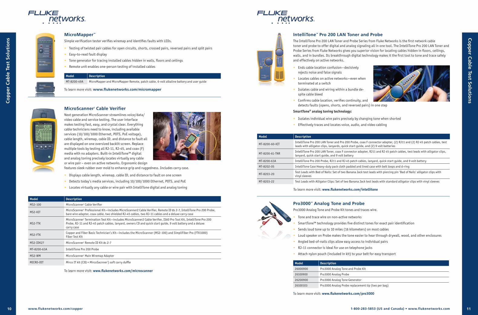
CableIQ™ Qualification TesterCableIQ network cable qualification test tool is designed for network technicians who need to troubleshoot connectivity problems and qualify cabling bandwidth. It detects speed and duplex settings of attached switches and PCs. Intelligent wiremap graphically shows distance to faults (e.g.: pin 1 break at 37 ft). Lightweight, rugged, reliable unit tests all copper cabling. Its ease and power helps you close trouble tickets faster and ensure smooth upgrades to higher network speeds.
• Sees if your existing cabling can support voice, VoIP, 10/100/Gigabit Ethernet
• Troubleshoots why existing cabling plant can’t support the desired network bandwidth
• Discover what’s at the end of any cable and displays device configuration (speed/duplex/pairing)
• Frees up switch ports and identifies unused links
• Graphically maps wiring configuration and shows distance to faults, graphical wire mapping, opens, and shorts.
• Locates and traces cable with IntelliTone™ digital signaling technology
Model Description Gold 1YR Gold 3YRs
CIQ-100CableIQ with remote adapter, soft carrying case and four AA batteries
GLD-CIQ GLD3-CIQ
CIQ-KIT
CableIQ main unit, eight remote adapters, Reporter software, IntelliTone 200 Digital Probe, (2) RJ45-RJ45 patch cords, USB cable, coax ‘F’ push-on adapter, 75-ohm coax patch cord, RJ45/11 universal coupler, RJ11-RJ11 patch cord, four AA batteries, and hard carry case
GLD-CIQ GLD3-CIQ
CIQ-KRQCableIQ, RJ-45 patch cord (2), RJ-11 patch cord (2), bare wire adapter, speaker wire adapter, coax cable, coax BNC adapter, coax RCA adapter, “Qualified” labels (50) and a soft carrying case
GLD-CIQ GLD3-CIQ
CIQ-FTKSFPCopper and Fiber Technician’s Kit—includes the CableIQ (CIQ-KIT) and SimpliFiber Pro (FTK1000) Fiber Test Kit. See Photo
GLD-CIQ GLD-SFPRO
GLD3-CIQGLD3-SFPRO
Accessories
Model Description
MICRO-DIT Micro IT kit (CIQ + MicroScanner2) soft carry duffle
CIQ-COAX CableIQ Coax Adapter Kit—includes F-connector, BNC and RCA connectors
CIQ-IDK24 CableIQ Remote Identifier Kit—includes remote identifier numbers 2-4
CIQ-IDK57 CableIQ Remote Identifier Kit—includes remote identifier numbers 5-7
CIQ-RJA RJ-45/11 modular adapter
CIQ-SPKR CableIQ speaker wire adapter
CIQ-WM CableIQ main wiremap adapter (replacement part for lost or damaged unit)
CLIP-SET Clip Set – includes RJ-45-to-8-clip test lead
To learn more visit: www.flukenetworks.com/cableiq
CableIQ Advanced IT Kit
Co
pp
er C
able
Tes
t So
luti
on
s
www.flukenetworks.com/copper
Versiv Professional Kit includes:Versiv mainframe and accessories: (2) Versiv Mainframes, (2) Headsets, (2) Hand Straps, (2) Shoulder Straps, Hard sided Carry Case, (2) Large Duffle Bags, (2) Backpack straps for Versiv Duffle Bag, (2) Versiv stands, USB Interface Cable, Versiv Open Source Software CD, (2) AC Chargers, (2) Universal Couplers, Statement of Calibration, and Getting Started Guide
DSX CableAnalyzer: (2) DSX-5000 CableAnalyzer Modules, (2) AxTalk Terminators, Set of CAT 6A/Class EA Permanent Link Adaptors, Set of CAT 6A/Class EA Channel Adaptors, Universal Permanent Link Adaptors Set (accepts personality modules), DSX Series Coaxial Adapter Set, DSX Patch Cord Test Adapter Set for Category 5e patch cords, DSX Patch Cord Test Adapter Set for Category 6 patch cords, DSX Patch Cord Test Adapter Set for Category 6A patch cords, DSX M12 4-position Channel Adapter Set
CertiFiber Pro Quad OLTS: (2) CertiFiber Pro Quad OLTS Modules, (4) Sets of 50µm Multimode EF TRC kits: SC/LC (2 SC/LC, 2 LC/LC) , SC/SC (4 SC/SC), SC/ST (2 SC/ST, 2 ST/ST), SC/FC (2 SC/FC, 2 FC/FC), 4 Sets of 62.5µm Multimode EF TRC kits: SC/LC (2 SC/LC, 2 LC/LC) , SC/SC (4 SC/SC), SC/ST (2 SC/ST, 2 ST/ST), SC/FC (2 SC/FC, 2 FC/FC), 4 Sets of 9µm Singlemode TRC kits: SC/LC (2 SC/LC, 2 LC/LC) , SC/SC (4 SC/SC), SC/ST (2 SC/ST, 2 ST/ST), SC/FC (2 SC/FC, 2 FC/FC), 4 TRC Carry Cases, 4 Sets of Interchange Adapters (LC – installed on units, SC, ST and FC)
OptiFiber Pro Quad OTDR: OptiFiber Pro Quad OTDR Module, 50µm Multimode Launch Cords (3 SC/LC, 3 SC/SC, 2 SC/ST, 2 SC/FC, 1 LC/LC, 1 ST/ST, 1 FC/FC), 62.5µm Multimode Launch Cords (1 SC/LC, 3 SC/SC, 2 SC/ST, 2 SC/FC), 9µm Singlemode Launch Cords (3 SC/LC, 3 SC/SC, 2 SC/ST, 2 SC/FC, 1 LC/LC, 1 ST/ST, 1 FC/FC, 2 SC/SCAPC, 2 SC/LCAPC), 50µm Multimode TRC OTDR port saver (SC/SC, LC/LC), 62.5µm Multimode TRC OTDR port saver (SC/SC, LC/LC), 9µm Singlemode TRC OTDR port saver (SC/SC, LC/LC), OTDR Source Port Interchange Adapter Sets (LC – installed on unit, SC/ST, FC), (2) OTDR Hanging straps and magnets,
Fiber inspection and cleaning: (2) Versiv USB inspection cameras and tips sets, (2) OneClick Cleaners (1.25 mm), (2) OneClick Cleaners (2.50 mm), Enhanced Fiber Optic Cleaning Kit with OneClick cleaners
Versiv mainframe and accessories
DSX CableAnalyzer
OptiFiber Pro Quad OTDR
Fiber inspection and cleaning
CertiFiber Pro Quad OLTS
1-800-283-5853 (US and Canada) • www.flukenetworks.com10 11
IntelliTone™ Pro 200 LAN Toner and ProbeThe IntelliTone Pro 200 LAN Toner and Probe Series from Fluke Networks is the first network cable toner and probe to offer digital and analog signaling all in one tool. The IntelliTone Pro 200 LAN Toner and Probe Series from Fluke Networks gives you superior vision for locating cables hidden in floors, ceilings, walls, and in bundles. Its breakthrough digital technology makes it the first tool to tone and trace safely and effectively on active networks.
• Ends cable location confusion—decisively rejects noise and false signals
• Locates cables on active networks—even when terminated at a switch
• Isolates cable and wiring within a bundle de-spite cable bleed
• Confirms cable location, verifies continuity, and detects faults (opens, shorts, and reversed pairs) in one step
SmartTone® analog toning technology:
• Isolates individual wire pairs precisely by changing tone when shorted
• Effectively traces and locates voice, audio, and video cabling
MicroMapper™
Simple verification tester verifies wiremap and identifies faults with LEDs.
• Testing of twisted pair cables for open circuits, shorts, crossed pairs, reversed pairs and split pairs
• Easy-to-read fault display
• Tone generator for tracing installed cables hidden in walls, floors and ceilings
• Remote unit enables one-person testing of installed cables
Model Description
MT-8200-49A MicroMapper and MicroMapper Remote, patch cable, 6-volt alkaline battery and user guide
To learn more visit: www.flukenetworks.com/micromapper
MicroScanner2 Cable VerifierNext generation MicroScanner streamlines voice/data/video cable and service testing. The user interface makes testing fast, easy, and crystal clear. Everything cable technicians need to know, including available services (10/100/1000 Ethernet, POTS, PoE voltage), cable length, wiremap, cable ID, and distance to fault all are displayed on one oversized backlit screen. Replace multiple tools by testing all RJ-11, RJ-45, and coax (F) media with no adapters. Built-in IntelliTone™ digital and analog toning precisely locates virtually any cable or wire pair – even on active networks. Ergonomic design features sleek rubber over mold to enhance grip and ruggedness. Includes carry case.
• Displays cable length, wiremap, cable ID, and distance to fault on one screen
• Detects today’s media services, including 10/100/1000 Ethernet, POTS, and PoE
• Locates virtually any cable or wire pair with IntelliTone digital and analog toning
www.flukenetworks.com/copper
Co
pp
er C
able
Tes
t So
luti
on
s Co
pp
er Cab
le Test Solu
tion
s
Model Description
MS2-100 MicroScanner2 Cable Verifier
MS2-KITMicroScanner2 Professional Kit—includes MicroScanner2 Cable Verifier, Remote ID #s 2-7, IntelliTone Pro 200 Probe, bare wire adapter, coax cable, two shielded RJ-45 cables, two RJ-11 cables and a deluxe carry case
MS2-TTKMicroScanner2 Termination Test Kit—includes MicroScanner2 Cable Verifier, IS60 Pro Tool Kit, IntelliTone Pro 200 Probe, RJ-11 and RJ-45 patch cables, lanyard, owners CD and quick start guide, 9 volt battery and a deluxe carry case
MS2-FTKCopper and Fiber Basic Technician’s Kit—includes the MicroScanner (MS2-100) and SimpliFiber Pro (FTK1000) Fiber Test Kit
MS2-IDK27 MicroScanner2 Remote ID Kit #s 2-7
MT-8200-63A IntelliTone Pro 200 Probe
MS2-WM MicroScanner2 Main Wiremap Adapter
MICRO-DIT Mirco IT kit (CIQ + MircoSacnner2) soft carry duffle
Model Description
MT-8200-60-KITIntelliTone Pro 200 LAN Toner and Pro 200 Probe, coax F connector adapter, (2) RJ11 and (2) RJ 45 patch cables, test leads with alligator clips, lanyards, quick start guide, and (2) 9 volt batteries
MT-8200-61-TNRIntelliTone Pro 200 LAN Toner, coax F connector adapter, RJ11 and RJ 45 patch cables, test leads with alligator clips, lanyard, quick start guide, and 9 volt battery
MT-8200-63A IntelliTone Pro 200 Probe, RJ11 and RJ 45 patch cables, lanyard, quick start guide, and 9 volt battery
MT-8202-05 IntelliTone Case Heavy-duty pack cloth padded and lined case with belt loops and d-ring
MT-8203-20Test Leads with Bed of Nails: Set of two Banana Jack test leads with piercing pin ‘Bed of Nails’ alligator clips with vinyl sleeves
MT-8203-22 Test Leads with Alligator Clips: Set of two Banana Jack test leads with standard alligator clips with vinyl sleeves
Pro3000™ Analog Tone and ProbePro3000 Analog Tone and Probe Kit tones and traces wire.
• Tone and trace wire on non-active networks
• SmartTone™ technology provides five distinct tones for exact pair identification
• Sends loud tone up to 10 miles (16 kilometers) on most cables
• Loud speaker on Probe makes the tone easier to hear through drywall, wood, and other enclosures
• Angled bed-of-nails clips allow easy access to individual pairs
• RJ-11 connector is ideal for use on telephone jacks
• Attach nylon pouch (included in kit) to your belt for easy transport
Model Description
26000900 Pro3000 Analog Tone and Probe Kit
26100900 Pro3000 Analog Probe
26200900 Pro3000 Analog Tone Generator
26100103 Pro3000 Analog Probe replacement tip (two per bag)
To learn more visit: www.flukenetworks.com/microscanner
To learn more visit: www.flukenetworks.com/intellitone
To learn more visit: www.flukenetworks.com/pro3000
1-800-283-5853 (US and Canada) • www.flukenetworks.com12 13
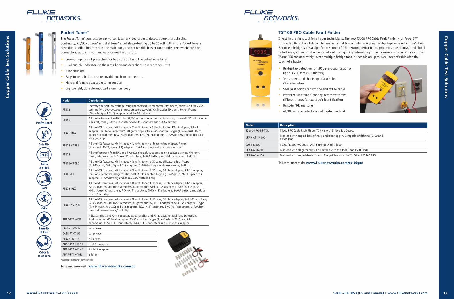
Pocket Toner®
The Pocket Toner® connects to any voice, data, or video cable to detect open/short circuits, continuity, AC/DC voltage* and dial tone* all while protecting up to 52 volts. All of the Pocket Toners have dual audible indicators in the main body and detachable buzzer toner units, removable push on connectors, auto shut-off and easy-to-read indicators.
• Low-voltage circuit protection for both the unit and the detachable toner
• Dual audible indicators in the main body and detachable buzzer toner units
• Auto shut-off
• Easy-to-read indicators; removable push-on connectors
• Male and female adaptable toner section
• Lightweight, durable anodized aluminum body
Model Description
PTNX1Identify and test low-voltage, singular coax cables for continuity, opens/shorts and 50-75 Ω termination. Low-voltage protection up to 52 volts. Kit includes NX1 unit, toner, F-type (M-push, Speed 81™) adapters and 1-AAA battery
PTNX2All the features of the NX1 plus AC/DC voltage detection- all in an easy-to-read LCD. Kit includes NX2 unit, toner, F-type (M-push, Speed 81) adapters and 1-AAA battery
PTNX2-DLX
All the NX2 features. Kit includes NX2 unit, toner, 66 block adapter, RJ-11 adapter, RJ-45 adapter, Dial Tone Detective™, alligator clips with RJ-45 adapter, F-type (F, 9-M-push, M-71, Speed 81) adapters, RCA (M, F) adapters, BNC (M, F) adapters, 1-AAA battery and deluxe case with belt clip
PTNX2-CABLEAll the NX2 features. Kit includes NX2 unit, toner, alligator clips adapter, F-type (F, M-push, M-71, Speed 81) adapters, 1-AAA battery and small canvas case
PTNX8All the features of the NX1 and NX2 plus the ability to test up to 8 cables at once. NX8 unit, toner, F-type (M-push, Speed 81) adapters, 1-AAA battery and deluxe case with belt clip
PTNX8-CABLEAll the NX8 features. Kit includes NX8 unit, toner, 8 ID caps, alligator clips, F-type (F, 9-M-push, M-71, Speed 81) adapters, 1-AAA battery and deluxe case w/ belt clip
PTNX8-CTAll the NX8 features. Kit includes NX8 unit, toner, 8 ID caps, 66 block adapter, RJ-11 adapter, Dial Tone Detective, alligator clips with RJ-11 adapter, F-type (F, 9-M-push, M-71, Speed 81) adapters, 1-AAA battery and deluxe case with belt clip
PTNX8-DLX
All the NX8 features. Kit includes NX8 unit, toner, 8 ID caps, 66 block adapter, RJ-11 adapter, RJ-45 adapter, Dial Tone Detective, alligator clips with RJ-45 adapter, F-type (F, 9-M-push, M-71, Speed 81) adapters, RCA (M, F) adapters, BNC (M, F) adapters, 1-AAA battery and deluxe case w/ belt clip
PTNX8-VV-PRO
All the NX8 features. Kit includes NX8 unit, toner, 8 ID caps, 66 block adapter, 8-RJ-11 adapters, RJ-45 adapter, Dial Tone Detective, alligator clips w/ RJ-11 adapter and RJ-45 adapter, F-type (F, 9-M-push, M-71, Speed 81) adapters, RCA (M, F) adapters, BNC (M, F) adapters, 1-AAA bat-tery and deluxe case w/ belt clip
ADAP-PTNX-KITAlligator clips and RJ-45 adapter, alligator clips and RJ-11 adapter, Dial Tone Detective, RJ-11 adapter, 66 block adapter, RJ-45 adapter, F-type (F, M-Push, M-71, Speed 81) connectors, RCA (M, F) connectors, BNC (M, F) connectors and 2-wire clip adapter
CASE-PTNX-SM Small case
CASE-PTNX-LG Large case
PTNX8-ID-1-8 8-ID caps
ADAP-PTNX-RJ11 8 RJ-11 adapters
ADAP-PTNX-RJ45 8 RJ-45 adapters
ADAP-PTNX-TNR 1 Toner
*Varies by model/kit configuration
To learn more visit: www.flukenetworks.com/pt
CableProfessional
Satellite
Audio& Video
LAN
Voice
Security& Fire
Cable & Telephone
www.flukenetworks.com/copper
Co
pp
er Cab
le Test Solu
tion
s
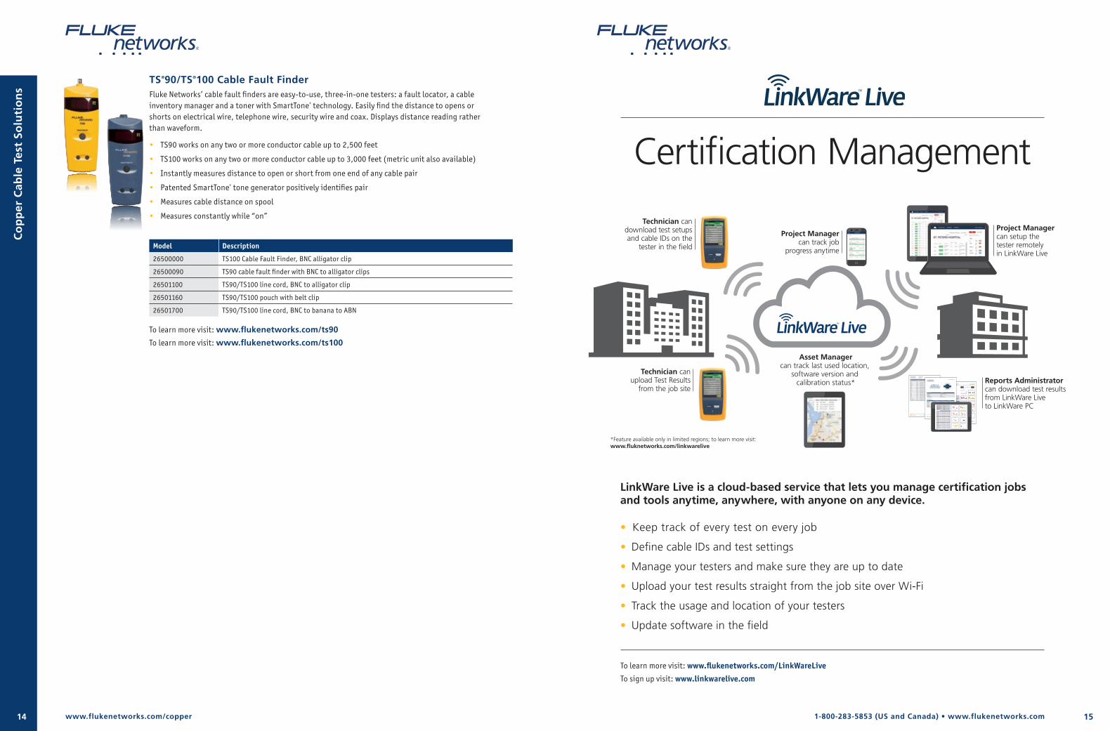
TS®100 PRO Cable Fault FinderInvest in the right tool for all your technicians. The new TS100 PRO Cable Fault Finder with PowerBT™ Bridge Tap Detect is a telecom technician’s first line of defense against bridge taps on a subscriber’s line. Because a bridge tap is a significant source of DSL network performance problems due to unwanted signal reflectance, it needs to be identified and fixed quickly before the problem causes customer attrition. The TS100 PRO can accurately locate multiple bridge taps in seconds on up to 3,200 feet of cable with the touch of a button.
• Bridge tap detection for xDSL pre-qualification on up to 3,200 feet (975 meters)
• Tests opens and shorts up to 8,000 feet (2.4 kilometers)
• Sees past bridge taps to the end of the cable
• Patented SmartTone® tone generator with five different tones for exact pair identification
• Built-in TDR and toner
• AC/DC voltage detection and digital read out
Co
pp
er C
able
Tes
t So
luti
on
s
Model Description
TS100-PRO-BT-TDR TS100 PRO Cable Fault Finder TDR Kit with Bridge Tap Detect
LEAD-ABNP-100Test lead with angled-bed-of-nails and piercing pin. Compatible with the TS100 and TS100 PRO
CASE-TS100 TS100/TS100PRO pouch with Fluke Networks’ logo
LEAD-ALIG-100 Test lead with alligator clips. Compatible with the TS100 and TS100 PRO
LEAD-ABN-100 Test lead with angled-bed-of-nails. Compatible with the TS100 and TS100 PRO
To learn more visit: www.flukenetworks.com/ts100pro
151-800-283-5853 (US and Canada) • www.flukenetworks.com14
LinkWare Live is a cloud-based service that lets you manage certification jobs and tools anytime, anywhere, with anyone on any device.
• Keep track of every test on every job
• Define cable IDs and test settings
• Manage your testers and make sure they are up to date
• Upload your test results straight from the job site over Wi-Fi
• Track the usage and location of your testers
• Update software in the field
TS®90/TS®100 Cable Fault FinderFluke Networks’ cable fault finders are easy-to-use, three-in-one testers: a fault locator, a cable inventory manager and a toner with SmartTone® technology. Easily find the distance to opens or shorts on electrical wire, telephone wire, security wire and coax. Displays distance reading rather than waveform.
• TS90 works on any two or more conductor cable up to 2,500 feet
• TS100 works on any two or more conductor cable up to 3,000 feet (metric unit also available)
• Instantly measures distance to open or short from one end of any cable pair
• Patented SmartTone® tone generator positively identifies pair
• Measures cable distance on spool
• Measures constantly while “on”
Model Description
26500000 TS100 Cable Fault Finder, BNC alligator clip
26500090 TS90 cable fault finder with BNC to alligator clips
26501100 TS90/TS100 line cord, BNC to alligator clip
26501160 TS90/TS100 pouch with belt clip
26501700 TS90/TS100 line cord, BNC to banana to ABN
To learn more visit: www.flukenetworks.com/ts90
To learn more visit: www.flukenetworks.com/ts100
Co
pp
er C
able
Tes
t So
luti
on
s
Certification Management
To learn more visit: www.flukenetworks.com/LinkWareLive
To sign up visit: www.linkwarelive.com
Technician candownload test setupsand cable IDs on the
tester in the field
Technician canupload Test Results
from the job site
Project Managercan track job
progress anytime
Asset Managercan track last used location,
software version and calibration status*
Project Managercan setup thetester remotelyin LinkWare Live
Reports Administratorcan download test resultsfrom LinkWare Liveto LinkWare PC
*Feature available only in limited regions; to learn more visit: www.fluknetworks.com/linkwarelive
4 of XXX
Customer LogoReport for: Client NameProject: Project TitleCable ID: FEED PORT. 1 PORT 23 Test Summary: FAIL
Date / Time: 09/01/2015 01:31:50 PM Operator: CHUCK Model: DSX-5000Headroom 11.0 dB (NEXT 12-36) Software Version: V4.3 Build 6 Main S/N: 2906257Test Limit: TIA Cat 5e Perm. Link Limits Version: V4.3 Remote S/N: 2906245Cable Type: Cat 5e U/UTP NVP: 69.0% Main Adapter: DSX-PLA004Calibration Date: 10/15/2014 Remote Adapter: DSX-PLA004
Project: KENT SCHOOL DIST PowerCom CJ Santeford Sept 2015.flw
LinkWare™ PC Version 9.4
Length (ft), Limit 295 [Pair 12] 724FProp. Delay (ns), Limit 498 [Pair 45] 1104FDelay Skew (ns), Limit 44 [Pair 45] 37Resistance (ohms) [Pair 45] 37.0
Insertion Loss Margin (dB) [Pair 45] -19.2FFrequency (MHz) [Pair 45] 100.0Limit (dB) [Pair 45] 21.0
Worst Case Margin Worst Case ValuePASS MAIN SR MAIN SRWorst Pair 12-36 36-78 12-36 36-78NEXT (dB) 11.0 11.4 11.0 11.4Freq. (MHz) 78.5 93.3 78.5 93.3Limit (dB) 34.0 32.8 34.0 32.8Worst Pair 12 36 12 36PS NEXT (dB) 11.5 11.2 11.6 11.2Freq. (MHz) 70.8 92.3 72.8 92.3Limit (dB) 31.8 29.9 31.6 29.9
PASS MAIN SR MAIN SRWorst Pair 12-36 12-36 12-78 78-12ACR-F (dB) 14.4 15.0 17.1 17.5Freq. (MHz) 36.3 36.3 96.5 96.5Limit (dB) 27.4 27.4 18.9 18.9Worst Pair 36 12 36 36PS ACR-F (dB) 15.4 15.5 17.5 17.0Freq. (MHz) 36.3 1.0 100.0 100.0Limit (dB) 24.4 55.6 15.6 15.6
N/A MAIN SR MAIN SRWorst Pair 12-36 36-78 12-45 12-45ACR-N (dB) -5.8 -6.0 -5.2 -5.6Freq. (MHz) 78.5 93.5 92.0 100.0Limit (dB) 15.7 12.6 12.9 11.3Worst Pair 36 36 45 36PS ACR-N (dB) -3.7 -6.8 -2.7 -6.8Freq. (MHz) 78.5 92.3 92.0 92.3Limit (dB) 12.7 9.8 9.9 9.8
PASS MAIN SR MAIN SRWorst Pair 78 36 78 36RL (dB) 2.5* 2.0* 2.5 5.5Freq. (MHz) 1.1 1.1 1.1 86.8Limit (dB) 19.0 19.0 19.0 12.6
724 ft
Wire Map (T568B)PASS
Insertion Loss (dB)
MHz
0
20
40
60
80
100
0 75 150 225 300
NEXT (dB)
MHz
0
20
40
60
80
100
0 75 150 225 300
NEXT @ Remote (dB)
MHz
0
20
40
60
80
100
0 75 150 225 300
ACR-F (dB)
MHz
0
20
40
60
80
100
0 75 150 225 300
ACR-F @ Remote (dB)
MHz
0
20
40
60
80
100
0 75 150 225 300
ACR-N (dB)
MHz
-80
-40
0
40
80
0 75 150 225 300
ACR-N @ Remote (dB)
MHz
-80
-40
0
40
80
0 75 150 225 300
RL (dB)
MHz
0
10
20
30
40
50
60
0 75 150 225 300
RL @ Remote (dB)
MHz
0
10
20
30
40
50
60
0 75 150 225 300
* Measurement is within the accuracy limits of the instrument.
12
36
45
78
S
12
36
45
78
S
Cable ID: FEED PORT. 1 PORT 23 Test Summary: FAILDate / Time: 09/01/2015 01:31:50 PM Operator: CHUCK Model: DSX-5000Headroom 11.0 dB (NEXT 12-36) Software Version: V4.3 Build 6 Main S/N: 2906257Test Limit: TIA Cat 5e Perm. Link Limits Version: V4.3 Remote S/N: 2906245Cable Type: Cat 5e U/UTP NVP: 69.0% Main Adapter: DSX-PLA004Calibration Date: 10/15/2014 Remote Adapter: DSX-PLA004
Project: KENT SCHOOL DIST PowerCom CJ Santeford Sept 2015.flw
LinkWare™ PC Version 9.4
Length (ft), Limit 295 [Pair 12] 724FProp. Delay (ns), Limit 498 [Pair 45] 1104FDelay Skew (ns), Limit 44 [Pair 45] 37Resistance (ohms) [Pair 45] 37.0
Insertion Loss Margin (dB) [Pair 45] -19.2FFrequency (MHz) [Pair 45] 100.0Limit (dB) [Pair 45] 21.0
Worst Case Margin Worst Case ValuePASS MAIN SR MAIN SRWorst Pair 12-36 36-78 12-36 36-78NEXT (dB) 11.0 11.4 11.0 11.4Freq. (MHz) 78.5 93.3 78.5 93.3Limit (dB) 34.0 32.8 34.0 32.8Worst Pair 12 36 12 36PS NEXT (dB) 11.5 11.2 11.6 11.2Freq. (MHz) 70.8 92.3 72.8 92.3Limit (dB) 31.8 29.9 31.6 29.9
PASS MAIN SR MAIN SRWorst Pair 12-36 12-36 12-78 78-12ACR-F (dB) 14.4 15.0 17.1 17.5Freq. (MHz) 36.3 36.3 96.5 96.5Limit (dB) 27.4 27.4 18.9 18.9Worst Pair 36 12 36 36PS ACR-F (dB) 15.4 15.5 17.5 17.0Freq. (MHz) 36.3 1.0 100.0 100.0Limit (dB) 24.4 55.6 15.6 15.6
N/A MAIN SR MAIN SRWorst Pair 12-36 36-78 12-45 12-45ACR-N (dB) -5.8 -6.0 -5.2 -5.6Freq. (MHz) 78.5 93.5 92.0 100.0Limit (dB) 15.7 12.6 12.9 11.3Worst Pair 36 36 45 36PS ACR-N (dB) -3.7 -6.8 -2.7 -6.8Freq. (MHz) 78.5 92.3 92.0 92.3Limit (dB) 12.7 9.8 9.9 9.8
PASS MAIN SR MAIN SRWorst Pair 78 36 78 36RL (dB) 2.5* 2.0* 2.5 5.5Freq. (MHz) 1.1 1.1 1.1 86.8Limit (dB) 19.0 19.0 19.0 12.6
724 ft
Wire Map (T568B)PASS
Insertion Loss (dB)
MHz
0
20
40
60
80
100
0 75 150 225 300
NEXT (dB)
MHz
0
20
40
60
80
100
0 75 150 225 300
NEXT @ Remote (dB)
MHz
0
20
40
60
80
100
0 75 150 225 300
ACR-F (dB)
MHz
0
20
40
60
80
100
0 75 150 225 300
ACR-F @ Remote (dB)
MHz
0
20
40
60
80
100
0 75 150 225 300
ACR-N (dB)
MHz
-80
-40
0
40
80
0 75 150 225 300
ACR-N @ Remote (dB)
MHz
-80
-40
0
40
80
0 75 150 225 300
RL (dB)
MHz
0
10
20
30
40
50
60
0 75 150 225 300
RL @ Remote (dB)
MHz
0
10
20
30
40
50
60
0 75 150 225 300
* Measurement is within the accuracy limits of the instrument.
[Pair 12] 724F[Pair 45] 1104F[Pair 45] 37[Pair 45] 37.0[Pair 45] -19.2F[Pair 45] 100.0[Pair 45] 21.0
Worst Case Margin Worst Case ValuePASS MAIN SR MAIN SRWorst Pair 12-36 36-78 12-36 36-78
11.0 11.4 1 1.0 11.478.5 93.3 78.5 93.334.0 32.8 34.0 32.8
Worst Pair 12 36 12 3611.5 11.2 11.6 11.270.8 92.3 72.8 92.331.8 29.9 31.6 29.9
PASS MAIN SR MAIN SRWorst Pair 12-36 12-36 12-78 78-12
14.4 15.0 17.1 17.536.3 36.3 96.5 96.527.4 27.4 18.9 18.9
Worst Pair 36 12 36 3615.4 15.5 17.5 17.036.3 1.0 100.0 100.024.4 55.6 15.6 15.6
N/A MAIN SR MAIN SRWorst Pair 12-36 36-78 12-45 12-45
-5.8 -6.0 -5.2 -5.678.5 93.5 92.0 100.015.7 12.6 12.9 11.3
Worst Pair 36 36 45 36-3.7 -6.8 -2.7 -6.878.5 92.3 92.0 92.312.7 9.8 9.9 9.8
PASS MAIN SR MAIN SRWorst Pair 78 36 78 36
2.5* 2.0* 2.5 5.51.1 1.1 1.1 86.8
19.0 19.0 19.0 12.6
Cable ID: Date/Time: 09/01/2015 01:31:50 PMHeadroom:Test Limit: Cable Type:Calibration Date: 10/15/2014Operator: Software Version: V4.3 Build 6Limits Version: V4.3NVP: 69.0%Model: DSX-5000Main S/N: 2906257Remote S/N: 2906245 Main Adapter: Remote Adapter:
Cable ID: FEED PORT. 1 PORT 23 Test Summary: FAILDate / Time: 09/01/2015 01:31:50 PM Operator: CHUCK Model: DSX-5000Headroom 11.0 dB (NEXT 12-36) Software Version: V4.3 Build 6 Main S/N: 2906257Test Limit: TIA Cat 5e Perm. Link Limits Version: V4.3 Remote S/N: 2906245Cable Type: Cat 5e U/UTP NVP: 69.0% Main Adapter: DSX-PLA004Calibration Date: 10/15/2014 Remote Adapter: DSX-PLA004
Project: KENT SCHOOL DIST PowerCom CJ Santeford Sept 2015.flw
LinkWare™ PC Version 9.4
Length (ft), Limit 295 [Pair 12] 724FProp. Delay (ns), Limit 498 [Pair 45] 1104FDelay Skew (ns), Limit 44 [Pair 45] 37Resistance (ohms) [Pair 45] 37.0
Insertion Loss Margin (dB) [Pair 45] -19.2FFrequency (MHz) [Pair 45] 100.0Limit (dB) [Pair 45] 21.0
Worst Case Margin Worst Case ValuePASS MAIN SR MAIN SRWorst Pair 12-36 36-78 12-36 36-78NEXT (dB) 11.0 11.4 11.0 11.4Freq. (MHz) 78.5 93.3 78.5 93.3Limit (dB) 34.0 32.8 34.0 32.8Worst Pair 12 36 12 36PS NEXT (dB) 11.5 11.2 11.6 11.2Freq. (MHz) 70.8 92.3 72.8 92.3Limit (dB) 31.8 29.9 31.6 29.9
PASS MAIN SR MAIN SRWorst Pair 12-36 12-36 12-78 78-12ACR-F (dB) 14.4 15.0 17.1 17.5Freq. (MHz) 36.3 36.3 96.5 96.5Limit (dB) 27.4 27.4 18.9 18.9Worst Pair 36 12 36 36PS ACR-F (dB) 15.4 15.5 17.5 17.0Freq. (MHz) 36.3 1.0 100.0 100.0Limit (dB) 24.4 55.6 15.6 15.6
N/A MAIN SR MAIN SRWorst Pair 12-36 36-78 12-45 12-45ACR-N (dB) -5.8 -6.0 -5.2 -5.6Freq. (MHz) 78.5 93.5 92.0 100.0Limit (dB) 15.7 12.6 12.9 11.3Worst Pair 36 36 45 36PS ACR-N (dB) -3.7 -6.8 -2.7 -6.8Freq. (MHz) 78.5 92.3 92.0 92.3Limit (dB) 12.7 9.8 9.9 9.8
PASS MAIN SR MAIN SRWorst Pair 78 36 78 36RL (dB) 2.5* 2.0* 2.5 5.5Freq. (MHz) 1.1 1.1 1.1 86.8Limit (dB) 19.0 19.0 19.0 12.6
724 ft
Wire Map (T568B)PASS
Insertion Loss (dB)
MHz
0
20
40
60
80
100
0 75 150 225 300
NEXT (dB)
MHz
0
20
40
60
80
100
0 75 150 225 300
NEXT @ Remote (dB)
MHz
0
20
40
60
80
100
0 75 150 225 300
ACR-F (dB)
MHz
0
20
40
60
80
100
0 75 150 225 300
ACR-F @ Remote (dB)
MHz
0
20
40
60
80
100
0 75 150 225 300
ACR-N (dB)
MHz
-80
-40
0
40
80
0 75 150 225 300
ACR-N @ Remote (dB)
MHz
-80
-40
0
40
80
0 75 150 225 300
RL (dB)
MHz
0
10
20
30
40
50
60
0 75 150 225 300
RL @ Remote (dB)
MHz
0
10
20
30
40
50
60
0 75 150 225 300
* Measurement is within the accuracy limits of the instrument.
724 ft
2 of XXX
Customer LogoReport for: Client NameProject: Project Title
Cable ID Summary Test Limit Length Headroom Date / Time 724 ft 09/01/2015 01:31 PM
725 ft 09/01/2015 01:33 PM
234 ft
234 ft
271 ft
201 ft
201 ft
75 ft
213 ft
62 ft
69 ft
79 ft
83 ft
24 ft
102 ft
103 ft
PC 2 161 ft
63 ft
79 ft
67 ft
84 ft
117 ft
134 ft
112 ft
27 ft
58 ft
101 ft 09/15/2015 01:45 PM
66 ft 09/16/2015 01:10 PM
1 of XXX
LinkWare Live Version X.X
Product Module Serial Number Firmware Version Calibration DateDSX- 5000 2405214 V4.3 Build 6 09/01/2016DSX- 5000 2420168 V4.3 Build 6 09/01/2016DSX- 5000 2420146 V4.3 Build 6 09/01/2016DSX- 5000 2420195 V4.3 Build 6 09/01/2016DSX- 5000 2420133 V4.3 Build 6 09/01/2016DSX- 5000 2420148 V4.3 Build 6 09/01/2016DSX- 5000 2420139 V4.3 Build 6 09/01/2016DSX- 5000 2420147 V4.3 Build 6 09/01/2016
Customer Logo
LinkWare Live
Report Generated Date
Exclusively for: Prepared by:Customer Name Company NameProject ID First Name & Last NameProject Name EmailProject Address AddressCity, State, Zipcode City, State, Zipcode
Structured CableCertification Report
ALL
TEST STANDARDS
H
AVE BE EN MET
5 of XXX
Customer LogoReport for: Client NameProject: Project Title
Cable ID: Date/Time: 09/01/2015 01:31:50 PMHeadroom:Test Limit: Cable Type:Calibration Date: 10/15/2014Operator: Software Version: V4.3 Build 6Limits Version: V4.3NVP: 69.0%Model: DSX-5000Main S/N: 2906257Remote S/N: 2906245 Main Adapter: Remote Adapter:
[Pair 12] 724F[Pair 45] 1104F[Pair 45] 37[Pair 45] 37.0[Pair 45] -19.2F[Pair 45] 100.0[Pair 45] 21.0
Worst Case Margin Worst Case ValuePASS MAIN SR MAIN SRWorst Pair 12-36 36-78 12-36 36-78
11.0 11.4 1 1.0 11.478.5 93.3 78.5 93.334.0 32.8 34.0 32.8
Worst Pair 12 36 12 3611.5 11.2 11.6 11.270.8 92.3 72.8 92.331.8 29.9 31.6 29.9
PASS MAIN SR MAIN SRWorst Pair 12-36 12-36 12-78 78-12
14.4 15.0 17.1 17.536.3 36.3 96.5 96.527.4 27.4 18.9 18.9
Worst Pair 36 12 36 3615.4 15.5 17.5 17.036.3 1.0 100.0 100.024.4 55.6 15.6 15.6
N/A MAIN SR MAIN SRWorst Pair 12-36 36-78 12-45 12-45
-5.8 -6.0 -5.2 -5.678.5 93.5 92.0 100.015.7 12.6 12.9 11.3
Worst Pair 36 36 45 36-3.7 -6.8 -2.7 -6.878.5 92.3 92.0 92.312.7 9.8 9.9 9.8
PASS MAIN SR MAIN SRWorst Pair 78 36 78 36
2.5* 2.0* 2.5 5.51.1 1.1 1.1 86.8
19.0 19.0 19.0 12.6
724 ft
Cable ID: FEED PORT. 1 PORT 23 Test Summary: FAILDate / Time: 09/01/2015 01:31:50 PM Operator: CHUCK Model: DSX-5000Headroom 11.0 dB (NEXT 12-36) Software Version: V4.3 Build 6 Main S/N: 2906257Test Limit: TIA Cat 5e Perm. Link Limits Version: V4.3 Remote S/N: 2906245Cable Type: Cat 5e U/UTP NVP: 69.0% Main Adapter: DSX-PLA004Calibration Date: 10/15/2014 Remote Adapter: DSX-PLA004
Project: KENT SCHOOL DIST PowerCom CJ Santeford Sept 2015.flw
LinkWare™ PC Version 9.4
Length (ft), Limit 295 [Pair 12] 724FProp. Delay (ns), Limit 498 [Pair 45] 1104FDelay Skew (ns), Limit 44 [Pair 45] 37Resistance (ohms) [Pair 45] 37.0
Insertion Loss Margin (dB) [Pair 45] -19.2FFrequency (MHz) [Pair 45] 100.0Limit (dB) [Pair 45] 21.0
Worst Case Margin Worst Case ValuePASS MAIN SR MAIN SRWorst Pair 12-36 36-78 12-36 36-78NEXT (dB) 11.0 11.4 11.0 11.4Freq. (MHz) 78.5 93.3 78.5 93.3Limit (dB) 34.0 32.8 34.0 32.8Worst Pair 12 36 12 36PS NEXT (dB) 11.5 11.2 11.6 11.2Freq. (MHz) 70.8 92.3 72.8 92.3Limit (dB) 31.8 29.9 31.6 29.9
PASS MAIN SR MAIN SRWorst Pair 12-36 12-36 12-78 78-12ACR-F (dB) 14.4 15.0 17.1 17.5Freq. (MHz) 36.3 36.3 96.5 96.5Limit (dB) 27.4 27.4 18.9 18.9Worst Pair 36 12 36 36PS ACR-F (dB) 15.4 15.5 17.5 17.0Freq. (MHz) 36.3 1.0 100.0 100.0Limit (dB) 24.4 55.6 15.6 15.6
N/A MAIN SR MAIN SRWorst Pair 12-36 36-78 12-45 12-45ACR-N (dB) -5.8 -6.0 -5.2 -5.6Freq. (MHz) 78.5 93.5 92.0 100.0Limit (dB) 15.7 12.6 12.9 11.3Worst Pair 36 36 45 36PS ACR-N (dB) -3.7 -6.8 -2.7 -6.8Freq. (MHz) 78.5 92.3 92.0 92.3Limit (dB) 12.7 9.8 9.9 9.8
PASS MAIN SR MAIN SRWorst Pair 78 36 78 36RL (dB) 2.5* 2.0* 2.5 5.5Freq. (MHz) 1.1 1.1 1.1 86.8Limit (dB) 19.0 19.0 19.0 12.6
724 ft
Wire Map (T568B)PASS
Insertion Loss (dB)
MHz
0
20
40
60
80
100
0 75 150 225 300
NEXT (dB)
MHz
0
20
40
60
80
100
0 75 150 225 300
NEXT @ Remote (dB)
MHz
0
20
40
60
80
100
0 75 150 225 300
ACR-F (dB)
MHz
0
20
40
60
80
100
0 75 150 225 300
ACR-F @ Remote (dB)
MHz
0
20
40
60
80
100
0 75 150 225 300
ACR-N (dB)
MHz
-80
-40
0
40
80
0 75 150 225 300
ACR-N @ Remote (dB)
MHz
-80
-40
0
40
80
0 75 150 225 300
RL (dB)
MHz
0
10
20
30
40
50
60
0 75 150 225 300
RL @ Remote (dB)
MHz
0
10
20
30
40
50
60
0 75 150 225 300
* Measurement is within the accuracy limits of the instrument.
12
36
45
78
S
12
36
45
78
S
Cable ID: FEED PORT. 1 PORT 23 Test Summary: FAILDate / Time: 09/01/2015 01:31:50 PM Operator: CHUCK Model: DSX-5000Headroom 11.0 dB (NEXT 12-36) Software Version: V4.3 Build 6 Main S/N: 2906257Test Limit: TIA Cat 5e Perm. Link Limits Version: V4.3 Remote S/N: 2906245Cable Type: Cat 5e U/UTP NVP: 69.0% Main Adapter: DSX-PLA004Calibration Date: 10/15/2014 Remote Adapter: DSX-PLA004
Project: KENT SCHOOL DIST PowerCom CJ Santeford Sept 2015.flw
LinkWare™ PC Version 9.4
Length (ft), Limit 295 [Pair 12] 724FProp. Delay (ns), Limit 498 [Pair 45] 1104FDelay Skew (ns), Limit 44 [Pair 45] 37Resistance (ohms) [Pair 45] 37.0
Insertion Loss Margin (dB) [Pair 45] -19.2FFrequency (MHz) [Pair 45] 100.0Limit (dB) [Pair 45] 21.0
Worst Case Margin Worst Case ValuePASS MAIN SR MAIN SRWorst Pair 12-36 36-78 12-36 36-78NEXT (dB) 11.0 11.4 11.0 11.4Freq. (MHz) 78.5 93.3 78.5 93.3Limit (dB) 34.0 32.8 34.0 32.8Worst Pair 12 36 12 36PS NEXT (dB) 11.5 11.2 11.6 11.2Freq. (MHz) 70.8 92.3 72.8 92.3Limit (dB) 31.8 29.9 31.6 29.9
PASS MAIN SR MAIN SRWorst Pair 12-36 12-36 12-78 78-12ACR-F (dB) 14.4 15.0 17.1 17.5Freq. (MHz) 36.3 36.3 96.5 96.5Limit (dB) 27.4 27.4 18.9 18.9Worst Pair 36 12 36 36PS ACR-F (dB) 15.4 15.5 17.5 17.0Freq. (MHz) 36.3 1.0 100.0 100.0Limit (dB) 24.4 55.6 15.6 15.6
N/A MAIN SR MAIN SRWorst Pair 12-36 36-78 12-45 12-45ACR-N (dB) -5.8 -6.0 -5.2 -5.6Freq. (MHz) 78.5 93.5 92.0 100.0Limit (dB) 15.7 12.6 12.9 11.3Worst Pair 36 36 45 36PS ACR-N (dB) -3.7 -6.8 -2.7 -6.8Freq. (MHz) 78.5 92.3 92.0 92.3Limit (dB) 12.7 9.8 9.9 9.8
PASS MAIN SR MAIN SRWorst Pair 78 36 78 36RL (dB) 2.5* 2.0* 2.5 5.5Freq. (MHz) 1.1 1.1 1.1 86.8Limit (dB) 19.0 19.0 19.0 12.6
724 ft
Wire Map (T568B)PASS
Insertion Loss (dB)
MHz
0
20
40
60
80
100
0 75 150 225 300
NEXT (dB)
MHz
0
20
40
60
80
100
0 75 150 225 300
NEXT @ Remote (dB)
MHz
0
20
40
60
80
100
0 75 150 225 300
ACR-F (dB)
MHz
0
20
40
60
80
100
0 75 150 225 300
ACR-F @ Remote (dB)
MHz
0
20
40
60
80
100
0 75 150 225 300
ACR-N (dB)
MHz
-80
-40
0
40
80
0 75 150 225 300
ACR-N @ Remote (dB)
MHz
-80
-40
0
40
80
0 75 150 225 300
RL (dB)
MHz
0
10
20
30
40
50
60
0 75 150 225 300
RL @ Remote (dB)
MHz
0
10
20
30
40
50
60
0 75 150 225 300
* Measurement is within the accuracy limits of the instrument.
www.flukenetworks.com/copper
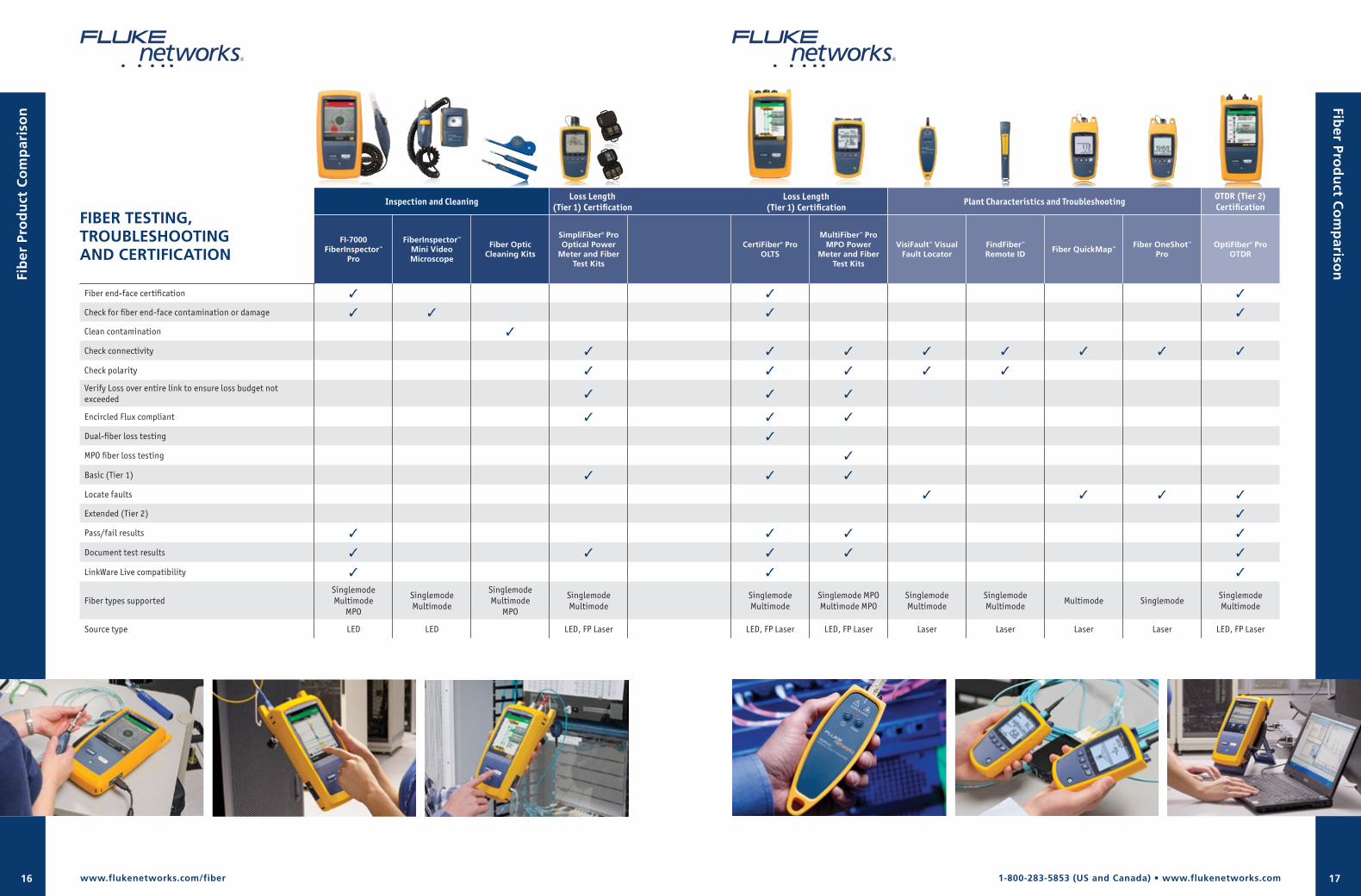
1-800-283-5853 (US and Canada) • www.flukenetworks.com16 17
FIBER TESTING, TROUBLESHOOTING AND CERTIFICATION
Inspection and Cleaning Plant Characteristics and Troubleshooting OTDR (Tier 2) Certification
FI-7000 FiberInspector™
Pro
FiberInspector™ Mini Video Microscope
Fiber Optic Cleaning Kits
SimpliFiber® Pro Optical Power
Meter and Fiber Test Kits
CertiFiber® Pro OLTS
MultiFiber™ Pro MPO Power
Meter and Fiber Test Kits
VisiFault™ Visual Fault Locator
FindFiber™ Remote ID
Fiber QuickMap™ Fiber OneShot™ Pro
OptiFIber® Pro OTDR
Fiber end-face certification 3 3 3
Check for fiber end-face contamination or damage 3 3 3 3
Clean contamination 3
Check connectivity 3 3 3 3 3 3 3 3
Check polarity 3 3 3 3 3
Verify Loss over entire link to ensure loss budget not exceeded 3 3 3
Encircled Flux compliant 3 3 3
Dual-fiber loss testing 3
MPO fiber loss testing 3
Basic (Tier 1) 3 3 3
Locate faults 3 3 3 3
Extended (Tier 2) 3
Pass/fail results 3 3 3 3
Document test results 3 3 3 3 3
LinkWare Live compatibility 3 3 3
Fiber types supportedSinglemodeMultimode
MPO
SinglemodeMultimode
SinglemodeMultimode
MPO
SinglemodeMultimode
SinglemodeMultimode
Singlemode MPOMultimode MPO
SinglemodeMultimode
SinglemodeMultimode
Multimode SinglemodeSinglemodeMultimode
Source type LED LED LED, FP Laser LED, FP Laser LED, FP Laser Laser Laser Laser Laser LED, FP Laser
www.flukenetworks.com/fiber
Fib
er P
rod
uct
Co
mp
aris
on
Fiber Pro
du
ct Co
mp
arison
Loss Length(Tier 1) Certification
Loss Length(Tier 1) Certification
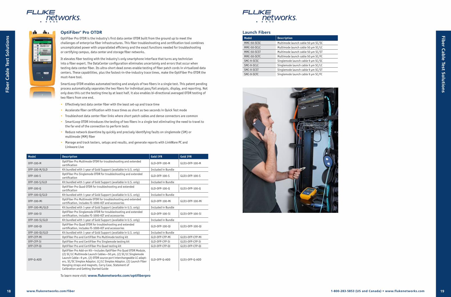
1-800-283-5853 (US and Canada) • www.flukenetworks.com18 19
OptiFiber® Pro OTDROptiFiber Pro OTDR is the industry’s first data center OTDR built from the ground up to meet the challenges of enterprise fiber infrastructures. This fiber troubleshooting and certification tool combines uncomplicated power with unparalleled efficiency and the exact functions needed for troubleshooting or certifying campus, data center and storage fiber networks.
It elevates fiber testing with the industry’s only smartphone interface that turns any technician into a fiber expert. The DataCenter configuration eliminates uncertainty and errors that occur when testing data center fiber. Its ultra-short dead zones enable testing of fiber patch cords in virtualized data centers. These capabilities, plus the fastest-in-the-industry trace times, make the OptiFiber Pro OTDR the must-have tool.
SmartLoop OTDR enables automated testing and analysis of two fibers in a single test. This patent pending process automatically separates the two fibers for individual pass/fail analysis, display, and reporting. Not only does this cut the testing time by at least half, it also enables bi-directional averaged OTDR testing of two fibers from one end.
• Effectively test data center fiber with the least set-up and trace time
• Accelerate fiber certification with trace times as short as two seconds in Quick Test mode
• Troubleshoot data center fiber links where short patch cables and dense connectors are common
• SmartLoop OTDR introduces the testing of two fibers in a single test eliminating the need to travel to the far end of the connection to perform tests
• Reduce network downtime by quickly and precisely identifying faults on singlemode (SM) or multimode (MM) fiber
• Manage and track testers, setups and results, and generate reports with LinkWare PC and Linkware Live
Model Description Gold 1YR Gold 3YR
OFP-100-MOptiFiber Pro Multimode OTDR for troubleshooting and extended certification
GLD-OFP-100-M GLD3-OFP-100-M
OFP-100-M/GLD Kit bundled with 1-year of Gold Support (available in U.S. only) Included in Bundle
OFP-100-SOptiFiber Pro Singlemode OTDR for troubleshooting and extended certification
GLD-OFP-100-S GLD3-OFP-100-S
OFP-100-S/GLD Kit bundled with 1-year of Gold Support (available in U.S. only) Included in Bundle
OFP-100-QOptiFiber Pro Quad OTDR for troubleshooting and extended certification
GLD-OFP-100-Q GLD3-OFP-100-Q
OFP-100-Q/GLD Kit bundled with 1-year of Gold Support (available in U.S. only) Included in Bundle
OFP-100-MiOptiFiber Pro Multimode OTDR for troubleshooting and extended certification, includes FI-1000-KIT and accessories
GLD-OFP-100-Mi GLD3-OFP-100-Mi
OFP-100-Mi/GLD Kit bundled with 1-year of Gold Support (available in U.S. only) Included in Bundle
OFP-100-SiOptiFiber Pro Singlemode OTDR for troubleshooting and extended certification, includes FI-1000-KIT and accessories
GLD-OFP-100-Si GLD3-OFP-100-Si
OFP-100-Si/GLD Kit bundled with 1-year of Gold Support (available in U.S. only) Included in Bundle
OFP-100-QiOptiFiber Pro Quad OTDR for troubleshooting and extended certification, includes FI-1000-KIT and accessories
GLD-OFP-100-Qi GLD3-OFP-100-Qi
OFP-100-Qi/GLD Kit bundled with 1-year of Gold Support (available in U.S. only) Included in Bundle
OFP-CFP-Mi OptiFiber Pro and CertiFiber Pro Multimode testing kit GLD-OFP-CFP-Mi GLD3-OFP-CFP-Mi
OFP-CFP-Si OptiFiber Pro and CertiFiber Pro Singlemode testing kit GLD-OFP-CFP-Si GLD3-OFP-CFP-Si
OFP-CFP-Qi OptiFiber Pro and CertiFiber Pro Quad testing kit GLD-OFP-CFP-Qi GLD3-OFP-CFP-Qi
OFP-Q-ADD
OptiFiber Pro Add-on Kit—includes OptiFiber Pro Quad OTDR Module, (2) SC/LC Multimode Launch Cables—50 µm, (2) SC/LC Singlemode Launch Cable—9 µm, (2) OTDR source port interchangeable LC adapt-ers, SC/SC Simplex Adaptor, LC/LC Simplex Adaptor, (2) Launch Fiber Hanging straps and magnets, Carry Case, Statement of Calibration and Getting Started Guide
GLD-OFP-Q-ADD GLD3-OFP-Q-ADD
Launch FibersModel Description
MMC-50-SCSC Multimode launch cable 50 µm SC/SC
MMC-50-SCLC Multimode launch cable 50 µm SC/LC
MMC-50-SCST Multimode launch cable 50 µm SC/ST
MMC-50-SCFC Multimode launch cable 50 µm SC/FC
SMC-9-SCSC Singlemode launch cable 9 µm SC/SC
SMC-9-SCLC Singlemode launch cable 9 µm SC/LC
SMC-9-SCST Singlemode launch cable 9 µm SC/ST
SMC-9-SCFC Singlemode launch cable 9 µm SC/FC
www.flukenetworks.com/fiber
Fib
er C
able
Tes
t So
luti
on
s Fiber C
able Test So
lutio
ns
To learn more visit: www.flukenetworks.com/optifiberpro
1-800-283-5853 (US and Canada) • www.flukenetworks.com20 21
CertiFiber® ProCertiFiber Pro OLTS improves the efficiency of fiber certification with a 3-second, two-fibers-at-both- wave-lengths test. The Taptive user interface simplifies set-up, eliminates errors and speeds troubleshooting. A set reference wizard ensures correct reference setting and eliminates negative loss errors. Built on the future-ready Versiv platform, CertiFiber Pro provides merged Tier 1 (Basic) / Tier 2 (Extended) testing and reporting when paired with OptiFiber Pro module. A convenient quad module supports both singlemode and multimode and is multimode Encircled Flux compliant. Manage and track testers, setups and results, and generate reports with LinkWare PC and Linkware Live.
CertiFiber Pro’s double ended fiber optic inspection capability allows you to inspect and certify fiber optic connector end-faces at both ends of your fiber link in less than a second so you can get your job done the first time. This double ended fiber optic inspection capability provides automated PASS/FAIL certification, takes the guess work out of fiber inspection so anyone can be a fiber expert.
• Taptive™ user interface provides simple, animated guidance to eliminate incorrect reference setup and “negative loss” errors
• Fastest time to certify—two fibers at two wavelengths in three seconds
• Encircled Flux compliant as required by ANSI/TIA and ISO/IEC
• Double ended Pass/Fail certification of fiber optic connector endfaces
• Merged Tier 1 (Basic) / Tier 2 (Extended) testing and reporting when paired with OptiFiber Pro
• ProjX™ management system ensures all jobs are completed correctly and efficiently
• Convenient quad module supports both multimode and singlemode loss testing
• Extended singlemode distance range to 130 km
• Built-in Visual Fault Locator
Model Description Gold 1YR Gold 3YR
CFP-100-Q CertiFiber Pro Quad Testing Kit GLD-CFP-100-Q GLD3-CFP-100-Q
CFP-100-M CertiFiber Pro Multimode Testing Kit GLD-CFP-100-M GLD3-CFP-100-M
CFP-100-S CertiFiber Pro Singlemode Testing Kit GLD-CFP-100-S GLD3-CFP-100-S
OFP-CFP-Qi OptiFiber Pro and CertiFiber Pro Quad Testing Kit GLD-CFP-100-Qi GLD3-CFP-100-Qi
OFP-CFP-Mi OptiFiber Pro and CertiFiber Pro Multimode Testing Kit GLD-CFP-100-Mi GLD3-CFP-100-Mi
OFP-CFP-Si OptiFiber Pro and CertiFiber Pro Singlemode Testing Kit GLD-CFP-100-Si GLD3-CFP-100-Si
CFP-Q-ADD-R CertiFiber Pro Quad Add-on Kit with Remote GLD-CFP-Q-ADD-RGLD3-CFP-Q-ADD-R
CFP-Q-ADD CertiFiber Pro Quad Add-on Kit GLD-CFP-Q-ADD GLD3-CFP-Q-ADD
CFP-MM-ADD CertiFiber Pro Multimode Add-on Kit GLD-CFP-MM-ADD GLD3-CFP-MM-ADD
CFP-SM-ADD CertiFiber Pro Singlemode Add-on Kit GLD-CFP-SM-ADD GLD3-CFP-SM-ADD
Model Description Gold 1YR
CFP-100-Si
CertiFiber Pro Singlemode OLTS with double ended inspection. This kit includes (2) Versiv Mainframes, (2) CertiFiber Pro Singlemode OLTS Modules, (2) USB fiber inspection video probes each with 4 tips, Singlemode test reference cord kit (2m) for testing 9um LC terminated fibers (2 SC/LC, 2 LC/LC), TRC Carrying Case, (2) 1.25 mm IBC OneClick Cleaners, (2) 2.5 mm IBC OneClick Cleaners, (2) LC/LC Adaptors, (2) Hand Straps, (2) Shoulder Straps, Carry Case, USB Interface Cable, Versiv Open Source Software CD, (2) AC Chargers, Statement of Calibration and Getting Started Guide.
GLD-CFP-100-Si
CFP-100-Mi
CertiFiber Pro Multimode OLTS with double ended inspection. This kit includes (2) Versiv Main-frames, (2) CertiFiber Pro Multimode OLTS Modules, (2) USB fiber inspection video probes each with 4 tips, Multimode Encircled Flux compliant test reference cord kit (2m) for testing 50um LC terminated fibers (2 SC/LC, 2 LC/LC), TRC Carrying Case, (2) 1.25 mm IBC OneClick Cleaners, (2) 2.5 mm IBC OneClick Cleaners, (2) LC/LC Adaptors, (2) Hand Straps, (2) Shoulder Straps, Carry Case, USB Interface Cable, Versiv Open Source Software CD, (2) AC Chargers, Statement of Calibration and Getting Started Guide.
GLD-CFP-100-Mi
CFP-100-Qi
CertiFiber Pro Quad OLTS with double ended inspection. This kit includes (2) Versiv Mainframes, (2) CertiFiber Pro Quad OLTS Modules, (2) USB fiber inspection video probes each with 4 tips, Multimode Encircled Flux compliant test reference cord kit (2m) for testing 50um LC terminated fibers (2 SC/LC, 2 LC/LC), Singlemode test reference cord kit (2m) for testing 9um LC terminated fibers (2 SC/LC, 2 LC/LC), TRC Carrying Case, (2) 1.25 mm IBC OneClick Cleaners, (2) 2.5 mm IBC OneClick Cleaners, (2) LC/LC Adaptors, (2) Hand Straps, (2) Shoulder Straps, Carry Case, USB Interface Cable, Versiv Open Source Software CD, (2) AC Chargers, Statement of Calibration and Getting Started Guide.
GLD-CFP-100-Qi
Accessories
Model Description
FI-1000-KIT FI-1000 USB Fiber Inspection Video Probe with selective bulkhead and video probe tips
FI-1000 FI-1000 USB Fiber Inspection Video Probe for Versiv platform
SRC-9-SCSC-KIT Singlemode test reference cord kit (2m) for testing 9 µm terminated fibers (4 SC/SC)
SRC-9-SCLC-KIT Singlemode test reference cord kit (2m) for testing 9 µm terminated fibers (2 SC/LC, 2 LC/LC)
SRC-9-SCFC-KIT Singlemode test reference cord kit (2m) for testing 9 µm terminated fibers (2 SC/FC, 2 FC/FC)
SRC-9-SCST-KIT Singlemode test reference cord kit (2m) for testing 9 µm terminated fibers (2 SC/ST, 2 ST/ST)
SRC-9-SCSCAPCKIT Singlemode TRC KIT 2m (2 SCUPC/SCAPC, 2 SCAPC/SCAPC)
SRC-9-SCLCAPCKIT Singlemode TRC KIT 2m (2 SCUPC/LCAPC, 2 LCAPC/LCAPC)
MRC-50EFC-SCLCKITMultimode Encircled Flux compliant test reference cord kit (2m) for testing 50 µm LC terminated fibers (2 SC/LC, 2 LC/LC)
MRC-50EFC-SCSCKIT Multimode Encircled Flux compliant test reference cord kit (2m) for testing 50 µm SC terminated fibers (4 SC/SC)
MRC-50EFC-SCSTKITMultimode Encircled Flux compliant test reference cord kit (2m) for testing 50 µm ST terminated fibers (2 SC/ST, 2 ST/ST)
MRC-50EFC-SCFCKITMultimode Encircled Flux compliant test reference cord kit (2m) for testing 50 µm FC terminated fibers (2 SC/FC, 2 FC/FC)
MRC-50-EFC-SCSC Multimode Encircled Flux compliant test reference cord (2m) for testing 50um SC terminated fibers (SC/SC)
MRC-50-EFC-SCLC Multimode Encircled Flux compliant test reference cord (2m) for testing 50um LC terminated fibers (SC/LC)
SRC-9-SCSC Singlemode test reference cord (2m) for testing SC terminated fibers (SC/SC)
SRC-9-SCLC Singlemode test reference cord (2m) for testing LC terminated fibers (SC/LC)
Fib
er C
able
Tes
t So
luti
on
s Fiber C
able Test So
lutio
ns
www.flukenetworks.com/fiber
To learn more visit: www.flukenetworks.com/certifiberpro

1-800-283-5853 (US and Canada) • www.flukenetworks.com22 23
MultiFiber™ ProMultiFiber Pro is the first MPO fiber tester to support both Singlemode and Multimode MPO fiber certification. MultiFiber Pro takes the complexity out of testing MPO trunks for loss and polarity. With an on-board MPO connector, it is the first tester to automate the MPO fiber-trunk testing process without using a fan-out cord. The power meter/light source boasts industry-first functions such as automatic scanning of all twelve fibers and display of test results in an easy-to-read bar graph. These innovative features allow MultiFiber Pro kits to eliminate the complexity of testing MPO trunks, making it 90 percent faster than the traditional simplex fiber test methods.
• Automatic scanning and testing of all fibers in MPO connectors with “Scan All”
• Support for both Multimode and Singlemode MPO trunks
• Eliminates the need for fan-out cords when testing fiber trunks
• Easy-to-interpret test results with minimal navigation
• User interface displays all 12 fibers
• Automated 8, 10 and 12 fiber measurements
• Troubleshoot MPO links and drill down to single fiber test results
Model Description Gold 1YR Gold 3YR
MFTK1200 MultiFiber Pro Multimode Testing Kit GLD-MFTK GLD3-MFTK
MFTK-SM1310 MultiFiber Pro 1310 nm Singlemode Kit GLD-MFTK-SM GLD3-MFTK-SM
MFTK-SM1550 MultiFiber Pro 1550 nm Singlemode Kit GLD-MFTK-SM GLD3-MFTK-SM
MFTK-MM850-SM1310 MultiFiber Pro Multimode and 1310 nm Singlemode Kit GLD-MFTK-MMSM GLD3-MFTK-MMSM
MFTK-MM850-SM1550 MultiFiber Pro Multimode and 1550 nm Singlemode Kit GLD-MFTK-MMSM GLD3-MFTK-MMSM
MFTK-SM1310-SM1550 MultiFIber Pro 1310 and 1550 nm Singlemode Kit GLD-MFTK-1310-SM1550 GLD3-MFTK-1310-SM1550
OFPMI-MFP OptiFiber Pro and MultiFiber Pro Multimode Testing Kit GLD-OFPMI-MFP GLD3-OFPMI-MFP
OFPQI-MFP OptiFiber Pro Quad and MultiFiber Pro Multimode Testing Kit GLD-OFPQI-MFP GLD3-OFPQI-MFP
Accessories
Model Description Gold 1YR Gold 3YR
MFPOWERMETER MultiFiber Pro Optical Power Meter GLD-MF GLD3-MF
MFMULTIMODESOURCE MultiFiber Pro Multimode 850 LED light source GLD-MF GLD3-MF
MF1310source MultiFiber Pro SM 1310 nm laser light source GLD-MF-SMS GLD3-MF-SMS
MF1550source MultiFiber Pro SM 1550 nm laser light source GLD-MF-SMS GLD3-MF-SMS
FI-7000-MPO FiberInspector Pro with MPO and cleaning GLD-FI-7000-MPO GLD3-FI-7000-MPO
TRC-MPO-PP-B 1 m MM TRC, MPO/MPO, Pinned/Pinned, Type B polarity
TRC-MPO-UP-B 1 m MM TRC, MPO/MPO, Unpinned/Pinned, Type B polarity
TRC-MPO-UU-B 0.3 m MM TRC, MPO/MPO, Unpinned/Unpinned, Type B polarity
TRC-SM-MPOAPC-PP-A 1 m SM TRC, MPOAPC/MPOAPC, Pinned/Pinned, Type A polarity
TRC-SM-MPOAPC-UP-A 1 m SM TRC, MPOAPC/MPOAPC, Unpinned/Pinned, Type A polarity
TRC-SM-MPOAPC-UU-A 0.3 m SM TRC, MPOAPC/MPOAPC, Unpinned/Unpinned, Type A polarity
BKC-MPO-ULC 1 m Breakout Cord for MM MPO Unpinned LC connector
BKC-MPO-USC 1 m Breakout Cord for MM MPO Unpinned SC connector
SBKC-MPOAPCU-LCAPC 1 m Breakout Cord for SM MPOAPC Unpinned LCAPC Connector
SBKC-MPOAPCU-SCAPC 1 m Breakout Cord for SM MPOAPC Unpinned SCAPC Connector
ADP-MPO-A Type A polarity MPO adapter for SM APC
ADP-MPO-B Type B polarity MPO adapter
www.flukenetworks.com/fiber
FI-7000 FiberInspector™ ProEnd-face contamination is a leading cause of fiber failures. Dirt and contaminants cause insertion loss and back-reflection that inhibits optical transmission and causes havoc with transceivers. Fiber loss and OTDR testing can expose this problem, but in many cases, dirty connections make fiber testing time consuming and inaccurate.
Since dirt can be an issue before, during, or after fiber optic certification testing, and migrate from one end-face to another upon mating, both sides of any connection must always be cleaned and inspected. Further, mating contaminated connectors can cause permanent damage as microscopic debris is crushed between end-faces in physical contact. Even factory terminated patch cords or pigtails must be inspected as protective caps do not keep fiber optic connector end-faces clean. Avoiding this common cause of failure, starts with inspecting the fiber optic connector end-face and eliminating any contamination before insertion into a bulkhead or piece of equipment.
The FI-7000 FiberInspector Pro is a fiber optic inspection scope that allows you to inspect and certify end-faces in 2 seconds so you can get the job done the first time. This fiber optic inspection scope provides automated PASS/FAIL certification taking the guess work out of fiber inspection so anyone can be a fiber expert.
• Automated Pass/Fail certification of fiber optic connector end-faces
• Graphical indication of problem areas due to contamination, pits, chips, and scratches
• Certify to industry standards—IEC 61300-3-35
• Eliminate human subjectivity from end-face measurements
Model Description Gold 1YR Gold 3YR
FI-7000 FiberInspector Pro GLD-FI-7000 GLD3-FI-7000
FI-7000-MPO FiberInspector Pro w/MPO and cleaning GLD-FI-7000-MPO GLD3-FI-7000-MPO
FI-1000-KITFI-1000 USB Fiber Inspection Video Probe with selective bulkhead and video probe tips
GLD-FI GLD3-FI
FI-1000 FI-1000 USB Fiber Inspection Video Probe for Versiv platform GLD-FI GLD3-FI
Accessories
Model Description
FI1000-SCFC-TIP SC and FC bulkhead video probe tip
FI1000-LC-TIP LC bulkhead video probe tip
FI1000-ST-TIP ST bulkhead video probe tip
FI1000-MU-TIP MU bulkhead video probe tip
FI1000-E2KAPC-TIP E2000/APC bulkhead video probe tip
FI1000-SCAPC-TIP SC/APC bulkhead video probe tip
FI1000-E2K-TIP E2000 bulkhead video probe tip
FI1000-LCAPC-TIP LC/APC bulkhead video probe tip
FI1000-2.5-UTIP 2.5 mm universal video probe tip for patch cords
FI1000-1.25-UTIP 1.25 mm universal video probe tip for patch cords
FI1000-2.5APC-UTIP 2.5 mm APC universal video probe tip for patch cords
FI1000-MPO-UTIP MPO probe tip and translator knob for patch cords and bulkheads
FI1000-MPOAPC-UTIP MPO/APC probe tip and translator knob for patch cords and bulkheads
FI1000-1.25APC-TIP 1.25 mm APC universal video probe tip for patch cords
FI1000-MPOAPC-RT MPO/MTP APC replacement tip with no translator knob
FI1000-MPO-RT MPO/MTP replacement tip with no translator knob
Fib
er T
esti
ng
, Tr
ou
ble
sho
oti
ng
an
d C
erti
fica
tio
nFib
er Testing
, Trou
blesh
oo
ting
and
Certifi
cation
To learn more visit: www.flukenetworks.com/fi-7000 To learn more visit: www.flukenetworks.com/multifiberpro
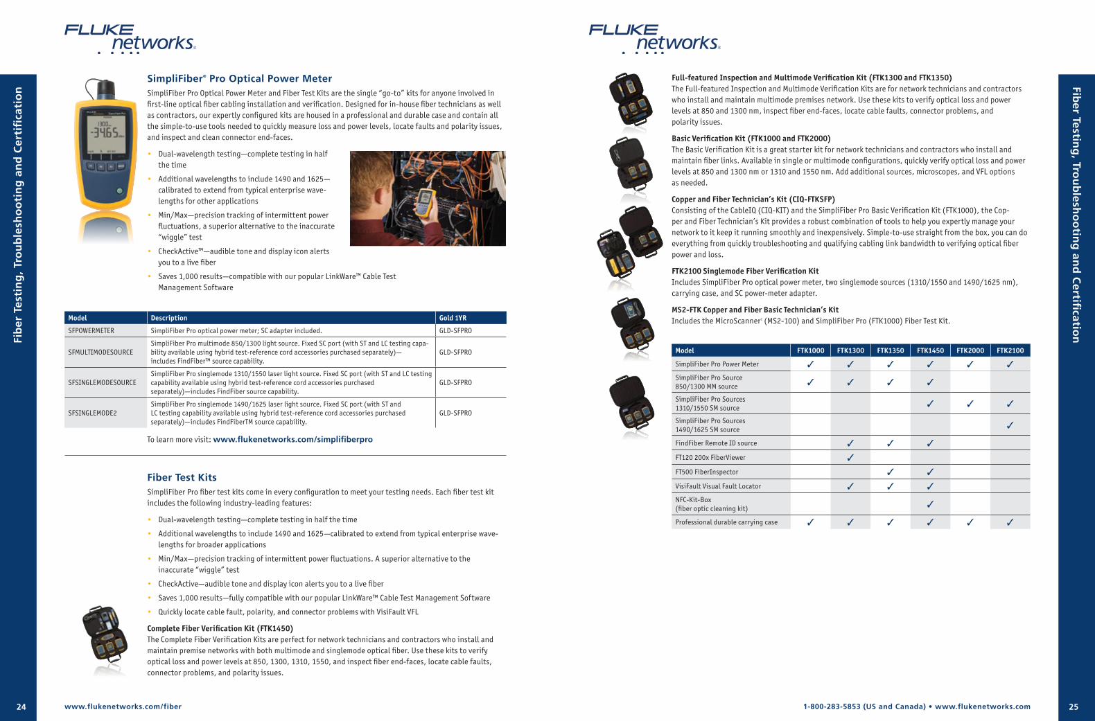
1-800-283-5853 (US and Canada) • www.flukenetworks.com24 25
SimpliFiber® Pro Optical Power Meter SimpliFiber Pro Optical Power Meter and Fiber Test Kits are the single “go-to” kits for anyone involved in first-line optical fiber cabling installation and verification. Designed for in-house fiber technicians as well as contractors, our expertly configured kits are housed in a professional and durable case and contain all the simple-to-use tools needed to quickly measure loss and power levels, locate faults and polarity issues, and inspect and clean connector end-faces.
• Dual-wavelength testing—complete testing in half the time
• Additional wavelengths to include 1490 and 1625—calibrated to extend from typical enterprise wave-lengths for other applications
• Min/Max—precision tracking of intermittent power fluctuations, a superior alternative to the inaccurate “wiggle” test
• CheckActive™—audible tone and display icon alerts you to a live fiber
• Saves 1,000 results—compatible with our popular LinkWare™ Cable Test Management Software
Model Description Gold 1YR
SFPOWERMETER SimpliFiber Pro optical power meter; SC adapter included. GLD-SFPRO
SFMULTIMODESOURCESimpliFiber Pro multimode 850/1300 light source. Fixed SC port (with ST and LC testing capa-bility available using hybrid test-reference cord accessories purchased separately)— includes FindFiber™ source capability.
GLD-SFPRO
SFSINGLEMODESOURCESimpliFiber Pro singlemode 1310/1550 laser light source. Fixed SC port (with ST and LC testing capability available using hybrid test-reference cord accessories purchased separately)—includes FindFiber source capability.
GLD-SFPRO
SFSINGLEMODE2SimpliFiber Pro singlemode 1490/1625 laser light source. Fixed SC port (with ST and LC testing capability available using hybrid test-reference cord accessories purchased separately)—includes FindFiberTM source capability.
GLD-SFPRO
Fiber Test Kits SimpliFiber Pro fiber test kits come in every configuration to meet your testing needs. Each fiber test kit includes the following industry-leading features:
• Dual-wavelength testing—complete testing in half the time
• Additional wavelengths to include 1490 and 1625—calibrated to extend from typical enterprise wave-lengths for broader applications
• Min/Max—precision tracking of intermittent power fluctuations. A superior alternative to the inaccurate “wiggle” test
• CheckActive—audible tone and display icon alerts you to a live fiber
• Saves 1,000 results—fully compatible with our popular LinkWare™ Cable Test Management Software
• Quickly locate cable fault, polarity, and connector problems with VisiFault VFL
Complete Fiber Verification Kit (FTK1450)The Complete Fiber Verification Kits are perfect for network technicians and contractors who install and maintain premise networks with both multimode and singlemode optical fiber. Use these kits to verify optical loss and power levels at 850, 1300, 1310, 1550, and inspect fiber end-faces, locate cable faults, connector problems, and polarity issues.
Full-featured Inspection and Multimode Verification Kit (FTK1300 and FTK1350)The Full-featured Inspection and Multimode Verification Kits are for network technicians and contractors who install and maintain multimode premises network. Use these kits to verify optical loss and power levels at 850 and 1300 nm, inspect fiber end-faces, locate cable faults, connector problems, and polarity issues.
Basic Verification Kit (FTK1000 and FTK2000) The Basic Verification Kit is a great starter kit for network technicians and contractors who install and maintain fiber links. Available in single or multimode configurations, quickly verify optical loss and power levels at 850 and 1300 nm or 1310 and 1550 nm. Add additional sources, microscopes, and VFL options as needed.
Copper and Fiber Technician’s Kit (CIQ-FTKSFP) Consisting of the CableIQ (CIQ-KIT) and the SimpliFiber Pro Basic Verification Kit (FTK1000), the Cop-per and Fiber Technician’s Kit provides a robust combination of tools to help you expertly manage your network to it keep it running smoothly and inexpensively. Simple-to-use straight from the box, you can do everything from quickly troubleshooting and qualifying cabling link bandwidth to verifying optical fiber power and loss.
FTK2100 Singlemode Fiber Verification Kit Includes SimpliFiber Pro optical power meter, two singlemode sources (1310/1550 and 1490/1625 nm), carrying case, and SC power-meter adapter.
MS2-FTK Copper and Fiber Basic Technician’s Kit Includes the MicroScanner2 (MS2-100) and SimpliFiber Pro (FTK1000) Fiber Test Kit.
Model FTK1000 FTK1300 FTK1350 FTK1450 FTK2000 FTK2100
SimpliFiber Pro Power Meter 3 3 3 3 3 3
SimpliFiber Pro Source 850/1300 MM source 3 3 3 3
SimpliFiber Pro Sources 1310/1550 SM source 3 3 3
SimpliFiber Pro Sources 1490/1625 SM source 3
FindFiber Remote ID source 3 3 3
FT120 200x FiberViewer 3
FT500 FiberInspector 3 3
VisiFault Visual Fault Locator 3 3 3
NFC-Kit-Box (fiber optic cleaning kit) 3
Professional durable carrying case 3 3 3 3 3 3
www.flukenetworks.com/fiber
Fib
er T
esti
ng
, Tr
ou
ble
sho
oti
ng
an
d C
erti
fica
tio
nFib
er Testing
, Trou
blesh
oo
ting
and
Certifi
cation
To learn more visit: www.flukenetworks.com/simplifiberpro
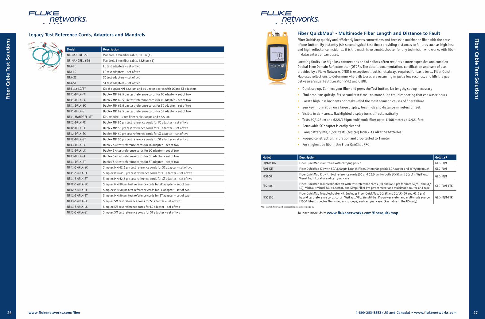
1-800-283-5853 (US and Canada) • www.flukenetworks.com26 27
Legacy Test Reference Cords, Adapters and Mandrels
Model Description
NF-MANDREL-50 Mandrel, 3 mm fiber cable, 50 μm (1)
NF-MANDREL-625 Mandrel, 3 mm fiber cable, 62.5 μm (1)
NFA-FC FC test adapters – set of two
NFA-LC LC test adapters – set of two
NFA-SC SC test adapters – set of two
NFA-ST ST test adapters – set of two
NFB1/2-LC/ST Kit of duplex MM 62.5 μm and 50 μm test cords with LC and ST adapters
NFK1-DPLX-FC Duplex MM 62.5 μm test reference cords for FC adapter – set of two
NFK1-DPLX-LC Duplex MM 62.5 μm test reference cords for LC adapter – set of two
NFK1-DPLX-SC Duplex MM 62.5 μm test reference cords for SC adapter – set of two
NFK1-DPLX-ST Duplex MM 62.5 μm test reference cords for ST adapter – set of two
NFK1-MANDREL-KIT Kit, mandrel, 3 mm fiber cable, 50 μm and 62.5 μm
NFK2-DPLX-FC Duplex MM 50 μm test reference cords for FC adapter – set of two
NFK2-DPLX-LC Duplex MM 50 μm test reference cords for LC adapter – set of two
NFK2-DPLX-SC Duplex MM 50 μm test reference cords for SC adapter – set of two
NFK2-DPLX-ST Duplex MM 50 μm test reference cords for ST adapter – set of two
NFK3-DPLX-FC Duplex SM test reference cords for FC adapter – set of two
NFK3-DPLX-LC Duplex SM test reference cords for LC adapter – set of two
NFK3-DPLX-SC Duplex SM test reference cords for SC adapter – set of two
NFK3-DPLX-ST Duplex SM test reference cords for ST adapter – set of two
NFK1-SMPLX-SC Simplex MM 62.5 µm test reference cords for SC adapter – set of two
NFK1-SMPLX-LC Simplex MM 62.5 µm test reference cords for LC adapter – set of two
NFK1-SMPLX-ST Simplex MM 62.5 µm test reference cords for ST adapter – set of two
NFK2-SMPLX-SC Simplex MM 50 µm test reference cords for SC adapter – set of two
NFK2-SMPLX-LC Simplex MM 50 µm test reference cords for LC adapter – set of two
NFK2-SMPLX-ST Simplex MM 50 µm test reference cords for ST adapter – set of two
NFK3-SMPLX-SC Simplex SM test reference cords for SC adapter – set of two
NFK3-SMPLX-LC Simplex SM test reference cords for LC adapter – set of two
NFK3-SMPLX-ST Simplex SM test reference cords for ST adapter – set of two
Fiber QuickMap™ - Multimode Fiber Length and Distance to FaultFiber QuickMap quickly and efficiently locates connections and breaks in multimode fiber with the press of one-button. By instantly (six second typical test time) providing distances to failures such as high-loss and high-reflectance incidents, it is the must-have troubleshooter for any technician who works with fiber in datacenters or campuses.
Locating faults like high loss connections or bad splices often requires a more expensive and complex Optical Time Domain Reflectometer (OTDR). The detail, documentation, certification and ease of use provided by a Fluke Networks OTDR is exceptional, but is not always required for basic tests. Fiber Quick Map uses reflections to determine where db losses are occurring in just a few seconds, and fills the gap between a Visual Fault Locator (VFL) and OTDR.
• Quick set-up. Connect your fiber and press the Test button. No lengthy set-up necessary
• Find problems quickly. Six-second test time—no more blind troubleshooting that can waste hours
• Locate high loss incidents or breaks—find the most common causes of fiber failure
• See Key information on a large display; loss in db and distance in meters or feet
• Visible in dark areas. Backlighted display turns off automatically
• Tests 50/125µm and 62.5/125µm multimode fiber up to 1,500 meters / 4,921 feet
• Removable SC adapter is easily cleaned
• Long battery life, 1,500 tests (typical) from 2 AA alkaline batteries
• Rugged construction; vibration and drop tested to 1 meter
• For singlemode fiber - Use Fiber OneShot PRO
www.flukenetworks.com/fiber
Model Description Gold 1YR
FQM-MAIN Fiber QuickMap mainframe with carrying pouch GLD-FQM
FQM-KIT Fiber QuickMap Kit with SC/LC 50 μm Launch Fiber, Interchangeable LC Adapter and carrying pouch GLD-FQM
FTS900Fiber QuickMap Kit with test reference cords (50 and 62.5 µm for both SC/SC and SC/LC), VisiFault Visual Fault Locator and carrying case
GLD-FQM
FTS1000Fiber QuickMap Troubleshooter Kit with test reference cords (50 and 62.5 µm for both SC/SC and SC/LC), VisiFault Visual Fault Locator, and SimpliFiber Pro power meter and multimode source and case
GLD-FQM-FTK
FTS1100Fiber QuickMap Troubleshooter Kit: Includes Fiber QuickMap, SC/SC and SC/LC (50 and 62.5 μm) hybrid test reference cords cords, VisiFault VFL, SimpliFiber Pro power meter and multimode source, FT500 FiberInspector Mini video microscope, and carrying case. (Available in the US only)
GLD-FQM-FTK
*For launch fibers and accessories please see page 19
Fib
er C
able
Tes
t So
luti
on
s Fiber C
able Test So
lutio
ns
To learn more visit: www.flukenetworks.com/fiberquickmap
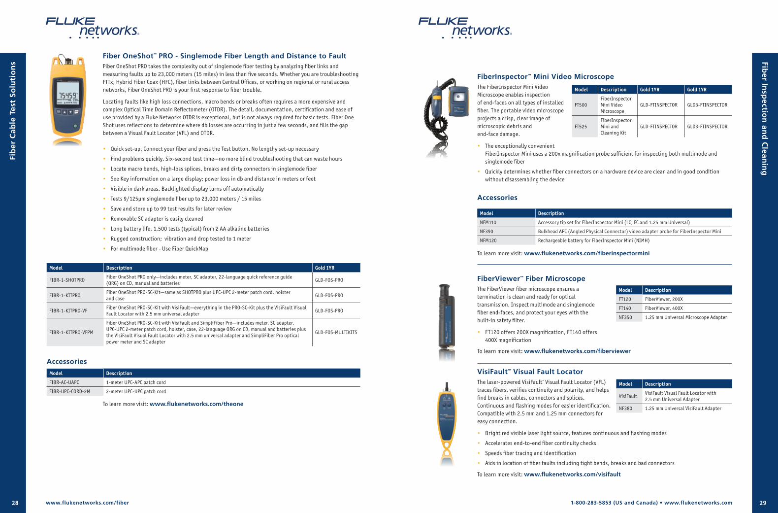
1-800-283-5853 (US and Canada) • www.flukenetworks.com28 29
FiberInspector™ Mini Video MicroscopeThe FiberInspector Mini Video Microscope enables inspection of end-faces on all types of installed fiber. The portable video microscope projects a crisp, clear image of microscopic debris and end-face damage.
• The exceptionally convenient FiberInspector Mini uses a 200x magnification probe sufficient for inspecting both multimode and singlemode fiber
• Quickly determines whether fiber connectors on a hardware device are clean and in good condition without disassembling the device
Accessories
Model Description
NFM110 Accessory tip set for FiberInspector Mini (LC, FC and 1.25 mm Universal)
NF390 Bulkhead APC (Angled Physical Connector) video adapter probe for FiberInspector Mini
NFM120 Rechargeable battery for FiberInspector Mini (NIMH)
To learn more visit: www.flukenetworks.com/fiberinspectormini
Fiber OneShot™ PRO - Singlemode Fiber Length and Distance to FaultFiber OneShot PRO takes the complexity out of singlemode fiber testing by analyzing fiber links and measuring faults up to 23,000 meters (15 miles) in less than five seconds. Whether you are troubleshooting FTTx, Hybrid Fiber Coax (HFC), fiber links between Central Offices, or working on regional or rural access networks, Fiber OneShot PRO is your first response to fiber trouble.
Locating faults like high loss connections, macro bends or breaks often requires a more expensive and complex Optical Time Domain Reflectometer (OTDR). The detail, documentation, certification and ease of use provided by a Fluke Networks OTDR is exceptional, but is not always required for basic tests. Fiber One Shot uses reflections to determine where db losses are occurring in just a few seconds, and fills the gap between a Visual Fault Locator (VFL) and OTDR.
• Quick set-up. Connect your fiber and press the Test button. No lengthy set-up necessary
• Find problems quickly. Six-second test time—no more blind troubleshooting that can waste hours
• Locate macro bends, high-loss splices, breaks and dirty connectors in singlemode fiber
• See Key information on a large display; power loss in db and distance in meters or feet
• Visible in dark areas. Backlighted display turns off automatically
• Tests 9/125µm singlemode fiber up to 23,000 meters / 15 miles
• Save and store up to 99 test results for later review
• Removable SC adapter is easily cleaned
• Long battery life, 1,500 tests (typical) from 2 AA alkaline batteries
• Rugged construction; vibration and drop tested to 1 meter
• For multimode fiber - Use Fiber QuickMap
Model Description Gold 1YR
FIBR-1-SHOTPRO Fiber OneShot PRO only—includes meter, SC adapter, 22-language quick reference guide (QRG) on CD, manual and batteries
GLD-FOS-PRO
FIBR-1-KITPROFiber OneShot PRO-SC-Kit—same as SHOTPRO plus UPC-UPC 2-meter patch cord, holster and case
GLD-FOS-PRO
FIBR-1-KITPRO-VFFiber OneShot PRO-SC-Kit with VisiFault—everything in the PRO-SC-Kit plus the VisiFault Visual Fault Locator with 2.5 mm universal adapter
GLD-FOS-PRO
FIBR-1-KITPRO-VFPM
Fiber OneShot PRO-SC-Kit with VisiFault and SimpliFiber Pro—includes meter, SC adapter, UPC-UPC 2-meter patch cord, holster, case, 22-language QRG on CD, manual and batteries plus the VisiFault Visual Fault Locator with 2.5 mm universal adapter and SimpliFiber Pro optical power meter and SC adapter
GLD-FOS-MULTIKITS
Accessories
Model Description
FIBR-AC-UAPC 1-meter UPC-APC patch cord
FIBR-UPC-CORD-2M 2-meter UPC-UPC patch cord
Model Description
FT120 FiberViewer, 200X
FT140 FiberViewer, 400X
NF350 1.25 mm Universal Microscope Adapter
Model Description Gold 1YR Gold 1YR
FT500FiberInspector Mini Video Microscope
GLD-FTINSPECTOR GLD3-FTINSPECTOR
FT525FiberInspector Mini and Cleaning Kit
GLD-FTINSPECTOR GLD3-FTINSPECTOR
Model Description
VisiFaultVisiFault Visual Fault Locator with 2.5 mm Universal Adapter
NF380 1.25 mm Universal VisiFault Adapter
FiberViewer™ Fiber MicroscopeThe FiberViewer fiber microscope ensures a termination is clean and ready for optical transmission. Inspect multimode and singlemode fiber end-faces, and protect your eyes with the built-in safety filter.
• FT120 offers 200X magnification, FT140 offers 400X magnification
To learn more visit: www.flukenetworks.com/fiberviewer
VisiFault™ Visual Fault LocatorThe laser-powered VisiFault™ Visual Fault Locator (VFL) traces fibers, verifies continuity and polarity, and helps find breaks in cables, connectors and splices. Continuous and flashing modes for easier identification. Compatible with 2.5 mm and 1.25 mm connectors for easy connection.
• Bright red visible laser light source, features continuous and flashing modes
• Accelerates end-to-end fiber continuity checks
• Speeds fiber tracing and identification
• Aids in location of fiber faults including tight bends, breaks and bad connectors
To learn more visit: www.flukenetworks.com/visifault
Fib
er C
able
Tes
t So
luti
on
s Fiber In
spectio
n an
d C
leanin
g
www.flukenetworks.com/fiber
To learn more visit: www.flukenetworks.com/theone
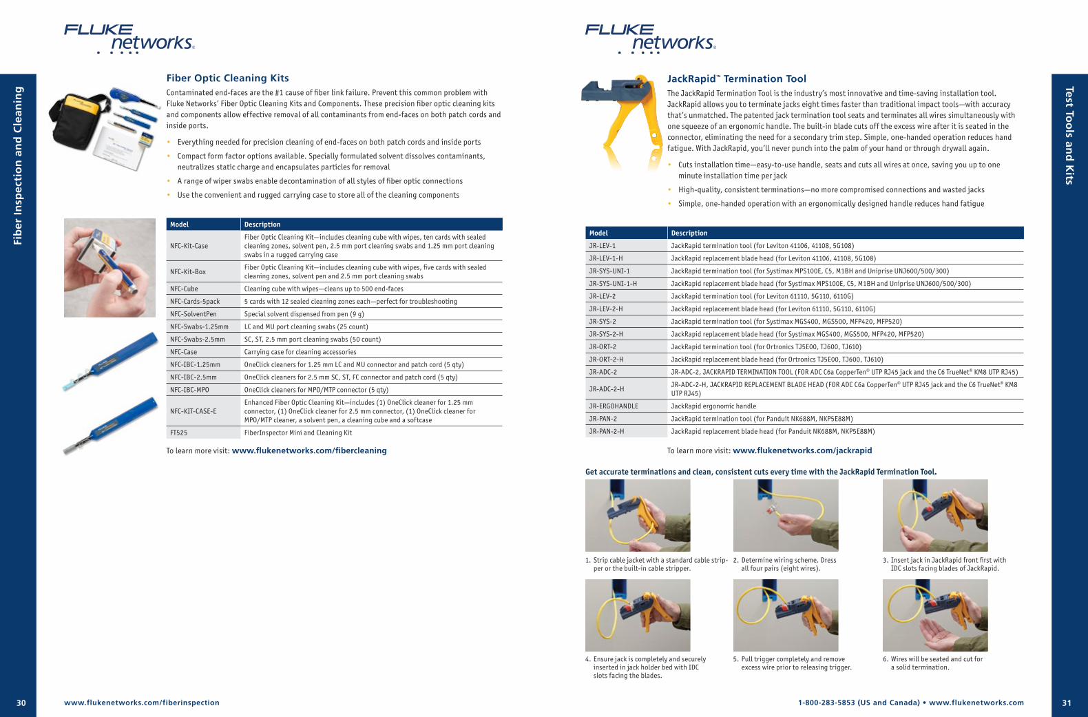
1-800-283-5853 (US and Canada) • www.flukenetworks.com30 31
Fiber Optic Cleaning KitsContaminated end-faces are the #1 cause of fiber link failure. Prevent this common problem with Fluke Networks’ Fiber Optic Cleaning Kits and Components. These precision fiber optic cleaning kits and components allow effective removal of all contaminants from end-faces on both patch cords and inside ports.
• Everything needed for precision cleaning of end-faces on both patch cords and inside ports
• Compact form factor options available. Specially formulated solvent dissolves contaminants, neutralizes static charge and encapsulates particles for removal
• A range of wiper swabs enable decontamination of all styles of fiber optic connections
• Use the convenient and rugged carrying case to store all of the cleaning components
Model Description
NFC-Kit-CaseFiber Optic Cleaning Kit—includes cleaning cube with wipes, ten cards with sealed cleaning zones, solvent pen, 2.5 mm port cleaning swabs and 1.25 mm port cleaning swabs in a rugged carrying case
NFC-Kit-BoxFiber Optic Cleaning Kit—includes cleaning cube with wipes, five cards with sealed cleaning zones, solvent pen and 2.5 mm port cleaning swabs
NFC-Cube Cleaning cube with wipes—cleans up to 500 end-faces
NFC-Cards-5pack 5 cards with 12 sealed cleaning zones each—perfect for troubleshooting
NFC-SolventPen Special solvent dispensed from pen (9 g)
NFC-Swabs-1.25mm LC and MU port cleaning swabs (25 count)
NFC-Swabs-2.5mm SC, ST, 2.5 mm port cleaning swabs (50 count)
NFC-Case Carrying case for cleaning accessories
NFC-IBC-1.25mm OneClick cleaners for 1.25 mm LC and MU connector and patch cord (5 qty)
NFC-IBC-2.5mm OneClick cleaners for 2.5 mm SC, ST, FC connector and patch cord (5 qty)
NFC-IBC-MPO OneClick cleaners for MPO/MTP connector (5 qty)
NFC-KIT-CASE-EEnhanced Fiber Optic Cleaning Kit—includes (1) OneClick cleaner for 1.25 mm connector, (1) OneClick cleaner for 2.5 mm connector, (1) OneClick cleaner for MPO/MTP cleaner, a solvent pen, a cleaning cube and a softcase
FT525 FiberInspector Mini and Cleaning Kit
To learn more visit: www.flukenetworks.com/fibercleaning
www.flukenetworks.com/fiberinspection
Fib
er I
nsp
ecti
on
an
d C
lean
ing
JackRapid™ Termination ToolThe JackRapid Termination Tool is the industry’s most innovative and time-saving installation tool. JackRapid allows you to terminate jacks eight times faster than traditional impact tools—with accuracy that’s unmatched. The patented jack termination tool seats and terminates all wires simultaneously with one squeeze of an ergonomic handle. The built-in blade cuts off the excess wire after it is seated in the connector, eliminating the need for a secondary trim step. Simple, one-handed operation reduces hand fatigue. With JackRapid, you’ll never punch into the palm of your hand or through drywall again.
• Cuts installation time—easy-to-use handle, seats and cuts all wires at once, saving you up to one minute installation time per jack
• High-quality, consistent terminations—no more compromised connections and wasted jacks
• Simple, one-handed operation with an ergonomically designed handle reduces hand fatigue
Model Description
JR-LEV-1 JackRapid termination tool (for Leviton 41106, 41108, 5G108)
JR-LEV-1-H JackRapid replacement blade head (for Leviton 41106, 41108, 5G108)
JR-SYS-UNI-1 JackRapid termination tool (for Systimax MPS100E, C5, M1BH and Uniprise UNJ600/500/300)
JR-SYS-UNI-1-H JackRapid replacement blade head (for Systimax MPS100E, C5, M1BH and Uniprise UNJ600/500/300)
JR-LEV-2 JackRapid termination tool (for Leviton 61110, 5G110, 6110G)
JR-LEV-2-H JackRapid replacement blade head (for Leviton 61110, 5G110, 6110G)
JR-SYS-2 JackRapid termination tool (for Systimax MGS400, MGS500, MFP420, MFP520)
JR-SYS-2-H JackRapid replacement blade head (for Systimax MGS400, MGS500, MFP420, MFP520)
JR-ORT-2 JackRapid termination tool (for Ortronics TJ5E00, TJ600, TJ610)
JR-ORT-2-H JackRapid replacement blade head (for Ortronics TJ5E00, TJ600, TJ610)
JR-ADC-2 JR-ADC-2, JACKRAPID TERMINATION TOOL (FOR ADC C6a CopperTen® UTP RJ45 jack and the C6 TrueNet® KM8 UTP RJ45)
JR-ADC-2-HJR-ADC-2-H, JACKRAPID REPLACEMENT BLADE HEAD (FOR ADC C6a CopperTen® UTP RJ45 jack and the C6 TrueNet® KM8 UTP RJ45)
JR-ERGOHANDLE JackRapid ergonomic handle
JR-PAN-2 JackRapid termination tool (for Panduit NK688M, NKP5E88M)
JR-PAN-2-H JackRapid replacement blade head (for Panduit NK688M, NKP5E88M)
6. Wires will be seated and cut for a solid termination.
1. Strip cable jacket with a standard cable strip-per or the built-in cable stripper.
2. Determine wiring scheme. Dress all four pairs (eight wires).
3. Insert jack in JackRapid front first with IDC slots facing blades of JackRapid.
4. Ensure jack is completely and securely inserted in jack holder bed with IDC slots facing the blades.
5. Pull trigger completely and remove excess wire prior to releasing trigger.
Test Too
ls and
Kits
Get accurate terminations and clean, consistent cuts every time with the JackRapid Termination Tool.
To learn more visit: www.flukenetworks.com/jackrapid
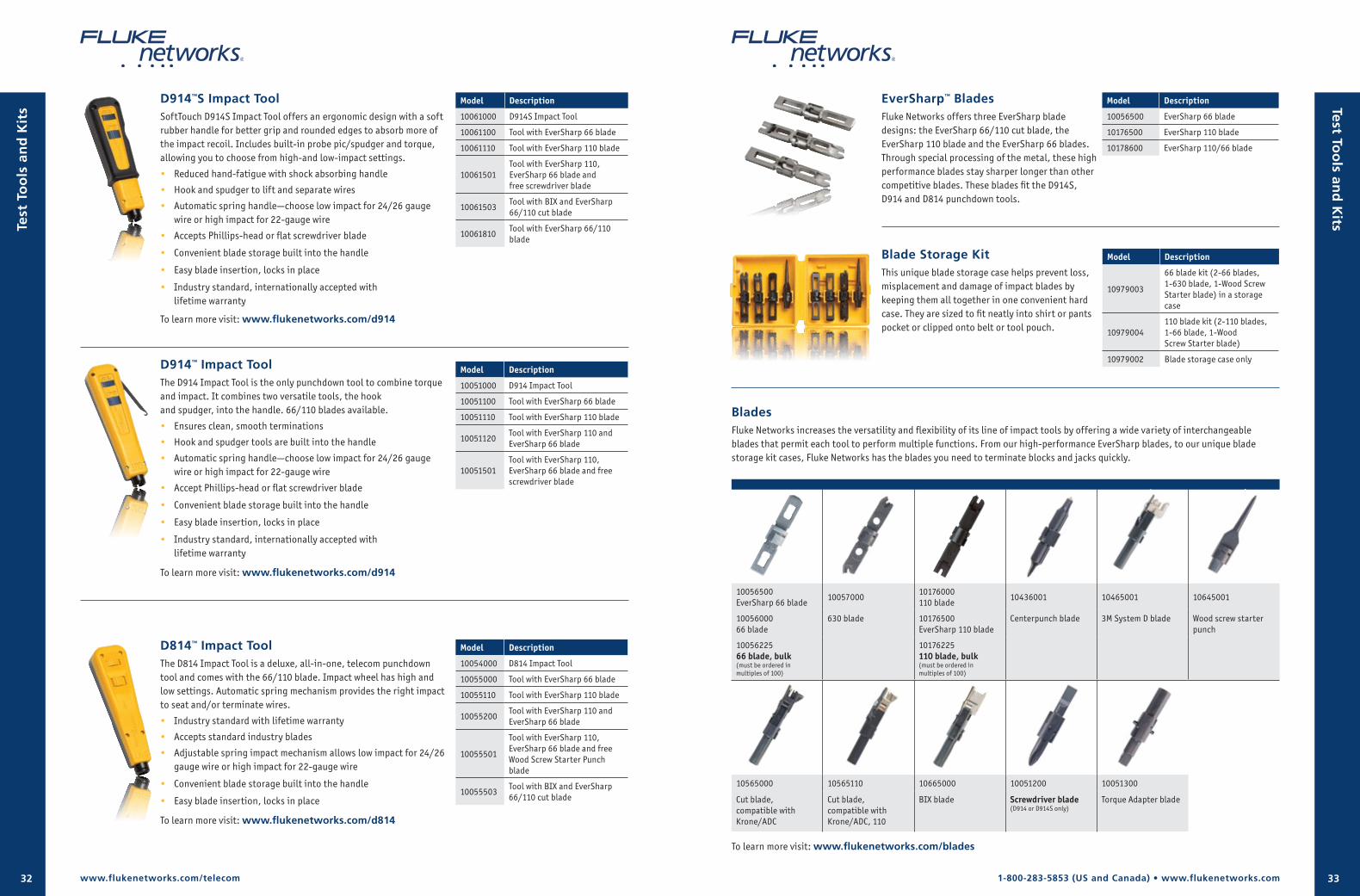
1-800-283-5853 (US and Canada) • www.flukenetworks.com32 33
D914™ Impact ToolThe D914 Impact Tool is the only punchdown tool to combine torque and impact. It combines two versatile tools, the hook and spudger, into the handle. 66/110 blades available.
• Ensures clean, smooth terminations
• Hook and spudger tools are built into the handle
• Automatic spring handle—choose low impact for 24/26 gauge wire or high impact for 22-gauge wire
• Accept Phillips-head or flat screwdriver blade
• Convenient blade storage built into the handle
• Easy blade insertion, locks in place
• Industry standard, internationally accepted with lifetime warranty
To learn more visit: www.flukenetworks.com/d914
D814™ Impact ToolThe D814 Impact Tool is a deluxe, all-in-one, telecom punchdown tool and comes with the 66/110 blade. Impact wheel has high and low settings. Automatic spring mechanism provides the right impact to seat and/or terminate wires.
• Industry standard with lifetime warranty
• Accepts standard industry blades
• Adjustable spring impact mechanism allows low impact for 24/26 gauge wire or high impact for 22-gauge wire
• Convenient blade storage built into the handle
• Easy blade insertion, locks in place
To learn more visit: www.flukenetworks.com/d814
D914™S Impact ToolSoftTouch D914S Impact Tool offers an ergonomic design with a soft rubber handle for better grip and rounded edges to absorb more of the impact recoil. Includes built-in probe pic/spudger and torque, allowing you to choose from high-and low-impact settings.
• Reduced hand-fatigue with shock absorbing handle
• Hook and spudger to lift and separate wires
• Automatic spring handle—choose low impact for 24/26 gauge wire or high impact for 22-gauge wire
• Accepts Phillips-head or flat screwdriver blade
• Convenient blade storage built into the handle
• Easy blade insertion, locks in place
• Industry standard, internationally accepted with lifetime warranty
To learn more visit: www.flukenetworks.com/d914
Model Description
10051000 D914 Impact Tool
10051100 Tool with EverSharp 66 blade
10051110 Tool with EverSharp 110 blade
10051120Tool with EverSharp 110 and EverSharp 66 blade
10051501Tool with EverSharp 110, EverSharp 66 blade and free screwdriver blade
Model Description
10061000 D914S Impact Tool
10061100 Tool with EverSharp 66 blade
10061110 Tool with EverSharp 110 blade
10061501Tool with EverSharp 110, EverSharp 66 blade and free screwdriver blade
10061503Tool with BIX and EverSharp 66/110 cut blade
10061810Tool with EverSharp 66/110 blade
Model Description
10054000 D814 Impact Tool
10055000 Tool with EverSharp 66 blade
10055110 Tool with EverSharp 110 blade
10055200Tool with EverSharp 110 and EverSharp 66 blade
10055501
Tool with EverSharp 110, EverSharp 66 blade and free Wood Screw Starter Punch blade
10055503Tool with BIX and EverSharp 66/110 cut blade
www.flukenetworks.com/telecom
Test
To
ols
an
d K
its Test To
ols an
d K
its
BladesFluke Networks increases the versatility and flexibility of its line of impact tools by offering a wide variety of interchangeable blades that permit each tool to perform multiple functions. From our high-performance EverSharp blades, to our unique blade storage kit cases, Fluke Networks has the blades you need to terminate blocks and jacks quickly.
10056500EverSharp 66 blade
1005700010176000110 blade
10436001 10465001 10645001
1005600066 blade
630 blade 10176500EverSharp 110 blade
Centerpunch blade 3M System D blade Wood screw starter punch
1005622566 blade, bulk (must be ordered in multiples of 100)
10176225 110 blade, bulk (must be ordered in multiples of 100)
10565000 10565110 10665000 10051200 10051300
Cut blade, compatible with Krone/ADC
Cut blade, compatible with Krone/ADC, 110
BIX blade Screwdriver blade (D914 or D914S only)
Torque Adapter blade
To learn more visit: www.flukenetworks.com/blades
EverSharp™ BladesFluke Networks offers three EverSharp blade designs: the EverSharp 66/110 cut blade, the EverSharp 110 blade and the EverSharp 66 blades. Through special processing of the metal, these high performance blades stay sharper longer than other competitive blades. These blades fit the D914S, D914 and D814 punchdown tools.
Blade Storage Kit This unique blade storage case helps prevent loss, misplacement and damage of impact blades by keeping them all together in one convenient hard case. They are sized to fit neatly into shirt or pants pocket or clipped onto belt or tool pouch.
Model Description
10056500 EverSharp 66 blade
10176500 EverSharp 110 blade
10178600 EverSharp 110/66 blade
Model Description
10979003
66 blade kit (2-66 blades, 1-630 blade, 1-Wood Screw Starter blade) in a storage case
10979004110 blade kit (2-110 blades, 1-66 blade, 1-Wood Screw Starter blade)
10979002 Blade storage case only
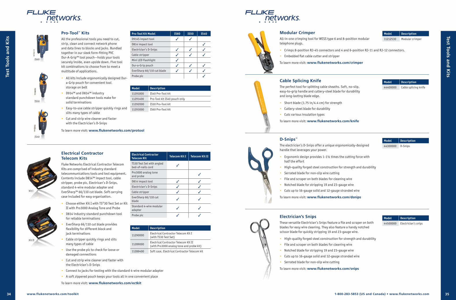
1-800-283-5853 (US and Canada) • www.flukenetworks.com34 35
Electrical Contractor Telecom KitsFluke Networks Electrical Contractor Telecom Kits are comprised of industry standard telecommunications tools and test equipment. Contents include D814™ impact tool, cable stripper, probe pic, Electrican’s D-Snips, standard 4-wire modular adapter and EverSharp™ 66/110 cut blade. Soft carrying case included for easy organization.
• Choose either Kit I with TS®30 Test Set or Kit II with Pro3000 Analog Tone and Probe
• D814 industry standard punchdown tool for reliable terminations
• EverSharp 66/110 cut blade provides flexibility for different block and jack terminations
• Cable stripper quickly rings and slits many types of cable
• Use the probe pic to check for loose or damaged connections
• Cut and strip wire cleaner and faster with the Electrician’s D-Snips
• Connect to jacks for testing with the standard 4-wire modular adapter
• A soft zippered pouch keeps your tools all in one convenient place
To learn more visit: www.flukenetworks.com/ectkit
Pro-Tool™ KitsAll the professional tools you need to cut, strip, clean and connect network phone and data lines to blocks and jacks. Bundled together in our sleek form-fitting PVC Dur-A-Grip™ tool pouch—holds your tools securely inside, even upside down. Five tool kit combinations to choose from to meet a multitude of applications.
• All kits include ergonomically designed Dur-a-Grip pouch for convenient tool storage on belt
• D914™ and D814™ industry standard punchdown tools make for solid terminations
• Easy-to-use cable stripper quickly rings and slits many types of cable
• Cut and strip wire cleaner and faster with the Electrician’s D-Snips
To learn more visit: www.flukenetworks.com/protool
Model Description
11291000 IS40 Pro-Tool kit
11291400 Pro-Tool kit IS40 pouch only
11292000 IS50 Pro-Tool kit
11293000 IS60 Pro-Tool kit
Pro-Tool Kit Model IS60 IS50 IS40
D914S impact tool 3 3
D814 impact tool 3
Electrician’s D-Snips 3 3 3
Cable stripper 3 3 3
Mini LED Flashlight 3
Dur-a-Grip pouch 3 3 3
EverSharp 66/110 cut blade 3 3 3
Probe pic 3
Electrical Contractor Telecom Kit Telecom Kit I Telecom Kit II
TS30 Test Set with angled bed-of-nails cord 3
Pro3000 analog tone and probe 3
D814 impact tool 3 3
Electrician’s D-Snips 3 3
Cable stripper 3 3
EverSharp 66/110 cut blade 3 3
Standard 4-wire modular adapter 3 3
Probe pic 3 3
Model Description
11290000Electrical Contractor Telecom Kit I (with TS30 Test Set)
11289000Electrical Contractor Telecom Kit II (with Pro3000 analog tone and probe kit)
11289400 Soft case, Electrical Contractor Telecom kit
IS60
IS50
IS40
Kit I
Kit II
www.flukenetworks.com/toolkit
Test
To
ols
an
d K
its Test To
ols an
d K
its
D-Snips™
The electrician’s D-Snips offer a unique ergonomically-designed handle that leverages your power.
• Ergonomic design provides 1-1½ times the cutting force with half the effort
• High-quality forged steel construction for strength and durability
• Serrated blade for non-slip wire cutting
• File and scraper on both blades for cleaning wire
• Notched blade for stripping 19 and 23-gauge wire
• Cuts up to 16-gauge solid and 12-gauge stranded wire
To learn more visit: www.flukenetworks.com/dsnips
Modular CrimperAll-in-one crimping tool for WESS type 6 and 8-position modular telephone plugs.
• Crimps 8-position RJ-45 connectors and 4 and 6-position RJ-11 and RJ-12 connectors.
• Embedded flat cable cutter and stripper
To learn more visit: www.flukenetworks.com/crimper
Cable Splicing KnifeThe perfect tool for splitting cable sheaths. Soft, no-slip, easy-to-grip handle and cutlery-steel blade for durability and long-lasting blade edge.
• Short blade (1.75 in/4.4 cm) for strength
• Cutlery-steel blade for durability
• Cuts various insulation types
To learn more visit: www.flukenetworks.com/knife
Electrician’s SnipsThese versatile Electrician’s Snips feature a file and scraper on both blades for easy wire cleaning. They also feature a handy notched scissor blade for quickly stripping 19 and 23-gauge wire.
• High-quality forged steel construction for strength and durability
• File and scraper on both blades for cleaning wire
• Notched blade for stripping 19 and 23-gauge wire
• Cuts up to 16-gauge solid and 12-gauge stranded wire
• Serrated blade for non-slip wire cutting
To learn more visit: www.flukenetworks.com/snips
Model Description
44400000 Cable splicing knife
Model Description
44300000 D-Snips
Model Description
11212530 Modular crimper
Model Description
44500000 Electrician’s snips
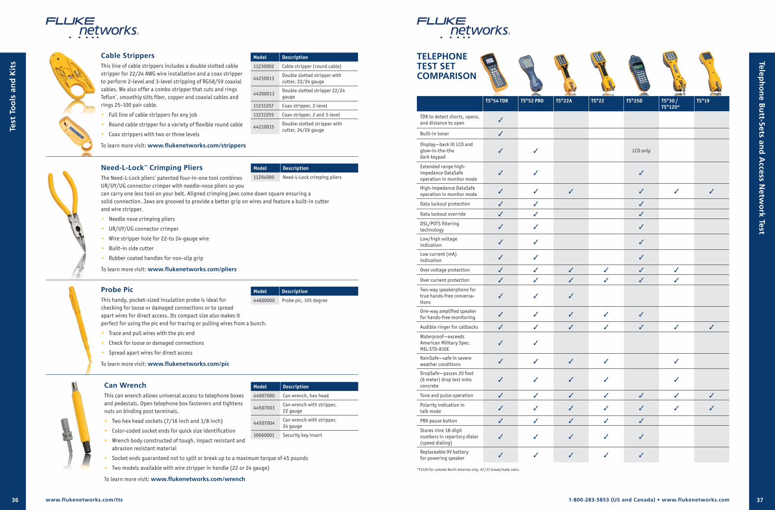
1-800-283-5853 (US and Canada) • www.flukenetworks.com36 37
Cable StrippersThis line of cable strippers includes a double slotted cable stripper for 22/24 AWG wire installation and a coax stripper to perform 2-level and 3-level stripping of RG58/59 coaxial cables. We also offer a combo stripper that cuts and rings Teflon®, smoothly slits fiber, copper and coaxial cables and rings 25-100 pair cable.
• Full line of cable strippers for any job
• Round cable stripper for a variety of flexible round cable
• Coax strippers with two or three levels
To learn more visit: www.flukenetworks.com/strippers
Need-L-Lock™ Crimping PliersThe Need-L-Lock pliers’ patented four-in-one tool combines UR/UY/UG connector crimper with needle-nose pliers so you can carry one less tool on your belt. Aligned crimping jaws come down square ensuring a solid connection. Jaws are grooved to provide a better grip on wires and feature a built-in cutter and wire stripper.
• Needle nose crimping pliers
• UR/UY/UG connector crimper
• Wire stripper hole for 22-to 24-gauge wire
• Built-in side cutter
• Rubber coated handles for non-slip grip
To learn more visit: www.flukenetworks.com/pliers
Probe PicThis handy, pocket-sized insulation probe is ideal for checking for loose or damaged connections or to spread apart wires for direct access. Its compact size also makes it perfect for using the pic end for tracing or pulling wires from a bunch.
• Trace and pull wires with the pic end
• Check for loose or damaged connections
• Spread apart wires for direct access
To learn more visit: www.flukenetworks.com/pic
Can WrenchThis can wrench allows universal access to telephone boxes and pedestals. Open telephone box fasteners and tightens nuts on binding post terminals.
• Two hex head sockets (7/16 inch and 3/8 inch)
• Color-coded socket ends for quick size identification
• Wrench body constructed of tough, impact resistant and abrasion resistant material
• Socket ends guaranteed not to split or break up to a maximum torque of 45 pounds
• Two models available with wire stripper in handle (22 or 24 gauge)
To learn more visit: www.flukenetworks.com/wrench
Model Description
11230002 Cable stripper (round cable)
44210013Double slotted stripper with cutter, 22/24 gauge
44200013Double slotted stripper 22/24 gauge
11231257 Coax stripper, 2-level
11231255 Coax stripper, 2 and 3-level
44210015Double-slotted stripper with cutter, 24/26 gauge
Model Description
11294000 Need-L-Lock crimping pliers
Model Description
44600000 Probe pic, 105 degree
Model Description
44007000 Can wrench, hex head
44507003Can wrench with stripper, 22 gauge
44507004Can wrench with stripper, 24 gauge
10660001 Security key insert
www.flukenetworks.com/tts
Test
To
ols
an
d K
its
TELEPHONE TEST SET COMPARISON
TS®54 TDR TS®52 PRO TS®22A TS®22 TS®25D TS®30 / TS®120*
TS®19
TDR to detect shorts, opens, and distance to open 3
Built-in toner 3
Display—back lit LCD and glow-in-the-the dark keypad
3 3 LCD only
Extended range high- impedance DataSafe operation in monitor mode
3 3 3
High-impedance DataSafe operation in monitor mode 3 3 3 3 3 3
Data lockout protection 3 3 3
Data lockout override 3 3 3
DSL/POTS filtering technology 3 3 3
Low/high voltage indication 3 3 3
Low current (mA) indication 3 3 3
Over voltage protection 3 3 3 3 3 3
Over current protection 3 3 3 3 3 3
Two-way speakerphone for true hands-free conversa-tions
3 3 3
One-way amplified speaker for hands-free monitoring 3 3 3 3 3
Audible ringer for callbacks 3 3 3 3 3 3 3
Waterproof—exceeds American Military Spec. MIL-STD-810E
3 3
RainSafe—safe in severe weather conditions 3 3 3 3 3
DropSafe—passes 20 foot (6 meter) drop test onto concrete
3 3 3 3 3
Tone and pulse operation 3 3 3 3 3 3 3
Polarity indication in talk mode 3 3 3 3 3 3 3
PBX pause button 3 3 3 3 3
Stores nine 18-digit numbers in repertory dialer (speed dialing)
3 3 3 3 3
Replaceable 9V battery for powering speaker 3 3 3 3 3
*TS120 for outside North America only. 67/33 break/make ratio.
Teleph
on
e Bu
tt-Sets and
Access N
etwo
rk Test
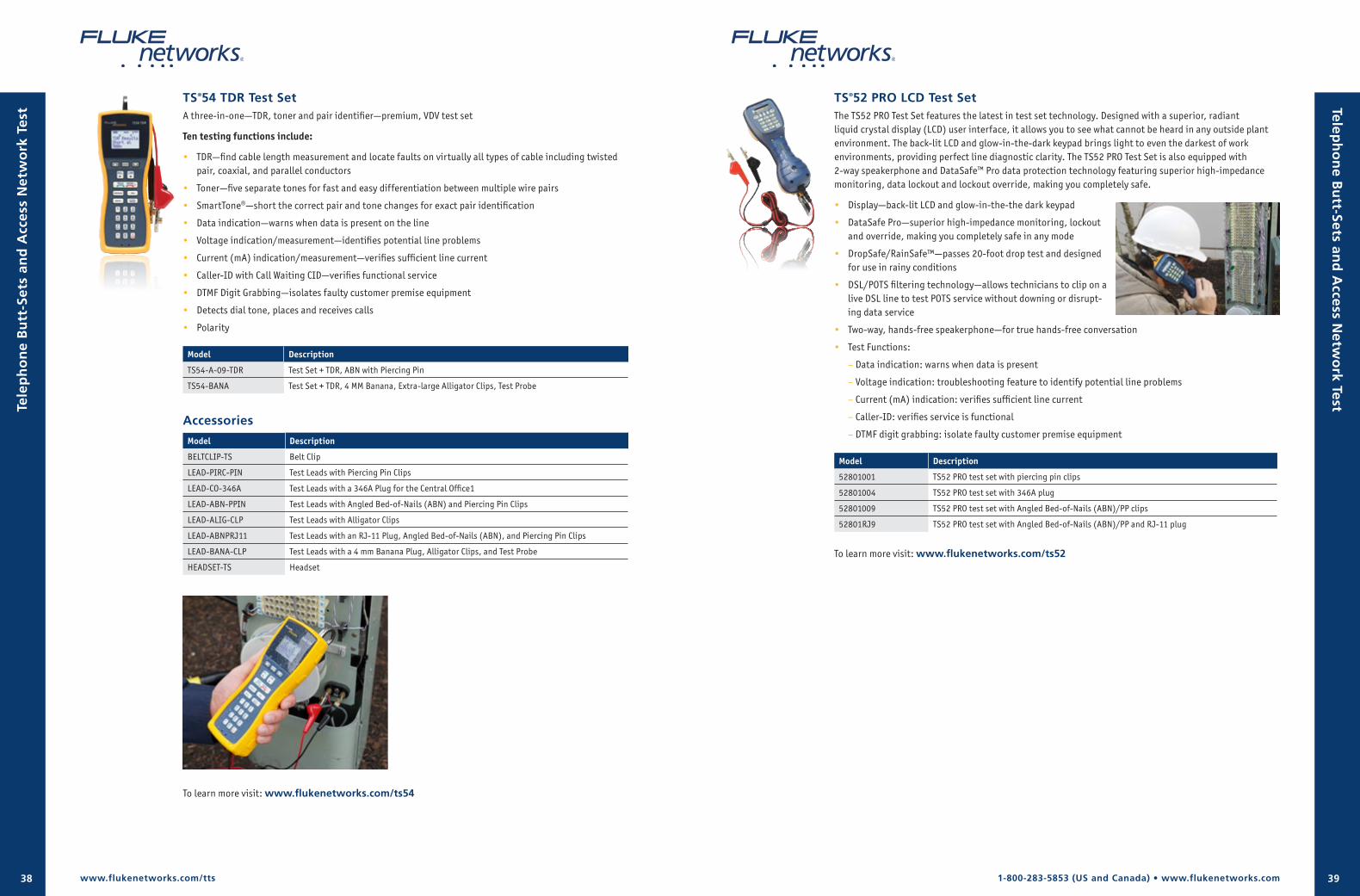
1-800-283-5853 (US and Canada) • www.flukenetworks.com38 39
TS®52 PRO LCD Test SetThe TS52 PRO Test Set features the latest in test set technology. Designed with a superior, radiant liquid crystal display (LCD) user interface, it allows you to see what cannot be heard in any outside plant environment. The back-lit LCD and glow-in-the-dark keypad brings light to even the darkest of work environments, providing perfect line diagnostic clarity. The TS52 PRO Test Set is also equipped with 2-way speakerphone and DataSafe™ Pro data protection technology featuring superior high-impedance monitoring, data lockout and lockout override, making you completely safe.
• Display—back-lit LCD and glow-in-the-the dark keypad
• DataSafe Pro—superior high-impedance monitoring, lockout and override, making you completely safe in any mode
• DropSafe/RainSafe™—passes 20-foot drop test and designed for use in rainy conditions
• DSL/POTS filtering technology—allows technicians to clip on a live DSL line to test POTS service without downing or disrupt-ing data service
• Two-way, hands-free speakerphone—for true hands-free conversation
• Test Functions:
– Data indication: warns when data is present
– Voltage indication: troubleshooting feature to identify potential line problems
– Current (mA) indication: verifies sufficient line current
– Caller-ID: verifies service is functional
– DTMF digit grabbing: isolate faulty customer premise equipment
Model Description
52801001 TS52 PRO test set with piercing pin clips
52801004 TS52 PRO test set with 346A plug
52801009 TS52 PRO test set with Angled Bed-of-Nails (ABN)/PP clips
52801RJ9 TS52 PRO test set with Angled Bed-of-Nails (ABN)/PP and RJ-11 plug
To learn more visit: www.flukenetworks.com/ts52
www.flukenetworks.com/tts
Tele
ph
on
e B
utt
-Set
s an
d A
cces
s N
etw
ork
Tes
t
TS®54 TDR Test SetA three-in-one—TDR, toner and pair identifier—premium, VDV test set
Ten testing functions include:
• TDR—find cable length measurement and locate faults on virtually all types of cable including twisted pair, coaxial, and parallel conductors
• Toner—five separate tones for fast and easy differentiation between multiple wire pairs
• SmartTone®—short the correct pair and tone changes for exact pair identification
• Data indication—warns when data is present on the line
• Voltage indication/measurement—identifies potential line problems
• Current (mA) indication/measurement—verifies sufficient line current
• Caller-ID with Call Waiting CID—verifies functional service
• DTMF Digit Grabbing—isolates faulty customer premise equipment
• Detects dial tone, places and receives calls
• Polarity
Model Description
TS54-A-09-TDR Test Set + TDR, ABN with Piercing Pin
TS54-BANA Test Set + TDR, 4 MM Banana, Extra-large Alligator Clips, Test Probe
Accessories
Model Description
BELTCLIP-TS Belt Clip
LEAD-PIRC-PIN Test Leads with Piercing Pin Clips
LEAD-CO-346A Test Leads with a 346A Plug for the Central Office1
LEAD-ABN-PPIN Test Leads with Angled Bed-of-Nails (ABN) and Piercing Pin Clips
LEAD-ALIG-CLP Test Leads with Alligator Clips
LEAD-ABNPRJ11 Test Leads with an RJ-11 Plug, Angled Bed-of-Nails (ABN), and Piercing Pin Clips
LEAD-BANA-CLP Test Leads with a 4 mm Banana Plug, Alligator Clips, and Test Probe
HEADSET-TS Headset
Teleph
on
e Bu
tt-Sets and
Access N
etwo
rk Test
To learn more visit: www.flukenetworks.com/ts54
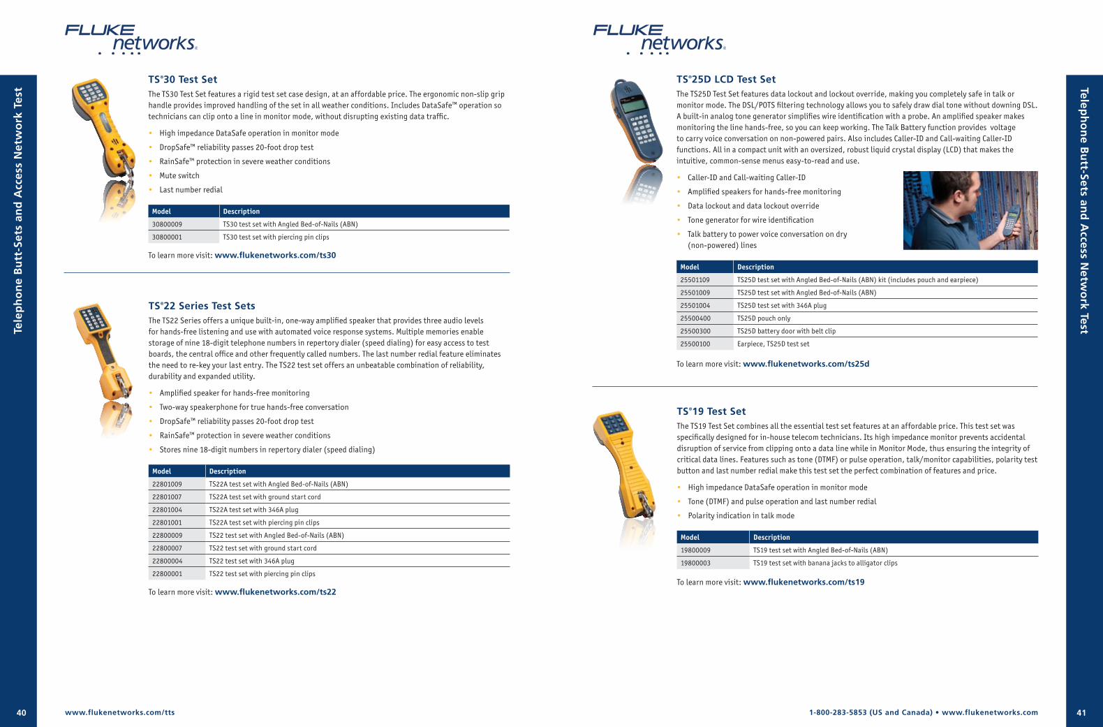
1-800-283-5853 (US and Canada) • www.flukenetworks.com40 41
TS®30 Test SetThe TS30 Test Set features a rigid test set case design, at an affordable price. The ergonomic non-slip grip handle provides improved handling of the set in all weather conditions. Includes DataSafe™ operation so technicians can clip onto a line in monitor mode, without disrupting existing data traffic.
• High impedance DataSafe operation in monitor mode
• DropSafe™ reliability passes 20-foot drop test
• RainSafe™ protection in severe weather conditions
• Mute switch
• Last number redial
Model Description
30800009 TS30 test set with Angled Bed-of-Nails (ABN)
30800001 TS30 test set with piercing pin clips
To learn more visit: www.flukenetworks.com/ts30
TS®22 Series Test SetsThe TS22 Series offers a unique built-in, one-way amplified speaker that provides three audio levels for hands-free listening and use with automated voice response systems. Multiple memories enable storage of nine 18-digit telephone numbers in repertory dialer (speed dialing) for easy access to test boards, the central office and other frequently called numbers. The last number redial feature eliminates the need to re-key your last entry. The TS22 test set offers an unbeatable combination of reliability, durability and expanded utility.
• Amplified speaker for hands-free monitoring
• Two-way speakerphone for true hands-free conversation
• DropSafe™ reliability passes 20-foot drop test
• RainSafe™ protection in severe weather conditions
• Stores nine 18-digit numbers in repertory dialer (speed dialing)
Model Description
22801009 TS22A test set with Angled Bed-of-Nails (ABN)
22801007 TS22A test set with ground start cord
22801004 TS22A test set with 346A plug
22801001 TS22A test set with piercing pin clips
22800009 TS22 test set with Angled Bed-of-Nails (ABN)
22800007 TS22 test set with ground start cord
22800004 TS22 test set with 346A plug
22800001 TS22 test set with piercing pin clips
To learn more visit: www.flukenetworks.com/ts22
Teleph
on
e Bu
tt-Sets and
Access N
etwo
rk Test
TS®25D LCD Test Set The TS25D Test Set features data lockout and lockout override, making you completely safe in talk or monitor mode. The DSL/POTS filtering technology allows you to safely draw dial tone without downing DSL. A built-in analog tone generator simplifies wire identification with a probe. An amplified speaker makes monitoring the line hands-free, so you can keep working. The Talk Battery function provides voltage to carry voice conversation on non-powered pairs. Also includes Caller-ID and Call-waiting Caller-ID functions. All in a compact unit with an oversized, robust liquid crystal display (LCD) that makes the intuitive, common-sense menus easy-to-read and use.
• Caller-ID and Call-waiting Caller-ID
• Amplified speakers for hands-free monitoring
• Data lockout and data lockout override
• Tone generator for wire identification
• Talk battery to power voice conversation on dry (non-powered) lines
Model Description
25501109 TS25D test set with Angled Bed-of-Nails (ABN) kit (includes pouch and earpiece)
25501009 TS25D test set with Angled Bed-of-Nails (ABN)
25501004 TS25D test set with 346A plug
25500400 TS25D pouch only
25500300 TS25D battery door with belt clip
25500100 Earpiece, TS25D test set
To learn more visit: www.flukenetworks.com/ts25d
TS®19 Test Set The TS19 Test Set combines all the essential test set features at an affordable price. This test set was specifically designed for in-house telecom technicians. Its high impedance monitor prevents accidental disruption of service from clipping onto a data line while in Monitor Mode, thus ensuring the integrity of critical data lines. Features such as tone (DTMF) or pulse operation, talk/monitor capabilities, polarity test button and last number redial make this test set the perfect combination of features and price.
• High impedance DataSafe operation in monitor mode
• Tone (DTMF) and pulse operation and last number redial
• Polarity indication in talk mode
Model Description
19800009 TS19 test set with Angled Bed-of-Nails (ABN)
19800003 TS19 test set with banana jacks to alligator clips
To learn more visit: www.flukenetworks.com/ts19
www.flukenetworks.com/tts
Tele
ph
on
e B
utt
-Set
s an
d A
cces
s N
etw
ork
Tes
t
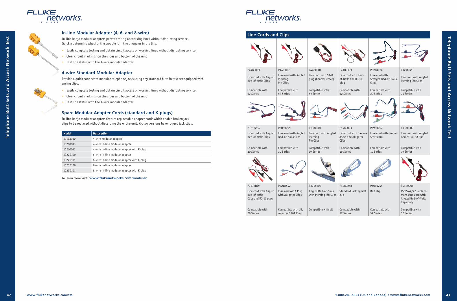
1-800-283-5853 (US and Canada) • www.flukenetworks.com42 43
In-line Modular Adapter (4, 6, and 8-wire)In-line banjo modular adapters permit testing on working lines without disrupting service. Quickly determine whether the trouble is in the phone or in the line.
• Easily complete testing and obtain circuit access on working lines without disrupting service
• Clear circuit markings on the sides and bottom of the unit
• Test line status with the 4-wire modular adapter
4-wire Standard Modular AdapterProvide a quick connect to modular telephone jacks using any standard butt-in test set equipped with spring clips.
• Easily complete testing and obtain circuit access on working lines without disrupting service
• Clear circuit markings on the sides and bottom of the unit
• Test line status with the 4-wire modular adapter
Spare Modular Adapter Cords (standard and K-plugs)In-line banjo modular adapters feature replaceable adapter cords which enable broken jack clips to be replaced without discarding the entire unit. K-plug versions have rugged jack clips.
Model Description
10113000 4-wire modular adapter
10210100 4-wire in-line modular adapter
10210101 4-wire in-line modular adapter with K-plug
10220100 6-wire in-line modular adapter
10220101 6-wire in-line modular adapter with K-plug
10230100 8-wire in-line modular adapter
10230101 8-wire in-line modular adapter with K-plug
To learn more visit: www.flukenetworks.com/modular
Teleph
on
e Bu
tt-Sets and
Access N
etwo
rk Test
Line Cords and Clips
P4480009 P4480001 P4480004 P4480RJ9 P3218024 P3218028
Line cord with Angled Bed-of-Nails Clips
Compatible with 52 Series
Line cord with Angled Piercing Pin Clips
Compatible with 52 Series
Line cord with 346A plug (Central Office)
Compatible with 52 Series
Line cord with Bed-of-Nails and RJ-11 plug
Compatible with 52 Series
Line cord with Straight Bed-of-Nails Clips
Compatible with 20 Series
Line cord with Angled Piercing Pin Clips
Compatible with 20 Series
P3218234 P3080009 P1980001 P1980003 P1980007 P1980009
Line cord with Angled Bed-of-Nails Clips
Compatible with 20 Series
Line cord with Angled Bed-of-Nails Clips
Compatible with 30 Series
Line cord with Angled Piercing Pin Clips
Compatible with 19 Series
Line cord with Banana Jacks and Alligator Clips
Compatible with 19 Series
Line cord with Ground Start cord
Compatible with 19 Series
Line cord with Angled Bed-of-Nails Clips
Compatible with 19 Series
P3218RJ9 P3218442 P3218202 P4080248 P4080249 P4480008
Line cord with Angled Bed-of-NailsClips and RJ-11 plug
Compatible with 20 Series
Line cord 471A Plug with Alligator Clips
Compatible with all,requires 346A Plug
Angled Bed-of-Nails with Piercing Pin Clips
Compatible with all
Standard locking belt clip
Compatible with 52 Series
Belt clip
Compatible with 52 Series
TS52/44/42 Replace-ment Line Cord with Angled Bed-of-Nails Clips Only
Compatible with 52 Series
Tele
ph
on
e B
utt
-Set
s an
d A
cces
s N
etw
ork
Tes
t
www.flukenetworks.com/tts
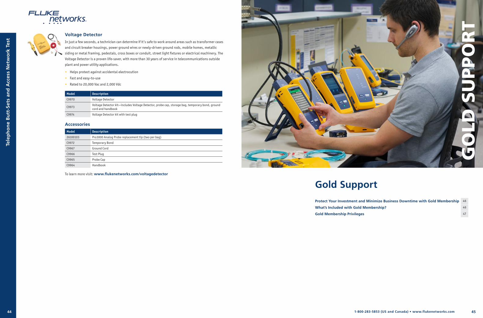
451-800-283-5853 (US and Canada) • www.flukenetworks.com44
Voltage Detector
In just a few seconds, a technician can determine if it’s safe to work around areas such as transformer cases
and circuit breaker housings, power ground wires or newly-driven ground rods, mobile homes, metallic
siding or metal framing, pedestals, cross boxes or conduit, street light fixtures or electrical machinery. The
Voltage Detector is a proven life-saver, with more than 30 years of service in telecommunications outside
plant and power utility applications.
• Helps protect against accidental electrocution
• Fast and easy-to-use
• Rated to 20,000 Vac and 2,000 Vdc
Model Description
C9970 Voltage Detector
C9973Voltage Detector kit—includes Voltage Detector, probe cap, storage bag, temporary bond, ground cord and handbook
C9974 Voltage Detector kit with test plug
Accessories
Model Description
26100103 Pro3000 Analog Probe replacement tip (two per bag)
C9972 Temporary Bond
C9967 Ground Cord
C9966 Test Plug
C9965 Probe Cap
C9964 Handbook
To learn more visit: www.flukenetworks.com/voltagedetector
Tele
ph
on
e B
utt
-Set
s an
d A
cces
s N
etw
ork
Tes
t
Gold Support
Protect Your Investment and Minimize Business Downtime with Gold Membership 46
What’s Included with Gold Membership? 46
Gold Membership Privileges 47
GO
LD S
UPP
OR
T
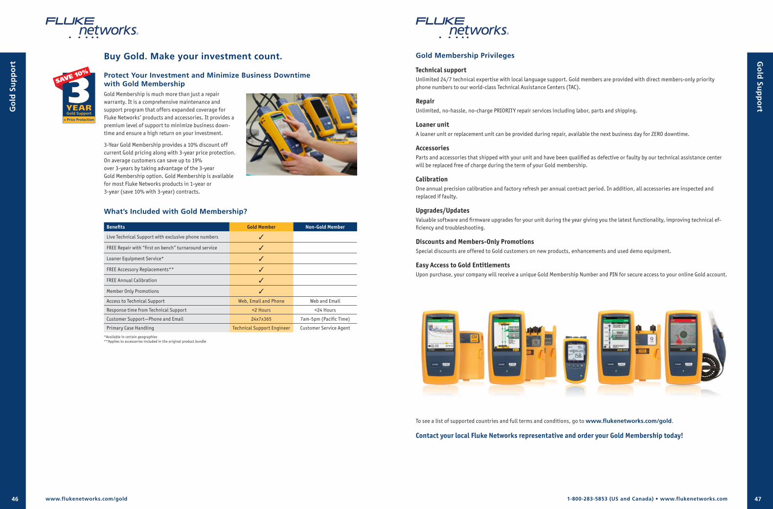
1-800-283-5853 (US and Canada) • www.flukenetworks.com46 47
Buy Gold. Make your investment count.
Protect Your Investment and Minimize Business Downtime with Gold MembershipGold Membership is much more than just a repair warranty. It is a comprehensive maintenance and support program that offers expanded coverage for Fluke Networks’ products and accessories. It provides a premium level of support to minimize business down-time and ensure a high return on your investment.
3-Year Gold Membership provides a 10% discount off current Gold pricing along with 3-year price protection. On average customers can save up to 19% over 3-years by taking advantage of the 3-year Gold Membership option. Gold Membership is available for most Fluke Networks products in 1-year or 3-year (save 10% with 3-year) contracts.
What’s Included with Gold Membership?
Benefits Gold Member Non-Gold Member
Live Technical Support with exclusive phone numbers 3
FREE Repair with “first on bench” turnaround service 3
Loaner Equipment Service* 3
FREE Accessory Replacements** 3
FREE Annual Calibration 3
Member Only Promotions 3
Access to Technical Support Web, Email and Phone Web and Email
Response time from Technical Support <2 Hours <24 Hours
Customer Support—Phone and Email 24x7x365 7am-5pm (Pacific Time)
Primary Case Handling Technical Support Engineer Customer Service Agent
*Available in certain geographies**Applies to accessories included in the original product bundle
www.flukenetworks.com/gold
Gold Membership Privileges
Technical supportUnlimited 24/7 technical expertise with local language support. Gold members are provided with direct members-only priority phone numbers to our world-class Technical Assistance Centers (TAC).
RepairUnlimited, no-hassle, no-charge PRIORITY repair services including labor, parts and shipping.
Loaner unitA loaner unit or replacement unit can be provided during repair, available the next business day for ZERO downtime.
AccessoriesParts and accessories that shipped with your unit and have been qualified as defective or faulty by our technical assistance center will be replaced free of charge during the term of your Gold membership.
CalibrationOne annual precision calibration and factory refresh per annual contract period. In addition, all accessories are inspected and replaced if faulty.
Upgrades/UpdatesValuable software and firmware upgrades for your unit during the year giving you the latest functionality, improving technical ef-ficiency and troubleshooting.
Discounts and Members-Only PromotionsSpecial discounts are offered to Gold customers on new products, enhancements and used demo equipment.
Easy Access to Gold EntitlementsUpon purchase, your company will receive a unique Gold Membership Number and PIN for secure access to your online Gold account.
Go
ld Su
pp
ortG
old
Su
pp
ort
To see a list of supported countries and full terms and conditions, go to www.flukenetworks.com/gold.
Contact your local Fluke Networks representative and order your Gold Membership today!
www.flukenetworks.com
Contact Us
CorporateFluke Networks Everett WA 98203, USA
Customer Service, Technical Support and Training1-800-283-5853 (Toll free inside U.S. and Canada)1-425-446-4519 (Worldwide)
Customer Service Email: [email protected] Email: [email protected] Email: [email protected]
Fluke Networks P.O. Box 777, Everett, WA USA 98206-0777
Fluke Networks operates in more than 50 countries worldwide. To find your local office contact details, go to www.flukenetworks.com/contact.
©2016 Fluke Corporation. Printed in U.S.A. 04/2016 3158212H
www.flukenetworks.com/facebook
www.flukenetworks.com/twitter
www.flukenetworks.com/linkedin
www.flukenetworks.com/youtube
Related Documents