CERTIFICATION TRAINING SUPPLEMENT FOR WASTEWATER TREATMENT PLANT OPERATORS Class II, III and IV Kentucky Department for Environmental Protection Division of Compliance Assistance Certification and Licensing Branch Operator Certification Program 300 Fair Oaks Lane Frankfort, Kentucky 40601

Welcome message from author
This document is posted to help you gain knowledge. Please leave a comment to let me know what you think about it! Share it to your friends and learn new things together.
Transcript
CERTIFICATION TRAINING SUPPLEMENT
FOR
WASTEWATER TREATMENT PLANT OPERATORS
Class II, III and IV
Kentucky Department for Environmental Protection
Division of Compliance Assistance Certification and Licensing Branch
Operator Certification Program 300 Fair Oaks Lane
Frankfort, Kentucky 40601
2002 2
TABLE OF CONTENTS
WASTEWATER CHARACTERISTICS ...........................................................................
BIOLOGICAL TREATMENT – DESIGN & OPERATIONAL CONSIDERATIONS..........................................................................................................
WASTEWATER COLLECTION SYSTEM......................................................................
PRELIMINARY TREATMENT........................................................................................
PRIMARY TREATMENT – SEDIMENTATION ............................................................
BIOLOGICAL TREATMENT – FIXED FILM OR ATTACHED GROWTH REACTORS........................................................................................................................
BIOLOGICAL TREATMENT – SUSPENDED GROWTH PROCESSES ......................
NITRIFICATION & DE-NITRIFICATION ......................................................................
SECONDARY SEDIMENTATION ..................................................................................
WASTE TREATMENT PONDS .......................................................................................
DISINFECTION BY CHLORINATION ...........................................................................
DE-CHLORINATION........................................................................................................
FLOW MEASUREMENT..................................................................................................
AEROBIC DIGESTION.....................................................................................................
ANAEROBIC DIGESTION...............................................................................................
SLUDGE HANDLING & DISPOSAL ..............................................................................
PUMPS & MOTORS..........................................................................................................
INDUSTRIAL WASTEWATER TREATMENT ..............................................................
ACTIVATED CARBON ADSORPTION..........................................................................
REFERENCES ...................................................................................................................
2002 3
CERTIFICATION TRAINING SUPPLEMENT WASTEWATER CHARACTERISTICS 1. Total solids make up approximately 0.1% of the total composition of domestic wastewater (700 – 1000 ppm). Total solids are composed of suspended and dissolved solids with colloidal solids making up a portion of both. Dissolved solids (400 – 700 ppm) consist of both organic and inorganic molecules and ions that are present in true solution in water (sulfates, chlorides, etc.). The colloidal fractions are very small solids that cannot be removed by physical settling. Total suspended solids (180 – 300 ppm) are the solids captured on the special filter when performing the TSS test as specified by Standard Methods For The Examination Of Water and Wastewater. Suspended solids can be further divided into settleable and colloidal solids where settleable solids are those solids, which will settle to the bottom of an imhoff cone in a 60 minute period and are normally removed by primary sedimentation. Approximately 70% of the suspended solids and 40% of the dissolved solids are organic in nature. 2. The biochemical oxygen demand, BOD5, is a measure of the organic strength with a range of 160 – 280 mg/l. The test can be roughly defined as a measurement of the dissolved oxygen used by microorganisms in the biochemical oxidation of organic matter. Most new KPDES permits now require measurement of CBOD5 (carbonaceous biochemical oxygen demand) where a nitrification inhibitor is added to suppress the oxidation of ammonia to nitrite and nitrate by two groups of autotrophic bacteria (Nitrosomonas & Nitrobackter). This assures that only the oxygen demand for organic matter will be measured. 3. Another measure of organic matter is the chemical oxygen demand, COD, which is normally in the range of 550 – 700 ppm. The COD test is quicker to perform and results are more reproducible than with the BOD5, test, but the BOD5 is the parameter required by the KPDES permit and is a better indicator of biological toxicity. 4. Total Kjeldahl Nitrogen is the sum of the organic nitrogen and ammonia nitrogen. Normal ranges for domestic wastewater are kjeldahl nitrogen (40 – 50 ppm), organic nitrogen (15-20 ppm), and ammonia nitrogen (25 – 30 ppm). During the biological treatment process, the nitrifying bacteria utilize approximately 7.2-ppm alkalinity per ppm ammonia nitrogen oxidized given adequate conditions for pH and temperature. The form of nitrogen found in a receiving stream generally indicates whether or not it was recently polluted. If most of the nitrogen found is in the form of organic or ammonia nitrogen, it was recently polluted. If most of the nitrogen found is in the form of nitrate, it was not recently polluted. 5. For relatively soft water, alkalinity normally is in the range of 100 – 125 ppm. Alkalinity in wastewater results from the presence of the hydroxides (OH), carbonates (CO3), and bicarbonates (HCO3) of elements such as calcium, magnesium, sodium, and potassium.
2002 4
BIOLOGICAL TREATMENT – DESIGN & OPERATIONAL CONSIDERATIONS 1. Population equivalents that are used to calculate hydraulic and organic loadings for domestic wastewater treatment if actual operating information is not available are as follows: BOD5 = 0.17 lbs./capita/day TSS = 0.20 lbs./capita/day Flow = 100 gallons/capita/day 2. Nutrient requirements for biological stabilization of organic matter result in following ratio: Carbon/Nitrogen/Phosphorus/Iron = C/N/P/Fe = 100/5/1/0.5 Another way of viewing this nutrient balance is to consider the BOD5 as the carbon source so that for every 100 ppm of BOD5 removed, there would have to be 5 ppm of nitrogen and 1 ppm of phosphorus available for cell synthesis. 3. If a nutrient deficiency exists, the biological process could suffer from filamentous growth problems. To obtain the necessary nutrients it may be necessary to add anhydrous ammonia for N, tri-sodium phosphate for P, or ferric chloride for Fe. Excessive filamentous growth results in bulking sludge, which will not settle well in secondary clarifiers. Other causes of filamentous sludge bulking in activated sludge plants include: Low dissolved oxygen. Low F/M = Food to Microorganism ratio. Low pH. Introduction of septic wastewater. Toxicity. 4. Other basic needs for biological metabolism include:
A. Dissolved oxygen = 2 to 3 ppm for activated sludge B. pH = 6.8 to 7.2
a. Balanced food supply = F/M which is process dependent but operator controlled.
C. Temperature controls the reaction rate. For example the metabolism reportedly drops by one half for a 10o drop in temperature (25o to 15o C).
D. Free from toxics – heavy metals, etc. E. Hydraulic influence – Processes are detention time dependent for adequate treatment.
Problems can be caused by: (1) short circuiting effects (object obstruction, un-level weirs, improper baffling, temperature gradients, etc.), or (2) incomplete mixing (aerators on low speed, diffusers turned down too low or clogged, inadequate horsepower, improper design, mud or chemical sludge dragging solids to the bottom, floating aerators on deep basins with no draft tubes, etc.).
F. Energy efficiency – It should always be considered. Wasting energy goes against principles of conservation and work output.
2002 5
5. Other influences, which can affect the biological treatment process, include sudden increases in organic loading on the system which are referred to as shock loads. A shock load may upset the nutrient balance as well as overwhelm the biological population. For example, septic tank hauling typically has a BOD5 of 2,000 to 6,000 mg/l and TSS concentration of 2-4% (20,000 – 40,000 mg/l). 6. Treatment plants sometimes receive spills or dumps of unknown origin referred to as slug loads which could be harmful to the treatment process and/or the operators. When discovered, as much information as possible should be obtained to identify the chemical nature, concentration, and volume of the spill. 7. Daily operations logs should also contain information on daily rainfall, temperature, and wastewater flows. This information may sometimes correlate to changes in the efficiency of the treatment process. The best method for presenting lab data and process control parameters such as F/M, MCRT, and MLSS so that it can be easily understood is through the use of trend charts and/or bar graphs.
WASTEWATER COLLECTION SYSTEM 1. Inflow/Infiltration is a major concern with most collection systems. Inflow is the excess rainwater that enters the system very soon after the rain begins and can normally be traced to unsealed manholes and illegal connections such as roof down spouts. Infiltration is the excess water that continues to enter the system for three or four day s after the rain has stopped and is the result of groundwater seeping into the system through breaks in the line and unsealed pipe joints. Inflow is usually more controllable and more easily eliminated. 2. Construction requirements limit the loss of waste from (or entrance of ground water into) a sewer system to 200 gallons per inch diameter per mile per day. This limitation is inclusive of manholes, sewer lines, and appurtenances. At least 30” of ground cover shall be provided for additional protection. As part of the construction, the integrity of a new system has to be verified by means of either the infiltration/exfiltration, or low-pressure air testing methods. An infiltration or exfiltration test shall be performed with a minimum positive head of two feet. 3. The infiltration test is generally preferred when the groundwater level is above the crown of the sewer. The upstream end of the section to be tested is plugged, and a flow-measuring device (weir, etc.) is installed in the manhole at the lower end. The rate of leakage can then be measured. 4. In the exfiltration test when ground water levels are too low to use the infiltration test, both ends of the section of sewer to be tested, including a manhole at each end, are plugged, and all stoppers and plugs are braced or otherwise secured to resist the internal pressure resulting from the test. The section is then filled with water to a predetermined level above the crown of the sewer, and the rate of leakage is computed on the basis of the observed drop in water level over a
2002 6
reasonably long period of time or by metering the volume of water to be supplied to the system to maintain the original water level. 5. In the air pressure test, a section between manholes is plugged and the plugs secured to withstand the expected internal pressure. Air is then introduced at a pressure above the maximum pressure exerted by any groundwater that may be present outside the pipe. After the air is shut off, the time it takes the pressure in the pipe section to drop by a pre-designated amount is determined. Manholes should be tested separately. 6. Sewer lines, when flowing full, should have a mean velocity of not less than 2.0 fps (feet per second) to reduce the possibility of solids deposition in the collection system.
PRELIMINARY TREATMENT 1. Screening: The first unit found at treatment plants is used to remove trash and coarse solids (wood, cloth, paper, plastics, garbage, etc.). Screening devices may consist of parallel bars, gratings, wire mesh, or perforated slots. The parallel bar or rod configuration is called a trash rack or bar screen and will have openings (space between bars) of ⅝” or more. The 1990 edition of “Recommended Standards for Wastewater Facilities of the Great Lakes-Upper Mississippi River Board of State Public Health and Environmental Managers” (commonly referred to as “Ten States’ Standards”) lists these as coarse screens. This publication recommends openings for manually cleaned bar racks be from 1” to 1¾” and placed on a slope of 30 to 45 degrees from the horizontal. It also recommends approach velocities be at least 1.25 fps to prevent settling and not more than 3.0 fps to prevent forcing material through the openings. The term “screen” is used for screening devices consisting of perforated plates, wedge wire elements, and wire cloth and the openings will be less than ⅝”. “Ten States’ Standards” refers to screens with openings of approximately 1/16 inch as fine screens that can be used in lieu of primary sedimentation. Commonly used screens include the hydro sieve or inclined fixed screen and the rotary drum screen. A primary concern of screening devices is the potential head loss through them, which increases with the degree of clogging. If they are not self cleaning; it is imperative that the operator clean them several times each day to prevent a damming effect that results in grit being deposited upstream from the unit. Where fine screens are used, consideration should be given to the prior removal of floatable oils and greases, which can clog the openings. 2. Grit Removal: These units are designed to remove grit or other heavy solid material that have subsiding velocities or specific gravities substantially greater than those of the organic putrescible solids in wastewater. In addiction to grit consisting of sand, gravel, and cinders, other materials removed include eggshells, bone chips, seeds, coffee grounds, and large organic particles such as food wastes. Generally, grit removed is relatively dry and inert, but it can be highly variable with a volatile content up to 56%. The specific gravity of clean, inert grit particles may be as high as 2.7 but can be as low as 1.3 when substantial organic material is mixed in. Removing the grit helps to prevent damage to downstream equipment such as pump impellers. Also, if the grit is allowed to settle in subsequent treatment units, space is taken up that reduces the treatment capacity of those units. Grit removal should be provided for all wastewater treatment plants, especially for those receiving wastewater from combined sewers.
2002 7
There are three general types of grit chambers; horizontal-flow channels, aerated, and vortex-type. In the horizontal channel, velocities are reduced to 1-1.5 fps so that the grit will settle while the organics remain in suspension. The velocity is controlled by special influent distribution gates, dimensions of the unit, and special weir sections (proportional, sutro, etc.) at the effluent end. The aerated type consists of a spiral-flow aeration tank where the spiral velocity is induced and controlled by the tank dimensions and quantity of air supplied to the unit. Aeration rates are adjustable in the range of 3-8 CFM (cubic feet per minute) per foot of tank length. Increasing the aeration rate helps to prevent the organic material from settling out. Detention times range from 3 to 5 minutes at design peak hourly flows. The vortex-type unit (Pista Grit, etc.) consists of a cylindrical tank in which the flow enters tangentially creating a vortex-flow pattern; centrifugal and gravitational forces cause the grit to separate. 3. Comminution: As an alternative to racks or coarse screens, comminutors are sometimes used to grind coarse solids without removing them from the flow stream. They are found mainly in smaller communities and should follow the grit removal process to prolong the life of the equipment and reduce the wear on the cutting surfaces. If the comminutor precedes grit removal, the cutting teeth will require frequent sharpening or replacement. Units usually consist of a vertical stationary section and an oscillating or rotating section equipped with cutting teeth. The close tolerance between the shear bars and cutting teeth allow solids to be cut into smaller, more uniform size, which are taken out by subsequent treatment stages. If the cutting adjustment is improper, the solids will not be cut cleanly or shredded as desired. 4. Flow Equalization: Used to smooth out wide variations in flow so that a constant or nearly constant flow-rate can be achieved, flow equalization improves the performance of the downstream processes and reduces the size and cost of downstream treatment facilities. They can be either in-line units where all the flow passes through the basin or off-line units where only the flow above some predetermined rate is diverted into the basin. The off-line basin is commonly used to capture the first flush from the combined sewers while the in-line basic must be used if equalization of the plant loadings is also desired. Primary considerations in the operation include pump control systems, mixing, and aeration requirements. The mixing equipment has to be adequate to prevent deposition of solids in the basin. Aeration is needed to prevent the wastewater from becoming septic and odorous. [1] “Ten States’ Standards” recommends a minimum of 1.25 CFM per 1000 gallons of storage capacity.
PRIMARY TREATMENT – SEDIMENTATION 1. Design Parameters: Detention Time = 1.5 to 2.0 hours Weir Overflow Rate = 5,000 to 15,000 gpd/ft Surface Loading Rate = 600 to 800 gpd/ft2
2. Expected Removal Efficiency: BOD5 = 25 – 40% TSS = 40 – 60% Settleable Solids = 90 – 95%
2002 8
3. Operations: The purpose of primary settling is to create a relatively quiescent area where solids having a higher specific gravity than the liquid will tend to settle, and those with a lower specific gravity will tend to rise so that readily settleable solids and floating material such as grease can be removed and reduce the load on the subsequent biological treatment units. Regular preventive maintenance on mechanical equipment is necessary to prevent breakdowns such as broken flights and locked speed reducer gears. Sludge accumulating in the clarifier will normally concentrate to 4-8% before being transferred to the digester. Small quantities of sludge should be pumped often (1) to prevent hydraulic & organic overloading of the digester, and (2) to keep sludge blankets down so that septic “floating” sludge will not result. The best way to determine sludge blanket depth, to insure that sufficient quantities are being removed, is to measure it with a sludge judge, sludge core taker, or sludge blanket finder. By knowing the concentration of sludge and the gallons pumped, pounds of sludge transferred to the thickener or digester can be calculated. If there is no flow-measuring device, the sludge pumping rate must be determined and the time in minutes that the pump operates to transfer sludge is then used to determine gallons pumped. The pounds wasted can also be compared with the pounds captured by the primary clarifier to see if waste sludge rates are sufficient. “Ten States’ Standards” recommends a minimum water depth for primary clarifiers of seven feet. Primary clarification normally precedes biological treatment using fixed film reactors or the conventional activated sludge process but is not used for the extended aeration process.
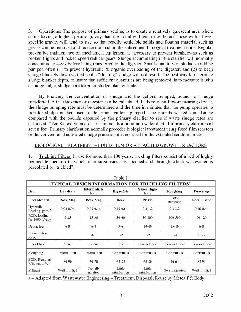
BIOLOGICAL TREATMENT – FIXED FILM OR ATTACHED GROWTH REACTORS 1. Trickling Filters: In use for more than 100 years, trickling filters consist of a bed of highly permeable medium to which microorganisms are attached and through which wastewater is percolated or “trickled”.
Table 1 TYPICAL DESIGN INFORMATION FOR TRICKLING FILTERSa
Item Low-Rate Intermediate Rate High-Rate Super High-
Rate Roughing Two-Stage
Filter Medium Rock, Slag Rock, Slag Rock Plastic Plastic, Redwood Rock, Plastic
Hydraulic Loading, gpm/ft2 0.02-0.06 0.06-0.16 0.16-0.64 0.2-1.2 0.8-3.2 0.16-0.64
BOD5 loading lbs/1000 ft3/day 5-25 15-30 30-60 30-100 100-500 60-120
Depth, feet 6-8 6-8 3-6 10-40 15-40 6-8
Recirculation Ratio 0 0-1 1-2 1-2 1-4 0.5-2
Filter Flies Many Some Few Few or None Few or None Few or None
Sloughing Intermittent Intermittent Continuous Continuous Continuous Continuous
BOD5 Removal Efficiency, % 80-90 50-70 65-85 65-80 40-65 85-95
Effluent Well nitrified Partially nitrified
Little nitrification
Little nitrification No nitrification Well nitrified
a – Adapted from Wastewater Engineering – Treatment, Disposal, Reuse by Metcalf & Eddy.
2002 9
The efficiency of a trickling filter operation is most commonly measured by the percent removal of BOD5 and/or COD. Recirculation as indicated above is sometimes used with trickling filters to (a) keep the distributor arm in motion and the media from drying out during low flow periods, (b) dilute the organic strength of the influent, (c) smooth out diurnal flow fluctuations, and (d) increase the contact time with the media and help to seed the lower portions of the filter with active microorganisms. For filters using plastic media, “Ten States’ Standards” limits the void area to no more than 30 ft2 per cubic feet of volume for filters used for carbonaceous reduction and 45 ft2 per cubic feet of volume for second stage ammonia reduction. The under drain system is important so that free passage of air is available. The size of the drains, channels, and pipe should be such that not more than 50% of their cross-sectional area will be submerged under the design peak instantaneous flow, including proposed or possible future re-circulated flows according to “Ten States’ Standards”. 2. Rotating Biological Contactors (RBCs): First used in West Germany in 1960 and later introduced in the U.S., the RBC process utilizes plastic disc filter media mounted on a long, horizontal, rotating shaft.
A. Shaft lengths are limited to 27 ft. with 25 ft. occupied by the media. Typical rotational speeds range from 1.5 to 1.6 rpm. With a media diameter of 12 ft., the peripheral speed is approximately 60 ft./minute.
B. The media is normally 40% submerged with tank depths averaging about 5 ft. The
treatment process normally has two or more RBC units operating in series that are referred to as stages. A minimum of 2 to 3 stages are usually necessary to reliably achieve secondary BOD5 limits, and 3 to 4 stages are required to achieve an effluent BOD5 less than 20 mg/l. Additional stages would need to be added to achieve nitrification. Standard density media containing 100,000 ft2 of surface area per shaft is used on the first stages for BOD5 removal. High-density media containing from 120,000 to 180,000 ft2 of surface area per shaft is used on the later stages of nitrification.
C. Dissolved oxygen (D.O.) concentrations as a minimum should range from 0.5 to 1.0 mg/l at the end of the first stage and at least 2 to 3 mg/l at the end of the last stage. Plants designed for nitrification often operate to attain a 4 to 5 coupled with excessive hydrogen sulfide concentrations can result in a white or gray biomass on the filter media. A healthy first-stage biomass is uniformly brown and distributed in a thin, even layer. The biomass on the later stages tends to have a gold or reddish sheen. A heavy, shaggy biomass in the first stage indicates an organic overload. To improve D.O. concentrations and sloughing of the biomass, some of the earlier installations have been retrofitted with diffused aeration which can also eliminate solids accumulations in the basin’s dead zones.
2002 10
D. Hydraulic loadings should not exceed design loadings by more then 50% due to
shortened detention times (0.12 gallons of tank volume per ft2 of media), and the fact that this is a once through process without sludge recycle.
E. Recirculation of RBC-treated effluent does not significantly improve treatment
efficiency and is not normally used. If it is used, recirculation through sludge holding or thickening tanks is to be avoided because the sludge could produce high sulfide concentrations in the recycle flow that would stimulate the growth of the aforementioned nuisance organisms.
F. Covers or enclosures are used with RBCs to (1) protect biological slimes from freezing, (2) prevent rain from washing off slime growths, (3) prevent exposure of media to sunlight resulting in algae growth, (4) avoid weakening the plastic media from ultraviolet rays, and (5) provide protection from the elements.
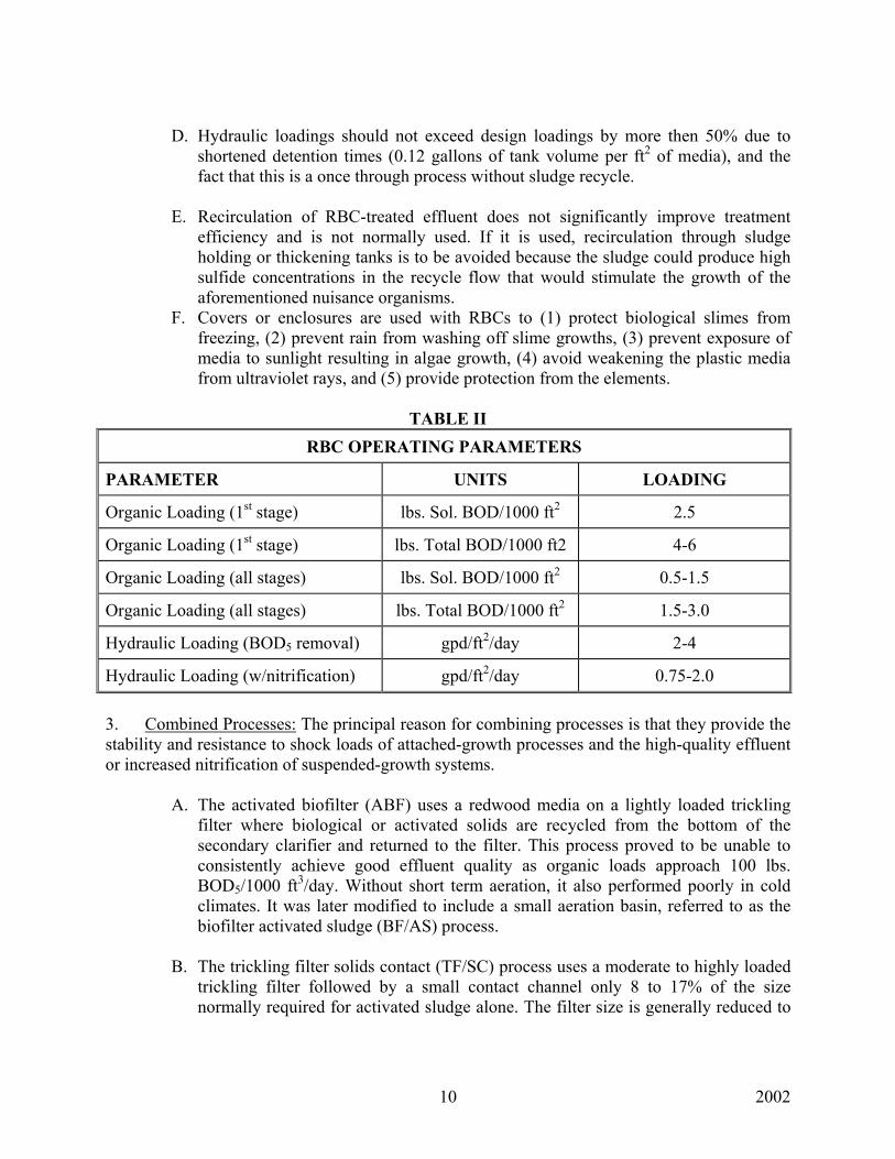
TABLE II
RBC OPERATING PARAMETERS
PARAMETER UNITS LOADING
Organic Loading (1st stage) lbs. Sol. BOD/1000 ft2 2.5
Organic Loading (1st stage) lbs. Total BOD/1000 ft2 4-6
Organic Loading (all stages) lbs. Sol. BOD/1000 ft2 0.5-1.5
Organic Loading (all stages) lbs. Total BOD/1000 ft2 1.5-3.0
Hydraulic Loading (BOD5 removal) gpd/ft2/day 2-4
Hydraulic Loading (w/nitrification) gpd/ft2/day 0.75-2.0 3. Combined Processes: The principal reason for combining processes is that they provide the stability and resistance to shock loads of attached-growth processes and the high-quality effluent or increased nitrification of suspended-growth systems.
A. The activated biofilter (ABF) uses a redwood media on a lightly loaded trickling filter where biological or activated solids are recycled from the bottom of the secondary clarifier and returned to the filter. This process proved to be unable to consistently achieve good effluent quality as organic loads approach 100 lbs. BOD5/1000 ft3/day. Without short term aeration, it also performed poorly in cold climates. It was later modified to include a small aeration basin, referred to as the biofilter activated sludge (BF/AS) process.
B. The trickling filter solids contact (TF/SC) process uses a moderate to highly loaded
trickling filter followed by a small contact channel only 8 to 17% of the size normally required for activated sludge alone. The filter size is generally reduced to

2002 11
50% or less of that required with a trickling filter alone. From 60 to 85% of the BOD5 is removed in the filter.
C. The roughing filter activated sludge (RF/AS) process is sometimes used to upgrade
existing activated sludge plants by installing a roughing filter ahead. Similar to the TF/SC process, it operates at higher total organic loadings. Although it has the same flow schematic as the TF/SC, the RF/AS uses a much smaller trickling filter and depends more on the aeration basin to provide oxygen, remove BOD5, and digest solids.
D. The biofilter activated sludge (BF/AS) process resembles the TF/SC or the RF/AS
processes except that all the return activated sludge from the clarifier is recycled over the trickling filter in a similar fashion to that of the ABF process. In the TF/SC or RF/AS processes, the return sludge flow is routed to the underflow stream from the trickling filter where a portion is recycled across the filter and the remainder goes directly to the aeration basin.
E. The series trickling filter activated sludge (TF/AS) process differs from the others
in that an intermediate clarifier is located between the trickling filter and the aeration basin. The intermediate clarifier removes sloughed solids from the trickling filter underflow before it enters the aeration basin so that solids can be separated from the second-stage treatment. This results in the second stage being dominated by nitrifying microorganisms. Reduced oxygen requirements or improved sludge settle ability, however, has not been demonstrated. Therefore, unless substantial nitrification is required, the RF/AS or BF/AS processes are normally used with high rate roughing filters to eliminate the cost of intermediate clarification.
BIOLOGICAL TREATMENT – SUSPENDED GROWTH PROCESSES
Suspended growth processes are biological treatment processes which use mechanical aerators or diffused aeration to provide mixing action in the reactor basin to (1) keep solids in suspension, (2) help bring the food (BOD5) and microorganisms (MLVSS) together, and (3) disperse oxygen throughout the basin. The three principal suspended growth biological processes used for secondary treatment are the activated sludge process, aerated lagoons, and sequencing batch reactors (SBCs). SBCs are essentially activated sludge processes which are operated in a fill-and-draw mode. Aeration and sedimentation are carried out simultaneously in separate tanks. At this time, SBCs are not commonly found in Kentucky. Lagoons are discussed separately later in this supplement. For the activated sludge process, the shape and number of aeration tanks can be modified to vary the flow pattern as complete-mix or plug flow. 1. Complete Mix: In this process, the characteristics of the mixed liquor are similar throughout the aerations basin (small length to width ratio). Because the tank contents are similar, there is a very low level of food available at any time to a large mass of microorganisms which is an advantage in handling surges in organic loadings without producing a change in effluent quality. A disadvantage is that it is more prone to filamentous bulking. Selectors, or
2002 12
small contact tanks preceding the main aeration tank, are sometimes used to provide initial conditioning to reduce bulking problems. 2. Plug Flow: This is the conventional activated sludge process where the aeration basin has a high length to width ratio. The MLSS in the initial part of the tank has a high organic load. The loading then decreases as the organic material in the raw wastewater is oxidized. In the latter half o the tank, depending on detention time, the oxygen consumption may primarily result from nitrification or endogenous respiration, the phenomenon whereby microorganisms metabolize their own cellular mass. Aeration is generally tapered or reduced toward the effluent end of the basin while a complete mix configuration must operate at a high D.O. for the entire tank. 3. Contact Stabilization: This process has a short term contact tank followed by a clarifier. The return sludge is routed to a sludge stabilization or re-aeration tank with about six times the detention time as the contact tank. Mixed liquor from the re-aeration basin is then routed to the head of the contact tank to mix with the influent. Tank size requirements are typically 50% less than required for conventional plug flow systems. 4. Step Feed: A modification of the plug flow configuration, the influent is fed at two or more points along the length of the aeration basin to equalize the F/M ratio, thus lowering the peak oxygen demand. With this arrangement, oxygen uptake requirements are relatively even and the need for tapered aeration is eliminated. 5. Extended Aeration: The process uses the same flow pattern as conventional plug flow processes but operates in the endogenous respiration phase with long detention times of 18 hours or more with low organic loadings. A disadvantage is the greater oxygen requirement versus the conventional activated sludge process. However, the capital cost for primary clarification is eliminated which is a required component of the conventional activated sludge process. 6. Oxidation Ditch: A variation of the EA process, the wastewater typically flows along a circular or oval path. Mechanical aerators (horizontal axis type) provide oxygen and mixing action and move the MLSS along the pathway. Velocity is maintained between 0.8 and 1.2 ft/second in the channel to prevent solids settling. 7. High Purity Oxygen: Oxygen is used instead of air in the process in tanks that are covered. The amount of oxygen that is added is about 4 times greater than can be added with conventional aeration systems. 8. Modified Aeration: This process is similar to the conventional plug flow process except that shorter aeration times and higher F/M ratios are used. Removal efficiencies are also less. 9. Kraus Process: A variation of the step aeration process used to treat wastewater with low nitrogen levels, digester supernatant is added as a nutrient source to a portion of the return sludge in a separate aeration tank designed to nitrify. The resulting mixed liquor is then added to the main plug flow aeration system.
2002 13
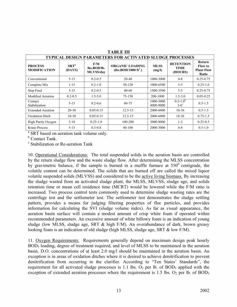
TABLE III TYPICAL DESIGN PARAMETERS FOR ACTIVATED SLUDGE PROCESSES
PROCESS MODIFICATION
SRTa (DAYS)
F/M lbs.BOD/lb. MLVSS/day
ORGANIC LOADING (lbs.BOD/1000 ft3.)
MLSS (mg/l)
DETENTION TIME
(HOURS)
Return Flow to
Plant Flow Ratio
Conventional 5-15 0.2-0.5 20-40 1000-3000 4-8 0.25-0.75
Complete Mix 1-15 0.2-1.0 50-120 1000-6500 3-5 0.25-1.0
Step Feed 3-15 0.2-0.5 40-60 1500-3500 3-5 0.25-0.75
Modified Aeration 0.2-0.5 1.5-5.0 75-150 200-1000 1.5-3.0 0.05-0.25 Contact Stabilization 5-15 0.2-0.6 60-75 1000-3000
4000-9000 0.5-1.0b
3-6c 0.5-1.5
Extended Aeration 20-30 0.05-0.15 12.5-15 2000-6000 18-36 0.5-1.5
Oxidation Ditch 10-30 0.05-0.15 12.5-15 2000-6000 18-36 0.75-1.5
High Purity Oxygen 3-10 0.25-1.0 100-200 3000-8000 1-3 0.25-0.5
Kraus Process 5-15 0.3-0.8 40-100 2000-3000 4-8 0.5-1.0 a SRT based on aeration tank volume only. b Contact Tank. c Stabilization or Re-aeration Tank 10. Operational Considerations: The total suspended solids in the aeration basin are controlled by the return sludge flow and the waste sludge flow. After determining the MLSS concentration by gravimetric balance, if the sample is burned in a muffle furnace at 5500 centigrade, the volatile content can be determined. The solids that are burned off are called the mixed liquor volatile suspended solids (MLVSS) and considered to be the active living biomass. By increasing the sludge wasted from an activated sludge plant, the MLSS, MLVSS, sludge age, and solids retention time or mean cell residence time (MCRT) would be lowered while the F/M ratio is increased. Two process control tests commonly used to determine sludge wasting rates are the centrifuge test and the settlometer test. The settlometer test demonstrates the sludge settling pattern, provides a means for judging filtering properties of floc particles, and provides information for calculating the SVI (sludge volume index). As far as visual appearance, the aeration basin surface will contain a modest amount of crisp white foam if operated within recommended parameters. An excessive amount of white billowy foam is an indication of young sludge (low MLSS, sludge age, SRT & high F/M). An overabundance of dark, brown greasy looking foam is an indication of old sludge (high MLSS, sludge age, SRT & low F/M). 11. Oxygen Requirements: Requirements generally depend on maximum design peak hourly BOD5 loading, degree of treatment required, and level of MLSS to be maintained in the aeration basin. D.O. concentrations of at least 2.0 mg/l should be maintained in the aeration basin. An exception is in areas of oxidation ditches where it is desired to achieve denitrification to prevent denitrification from occurring in the clarifier. According to “Ten States’ Standards”, the requirement for all activated sludge processes is 1.1 lbs. O2 per lb. of BOD5 applied with the exception of extended aeration processes where the requirement is 1.5 lbs. O2 per lb. of BOD5
2002 14
applied to include endogenous respiration requirements. If ammonia removal is required, an additional oxygen requirement of 4.6 lbs. O2 per lb. of total kjeldahl nitrogen (TKN) applied is required. For diffused aeration systems, the air requirements can be determined using equations which take into account oxygen transfer efficiencies and oxygen saturation values at various temperatures and altitudes or assumed to be 1500 ft3. per lb. Of BOD5 applied for all but extended aeration processes where the value is 2050 ft3./lb. BOD5. To this amount will be added additional air requirements for digesters and air-lift pumps. NITRIFICATION & DENITRIFICATION 1. Requirements for Biological Nitrification: A. Organic Loading: 10 lbs. NH3-N/1000 ft3.volume/day @ 2000 ppm MLVSS, 10o C. B. Solids Retention Time: At least a 10 day sludge age is needed for nitrification to begin. C. Alkalinity: 7.2 ppm needed to convert 1 ppm NH3-N to NO3.
D. pH: Optimum nitrification occurs at range of 7.8 to 9.0 but will occur at lower pH ranges.
E. Freedom from toxics: nitrifiers are more sensitive & slower to multiply than the heterotrophic microorganisms which oxidize carbonaceous matter.
F. Dissolved Oxygen: It should be at least 2 to 3 ppm.
G. Temperature: Nitrification increases with higher temperatures. For example, when MLVSS = 2000 ppm @ 10o C, Organic loading = 10 lbs. NH3/ 1000 ft3. of volume. @ 20o C, Organic loading = 25 lbs. NH3/ 1000 ft3. of volume.
H. Chlorination: It takes approximately 9.0 ppm chlorine to oxidize 1.0 ppm ammonia assuming adequate pH, alkalinity, and temperature.
2. Denitrification: Denitrification is the biological conversion of nitrite (NO2) and nitrate (NO3) to nitrogen gas (N2) or other reduced forms such as N2O or NO by facultative heterotrophs which can utilize nitrate instead of free oxygen as their oxygen source. This process takes place under anoxic, or near anaerobic conditions, when dissolved oxygen concentrations are near zero. In secondary clarifiers with high sludge blankets and long detention times, this process is sometimes observed by the presence of nitrogen gas bubbles floating to the surface and bringing the sludge blanket up with them. To prevent this occurrence, D.O. concentrations in the aeration basin MLSS entering the clarifier should be at least 2.0 ppm and sludge blankets should be kept below 3 feet. Some oxidation ditches are now designed to achieve denitrification rather than allowing it to become a problem in the clarifier. This is done by creating an area in the ditch upstream of the aerators where low D.O. concentrations are encouraged.
2002 15
KPDES permits currently do not impose nitrate limits so denitrification is not required on conventional treatment systems. However, a treatment system designed for denitrification requires a carbon source, usually methanol (CH3OH), for the reaction to proceed. As a cost saving measure, the influent BOD5 can be used as the carbon source. Reaction rates are most rapid for methanol, then soluble BOD5, slower for colloidal matter, and slowest for endogenous metabolism. During the nitrification process alkalinity is consumed, however, during the deinitrification process alkalinity is actually produced. For each 1 ppm of nitrate nitrogen that is denitrified to nitrogen gas, 3.57 ppm of calcium carbonate alkalinity is produced. Another benefit of the denitrificatioin process is the reuse of the oxygen in the nitrate molecule. Theoretically, 67% of that oxygen can be used to oxidize organics. Therefore, dissolved oxygen used to convert ammonium nitrogen into nitrate in the aerobic zone is recovered during subsequent denitrification. SECONDARY SEDIMENTATION 1. Sedimentation is the gravity settling from water of suspended solids which are heavier than water. There are generally considered to be four types of settling, and it is common to have more than one type occurring at the same time:
A. Type 1 – Discrete Particle: Refers to the sedimentation of particles in a suspension of low solids concentration. Particles settle as individual entities, and there is no significant interaction with neighboring particles. Example – Removal of grit and sand particles from wastewater.
B. Type 2 – Flocculant: Refers to a rather dilute suspension of particles that coalesce, or flocculate, during the sedimentation operation. By coalescing, the particles increase in mass and settle at a faster rate. Example – Removal of portion of suspended solids in untreated wastewater in primary settling facilities, and in upper portions of secondary settling facilities; also removes chemical floc in settling basins.
C. Type 3 – Hindered, also called Zone: Refers to suspensions of intermediate concentration, in which inter-particle forces are sufficient to hinder the settling of neighboring particles. The particles tend to remain in fixed positions with respect to each other, and the mass of particles settles as a unit. A solids-liquid interface develops at the top of the settling mass. Example – Occurs in secondary settling facilities used in conjunction with biological treatment facilities.
D. Type 4 – Compression: refers to settling in which the particles are of such concentration that a structure is formed, and further settling can occur only by compression of the structure. Compression takes place from the weight of the particles, which are constantly being added to the structure by sedimentation from the supernatant liquid. Example – Usually occurs in the lower layers of a deep sludge mass, such as in the bottom of deep secondary settling facilities and in sludge-thickening facilities.
2. Operational Considerations: Multiple clarifiers capable of independent operation are recommended by “Ten States’ Standards” for facilities where design average flows exceed
2002 16
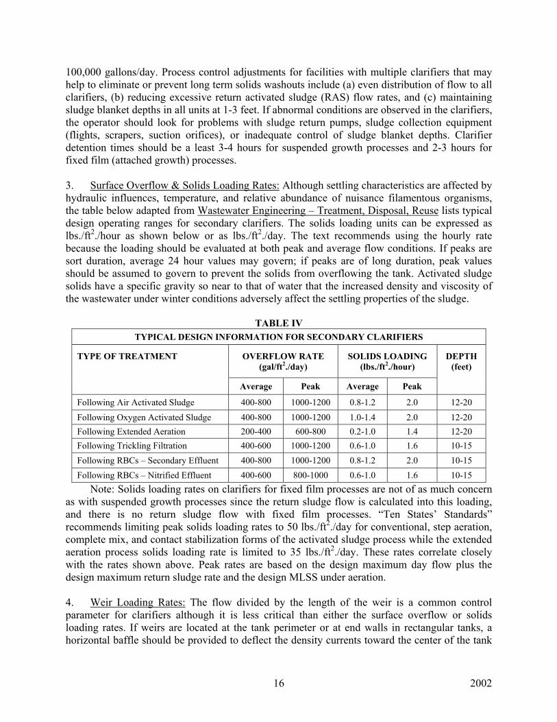
100,000 gallons/day. Process control adjustments for facilities with multiple clarifiers that may help to eliminate or prevent long term solids washouts include (a) even distribution of flow to all clarifiers, (b) reducing excessive return activated sludge (RAS) flow rates, and (c) maintaining sludge blanket depths in all units at 1-3 feet. If abnormal conditions are observed in the clarifiers, the operator should look for problems with sludge return pumps, sludge collection equipment (flights, scrapers, suction orifices), or inadequate control of sludge blanket depths. Clarifier detention times should be a least 3-4 hours for suspended growth processes and 2-3 hours for fixed film (attached growth) processes. 3. Surface Overflow & Solids Loading Rates: Although settling characteristics are affected by hydraulic influences, temperature, and relative abundance of nuisance filamentous organisms, the table below adapted from Wastewater Engineering – Treatment, Disposal, Reuse lists typical design operating ranges for secondary clarifiers. The solids loading units can be expressed as lbs./ft2./hour as shown below or as lbs./ft2./day. The text recommends using the hourly rate because the loading should be evaluated at both peak and average flow conditions. If peaks are sort duration, average 24 hour values may govern; if peaks are of long duration, peak values should be assumed to govern to prevent the solids from overflowing the tank. Activated sludge solids have a specific gravity so near to that of water that the increased density and viscosity of the wastewater under winter conditions adversely affect the settling properties of the sludge.
TABLE IV TYPICAL DESIGN INFORMATION FOR SECONDARY CLARIFIERS
TYPE OF TREATMENT
OVERFLOW RATE (gal/ft2./day)
SOLIDS LOADING (lbs./ft2./hour)
DEPTH (feet)
Average Peak Average Peak
Following Air Activated Sludge 400-800 1000-1200 0.8-1.2 2.0 12-20
Following Oxygen Activated Sludge 400-800 1000-1200 1.0-1.4 2.0 12-20 Following Extended Aeration 200-400 600-800 0.2-1.0 1.4 12-20 Following Trickling Filtration 400-600 1000-1200 0.6-1.0 1.6 10-15 Following RBCs – Secondary Effluent 400-800 1000-1200 0.8-1.2 2.0 10-15 Following RBCs – Nitrified Effluent 400-600 800-1000 0.6-1.0 1.6 10-15
Note: Solids loading rates on clarifiers for fixed film processes are not of as much concern as with suspended growth processes since the return sludge flow is calculated into this loading, and there is no return sludge flow with fixed film processes. “Ten States’ Standards” recommends limiting peak solids loading rates to 50 lbs./ft2./day for conventional, step aeration, complete mix, and contact stabilization forms of the activated sludge process while the extended aeration process solids loading rate is limited to 35 lbs./ft2./day. These rates correlate closely with the rates shown above. Peak rates are based on the design maximum day flow plus the design maximum return sludge rate and the design MLSS under aeration. 4. Weir Loading Rates: The flow divided by the length of the weir is a common control parameter for clarifiers although it is less critical than either the surface overflow or solids loading rates. If weirs are located at the tank perimeter or at end walls in rectangular tanks, a horizontal baffle should be provided to deflect the density currents toward the center of the tank
2002 17
and away from the effluent weir. Circular clarifiers should be equipped with center diffusion wells with a minimum diameter of 25% of the overall tank diameter for the dissipation of the influent energy and the distribution of the incoming mixed liquor. Weir loading rates (WLR) should not exceed 30,000 gpd/ft. at maximum flow for large tanks or 20,000 gpd/ft. for small tanks. At average flows, the WLR should be 10,000 gpd/ft. or less for small clarifiers. The upflow velocity in the immediate vicinity of the weir should be limited to 12-24 ft /hour. WASTE TREATMENT PONDS 1. Types & Application:
A. Stabilization ponds – Ponds designed to receive wastes with no prior treatment, also referred to as “raw wastewater (sewage) lagoons”.
B. Oxidation ponds – Ponds used in series following primary treatment to provide additional clarification, BOD removal, and disinfection.
C. Polishing ponds – Ponds used in series following secondary treatment (trickling filters), thus providing a form of “tertiary treatment”.
2. Pond Classifications: A. Aerobic ponds – Dissolved oxygen is distributed throughout the pond practically all of the time. Oxygen may be provided by algae during the daylight hours, mechanical surface aerators, or by diffused aeration provided by compressors. B. Anaerobic ponds – There is a lack of dissolved oxygen throughout the entire depth. Treatment depends upon fermentation of the sludge on the pond floor. They are used mainly for processing industrial wastes, but facultative domestic-waste ponds can become anaerobic if organically overloaded. C. Facultative ponds – These are the most common type. They are usually 4 to 5 feet deep with the upper 2 feet being aerobic while the bottom 2 or 3 feet is anaerobic. Algae provide most of the oxygen for the upper portion of the pond. 3. Detention Times: - Facultative Ponds A. 3 days – Pond will perform similar to a sedimentation basin. Some growth of algae will occur, but it will not have a major effect on the treatment of the wastewater. B. 3 to 20 days – Prolific growth of algae with large amounts being carried over in the effluent. Organic material in the effluent may exceed organic content of the influent. C. 60 days – This is the amount of time necessary to establish a thriving biological population for waste reduction. Removals of 90 to 95% of coliform bacteria and 70 to 80% of BOD load can be achieved approximately 80% of the time.

2002 18
D. 180 days – Controlled discharge ponds. Removal efficiencies up to 85 to 95% for BOD5 and TSS and 99% for fecal coliform can be achieved. 4. Algal Growth: A. Dissolved nutrient materials obtained from compounds containing nitrogen and phosphorus along with carbon dioxide (CO2) and bicarbonate (HCO3) are utilized in the metabolism of algal cells to build body protoplasm. Like land plants, they release oxygen and some carbon dioxide as waste products. B. Each pound of algae in a healthy pond is capable of producing 1.6 pounds of oxygen on a normal summer day by utilizing sunlight through photosynthesis. This is the process in which organisms with the aid of chlorophyll (green plant enzyme) convert carbon dioxide and inorganic substances to oxygen and additional plant material utilizing sunlight for energy. C. The oxygen produced by the algae is then available for the aerobic bacteria to utilize in the breakdown of organic matter to carbon dioxide and ammonia which is then utilized by the algae in a continuous cycle. D. During photosynthesis in the daylight hours, dissolved oxygen levels and pH will increase. At night, both will drop since CO2, is no longer being converted to free oxygen. E. During winter months when ponds are covered with ice and snow, sunlight is no longer available for the algae, and dissolved oxygen cannot enter the water from the atmosphere. Odorous gases will then accumulate under the ice that is the result of anaerobic decomposition of the wastes. F. Methods used to reduce odors in ponds have included (1) use of floating aerators, (2) recirculation from aerobic units, (3) use of odor masking chemicals, and (4) heavy chlorination. Chlorination is usually not recommended because it will interfere with the biological stabilization of the wastes. G. Sodium Nitrate is one of the most common chemicals used as a source of oxygen for microorganisms in ponds to prevent or reduce odors. 5. Waste Loading Criteria for Ponds: A. Organic loading – pounds of BOD5 per acre per day. B. Population loading – persons (or population served) per acre per day. C. Hydraulic loading – inches or feet of depth added per day. 6. Ten States’ Standards Guidelines:
2002 19
A. Controlled discharge stabilization ponds – Pond design is for BOD5 loading range of 15 to 35 lbs./acre/day at the mean operating depth in the primary cells and at least 180 days detention time between the 2 foot and the maximum operating depth of the entire pond system. The detention time and organic loading rate shall depend on climatic or stream conditions. B. Flow-through stabilization ponds – Pond design is for BOD5 loading range of 15 to 35 lbs./acre/day for primary ponds. The major design considerations for BOD5 loading must be directly related to the climatic conditions. Design variables such as pond depth, multiple units, detention time, and additional treatment units must be considered with respect to applicable standards for BOD5, TSS, fecal coliform, dissolved oxygen, and pH. A detention time of 90 to 120 days should be provided, however, this must be properly related to other design considerations. It should be noted that the major factor in the design is the duration of the cold weather period (water temperature less than 5o C). 7. Operation & Maintenance of Stabilization Ponds: A. At least one foot of water should be in the pond before adding wastewater at start-up to reduce the potential of odors. It is also better to start ponds during the warmer months in order for the biological treatment process to become more quickly established. B. The pH of the pond should be kept above 7.5 as an aid to the digestion of sludge by the acid-producing anaerobic bacteria. Soda Ash (sodium carbonate) is sometimes added to the pond influent to increase the pH. C. Scum should be kept under control on pond surfaces since it blocks sunlight to the algae and interferes with oxygen transfer from the atmosphere. Large amounts of brown or black scum usually indicate that the pond is overloaded. D. If the first pond in a series operation is organically overloaded, they should be switched to parallel operation in order for the loading to be evenly distributed between the other units. E. Pond depths of at least 3 feet are necessary to control the growth of weeds such as Tules. F. Plants along the water’s edge can cause problems by providing mosquito breeding grounds, and deep rooted plants such as willows can cause problems with levees by providing water seepage paths that could possibly result in levee failure. Plants should be removed continuously as they appear and not be allowed to establish a deep root system. G. Banks should be rip-rapped if not equipped with a liner to help control weed growth and to deter erosion caused by the water’s wave action. H. Use herbicides for vegetation control only as a last resort.
2002 20
I. Suspended and flowing plants such as duckweed will usually not flourish if exposed to enough wind action. If they are a problem, they should be pushed to one corner and physically removed. One treatment technique patented by the Lemna Corporation utilizes duckweed as the primary organic removal mechanism. With duckweed covering an entire pond by means of floating baffles, the algal production is minimized which can cause problems with effluent suspended solids concentrations. The main problem with using duckweed is that it becomes dormant at temperatures below 40o F and will sink to the bottom. DISINFECTION BY CHLORINATION 1. The most common disinfectant used throughout the world is chlorine. In recent years there has been concern over its reaction with volatile organics which form trihalomethanes (THM), a suspected carcinogen. Other methods used for disinfection to a lesser extend are ozone (O3) and ultraviolet (UV) light. The most common compounds used in wastewater treatment plants are chlorine gas (CI2), calcium hypochlorite [Ca(OCI)2], sodium hypochlorite (NaOCI), and chlorine dioxide (CIO2). Calcium and sodium hypochlorite are most used in very small facilities where simplicity and safety are of more concern than cost. Since chlorine dioxide does not react with ammonia, it is favored at some facilities. This discussion is limited to chlorine gas disinfection. Free chlorine combines with water to form hypochlorous acid (HOCI) and hydrochloric acid (HCI).
CI2 + H2O < = > HOCI + HCI At pH > 4.0, the formation of HOCI is mot complete. At higher pH ranges, the hypochlorous acid ionizes as follows:
HOCI < = > H+ + OCI The hypochlorite ion (OCI) concentration increases as the pH increases and is roughly equal to the HOCI concentration at pH = 7.3. At higher pH values, the concentration of hypochlorite ion is greatest. This is important since hypochlorous acid has a killing efficiency of 40-80 times that of the hypochlorite ion. Chlorine disinfection is therefore more effective in the lower pH ranges. 2. Break-point Chlorination: Since chlorine is a very strong oxidizer, it will react with substances such as ferrous iron, hydrogen sulfide (H2S), ammonia (NH3-N), and phenols. The chlorine that is utilized in these side reactions is referred to as the chlorine demand. The remaining chlorine is available for disinfection to kill bacteria, viruses, and other pathogens (disease causing organisms). The reaction of chlorine with ammonia forms chloramines which have weak disinfection powers. Three chloramines can be formed depending upon the pH. At a pH < 4.0, trichloramines (nitrogen trichlorides) are formed. At pH < 5.5, dichloramine is the only chloramine found. At a pH range of 6.5-7.5 as found in most wastewaters, monochloramines and dichloramines are found with the dichloramine having the greater disinfection power. The term “break-point chlorination” refers to the concentration of chlorine which must be added to satisfy the chlorine demand from reducing compounds and the destruction of chloramines and chloro-organic compounds to form a free chlorine residual. Break-point chlorination is usually not
2002 21
achieved in wastewater treatment because of the large amount of chlorine which would be required. The total residual chlorine reported on DMR’s is the combined residual. 3. Points of application: The primary function is disinfection of the plant effluent so chlorine is added at the head of the chlorine contact chamber. The minimum detention time recommended is 30 minutes. To improve disinfection, it is recommended that the detention time be increased. Other points of application include: A. Collection system for corrosion and odor (H2S) control. B. Prechlorination at the entrance to the treatment plant also for corrosion and odor
control. It is also useful in reducing BOD5 loading if the plant is slightly over-loaded and can be an aid to settling.
C. In-plant chlorination can be used to control odors, corrosion, filamentous bulking in
activated sludge plants, digester foaming, filter ponding, filter flies, and as an aid in sludge thickening. If used to control filamentous bulking, the normal application point is in the return sludge line.
4. Measurement of chlorine residual: Approved methods include amperometric titration, DPD colorimetric method using a spectrophometer with a wavelength if 515 nanometers and iodometric electrode method which uses an electrode and expanded scale pH/millivolt meter with 0.1 mV readability or a direct-reading selective ion meter. The DPD color wheel and orthotolidine methods are not acceptable. 5. Safety considerations: The lethal dose with a few breaths is 1000 ppm or 0.1% by weight. TRC limits for zero flow streams are set at 0.01 mg/l monthly average and 0.019 mg/l maximum because the fry of fish such as salmon and trout cannot tolerate more than trace amounts of chlorine (0.01 mg/l). 6. Operational considerations: Chlorine gas is normally added using vacuum solution feed chlorinators because of safety. If a break occurs in the line, the chlorinator either stops the chlorine flow or allows air to enter the vacuum system which prevents the chlorine from escaping into the atmosphere. Some of the major components include (A) the rotameter which indicates the rate of gas flow, (B) the V-notch variable orifice which regulates the gas feed rate, and (C) the heart of the chlorinator (or sulfonator) is considered to be the injector where a vacuum is created by the water flowing through the throat of the injector which allows chlorine gas to be pulled into the water flow stream to form a hypochlorous acid solution.
DECHLORINATION 1. To reduce the toxic effects on aquatic organisms and long-term adverse effects caused by the reaction of chlorine with organic compounds to form toxic compounds, regulatory agencies now require that no measurable chlorine residual be allowed to enter the receiving stream from wastewater treatment plants. Chemicals commonly used for dechlorination include sulfur dioxide
2002 22
(SO2), sodium sulfite (Na2SO3), sodium bisulfite (NaHSO3), sodium metabisulfite (Na2S2O5), and sodium thiosulfate (Na2S2O3). This discussion is limited to the most common chemical used, sulfur dioxide. 2. Chemical reaction: Sulfur dioxide is the dechlorinating chemical of choice because it reacts almost instantaneously with chlorine on a theoretical basis of one to one (1 ppm SO2 to remove 1 ppm of CI2). Because the reactions of sulfur dioxide with chlorine and chloramines are nearly instantaneous, contact time is not usually a factor and contact chambers are not used. However, rapid and positive mixing at the application point is necessary. The reaction is as follows:
SO2 + H2O H2SO3 + HCOI H SO4 + HCI
3. Characteristics: Sulfur dioxide is a colorless gas with a sharp, biting odor. Dry gaseous sulfur dioxide is not corrosive, but in the presence of moisture it forms sulfuric acid (H2SO4). When dissolved in water, it forms a weaker sulfurous acid solution (H2SO3). It is more soluble in water than chlorine, and like chlorine its solubility decreases as the temperature increases. Because of its similar density, the same type equipment can be used to feed sulfur dioxide as is used to feed chlorine. However, when using the chlorine ratometer, multiply the reading by 0.95 to obtain the pounds per day of sulfur dioxide fed. Excessive dosages should be avoided not only because of the chemical wastage but also because of the oxygen demand exerted by the excessive sulfur dioxide. The result is a reduction in the dissolved oxygen contained in the wastewater, a corresponding increase in the measured BOD5 and COD, and a possible drop in the pH. All these effects can be eliminated by proper control of the dechlorination system. 4. Safety considerations: SO2 is extremely hazardous and must be handled with caution. Immediately dangerous concentrations are 400-500 ppm.. Exposure to high concentrations can cause death due to lack of oxygen, chemical bronchopneumonia with severe bronchiolitis may be fatal several days later. Like chlorine, SO2 is heavier than air and will settle in low areas. Leaks should be detected with ammonia using a squeeze bottle or swab, a cloth soaked with ammonia. Never use soapy water to check for leaks since the water will react with the SO2 to form sulfuric acid which could make the leak worse because of its corrosive properties. Generally, aquatic life can tolerate SO2 residuals below 20 mg/l, but excessive residuals should be avoided for the reasons stated above. 5. Operational considerations: Control of the sulfur dioxide dosage to remove chlorine depends on: A. Chlorine residual in mg/l. B. Plant flow rate in MGD. C. Amount of chlorine to remain in the effluent as allowed by the KPDES permit after
the addition of sulfur dioxide. If the sulfonator has to be manually operated, and initial safety factor of 3.0 mg/l more than the chlorine residual should be used to determine the feed rate setting in pounds per day. For
2002 23
example, say a plant with a flow of 2.0 MGD has a chlorine residual of 1.5 mg/l, then the sulfonator feed rate in pounds/day would be as follows:
2.0 MGD x 8.34 lbs/gal. x (1.5 mg/l + 3.0 mg/l) = 75 lbs/day FLOW MEASUREMENT
1. The two basic types of flow systems are closed channel flow and open channel flow. Common types of closed channel flow measuring devices are venturi meters, ultrasonic meters (both Doppler and transit time), flow nozzles, orifice meters, magnetic flow meters, and pitot tube flow meters. This discussion is limited to open channel flow measurement. 2. The most commonly used technique of measuring the rate of flow in open channels is by inserting a hydraulic structure into the channel which changes the level of liquid in or near the structure. The flow rate through or over the restriction will be related to the liquid level, and the flow rate can be derived by measurement of the liquid level. These hydraulic structures are known as primary measuring devices and can be divided into two broad categories – wiers and flumes. 3. Secondary measuring devices (or open channel flow meter) are used in conjunction with primary measuring devices to measure the rate of flow in an open channel. This device basically has two functions: (1) measure the liquid level in the primary measuring device, and (2) convert this liquid level into an appropriate flow rate according to the known liquid level-flow rate relationship of the primary device. This flow rate may then be integrated to obtain a totalized volume, transmitted to a recording device, and/or used to pace an automatic sampler. Following are some of the more commonly used methods for liquid level measurement:
A. Float: These are used in conjunction with either a cable and pulley or a pivoting arm to convert the liquid level measured by the float to an angular position of a shaft. An indicator pointer attached to the shaft indicates the liquid level and/or flow rate shown on a permanently mounted scale. One problem often encountered is the build-up of trash and scum on floats which weighs them down and results in low flow measurements.
B. Electrical: This type of level measurement system uses some sort of change in an electrical circuit caused by a changing level to indicate the liquid level. Most designs use a capacitive or reactance type probe.
C. Ultrasonic: The liquid level is measured by determining the time required for an acoustic pulse to travel from a transmitter to the liquid surface where it is reflected and returned to a receiver. D. Bubbler: Using a bubbler tube anchored in the flow stream to a fixed depth, pressurized air bubbles are pumped through the tube at a constant rate. The pressure necessary to maintain a constant bubble rate is measured, and this pressure is directly proportional to the liquid level.
2002 24
E. Submerged pressure transducer: A sealed pressure transducer is submerged directly in the flow stream, and the pressure measured by the transducer is proportional to the liquid level.
4. Weirs: These are the simplest and least expensive type of primary measuring device. Weirs should only be used at effluent or clear water locations due to the tendency of solids to accumulate upstream of the weir. The most common weirs are the contracted (with end contractions) and the suppressed (without end contractions) rectangular weirs, triangular (or V-notch) weirs, and trapezoidal (or Cipolleti) weirs. The V-notch weir is an accurate flow measuring device particularly suited for small regular flows. Standard conditions for sharp-crested weirs are as follows:
A. The weir should be installed so that it is perpendicular to the axis of flow. The weir plate should be level. The sides of rectangular contracted weirs should be truly vertical. V-notch weir angles must be cut precisely. B. The thickness of the weir crest should be less than 0.1 inch. The downstream edges of the crest or notch should be relieved by chamfering at a 45o angle if the weir plate is thicker. C. The distance from the weir crest to the bottom of the approach channel should not be less than twice the maximum weir head and never less than once foot. The distance from the sides of the weir to the sides of the approach channel should be no less than twice the maximum head and never less than one foot (except for the suppressed rectangular weir). D. The nappe (overflow sheet of water) should touch only the upstream edges of the weir crest or notch. E. Air should circulate freely under, and on both sides of, the nappe. F. The measurement of head on the weir should be made at a point three to four times (3-4) the maximum head upstream from the weir crest. G. The cross-sectional area of the approach channel should be at least eight times that of the nappe at the weir crest for a distance of 15-20 times the maximum head upstream from the weir. The approach channel should be straight and uniform upstream from the weir for the same distance. H. If the criteria in items (C) and (G) are not met, the velocity of approach corrections will have to be made. I. Heads less than 0.2 feet (2.4”) should not be used under ordinary conditions, because the nappe may not spring free of the crest.
2002 25
J. All of the flow must pass through the weir and no leakage at the weir plate edges or bottom should be present.
5. Formulas For the Most Common Weirs: Q is flow in gpm, H is the head in feet, and L is the crest length in feet. A. 22 ½o V-notch weir, Q = 223.1H2.5
B. 30o V-notch weir, Q = 303.4H2.5
C. 45o V-notch weir, Q = 464.5H2.5 D. 60o V-notch weir, Q = 647.6H2.5 E. 90o V-notch weir, Q = 1122H2.5 F. Contracted rectangular weir, Q = 1495(L – 0.2H) H1.5, (Francis Formula) G. Suppressed rectangular weir, Q = 1495LH1.5 H. Cipolleti weirs, Q = 1511LH1.5
6. Flumes: Generally, flumes are used to measure flow in open channels where the use of weirs are not feasible. Although weirs are generally more accurate than flumes, flumes can measure flow over a wider range than weirs, and they operate with a much smaller loss of head, and advantage for many existing open channel applications where the available head is limited. They are also better suited to handling flows containing solids (wastewater influent) because high velocity though the flume tends to make solids (wastewater influent) because high velocity through the flume tends to make it self-cleaning. The major disadvantage is that a flume installation is typically more expensive than a weir. Some of the flumes currently in use include the parshall, Palmer-Bowlus, Leopold-Lagco®, trapezoidal, HS, H and HL flumes. The Palmer-Bowlus flume is most often used in manhole installations because of its ease of installation in existing conduits. The parshall flume, however, is the primary flume used in wastewater plant installations. Standard conditions for parshall flumes are as follows:
A. Flow shall be evenly distributed across the channel, free of turbulence or waves and shall not be located after transition sections. B. Uniform channel width shall be maintained for a length of 15 to 20 times the channel width. C. The converging throat section of the flume should be level. D. Throat walls shall be vertical.
2002 26
E. The head (depth of water through the flume) measuring point shall be located at 2/3 the length of the converging sidewall. F. Longitudinal and lateral axes of the crest floor are level. G. Free flow conditions shall be maintained.
7. Operational considerations: Each wastewater treatment plant is required to have a flow measuring device capable of measuring the anticipated flow including variations within accuracy of ten percent (10%). For treatment facilities of 50,000 gpd capacity or more, an indicating, recording and totalizing flow-measuring device is required. Meters should be recalibrated (A) on a regularly scheduled basis, (B) whenever accuracy is in question, and (C) before implementing the addition of chemicals in proportion to flow. Flow measurement is recommended throughout the plant (influent, effluent, WAS, RSF) in order to determine the hydraulic and organic loadings on the various treatment units. When reporting flows, consistency must be used when reading charts and totalizers. In other words, to get a 24 hour flow the meter should be read at the same time each day. Staff gauge installations are recommended so that instantaneous head readings can be compared with flow meter results to see at any time if the flow meter is still accurate.
AEROBIC DIGESTION
1. Aerobic digestion is one of several methods used to treat the waste sludge solids before dewatering and disposal. It employs aeration to stabilize waste primary sludge, waste biological sludge, or a combination of these in an open or closed tank. Digestion units can also serve as sludge storage to provide process flexibility ahead of dewatering units. Because drying beds cannot be used to dewater sludge during freezing weather, aerobic digesters serve as holding tanks in plants that employ drying beds. Advantages claimed for aerobic digestion over anaerobic digestion include: (A) lower BOD concentrations in supernatant liquor; (B) production of an odorless, humus-like, biologically stable end product; (C) operation is relatively easy; and (D) lower capital cost. Major disadvantages include high power costs associated with supplying the required oxygen and sludge is produced with poor mechanical dewatering characteristics. 2. Process description: Aerobic digestion is similar to the activated sludge process with one exception; the microorganisms are functioning in the “endogenous respiration” phase which means that as the available organic food supply (BOD) is depleted, the microorganisms begin to consume their own protoplasm to obtain energy for cell maintenance reactions. About 75-80% of the cell tissue is oxidized aerobically to carbon dioxide, water, and ammonia. The remaining 20-25% is composed of inert components and organic compounds that are not biodegradable. The ammonia is subsequently oxidized to nitrate. As in the activated sludge process, theoretically 7.2 pounds of alkalinity is utilized per pound of ammonia oxidized. A pH drop can occur if the alkalinity of the wastewater is insufficient to buffer the solution. The process can be operated in a continuous or batch mode. Smaller plants use the batch system in which sludge is aerated and completely mixed for an extended period of time, followed by quiescent settling and decantation. In continuous systems, usually a separate tank is used for decantation and concentration.[1] Factors that must be considered in the design and operation of aerobic digesters are as follows: A. Temperature B. Dissolved oxygen requirements
2002 27
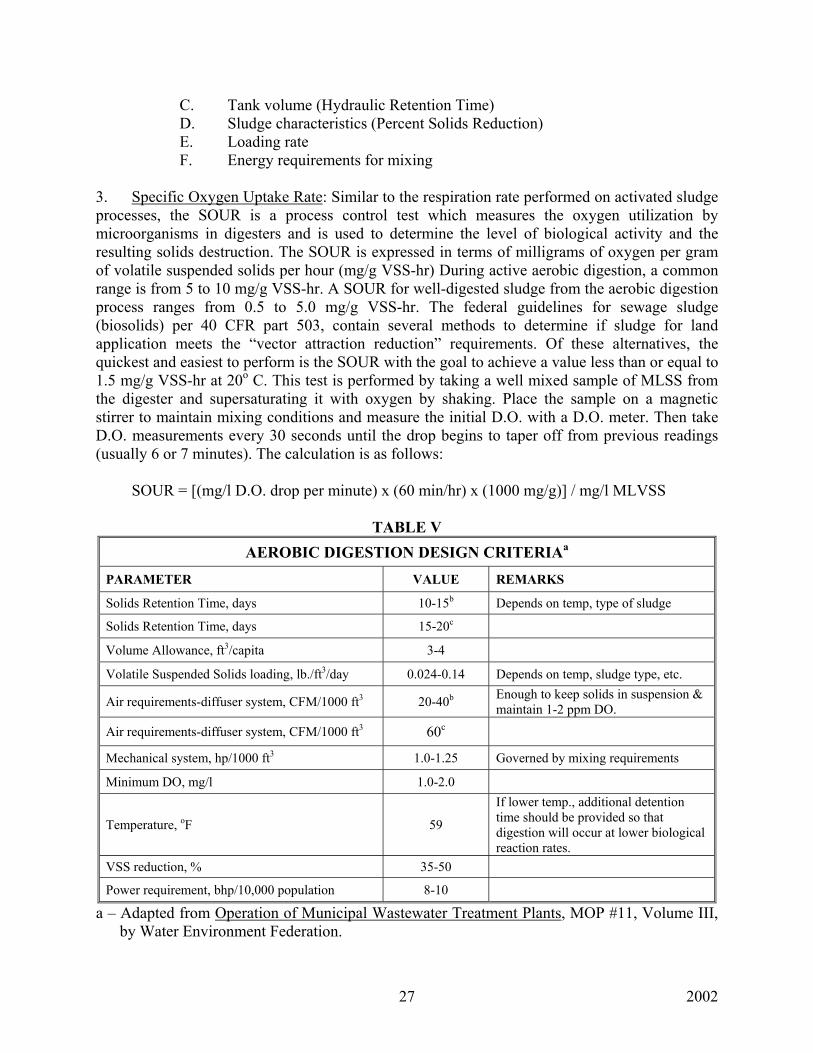
C. Tank volume (Hydraulic Retention Time) D. Sludge characteristics (Percent Solids Reduction) E. Loading rate F. Energy requirements for mixing 3. Specific Oxygen Uptake Rate: Similar to the respiration rate performed on activated sludge processes, the SOUR is a process control test which measures the oxygen utilization by microorganisms in digesters and is used to determine the level of biological activity and the resulting solids destruction. The SOUR is expressed in terms of milligrams of oxygen per gram of volatile suspended solids per hour (mg/g VSS-hr) During active aerobic digestion, a common range is from 5 to 10 mg/g VSS-hr. A SOUR for well-digested sludge from the aerobic digestion process ranges from 0.5 to 5.0 mg/g VSS-hr. The federal guidelines for sewage sludge (biosolids) per 40 CFR part 503, contain several methods to determine if sludge for land application meets the “vector attraction reduction” requirements. Of these alternatives, the quickest and easiest to perform is the SOUR with the goal to achieve a value less than or equal to 1.5 mg/g VSS-hr at 20o C. This test is performed by taking a well mixed sample of MLSS from the digester and supersaturating it with oxygen by shaking. Place the sample on a magnetic stirrer to maintain mixing conditions and measure the initial D.O. with a D.O. meter. Then take D.O. measurements every 30 seconds until the drop begins to taper off from previous readings (usually 6 or 7 minutes). The calculation is as follows: SOUR = [(mg/l D.O. drop per minute) x (60 min/hr) x (1000 mg/g)] / mg/l MLVSS
TABLE V AEROBIC DIGESTION DESIGN CRITERIAa
PARAMETER VALUE REMARKS
Solids Retention Time, days 10-15b Depends on temp, type of sludge
Solids Retention Time, days 15-20c
Volume Allowance, ft3/capita 3-4
Volatile Suspended Solids loading, lb./ft3/day 0.024-0.14 Depends on temp, sludge type, etc.
Air requirements-diffuser system, CFM/1000 ft3 20-40b Enough to keep solids in suspension & maintain 1-2 ppm DO.
Air requirements-diffuser system, CFM/1000 ft3 60c
Mechanical system, hp/1000 ft3 1.0-1.25 Governed by mixing requirements
Minimum DO, mg/l 1.0-2.0
Temperature, oF 59
If lower temp., additional detention time should be provided so that digestion will occur at lower biological reaction rates.
VSS reduction, % 35-50
Power requirement, bhp/10,000 population 8-10
a – Adapted from Operation of Municipal Wastewater Treatment Plants, MOP #11, Volume III, by Water Environment Federation.
2002 28
b – Excess activated sludge alone. c – Primary & excess activated sludge or primary sludge alone.
ANAEROBIC DIGESTION
1. Anaerobic digestion is a complex biological process involving several groups of anaerobic and facultative organisms simultaneously breaking down and assimilating organic matter in the absence of oxygen. For simplicity, it can be considered to be a three-stage process. During the first stage, complex organic materials hydrolyze into simpler compounds. In the second stage, saprophytic organisms commonly referred to as “acid formers” convert these organic compounds into volatile organic acids. In the third stage, the “methane fermenters” convert the acids into methane and carbon dioxide. Since the methane fermenters are not as abundant in raw wastewater as are the acid formers and are more easily stressed, care must be taken to operate an anaerobic digester so that the rate of acid formation and methane formation are approximately equal; otherwise the reaction will get out of balance. The methane formers function best at a pH range of 6.6 to 7.6 and will only reproduce in that range. Typical operating pH ranges are from 6.8 to 7.2. In most cases, the methane forming bacteria control the process. They are very sensitive to environmental factors and reproduce very slowly. Process design and operation, therefore, are tailored to satisfy the needs of the methane forming bacteria. Factors affecting digester performance include detention time, temperature, solids concentration, degree of mixing, solids loading, pH, alkalinity, volatile acid content, nutrients, and toxic materials.[2]
2. Process description: The two most common types of digesters are identified as standard-rate and high-rate. In the standard-rate digester, the contents are usually unheated and unmixed with detention times varying from 30 to 60 days. In the high-rate digestion process, the contents are heated and completely mixed with detention times typically 15 days or less. A combination of these two basic processes is known as the “two-stage process” where the primary function of the second stage is to separate the digested solids from the supernatant liquor, although additional digestion and gas production may occur.[1] Digesters are normally operated in one of three temperature ranges. The lowest range for unheated digesters is the psychrophilic zone. Organisms in this range tend to adjust to the outside temperature, however, below 50oF little or no bacterial activity occurs and the necessary reduction in sludge volatility will not occur. Few digesters today are designed to operate in this range, but there are still some in operation such as the Imhoff tank. The second range and the one most commonly used is the mesophilic zone for temperatures ranging from 68oF to 113oF. Optimum ranges are from 85oF to 100oF with most being operated at 95oF. It is important to maintain a constant temperature and not let it vary more than one degree each day. At temperatures above 113oF, digesters are operating in the thermophilic zone. Optimum temperature ranges are 120-135oF. Few digesters are operated in this range due to problems of maintaining temperature, sensitivity of the organisms to temperature change, and some reported problems of poor solids-liquid separation.[4]
2002 29
Digester covers may be of either the fixed type or floating type. With the fixed cover, care must be taken to prevent air from being drawn into the tank when sludge is withdrawn otherwise an explosive mixture can result. When starting up a digester, first check water, gas, and sludge lines for leaks; then fill the tank with water or wastewater to seal the cover. Bring the contents up to temperature and being mixing before ever adding raw sludge to lesson the possibility of an explosive mixture of gases being formed. The explosive range of the main product of anaerobic digestion, methane, is in the range of 5-15%. If too much raw sludge is added to a digester, the acid fermenters will predominate, driving the pH down and creating an undesirable condition for the methane fermenters. The digester will go sour or acid. When a digester recovers from a sour condition, the breakdown of the volatile acids and formation of methane and carbon dioxide is usually very rapid. The digester may then foam or froth, forcing sludge solids through water seals and gas lines and causing a fairly serious operational problem. A sour digester usually requires 30 to 60 days to recover.[4]
4. Gas production: Gas produced from anaerobic digesters normally contains by volume 65-70% methane (CH4), 25-30% carbon dioxide (CO2), and small amounts of N2, H2, hydrogen sulfide (H2S), water vapor, and other gases. Typical volumes of methane produced vary from 12 to 18 ft3 per pound of volatile solids destroyed. The low heating value of the digester gas at 65% methane is approximately 600 BTU/ft3. By comparison, natural gas has a low heating value of approximately 1000 BTU/ft3.[1] 5. Volatile Acid/Alkalinity relationship: Monitoring this ratio is the key to successful digester performance. As long as the volatile acids remain low and the alkalinity stays high (example: 120 mg/l volatile acids/2400 mg/l alkalinity) anaerobic digestion will occur. When the ratio starts to increase, corrective action must be taken immediately to prevent the increase in CO2 production with a resultant pH drop and eventual soured digester. The ratio should be checked at least twice weekly and trend charts maintained. Possible causes for the ratio to get out of balance include sudden temperature drops, excessive feeding of raw sludge, excessive removal of digested sludge, or toxic overloads. Generally, the pounds of volatile solids in the feed sludge should not exceed 5% of the total pounds of volatile solids in the digester. When digestion is proceeding satisfactorily, the alkalinity will normally range from 1000 to 5000 mg/l, and the volatile acids will be less than 250 mg/l. The volatile acid/alkalinity ratio must be maintained at less than 0.25. Generally, this ratio for a healthy digester will be 0.1 or less. Once the ratio reaches 0.3 – 0.4 the digester is being stressed and a definite problem is developing. Once the relationship reaches the vicinity of 0.5, serious decreases in the alkalinity usually occur and the concentration of CO2 in digester gas will start increasing. When the ratio reaches 0.8 or higher, the pH will begin to drop. However, since the pH depression does not occur until the alkalinity is depleted, digester failure has already occurred by the time the pH drop may have been detected. SLUDGE HANDLING & DISPOSAL 1. It is usually more economical to dewater sludge prior to disposal rather than pumping or hauling liquid sludge to disposal sites. The primary objective of dewatering is to reduce sludge moisture and consequently sludge volume. Processes most commonly used for dewatering are as follows:
2002 30
A. Pressure filtration: There are two types of pressure filtration systems used, (1) plate and frame filter presses, and (2) belt filter press. The plate and frame filter press operates in a batch manner and consists of vertical plates which are held rigidly in a frame and pressed together. Sludge is fed into the press through feed holes along the length of the press. As filtration proceeds, water filtrate passes through the fibers of the cloth mounted on the face of each plate and is collected in drainage ports provided at the bottom of each press chamber and then discharged. As the cake builds up and the resistance increases, the volume of filtrate decreases. When the filtrate flow is near zero, the feed is shut off and the plates are disengaged, and the retained cakes fall by gravity into a hopper or conveyor. The solids removal efficiency is affected by sludge type, conditioning, filter pressure, filtration time, solids loading, filter cloth type, and pre-coat material used such as diatomaceous earth. Materials used to condition sludge prior to filtration generally are lime or ferric chloride. Generally, the initial pressure is maintained at approximately 25 psi for 5 to 10 minutes then increased at intervals approximating 5 psi/min until the terminal operating pressure is reach which can vary usually from 100 to 225 psi. Belt filter presses operate in a continuous manner and consist of two endless belts that travel over a series of rollers. Sludge is preconditioned usually with polymers and then applied to the free-water drainage zone of the filter belt. The partially dewatered solids are carried to a point on the unit where they are trapped between two endless belts and further dewatered as they travel over a series of perforated and imperforated rollers. This zone is known as the “press” or “dewatering zone.” Water is forced from between the belts and collected in filtrate trays while the retained solids are scraped from the two belts when they separate at the discharge end of the press. The two endless belts then travel through respective washing chambers for the removal of fine solids to decrease the possibility of plugging. Factors affecting belt pressure filtration include sludge type, conditioning, belt tension or pressure, belt speed, hydraulic loading, and belt type. Unlike plate and frame filter presses, the belt filter might not be able to handle secondary or waste activated sludge’s consistently because these sludge’s lack fibrous materials and exhibit a plastic or jello-like nature. If this problem is apparent, primary sludge may have to be blended with the secondary sludge to add fibrous material. With the addition of polymers, this blending has produced sludge cakes in the range of 24 to 26%. Belt speeds generally vary between 2 to 10 feet/minute with belt widths ranging from 1.5 to 7 feet. Loadings are from 10 to 25 gpm per foot of width.[5] B. Vacuum filtration: These filters consist of a rotating drum which continuously passes through a trough or pan containing the sludge to be dewatered. The cloth media is submerged about 20 to 40% in the trough, and the trough is equipped with an agitator to keep the chemically conditioned sludge well mixed and from settling in the trough. The filter drum is divided into compartments and a vacuum applied to each compartment in the range of 15 to 30 inches of mercury. With the vacuum, sludge is picked up on the submerged compartment and sludge mat formed. As the drum rotates out of the trough, the vacuum is decreased slightly and water is sucked from the sludge mat, through the filter media and discharged through internal pipes to a drainage system. The dewatered solids remaining on the filter media are then discharged to a sludge hopper or conveyor via scrapers or discharge rollers. Factors affecting vacuum filtration include sludge type, conditioning, applied vacuum, drum speed or cycle time, depth of submergence, and media type and condition. Generally, secondary sludges are not easily
2002 31
dewatered by vacuum filtration even after conditioning with lime or ferric chloride. Thermally conditioned sludges or sludges blended with primary sludge are required for successful dewatering with vacuum filtration. The test used to determine the effective chemical dosage for the best dewatering results is called the “Buckner Funnel Test.”[5]
C. Centrifugation: Centrifugal sludge dewatering results from sedimentation and high centrifugal forces. Sludge is fed to a rotating bowl, and solids are separated from the liquid phase by the centrifugal forces and are forced to the bowl wall and compacted. Two basic designs include the batch operated basket centrifuge and continuous flow scroll centrifuges. D. Sand drying beds: Primarily used at smaller to medium sized treatment plants, drying beds usually contain 6 to 9 inches of sand placed over 12 to 20 inches of graded gravel or stone. Sludge is placed on the beds normally to a depth of 8 to 12 inches which will result in dewatered sludge ready for removal in three to four weeks during the warm weather months. This process can be speeded up with the addition to polymers. Factors affecting drying bed performance include sludge type, conditioning, climatic conditions, sludge application rates and depths, and dewatered sludge removal techniques. Fresh sludge should never be applied to a bed already containing partially dried sludge since unhindered filtrate drainage will be impaired. Sludge should be digested to a volatile content of 45-60% for improved dewatering. Drying bed area is normally in the range of 2 ft2 per capita. One problem with sludges containing polymers is that the water held by the polymer may be released during the transportation to the disposal site. Landfill disposed sludges must (1) pass the paint filter test, (2) pass the Toxicity Characteristics Leaching Procedure (TCLP) test, and (3) be adequately digested.
PUMPS & MOTORS 1. Categories of pumps:
A. They may be classified by the character of the material handled – raw wastewater, grit, effluent, activated sludge, raw sludge, or digested sludge.
B. They may be classified by pumping conditions – high lift, low lift, recirculation, or high
capacity. C. They may be classified by the principle of operation – centrifugal, propeller,
reciprocating, incline screw, progressive cavity, or pneumatic ejector.
2. Centrifugal pumps: These pumps have an impeller (paddle-wheel type piece) rotating in a casing. The impeller is supported on a shaft which is then supported by bearings. Liquid enters the casing through the eye (at the center) of the impeller. It is then picked up by the curved impeller vanes and by the rotation of the impeller and is thrown out by the centrifugal force into the discharge. Impellers usually have large openings at their center to prevent clogging. A screen should be used at the intake end of the suction piping to prevent clogging. Impellers may be in closed casings or they may be open if the pump is submersible and being used to pump wastewater from lift station wet wells. The motor or drive mechanism can be connected directly to the shaft or connected by a coupling flange depending upon the application.
2002 32
A. Shaft sleeves are used to cover the shaft that supports the impeller to protect the shaft
from the corrosive and abrasive effects of the liquid going through the pump. The sleeves are mounted to the shaft on ball or roller bearings.
B. Wearing rings are used to plug the space between the impeller and the casing to prevent
internal liquid leakage. These rings are either attached to the casing, the impeller, or both. Wearing rings should be inspected regularly and replaced when serious wear or leakage is observed. Since water is the lubricant between the rings and the impeller, a pump should never be allowed to run dry.
C. Stuffing boxes are used to prevent air from being sucked into the pump. Air affects the
efficiency of the pump and could cause it to lose prime. It consists of a casing containing rings of packing and a gland or membrane at the outside end. Water is used in the stuffing box to block out the intake of air and to lubricate the packing. The water is brought into a seal cage in the center of the stuffing box under pressure by connector piping to a point near the impeller rim provided it is clean liquid. If the liquid being pumped contains grit or other solids, it may be necessary to use potable water to provide the seal. To prevent the possibility of a cross-connection, the connection with the potable water supply must include either an air gap separation or an approved backflow preventer. The end gland or membrane is used to control liquid flow from the stuffing box. The gland should be tightened just enough such that a thin stream of water flows from the stuffing box. Excessive leakage is indicative of the need to replace the packing.
D. Lantern rings provide the water seal connection between the water supply line and the
stuffing box. When packing is being replaced, the lantern ring should be completely filled with grease (if grease seals are used) before all the rings of packing are in place.
E. The efficiency of centrifugal non-clog pumps starts at zero at shut-off and increases
rapidly until a peak is reached at approximately the mid-point of the overall capacity range of the pump. Therefore, for peak efficiency, best mechanical performance, and quietest operation; a pump should be selected so that the range of operation will be at the mid-point of the total pump curve. They should be operated near their rated heads (pressure). Otherwise, the pump is apt to operate under unsatisfactory and unstable conditions which reduce the efficiency and operating life of the unit.
3. Propeller pumps: Two basic types. A. Axial-flow pumps have flow parallel to the axis of the impeller. B. Mixed-flow pumps have flow that is both axial and radial (perpendicular to the shaft) to
the impeller. 4. Reciprocating or Piston pumps: Pumps used to move sludge by a piston that moves back
and forth. Reciprocating pumps should never be allowed to pump against a closed
2002 33
discharge valve due to a build up of pressure that could damage the pump and/or the piping.
5. Incline screw pumps: An auger type pump housed in a trough that is on an incline. The
auger is supported by bearings on both ends. The screw or auger operates at a constant speed moving the wastewater up the trough to a point of discharge. These are commonly used on influent and effluent waste streams where low lift, high capacity, non-clog pumping is required. They may range in size from 12 to 144 inches in diameter with rated capacities from 100 to 70,000 gpm. They are primarily suited for lifts up to 25 feet but are available for higher lifts.
6. Progressive cavity pumps: These are similar to incline screw pumps except that the screw
shaped rotor is enclosed in a housing (stator). The spacing between the rotor and the inside casing walls form a series of cavities. As the rotor turns, the threads make contact with the walls and move the water along in auger fashion. The size of the cavities along the rotor determines the capacity of the pump. These pumps are recommended for liquids containing higher concentrations of solids. Like reciprocating pumps, they should never be operated dry nor against a closed discharge valve.
7. Pneumatic ejectors (Air Lift): An air lift ejector consists of a receiving container, inlet and
outlet check valve, air supply, and liquid level detector. When the wastewater reaches a preset level, air is forced into the container, ejecting the wastewater. Following the discharge cycle, the air supply is cut off and wastewater flows through the inlet into the receiver. With flow ranges from 30 to 150 gpm, they are mostly used for pumping raw wastewater. These pumps are capable of passing solids up to the size of the inlet and discharge valves since there is nothing on the inside of the ejector-receiver to restrict the flow. They are, however, a high maintenance problem. If a stick or other object gets stuck in either check valve, the ejector will not operate.
8. Maintenance of pump motors: A. Check the condition of the motor for dirt, dust, moisture, air circulation obstructions,
and excessive leakage of grease from the bearings. B. Observe any unusual conditions including noise, excessive heat, vibration, intermittent
to continuous sparking of brushes, or sluggish operation. A stethoscope is sometimes used to check for bearing whines, gratings, or uneven noises.
C. Keep close watch on the amperage being pulled by the motors. A sudden increase could
be indicative of a pumping restriction while a sudden decrease may be the result of a drop in pumping head caused by a break in the discharge line.
D. For motors wound for 3-phase current, periodically check to insure equal distribution
across all three phases. If one phase cuts out while in operation the motor may overheat and become damaged unless it is stopped by a thermal control device.
2002 34
9. Pump Operating Problems & Causes of Failure or Reduced Operating Efficiency: A. Causes for pump not starting:
(1.) Blown fuses or circuit breakers due to: (a) Rating of fuses or circuit breakers not correct, (b) Switch (breaker) contacts corroded or shorted, (c) Terminal connections loose or broken somewhere in the circuit, (d) Automatic control mechanism not functioning properly, (e) Motor shorted or burned out, (f) Wiring hookup or service not correct, (g) Switches not set for operation, (h) Contacts of the control relays dirty and arcing, (i) Fuses or thermal units too warm, (j) Wiring short-circuited, (k) Shaft binding or sticking due to rubbing impeller, tight packing glands, or clogging of pump
(2.) Loose connection, fuse, or thermal unit. B. Causes for reduced pump discharge rates: (1) Pump not primed (2) Mixture of air in the wastewater (3) Speed of motor too
low (4) Improper wiring (5) Defective motor (6) Discharge head too high (7) Suction lift higher than anticipated (8) Impeller clogged (9) Discharge line clogged (10) Pump rotating in wrong direction (11) Air leaks in suction line or packing box (12) Inlet to suction too high, permitting air to enter (13) Valves partially or entirely closed (14) Check valves stuck or clogged (15) Incorrect impeller adjustment (16) Impeller damaged or worn (17) Packing worn or defective (18) Impeller turning on shaft because of broken key (19) Flexible coupling broken (20) Loss of suction during pumping may be caused by leaky suction line, ineffective water or grease seal. (21) Belts slipping (22) Worn wearing ring.
C. Causes for high power requirements: (1) Speed of rotation too high (2) Operating heads lower than rating for which
pump was designed, resulting in excess pumping rates (3) Check valves open, draining long force-main back into wet-wall (4) Specific gravity or viscosity of liquid pumped too high (5) Clogged pump (6) Sheaves on belt drive misaligned or maladjusted (7) Pump shaft bent (8) Rotating elements binding (9) Packing too tight (10) Wearing rings worn or binding (11) Impeller rubbing.
D. Causes for noisy pump operation: (1) Pump not completely primed (2) Inlet clogged (3) Inlet not submerged (4) Pump
not lubricated properly (5) Worn impellers (6) Strain on pumps caused by unsupported piping fastened to the pump (7) Foundation insecure (8) Mechanical defects in pump (9) Misalignment of motor and pump where connected by flexible shaft (10) Rags or sticks bound (wrapped) around impeller.
2002 35
INDUSTRIAL WASTEWATER TREATMENT 1. Dairy Wastes: Wastes from milk-product installations including bottling plants, cheese
factories, and ice cream plants. Waste is high strength in BOD5 and TSS with BOD5 ranging from 1000 to 10,000 ppm. Normal treatment is flow equalization, pretreatment by chemical precipitation, and biological treatment. Nutrient addition may be required for biological processes.
2. Tannery Wastes: Wastes from the manufacture of leather from animal hides. Waste is high
strength in salt, BOD5 (~1000 ppm), & TSS (~8000 ppm). Normal treatment is pre-screening followed by biological treatment.
3. Pulp & Paper Wastes: Wastes are produced from the recovery of fiber from wood or other
vegetable matter for subsequent processing into paper. BOD5 ranges from 200 to 1000 ppm. Normal treatment is primary settling followed by stabilization ponds, chemical precipitation or activated sludge. Nutrient addition may be required.
4. Meat Packing Wastes: Wastes produced from stockyards, slaughter houses, and packing
houses. Stockyard wastes (manure, straw, etc.) are suitable for land disposal. Slaughter and packing house waste is extremely high strength with BOD5 up to 400,000 ppm. Average water use is from 1000 to 5000 gallons per 1000 pounds of live weight killed. Normal treatment includes pretreatment to include flow equalization, screening, and grease and solids separation by gravity and/or dissolved air flotation, and aerobic or anaerobic biological treatment.
5. Fermentation Wastes: Wastes produced from the breaking down of sugars and starches into
simpler compounds by yeasts (beer, wine, alcohol, and penicillin). Unfermented raw materials are recovered as insoluble solids and used as animal feed and the production of certain chemicals. Water use in the brewery industry is generally 10 to 15 gallons per gallon of beer produced. Strength of wastes varies from brewery BOD5 = 500 to 1000 ppm to antibiotic BOD5 = 20,000 ppm. Normal treatment is biological (trickling filters & anaerobic digesters). Nutrient addition may be required.
6. Fruit & Vegetable Processing Wastes: Wastes from preliminary cleaning, blanching,
canning, and juicing. Wastes can be highly variable in strength. Normal treatment includes screening, grit removal for root crops, sedimentation for potato, tomato, and carrot process wastewater. Biological treatment can be effective if nutrient deficiency and seasonal loading problems can be overcome.
2002 36
7. Textile Wastes: Wastes produced from the manufacture of woven fabrics from either natural (wool, cotton, silk) or synthetic (rayon, acrylics, polyester) fibers. The primary wastes from natural fibers are dirt, grease, and waxes. The main synthetic wastes are the chemicals used in the processing. For every 1000 pounds of wool sheared, 400 pounds of finished wool is produced and the rest is waste. Normal treatment includes flow equalization, pH adjustment, screening, chemical treatment for removal of metals or coagulation for removal of detergents, and subsequent biological treatment.
8. Petroleum Wastes: Wastes produced from the production or refining of oil. Brine is the main waste produced and is normally disposed by injection. It may also be treated by solar evaporation, dilution, or chemical coagulation. Normal treatment includes oil & water separation, chemical coagulation, sedimentation, and biological treatment.
9. Metal Finishing Wastes: Wastes produced from the cleaning, hardening, softening,
roughing, smoothing, coating, and plating of various metals. Metals most commonly plated are copper, cadmium, nickel, zinc, and chromium. Toxic materials produced are acids, chromium, zinc, copper, nickel, tin, and cyanide.
A. The EPA has identified six pollutants which are potentially of concern to all POTWs
because of their widespread occurrence. They are referred to as “priority pollutants” and are as follows: cadmium, chromium, copper, lead, nickel, and zinc. Four additional pollutants presumed to be of concern unless initial testing shows that they are not present are arsenic, cyanide, silver, and mercury.
B. Normal treatment is by chemical addition due to high toxicity to biological treatment
systems. The solubility of most metals of concern is directly affected by pH. By adjusting the pH to the point of least solubility for the metal, it can be precipitated out.
C. Cyanide wastes are normally treated using alkaline chlorination due to the release of
highly toxic HCN gas at low pH values. D. Metals are classified as conservative pollutants since they are not degraded or
volatilized during the normal treatment process. Non-conservative pollutants such as organics and cyanide are biodegraded and volatilized during the treatment process. Losses through biodegradation do not contribute to pollutant loadings in sludge, whereas losses of metals will be transferred entirely to the sludge.
ACTIVATED CARBON ADSORPTION
ABSORPTION – Taking in or soaking up of one substance into the body of another by molecular or chemical action (tree roots absorb dissolved nutrients in the soil). ADSORPTION – The attraction and accumulation of a gas, liquid, or dissolved substance on the surface or interface zone of another substance (similar to a magnet). 1. Activated carbon adsorption is used to provide tertiary treatment to treatment plant effluents primarily to remove organics such as PCBs, phenols, and solvents. Removal of the
2002 37
organic pollutants reduces color, taste, and odor problems that may still remain in the effluent after conventional treatment. 2. Activated carbon is produced from wood, coal, nutshells, bone, petroleum residues, or sawdust. It is activated by drying the raw material and slowly heating it in the absence of air. 3. Detention times are typically 15-35 minutes. 4. Carbon column reactors are usually 8-15 feet in diameter and 15 to 28 feet tall. Reactors are lined with epoxy or resin to prevent contact of the corrosive wet carbon with steel walls. 5. Carbon regeneration includes heat treatment in a multiple hearth furnace or rotary kiln at temperatures up to 1750o Fahrenheit (90-95% recovery). Steam is added for cleansing the carbon of absorbed material. 6. Removal efficiencies of organics are measured by COD & turbidity results on a routine basis. 7. Typical loading rates: Hydraulic = 2 to 10 gal/min/ft2. Organic = 0.5 lbs. COD/day/lb. of carbon 8. TSS concentrations of 20 mg/l or higher from secondary effluents will deposit on the carbon granules as a floc resulting in high pressure loss and blockage of flow. Similarly, variations in pH, temperature, and flow rate may adversely affect carbon adsorption.
Related Documents

![Eisberg R & Resnick R - Quantum Physics - Atoms, Molecules, Solids, Nuclei, And Particles - Solutions Supplement Accompany (2Ed Wiley)[1]](https://static.cupdf.com/doc/110x72/5572071b497959fc0b8ba297/eisberg-r-resnick-r-quantum-physics-atoms-molecules-solids-nuclei-and-particles-solutions-supplement-accompany-2ed-wiley1.jpg)