Annex to ED Decision 2019/012/R Certification Specifications and Guidance Material for the design of surface-level VFR heliports located at aerodromes that fall under the scope of Regulation (EU) 2018/1139 (CS-HPT-DSN) Issue 1 23 May 2019 1 1 For the date of entry into force of this issue, kindly refer to Decision 2019/012/R in the Official Publication of the Agency.

Welcome message from author
This document is posted to help you gain knowledge. Please leave a comment to let me know what you think about it! Share it to your friends and learn new things together.
Transcript
Annex to ED Decision 2019/012/R
Certification Specifications and
Guidance Material
for the design of surface-level
VFR heliports located at aerodromes that fall under the scope of Regulation (EU) 2018/1139
(CS-HPT-DSN)
Issue 1
23 May 20191
1 For the date of entry into force of this issue, kindly refer to Decision 2019/012/R in the Official Publication of the Agency.
CS-HPT-DSN Table of contents
Annex to ED Decision 2019/012/R Page 2 of 53
TABLE OF CONTENTS
Table of contents ........................................................................... 2
CS-HPT-DSN ................................................................................... 5
List of abbreviations ................................................................................................. 5
CHAPTER A — GENERAL ......................................................................... 6
CS HPT-DSN.A.010 Applicability........................................................................................ 6 GM1 HPT-DSN.A.010 Applicability ......................................................................... 6
CS HPT-DSN.A.020 Definitions .......................................................................................... 6 GM1 HPT-DSN.A.020 Definitions ............................................................................ 7
CHAPTER B — HELICOPTER OPERATING AREAS ...................................... 8
CS HPT-DSN.B.100 Final approach and take-off areas (FATOs) ........................................ 8 GM1 HPT-DSN.B.100 Final approach and take-off areas (FATOs).......................... 9
CS HPT-DSN.B.110 Helicopter clearways .......................................................................... 9 GM1 HPT-DSN.B.110 Helicopter clearways ......................................................... 10
CS HPT-DSN.B.120 Touchdown and lift-off areas (TLOFs) .............................................. 10 GM1 HPT-DSN.B.120 Touchdown and lift-off areas (TLOFs) ................................ 10
CS HPT-DSN.B.130 Safety areas ...................................................................................... 10 GM1 HPT-DSN.B.130 Safety areas........................................................................ 11
CHAPTER C — HELICOPTER TAXIWAYS AND TAXI-ROUTES .................... 12
CS HPT-DSN.C.200 Helicopter ground taxiways and helicopter ground taxi-routes ...... 12 GM1 HPT-DSN.C.200 Helicopter ground taxiways and helicopter ground taxi-routes ..................................................................................................................... 13
CS HPT-DSN.C.210 Helicopter air taxiways and helicopter air taxi-routes ..................... 13 GM1 HPT-DSN.C.210 Helicopter air taxiways and helicopter air taxi-routes ...... 15
CHAPTER D — HELICOPTER STANDS ..................................................... 16
CS HPT-DSN.D.300 Helicopter stands ............................................................................. 16 GM1 HPT-DSN.D.300 Helicopter stands ............................................................... 18
CHAPTER E — OBSTACLE LIMITATION SURFACES AND REQUIREMENTS 20
CS HPT-DSN.E.400 Applicability ...................................................................................... 20 GM1 HPT-DSN.E.400 Applicability ........................................................................ 20
CS HPT-DSN.E.410 Approach surface ............................................................................. 20 GM1 HPT-DSN.E.410 Approach surface ............................................................... 25
CS HPT-DSN.E.420 Take-off climb surface ...................................................................... 26 GM1 HPT-DSN.E.420 Take-off climb surface ........................................................ 26
CS-HPT-DSN Table of contents
Annex to ED Decision 2019/012/R Page 3 of 53
CS HPT-DSN.E.430 Obstacle limitation requirements .................................................... 27 GM1 HPT-DSN.E.430 Obstacle limitation requirements ...................................... 27
CHAPTER F — VISUAL AIDS ................................................................... 28
CS HPT-DSN.F.500 General ............................................................................................. 28 GM1 HPT-DSN.F.500 General ............................................................................... 28
CS HPT-DSN.F.510 Wind direction indicators ................................................................. 28 GM1 HPT-DSN.F.510 Wind direction indicators ................................................... 28
CS HPT-DSN.F.520 Heliport identification marking ........................................................ 29 GM1 HPT-DSN.F.520 Heliport identification marking .......................................... 31
CS HPT-DSN.F.530 Final approach and take-off area perimeter marking or markers.... 31 GM1 HPT-DSN.F.530 Final approach and take-off area perimeter marking or markers .................................................................................................................. 32
CS HPT-DSN.F.540 Final approach and take-off area designation marking ................... 32 GM1 HPT-DSN.F.540 Final approach and take-off area designation marking ..... 33
CS HPT-DSN.F.550 Aiming point marking ....................................................................... 33 GM1 HPT-DSN.F.550 Aiming point marking ......................................................... 34
CS HPT-DSN.F.560 Touchdown and lift-off area perimeter marking ............................. 34 GM1 HPT-DSN.F.560 Touchdown and lift-off area perimeter marking ............... 34
CS HPT-DSN.F.570 Touchdown/positioning marking ..................................................... 34 GM1 HPT-DSN.F.570 Touchdown/positioning marking ....................................... 35
CS HPT-DSN.F.580 Heliport name marking..................................................................... 35 GM1 HPT-DSN.F.580 Heliport name marking ...................................................... 35
CS HPT-DSN.F.590 Helicopter ground taxiway markings and markers .......................... 35 GM1 HPT-DSN.F.590 Helicopter ground taxiway markings and markers ............ 36
CS HPT-DSN.F.600 Helicopter air taxiway markings and markers .................................. 36 GM1 HPT-DSN.F.600 Helicopter air taxiway markings and markers ................... 37
CS HPT-DSN.F.610 Helicopter stand markings ............................................................... 38 GM1 HPT-DSN.F.610 Helicopter stand markings ................................................. 40
CS HPT-DSN.F.620 Flight path alignment guidance marking .......................................... 40 GM1 HPT-DSN.F.620 Flight path alignment guidance marking ........................... 41
CS HPT-DSN.F.630 Approach lighting system ................................................................. 41 GM1 HPT-DSN.F.630 Approach lighting system ................................................... 42
CS HPT-DSN.F.640 Flight path alignment guidance lighting system ............................... 42 GM1 HPT-DSN.F.640 Flight path alignment guidance lighting system ................ 43
CS HPT-DSN.F.650 Visual alignment guidance system ................................................... 43 GM1 HPT-DSN.F.650 Visual alignment guidance system ..................................... 46
CS HPT-DSN.F.660 Visual approach slope indicator ....................................................... 47 GM1 HPT-DSN.F.660 Visual approach slope indicator ......................................... 49
CS HPT-DSN.F.670 Final approach and take-off area lighting systems .......................... 49 GM1 HPT-DSN.F.670 Final approach and take-off area lighting systems ............ 50

CS-HPT-DSN Table of contents
Annex to ED Decision 2019/012/R Page 4 of 53
CS HPT-DSN.F.680 Aiming point lights ............................................................................ 50 GM1 HPT-DSN.F.680 Aiming point lights ............................................................. 51
CS HPT-DSN.F.690 Touchdown and lift-off area lighting system ................................... 51 GM1 HPT-DSN.F.690 Touchdown and lift-off area lighting system ..................... 52
CS HPT-DSN.F.700 Taxiway lights ................................................................................... 52 GM1 HPT-DSN.F.700 Taxiway lights ..................................................................... 52
CS HPT-DSN.F.710 Visual aids for denoting obstacles .................................................... 53 GM1 HPT-DSN.F.710 Visual aids for denoting obstacles ...................................... 53
CS-HPT-DSN List of abbreviations
Annex to ED Decision 2019/012/R Page 5 of 53
CS-HPT-DSN
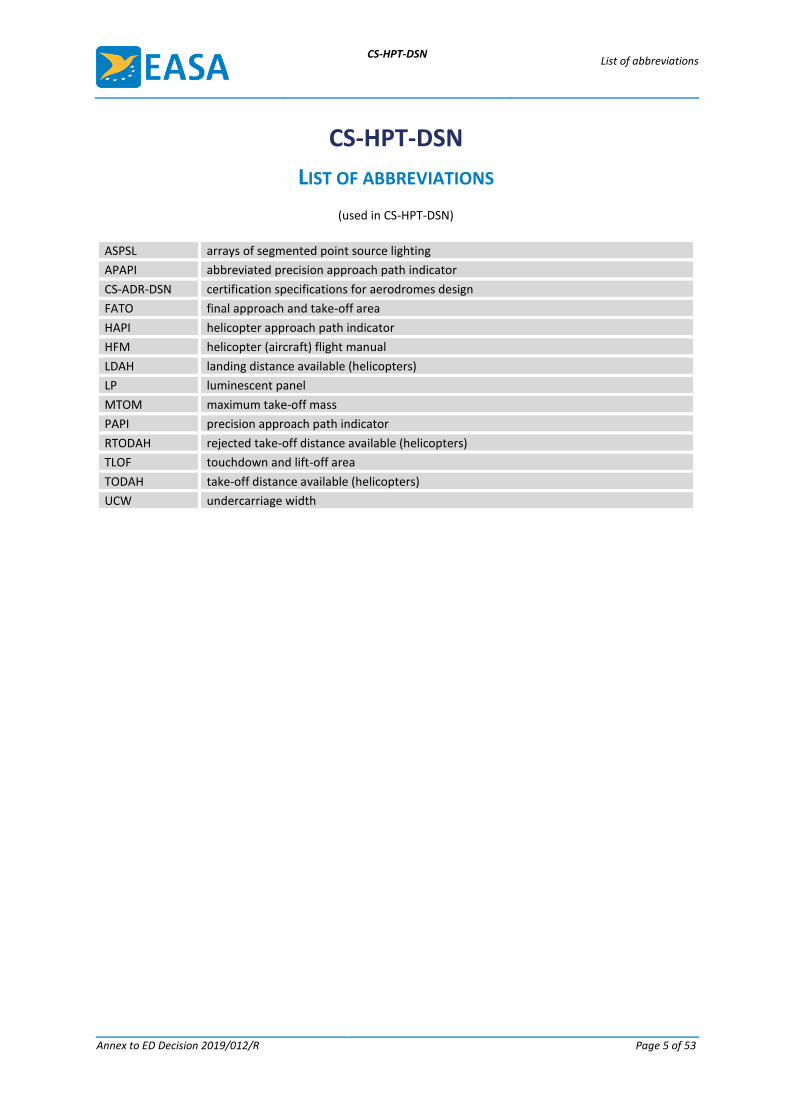
LIST OF ABBREVIATIONS
(used in CS-HPT-DSN)
ASPSL arrays of segmented point source lighting
APAPI abbreviated precision approach path indicator
CS-ADR-DSN certification specifications for aerodromes design
FATO final approach and take-off area
HAPI helicopter approach path indicator
HFM helicopter (aircraft) flight manual
LDAH landing distance available (helicopters)
LP luminescent panel
MTOM maximum take-off mass
PAPI precision approach path indicator
RTODAH rejected take-off distance available (helicopters)
TLOF touchdown and lift-off area
TODAH take-off distance available (helicopters)
UCW undercarriage width
CS-HPT-DSN CHAPTER A — GENERAL
Annex to ED Decision 2019/012/R Page 6 of 53
CHAPTER A — GENERAL
CS HPT-DSN.A.010 Applicability
(a) The certification specifications (CSs) and the related guidance material (GM) (CS-HPT-DSN) are applicable to the design of surface-level VFR heliports or parts thereof located at aerodromes that fall under the scope of Regulation (EU) 2018/1139.
(b) Where relevant, the CSs and GM for aerodrome design (CS-ADR-DSN) apply to the aerodrome areas and infrastructure used by helicopters.
(c) Unless otherwise specified, the specifications for a colour referred to within CS-HPT-DSN should be those contained in CS-ADR-DSN.
GM1 HPT-DSN.A.010 Applicability
The CSs and the related GM are applicable to the design of surface-level VFR heliports, including those that are not open for public use or for commercial air transport, which are located at aerodromes that fall under the scope of Regulation (EU) 2018/1139.
CS HPT-DSN.A.020 Definitions
For the purposes of CS-HPT-DSN, the following definitions should apply:
‘D’ means the largest overall dimension of the helicopter when rotor(s) are turning measured from the most forward position of the main rotor tip path plane to the most rearward position of the tail rotor tip path plane or helicopter structure.
Note: ‘D’ is sometimes referred to in the text using the term ‘D-value’.
‘Declared distances’ — heliports means:
— Take-off distance available (TODAH). The length of the FATO plus the length of helicopter clearway (if provided) declared available and suitable for helicopters to complete the take-off.
— Rejected take-off distance available (RTODAH). The length of the FATO declared available and suitable for helicopters operated in performance class 1 to complete a rejected take-off.
— Landing distance available (LDAH). The length of the FATO plus any additional area declared available and suitable for helicopters to complete the landing manoeuvre from a defined height.
‘Dynamic load-bearing surface’ means a surface capable of supporting the loads generated by a helicopter conducting an emergency touchdown on it.
‘Final approach and take-off area (FATO)’ means a defined area over which the final phase of the approach manoeuvre to hover or landing is completed and from which the take-off manoeuvre is commenced. Where the FATO is to be used by helicopters operated in performance class 1, the defined area includes the rejected take-off area available.
‘Helicopter air taxiway’ means a defined path on the surface established for the air taxiing of helicopters.
CS-HPT-DSN CHAPTER A — GENERAL
Annex to ED Decision 2019/012/R Page 7 of 53
‘Helicopter clearway’ means a defined area on the ground or water, selected and/or prepared as a suitable area over which a helicopter operated in performance class 1 may accelerate and achieve a specific height.
‘Helicopter ground taxiway’ means a ground taxiway intended for the ground movement of wheeled undercarriage helicopters.
‘Helicopter stand’ means an aircraft stand which provides for parking a helicopter and where ground taxi operations are completed or where the helicopter touches down and lifts off for air taxi operations.
‘Helicopter taxi-route’ means a defined path established for the movement of helicopters from one part of a heliport to another. A taxi-route includes a helicopter air or ground taxiway which is centred on the taxi-route.
‘Heliport’ means an aerodrome or a defined area on a structure intended to be used wholly or in part for the arrival, departure and surface movement of helicopters.
‘Heliport elevation’ means the elevation of the highest point of the FATO.
‘Protection area’ means an area within a taxi-route and around a helicopter stand which provides separation from objects, the FATO, other taxi-routes and helicopter stands, for safe manoeuvring of helicopters.
‘Rejected take-off area’ means a defined area on a heliport suitable for helicopters operating in performance class 1 to complete a rejected take-off.
‘Runway-type FATO’ means a FATO having characteristics similar in shape to a runway.
‘Safety area’ means a defined area on a heliport surrounding the FATO which is free of obstacles, other than those required for air navigation purposes, and intended to reduce the risk of damage to helicopters accidentally diverging from the FATO.
‘Static load-bearing surface’ means a surface capable of supporting the mass of a helicopter situated on it.
‘Surface-level heliport’ means a heliport located on the ground or on a structure on the surface of the water.
‘Touchdown and lift-off area (TLOF)’ means an area on which a helicopter may touch down or lift off.
Note: The above-mentioned definitions are in addition to those listed in CS-ADR-DSN.
GM1 HPT-DSN.A.020 Definitions
Further information on operations of performance classes 1, 2 and 3 helicopters are given in Commission Regulation (EU) No 965/2012 on air operations and in ICAO Annex 6, Operations of Aircraft, Part III, Helicopters.
CS-HPT-DSN CHAPTER B — HELICOPTER OPERATING AREAS
Annex to ED Decision 2019/012/R Page 8 of 53
CHAPTER B — HELICOPTER OPERATING AREAS
CS HPT-DSN.B.100 Final approach and take-off areas (FATOs)
(a) Applicability: A heliport should be provided with at least one final approach and take-off area (FATO).
(b) Location: A FATO in proximity to other infrastructure and objects should be located so as to minimise:
(1) the influence of the surrounding environment, including structure-induced turbulence;
(2) the influence of, and on, the surrounding traffic, including wake turbulence, where simultaneous aircraft operations are intended.
(c) Characteristics:
(1) A FATO should be obstacle-free; however, when collocated with the touchdown and lift-off area (TLOF), TLOF arrays of segmented point source lighting (ASPSL) or luminescent panels (LPs) with a height not more than 5 cm can be provided for the installation of visual aids.
(2) Where a FATO is intended to be used by helicopters operated in performance class 1, its dimensions should be as prescribed in the helicopter (aircraft) flight manual (HFM) except that, in the absence of width specifications, the width should be not less than the greatest overall dimension (D) of the largest helicopter the FATO is intended to serve.
(3) Where a FATO is intended to be used by helicopters operated in performance class 2 or 3, its dimensions should be of sufficient size and shape to contain an area within which a circle can be drawn of diameter not less than:
(i) 1 D of the largest helicopter when the maximum take-off mass (MTOM) of helicopters the FATO is intended to serve is more than 3 175 kg;
(ii) 0.83 D of the largest helicopter when the MTOM of helicopters the FATO is intended to serve is 3 175 kg or less.
(4) The surface of the FATO should:
(i) be resistant to the effects of rotor downwash;
(ii) be free of irregularities that would adversely affect the take-off or landing of helicopters;
(iii) have bearing strength sufficient to accommodate a rejected take-off by helicopters operated in performance class 1;
(iv) provide ground effect;
(v) have a mean slope in any direction which should not exceed 3 per cent; and
(vi) provide rapid drainage.
(5) No portion of a FATO should have a local slope exceeding:
(i) 5 per cent where the heliport is intended to be used by helicopters operated in performance class 1;
CS-HPT-DSN CHAPTER B — HELICOPTER OPERATING AREAS
Annex to ED Decision 2019/012/R Page 9 of 53
(ii) 7 per cent where the heliport is intended to be used by helicopters operated in performance class 2 or 3.
GM1 HPT-DSN.B.100 Final approach and take-off areas (FATOs)
(a) General:
(1) A FATO may not be necessary to be provided at and aerodrome, where the runway is used for the purposes of final approach and take-off of helicopters.
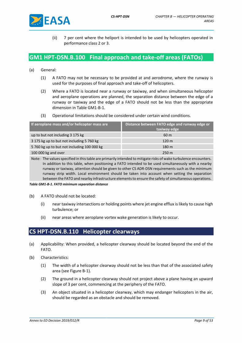
(2) Where a FATO is located near a runway or taxiway, and when simultaneous helicopter and aeroplane operations are planned, the separation distance between the edge of a runway or taxiway and the edge of a FATO should not be less than the appropriate dimension in Table GM1-B-1.
(3) Operational limitations should be considered under certain wind conditions.
If aeroplane mass and/or helicopter mass are Distance between FATO edge and runway edge or taxiway edge
up to but not including 3 175 kg 60 m
3 175 kg up to but not including 5 760 kg 120 m
5 760 kg up to but not including 100 000 kg 180 m
100 000 kg and over 250 m
Note: The values specified in this table are primarily intended to mitigate risks of wake turbulence encounters. In addition to this table, when positioning a FATO intended to be used simultaneously with a nearby runway or taxiway, attention should be given to other CS ADR-DSN requirements such as the minimum runway strip width. Local environment should be taken into account when setting the separation between the FATO and nearby infrastructure elements to ensure the safety of simultaneous operations.
Table GM1-B-1. FATO minimum separation distance
(b) A FATO should not be located:
(i) near taxiway intersections or holding points where jet engine efflux is likely to cause high turbulence; or
(ii) near areas where aeroplane vortex wake generation is likely to occur.
CS HPT-DSN.B.110 Helicopter clearways
(a) Applicability: When provided, a helicopter clearway should be located beyond the end of the FATO.
(b) Characteristics:
(1) The width of a helicopter clearway should not be less than that of the associated safety area (see Figure B-1).
(2) The ground in a helicopter clearway should not project above a plane having an upward slope of 3 per cent, commencing at the periphery of the FATO.
(3) An object situated in a helicopter clearway, which may endanger helicopters in the air, should be regarded as an obstacle and should be removed.
CS-HPT-DSN CHAPTER B — HELICOPTER OPERATING AREAS
Annex to ED Decision 2019/012/R Page 10 of 53
GM1 HPT-DSN.B.110 Helicopter clearways
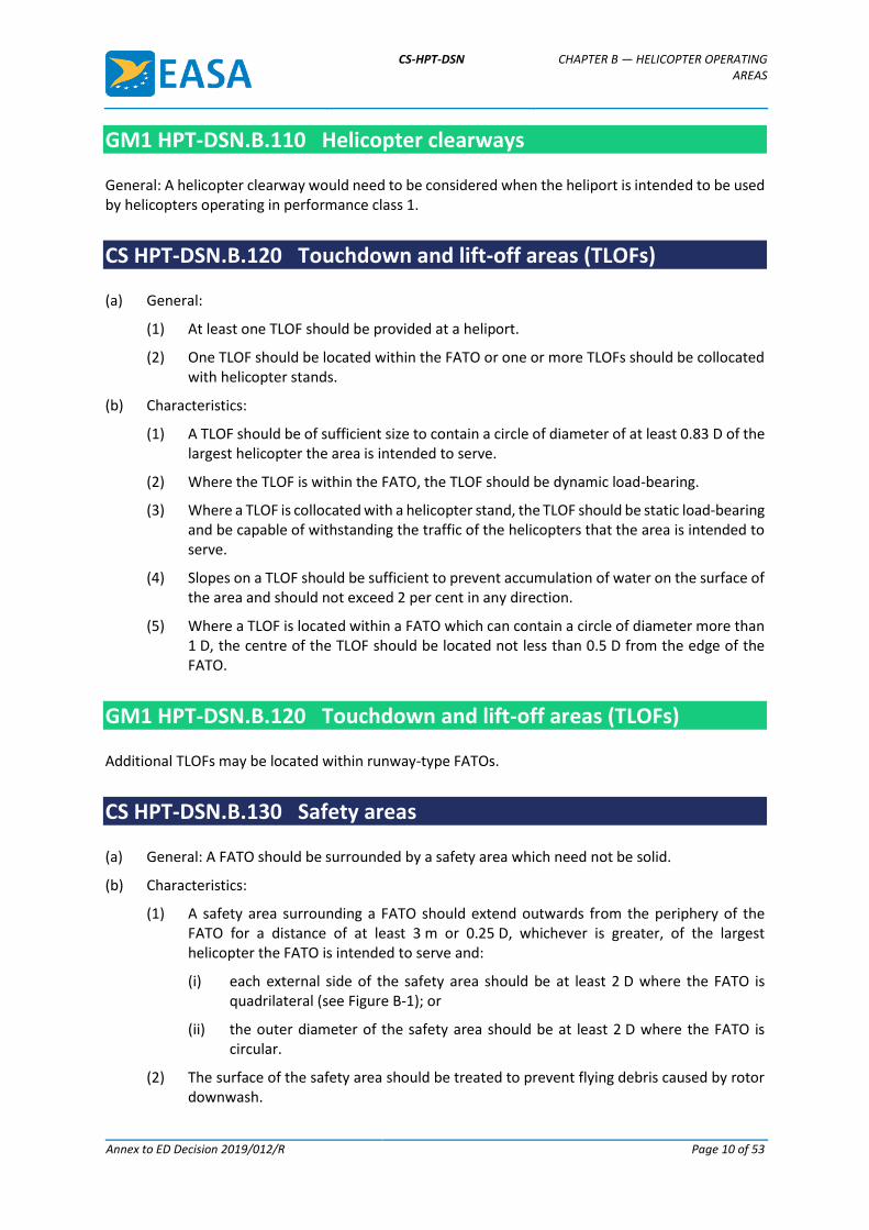
General: A helicopter clearway would need to be considered when the heliport is intended to be used by helicopters operating in performance class 1.
CS HPT-DSN.B.120 Touchdown and lift-off areas (TLOFs)
(a) General:
(1) At least one TLOF should be provided at a heliport.
(2) One TLOF should be located within the FATO or one or more TLOFs should be collocated with helicopter stands.
(b) Characteristics:
(1) A TLOF should be of sufficient size to contain a circle of diameter of at least 0.83 D of the largest helicopter the area is intended to serve.
(2) Where the TLOF is within the FATO, the TLOF should be dynamic load-bearing.
(3) Where a TLOF is collocated with a helicopter stand, the TLOF should be static load-bearing and be capable of withstanding the traffic of the helicopters that the area is intended to serve.
(4) Slopes on a TLOF should be sufficient to prevent accumulation of water on the surface of the area and should not exceed 2 per cent in any direction.
(5) Where a TLOF is located within a FATO which can contain a circle of diameter more than 1 D, the centre of the TLOF should be located not less than 0.5 D from the edge of the FATO.
GM1 HPT-DSN.B.120 Touchdown and lift-off areas (TLOFs)
Additional TLOFs may be located within runway-type FATOs.
CS HPT-DSN.B.130 Safety areas
(a) General: A FATO should be surrounded by a safety area which need not be solid.
(b) Characteristics:
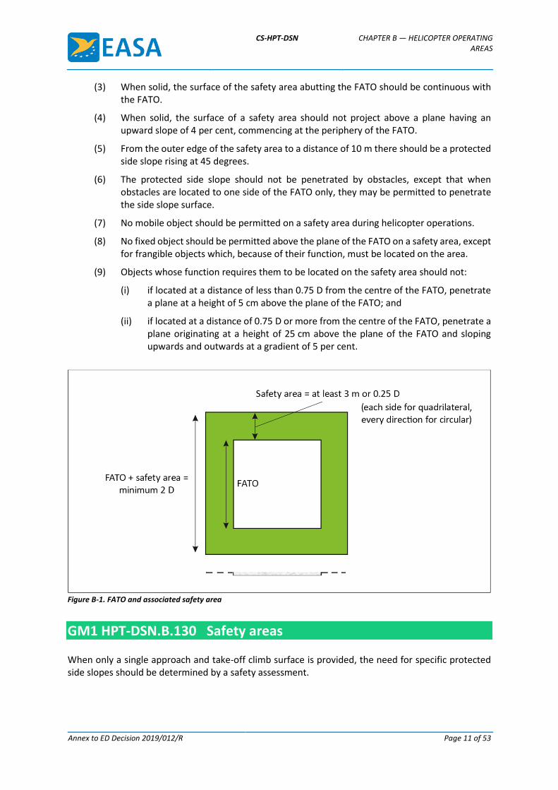
(1) A safety area surrounding a FATO should extend outwards from the periphery of the FATO for a distance of at least 3 m or 0.25 D, whichever is greater, of the largest helicopter the FATO is intended to serve and:
(i) each external side of the safety area should be at least 2 D where the FATO is quadrilateral (see Figure B-1); or
(ii) the outer diameter of the safety area should be at least 2 D where the FATO is circular.
(2) The surface of the safety area should be treated to prevent flying debris caused by rotor downwash.
CS-HPT-DSN CHAPTER B — HELICOPTER OPERATING AREAS
Annex to ED Decision 2019/012/R Page 11 of 53
(3) When solid, the surface of the safety area abutting the FATO should be continuous with the FATO.
(4) When solid, the surface of a safety area should not project above a plane having an upward slope of 4 per cent, commencing at the periphery of the FATO.
(5) From the outer edge of the safety area to a distance of 10 m there should be a protected side slope rising at 45 degrees.
(6) The protected side slope should not be penetrated by obstacles, except that when obstacles are located to one side of the FATO only, they may be permitted to penetrate the side slope surface.
(7) No mobile object should be permitted on a safety area during helicopter operations.
(8) No fixed object should be permitted above the plane of the FATO on a safety area, except for frangible objects which, because of their function, must be located on the area.
(9) Objects whose function requires them to be located on the safety area should not:
(i) if located at a distance of less than 0.75 D from the centre of the FATO, penetrate a plane at a height of 5 cm above the plane of the FATO; and
(ii) if located at a distance of 0.75 D or more from the centre of the FATO, penetrate a plane originating at a height of 25 cm above the plane of the FATO and sloping upwards and outwards at a gradient of 5 per cent.
Figure B-1. FATO and associated safety area
GM1 HPT-DSN.B.130 Safety areas
When only a single approach and take-off climb surface is provided, the need for specific protected side slopes should be determined by a safety assessment.
CS-HPT-DSN CHAPTER C — HELICOPTER TAXIWAYS AND TAXI-ROUTES
Annex to ED Decision 2019/012/R Page 12 of 53
CHAPTER C — HELICOPTER TAXIWAYS AND TAXI-ROUTES
CS HPT-DSN.C.200 Helicopter ground taxiways and helicopter ground taxi-routes
(a) General: A helicopter ground taxiway should be designed to permit the surface movement of a wheeled helicopter under its own power.
(b) Characteristics:
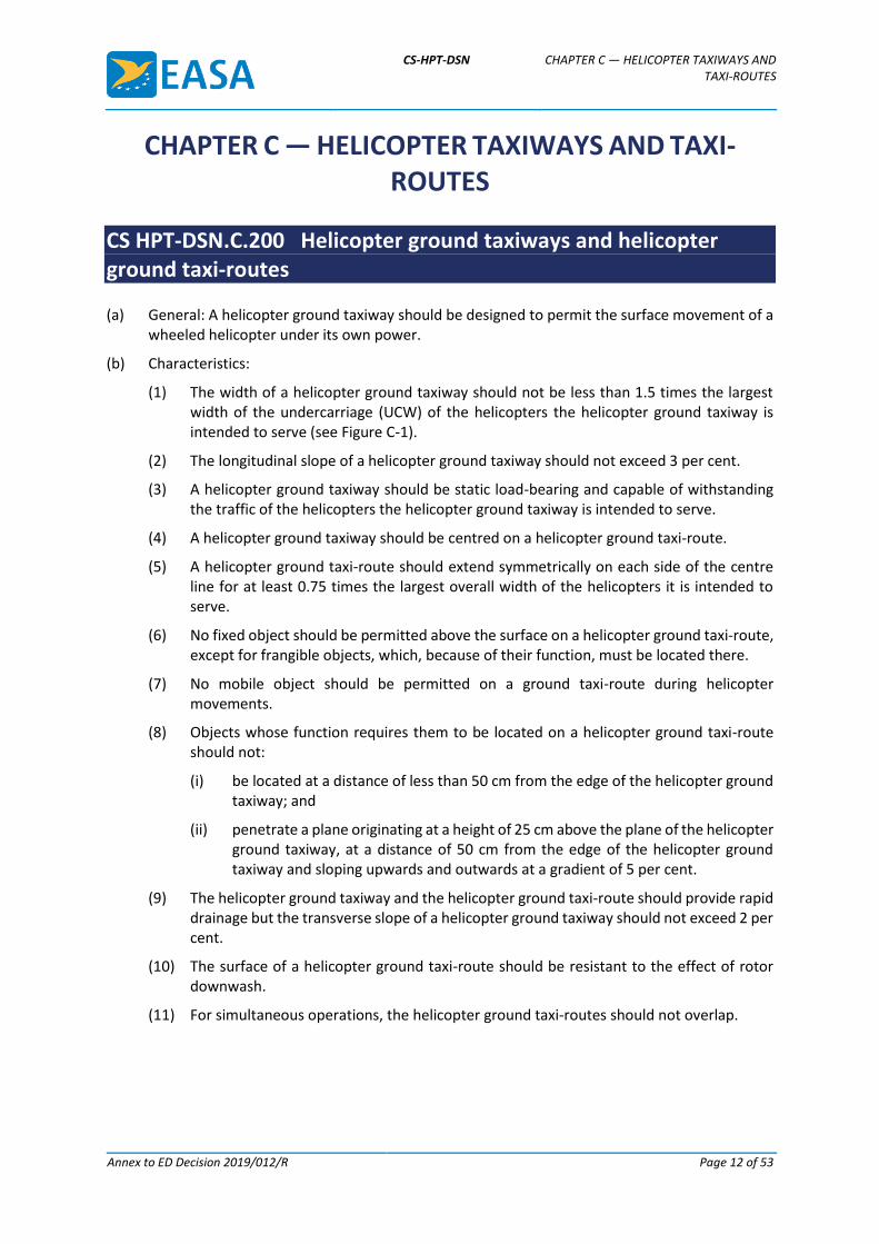
(1) The width of a helicopter ground taxiway should not be less than 1.5 times the largest width of the undercarriage (UCW) of the helicopters the helicopter ground taxiway is intended to serve (see Figure C-1).
(2) The longitudinal slope of a helicopter ground taxiway should not exceed 3 per cent.
(3) A helicopter ground taxiway should be static load-bearing and capable of withstanding the traffic of the helicopters the helicopter ground taxiway is intended to serve.
(4) A helicopter ground taxiway should be centred on a helicopter ground taxi-route.
(5) A helicopter ground taxi-route should extend symmetrically on each side of the centre line for at least 0.75 times the largest overall width of the helicopters it is intended to serve.
(6) No fixed object should be permitted above the surface on a helicopter ground taxi-route, except for frangible objects, which, because of their function, must be located there.
(7) No mobile object should be permitted on a ground taxi-route during helicopter movements.
(8) Objects whose function requires them to be located on a helicopter ground taxi-route should not:
(i) be located at a distance of less than 50 cm from the edge of the helicopter ground taxiway; and
(ii) penetrate a plane originating at a height of 25 cm above the plane of the helicopter ground taxiway, at a distance of 50 cm from the edge of the helicopter ground taxiway and sloping upwards and outwards at a gradient of 5 per cent.
(9) The helicopter ground taxiway and the helicopter ground taxi-route should provide rapid drainage but the transverse slope of a helicopter ground taxiway should not exceed 2 per cent.
(10) The surface of a helicopter ground taxi-route should be resistant to the effect of rotor downwash.
(11) For simultaneous operations, the helicopter ground taxi-routes should not overlap.
CS-HPT-DSN CHAPTER C — HELICOPTER TAXIWAYS AND TAXI-ROUTES
Annex to ED Decision 2019/012/R Page 13 of 53
Figure C-1. Helicopter ground taxi-route/taxiway
GM1 HPT-DSN.C.200 Helicopter ground taxiways and helicopter ground taxi-routes
When a taxiway is intended for use by aeroplanes and helicopters, the provisions for taxiways for aeroplanes and helicopter ground taxiways will be taken into consideration and the more stringent requirements should apply.
CS HPT-DSN.C.210 Helicopter air taxiways and helicopter air taxi-routes
(a) General: A helicopter air taxiway should be designed so as to permit the movement of a helicopter above the surface at a height normally associated with ground effect and at ground speed less than 37 km/h (20 kt).
(b) Characteristics:
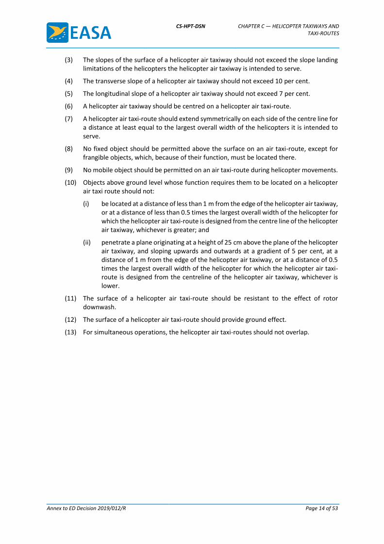
(1) The width of a helicopter air taxiway should be at least two times the largest width of the undercarriage (UCW) of the helicopters that the helicopter air taxiway is intended to serve (see Figure C-2).
(2) The surface of a helicopter air taxiway should be static load-bearing.
CS-HPT-DSN CHAPTER C — HELICOPTER TAXIWAYS AND TAXI-ROUTES
Annex to ED Decision 2019/012/R Page 14 of 53
(3) The slopes of the surface of a helicopter air taxiway should not exceed the slope landing limitations of the helicopters the helicopter air taxiway is intended to serve.
(4) The transverse slope of a helicopter air taxiway should not exceed 10 per cent.
(5) The longitudinal slope of a helicopter air taxiway should not exceed 7 per cent.
(6) A helicopter air taxiway should be centred on a helicopter air taxi-route.
(7) A helicopter air taxi-route should extend symmetrically on each side of the centre line for a distance at least equal to the largest overall width of the helicopters it is intended to serve.
(8) No fixed object should be permitted above the surface on an air taxi-route, except for frangible objects, which, because of their function, must be located there.
(9) No mobile object should be permitted on an air taxi-route during helicopter movements.
(10) Objects above ground level whose function requires them to be located on a helicopter air taxi route should not:
(i) be located at a distance of less than 1 m from the edge of the helicopter air taxiway, or at a distance of less than 0.5 times the largest overall width of the helicopter for which the helicopter air taxi-route is designed from the centre line of the helicopter air taxiway, whichever is greater; and
(ii) penetrate a plane originating at a height of 25 cm above the plane of the helicopter air taxiway, and sloping upwards and outwards at a gradient of 5 per cent, at a distance of 1 m from the edge of the helicopter air taxiway, or at a distance of 0.5 times the largest overall width of the helicopter for which the helicopter air taxi-route is designed from the centreline of the helicopter air taxiway, whichever is lower.
(11) The surface of a helicopter air taxi-route should be resistant to the effect of rotor downwash.
(12) The surface of a helicopter air taxi-route should provide ground effect.
(13) For simultaneous operations, the helicopter air taxi-routes should not overlap.
CS-HPT-DSN CHAPTER C — HELICOPTER TAXIWAYS AND TAXI-ROUTES
Annex to ED Decision 2019/012/R Page 15 of 53
Figure C-2. Helicopter air taxi-route/taxiway
GM1 HPT-DSN.C.210 Helicopter air taxiways and helicopter air taxi-routes
The part of the helicopter air taxi-route that extends symmetrically on each side of the centre line from 0.5 times the largest overall width of the helicopters it is intended to serve to the outermost limit of the helicopter air taxi-route is its protection area.
CS-HPT-DSN CHAPTER D — HELICOPTER STANDS
Annex to ED Decision 2019/012/R Page 16 of 53
CHAPTER D — HELICOPTER STANDS
CS HPT-DSN.D.300 Helicopter stands
(a) Characteristics:
(1) When a TLOF is collocated with a helicopter stand, the protection area of the stand should not overlap the protection area of any other helicopter stand or associated taxi route.
(2) A helicopter stand should provide rapid drainage.
(3) The slope of a helicopter stand in any direction should not exceed 2 per cent.
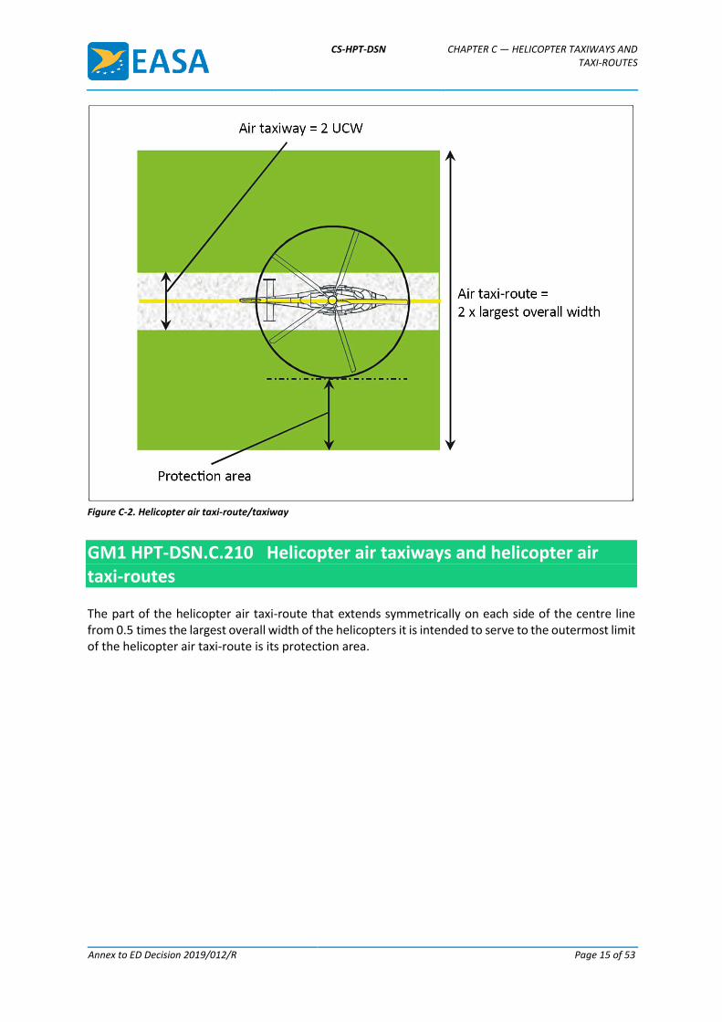
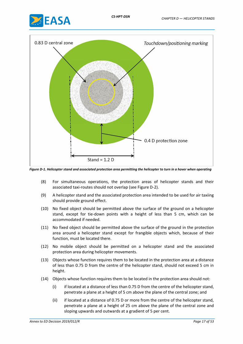
(4) When used by helicopters turning in a hover, a helicopter stand should be of sufficient size to contain a circle of diameter of at least 1.2 D of the largest helicopter the stand is intended to serve (see Figure D-1).
(5) Where a helicopter stand is intended to be used for taxi-through and where the helicopter using the stand is not required to turn, the minimum width of the stand and associated protection area should be that of the taxi-route.
(6) Where a helicopter stand is intended to be used for turning, the minimum overall dimension of the stand and protection area should not be less than 2 D.
(7) Where a helicopter stand is intended to be used for turning, the helicopter stand should be surrounded by a protection area which extends for a distance of 0.4 D from the edge of the helicopter stand.
CS-HPT-DSN CHAPTER D — HELICOPTER STANDS
Annex to ED Decision 2019/012/R Page 17 of 53
Figure D-1. Helicopter stand and associated protection area permitting the helicopter to turn in a hover when operating
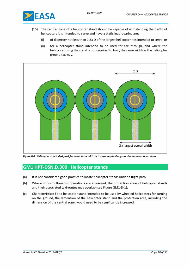
(8) For simultaneous operations, the protection areas of helicopter stands and their associated taxi-routes should not overlap (see Figure D-2).
(9) A helicopter stand and the associated protection area intended to be used for air taxiing should provide ground effect.
(10) No fixed object should be permitted above the surface of the ground on a helicopter stand, except for tie-down points with a height of less than 5 cm, which can be accommodated if needed.
(11) No fixed object should be permitted above the surface of the ground in the protection area around a helicopter stand except for frangible objects which, because of their function, must be located there.
(12) No mobile object should be permitted on a helicopter stand and the associated protection area during helicopter movements.
(13) Objects whose function requires them to be located in the protection area at a distance of less than 0.75 D from the centre of the helicopter stand, should not exceed 5 cm in height.
(14) Objects whose function requires them to be located in the protection area should not:
(i) if located at a distance of less than 0.75 D from the centre of the helicopter stand, penetrate a plane at a height of 5 cm above the plane of the central zone; and
(ii) if located at a distance of 0.75 D or more from the centre of the helicopter stand, penetrate a plane at a height of 25 cm above the plane of the central zone and sloping upwards and outwards at a gradient of 5 per cent.
CS-HPT-DSN CHAPTER D — HELICOPTER STANDS
Annex to ED Decision 2019/012/R Page 18 of 53
(15) The central zone of a helicopter stand should be capable of withstanding the traffic of helicopters it is intended to serve and have a static load-bearing area:
(i) of diameter not less than 0.83 D of the largest helicopter it is intended to serve; or
(ii) for a helicopter stand intended to be used for taxi-through, and where the helicopter using the stand is not required to turn, the same width as the helicopter ground taxiway.
Figure D-2. Helicopter stands designed for hover turns with air taxi-routes/taxiways — simultaneous operations
GM1 HPT-DSN.D.300 Helicopter stands
(a) It is not considered good practice to locate helicopter stands under a flight path.
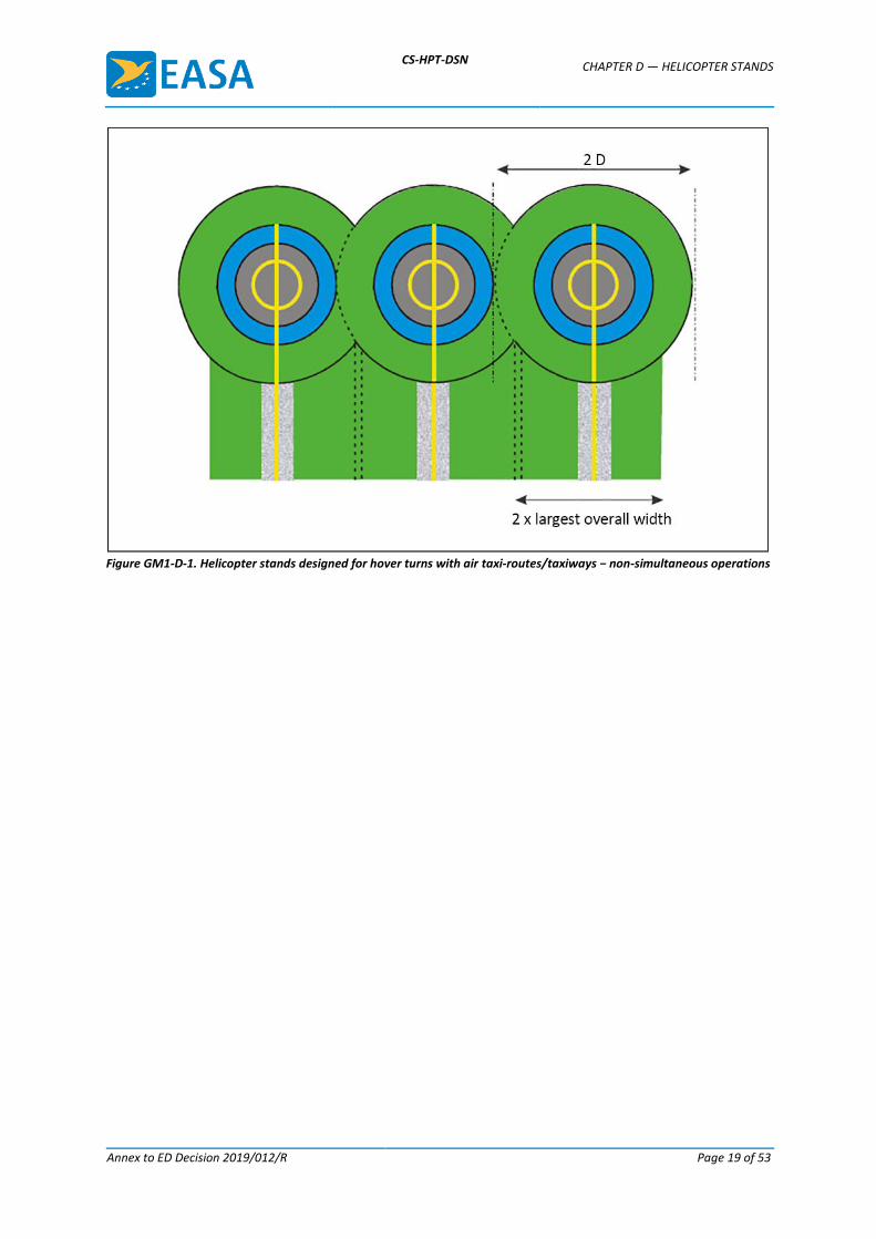
(b) Where non-simultaneous operations are envisaged, the protection areas of helicopter stands and their associated taxi-routes may overlap (see Figure GM1-D-1).
(c) Characteristics: For a helicopter stand intended to be used by wheeled helicopters for turning on the ground, the dimension of the helicopter stand and the protection area, including the dimension of the central zone, would need to be significantly increased.
CS-HPT-DSN CHAPTER D — HELICOPTER STANDS
Annex to ED Decision 2019/012/R Page 19 of 53
Figure GM1-D-1. Helicopter stands designed for hover turns with air taxi-routes/taxiways − non-simultaneous operations
CS-HPT-DSN CHAPTER E — OBSTACLE LIMITATION SURFACES AND REQUIREMENTS
Annex to ED Decision 2019/012/R Page 20 of 53
CHAPTER E — OBSTACLE LIMITATION SURFACES AND
REQUIREMENTS
CS HPT-DSN.E.400 Applicability
The purpose of the obstacle limitation surfaces is to define the airspace around heliports so as to permit intended helicopter operations to be conducted safely.
GM1 HPT-DSN.E.400 Applicability
Intentionally left blank
CS HPT-DSN.E.410 Approach surface
(a) Applicability: The purpose of an approach surface is to protect a helicopter during the final approach to the FATO by defining an area that should be kept free from obstacles to protect a helicopter in the final phase of the approach to land manoeuvre.
(b) Description: An inclined plane or a combination of planes or, when a turn is involved, a complex surface sloping upwards from the end of the safety area and centred on a line passing through the centre of the FATO (see Figures E-1, E-2, E-3 and E-4 and Table E-1).
(c) Characteristics:
(1) The limits of an approach surface should comprise:
(i) an inner edge horizontal and equal in length to the minimum specified width/diameter of the FATO plus the safety area, perpendicular to the centre line of the approach surface and located at the outer edge of the safety area;
(ii) two side edges originating at the ends of the inner edge diverging uniformly at a specified rate from the vertical plane containing the centre line of the FATO; and
(iii) an outer edge horizontal and perpendicular to the centre line of the approach surface and at a specified height of 152 m (500 ft) above the elevation of the FATO.
(2) The elevation of the inner edge should be the elevation of the FATO at the point on the inner edge that is intersected by the centre line of the approach surface. For heliports intended to be used by helicopters operated in performance class 1, the inclined plane may be raised directly above the FATO.
(3) The slope(s) of the approach surface should be measured in the vertical plane containing the centre line of the surface.
(4) In the case of an approach surface involving a turn, the surface should be a complex surface containing the horizontal normals to its centre line and the slope of the centre line should be the same as that for a straight approach surface (see Figure E-3).
(5) In the case of an approach surface involving a turn, the surface should not contain more than one curved portion.
CS-HPT-DSN CHAPTER E — OBSTACLE LIMITATION SURFACES AND REQUIREMENTS
Annex to ED Decision 2019/012/R Page 21 of 53
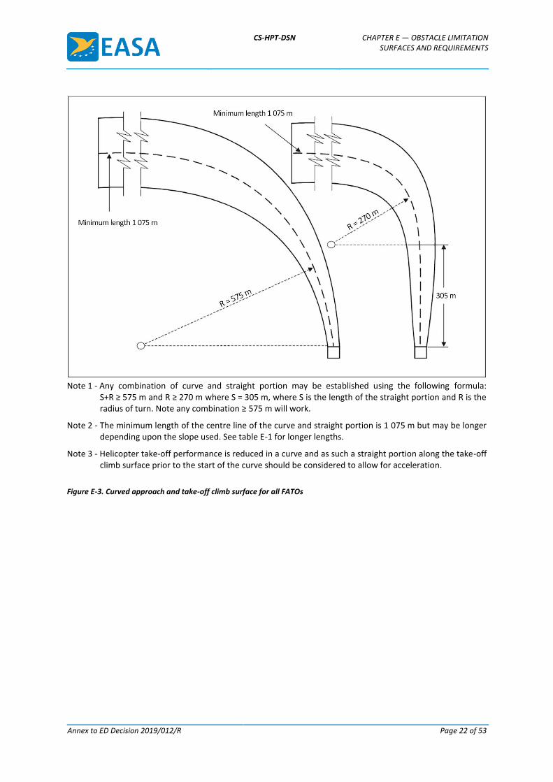
(6) Where a curved portion of an approach surface is provided, the sum of the radius of the arc defining the centre line of the approach surface and the length of the straight portion originating at the inner edge should not be less than 575 m.
(7) Any variation in the direction of the centre line of an approach surface should be designed so as not to necessitate a turn radius less than 270 m.
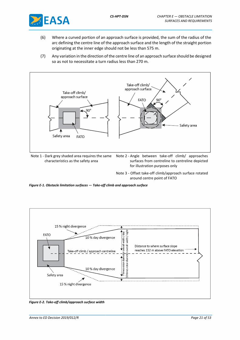
Note 1 - Dark grey shaded area requires the same
characteristics as the safety area Note 2 - Angle between take-off climb/ approaches
surfaces from centreline to centreline depicted for illustration purposes only
Note 3 - Offset take-off climb/approach surface rotated around centre point of FATO
Figure E-1. Obstacle limitation surfaces — Take-off climb and approach surface
Figure E-2. Take-off climb/approach surface width
CS-HPT-DSN CHAPTER E — OBSTACLE LIMITATION SURFACES AND REQUIREMENTS
Annex to ED Decision 2019/012/R Page 22 of 53
Note 1 - Any combination of curve and straight portion may be established using the following formula:
S+R ≥ 575 m and R ≥ 270 m where S = 305 m, where S is the length of the straight portion and R is the radius of turn. Note any combination ≥ 575 m will work.
Note 2 - The minimum length of the centre line of the curve and straight portion is 1 075 m but may be longer depending upon the slope used. See table E-1 for longer lengths.
Note 3 - Helicopter take-off performance is reduced in a curve and as such a straight portion along the take-off climb surface prior to the start of the curve should be considered to allow for acceleration.
Figure E-3. Curved approach and take-off climb surface for all FATOs
CS-HPT-DSN CHAPTER E — OBSTACLE LIMITATION SURFACES AND REQUIREMENTS
Annex to ED Decision 2019/012/R Page 23 of 53
SURFACE AND DIMENSIONS
SLOPE DESIGN CATEGORIES
A B C
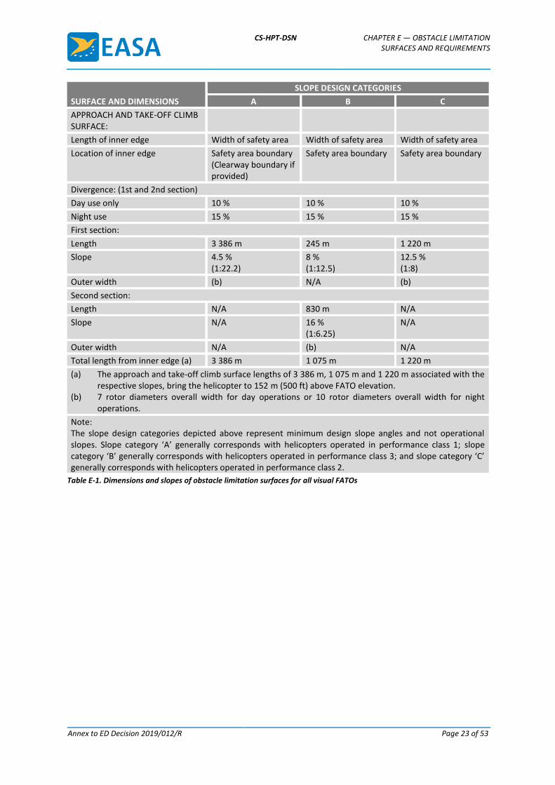
APPROACH AND TAKE-OFF CLIMB SURFACE:
Length of inner edge Width of safety area Width of safety area Width of safety area
Location of inner edge Safety area boundary (Clearway boundary if provided)
Safety area boundary Safety area boundary
Divergence: (1st and 2nd section)
Day use only 10 % 10 % 10 %
Night use 15 % 15 % 15 %
First section:
Length 3 386 m 245 m 1 220 m
Slope 4.5 % (1:22.2)
8 % (1:12.5)
12.5 % (1:8)
Outer width (b) N/A (b)
Second section:
Length N/A 830 m N/A
Slope N/A 16 % (1:6.25)
N/A
Outer width N/A (b) N/A
Total length from inner edge (a) 3 386 m 1 075 m 1 220 m
(a) The approach and take-off climb surface lengths of 3 386 m, 1 075 m and 1 220 m associated with the respective slopes, bring the helicopter to 152 m (500 ft) above FATO elevation.
(b) 7 rotor diameters overall width for day operations or 10 rotor diameters overall width for night operations.
Note: The slope design categories depicted above represent minimum design slope angles and not operational slopes. Slope category ‘A’ generally corresponds with helicopters operated in performance class 1; slope category ‘B’ generally corresponds with helicopters operated in performance class 3; and slope category ‘C’ generally corresponds with helicopters operated in performance class 2.
Table E-1. Dimensions and slopes of obstacle limitation surfaces for all visual FATOs
CS-HPT-DSN CHAPTER E — OBSTACLE LIMITATION SURFACES AND REQUIREMENTS
Annex to ED Decision 2019/012/R Page 24 of 53
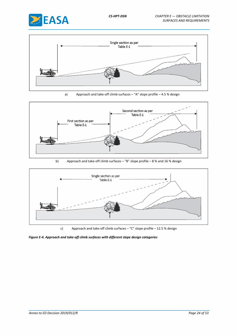
a) Approach and take-off climb surfaces – “A” slope profile – 4.5 % design
b) Approach and take-off climb surfaces – “B” slope profile – 8 % and 16 % design
c) Approach and take-off climb surfaces – “C” slope profile – 12.5 % design
Figure E-4. Approach and take-off climb surfaces with different slope design categories
CS-HPT-DSN CHAPTER E — OBSTACLE LIMITATION SURFACES AND REQUIREMENTS
Annex to ED Decision 2019/012/R Page 25 of 53
GM1 HPT-DSN.E.410 Approach surface
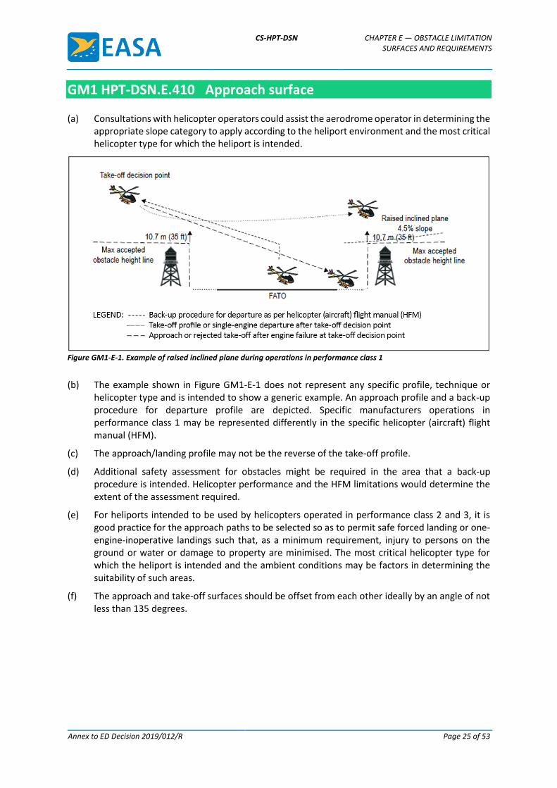
(a) Consultations with helicopter operators could assist the aerodrome operator in determining the appropriate slope category to apply according to the heliport environment and the most critical helicopter type for which the heliport is intended.
Figure GM1-E-1. Example of raised inclined plane during operations in performance class 1
(b) The example shown in Figure GM1-E-1 does not represent any specific profile, technique or helicopter type and is intended to show a generic example. An approach profile and a back-up procedure for departure profile are depicted. Specific manufacturers operations in performance class 1 may be represented differently in the specific helicopter (aircraft) flight manual (HFM).
(c) The approach/landing profile may not be the reverse of the take-off profile.
(d) Additional safety assessment for obstacles might be required in the area that a back-up procedure is intended. Helicopter performance and the HFM limitations would determine the extent of the assessment required.
(e) For heliports intended to be used by helicopters operated in performance class 2 and 3, it is good practice for the approach paths to be selected so as to permit safe forced landing or one-engine-inoperative landings such that, as a minimum requirement, injury to persons on the ground or water or damage to property are minimised. The most critical helicopter type for which the heliport is intended and the ambient conditions may be factors in determining the suitability of such areas.
(f) The approach and take-off surfaces should be offset from each other ideally by an angle of not less than 135 degrees.
CS-HPT-DSN CHAPTER E — OBSTACLE LIMITATION SURFACES AND REQUIREMENTS
Annex to ED Decision 2019/012/R Page 26 of 53
CS HPT-DSN.E.420 Take-off climb surface
(a) Applicability: The purpose of the take-off climb surface is to protect a helicopter on take-off and during climb-out.
(b) Description: An inclined plane, a combination of planes or, when a turn is involved, a complex surface sloping upwards from the end of the safety area and centred on a line passing through the centre of the FATO (see Figures E-1, E-2, E-3, and E-4, and Table E-1).
(c) Characteristics:
(1) The limits of a take-off climb surface should comprise:
(i) an inner edge horizontal and equal in length to the minimum specified width/diameter of the FATO plus the safety area, perpendicular to the centre line of the take-off climb surface and located at the outer edge of the safety area;
(ii) two side edges originating at the ends of the inner edge and diverging uniformly at a specified rate from the vertical plane containing the centre line of the FATO; and
(iii) an outer edge horizontal and perpendicular to the centre line of the take-off climb surface and at a specified height of 152 m (500 ft) above the elevation of the FATO.
(2) The elevation of the inner edge should be the elevation of the FATO at the point on the inner edge that is intersected by the centre line of the take-off climb surface. For heliports intended to be used by helicopters operated in performance class 1, the inclined plane may be raised directly above the FATO.
(3) Where a clearway is provided the elevation of the inner edge of the take-off climb surface should be located at the outer edge of the clearway at the highest point on the ground based on the centre line of the clearway.
(4) In the case of a straight take-off climb surface, the slope should be measured in the vertical plane containing the centre line of the surface.
(5) In the case of a take-off climb surface involving a turn, the surface should be a complex surface containing the horizontal normals to its centre line and the slope of the centre line should be the same as that for a straight take-off climb surface (see Figure E-3).
(6) In the case of a take-off climb surface involving a turn, the surface should not contain more than one curved portion.
(7) Where a curved portion of a take-off climb surface is provided, the sum of the radius of the arc defining the centre line of the take-off climb surface and the length of the straight portion originating at the inner edge should not be less than 575 m.
(8) Any variation in the direction of the centre line of a take-off climb surface should be designed so as not to necessitate a turn of radius less than 270 m.
GM1 HPT-DSN.E.420 Take-off climb surface
(a) Helicopter take-off performance is reduced in a curve, so a straight portion along the take-off climb surface prior to the start of the curve allows for acceleration.
(b) For heliports intended to be used by helicopters operated in performance class 2 and 3, it is an operational requirement for departure paths to be selected so as to permit safe forced landings or one-engine-inoperative landings such that injury to persons on the ground or damage to
CS-HPT-DSN CHAPTER E — OBSTACLE LIMITATION SURFACES AND REQUIREMENTS
Annex to ED Decision 2019/012/R Page 27 of 53
property are minimised. The most critical helicopter type for which the heliport is intended and the ambient conditions may be factors in determining the suitability of such areas.
(c) The approach and take-off surfaces should be offset from each other ideally by an angle of not less than 135 degrees.
CS HPT-DSN.E.430 Obstacle limitation requirements
(a) General: The following obstacle limitation surfaces should be established for a FATO:
(1) take-off climb surface; and
(2) approach surface.
(b) Characteristics:
(1) The slopes of the obstacle limitation surfaces should not be greater than, and their other dimensions not less than, those specified in Table E-1 and should be located as shown in Figures E-1, E-2 and E-4.
(2) Where a heliport visual approach slope indicator is installed, additional obstacle protection surfaces should be provided, as specified in CS HPT-DSN.F.660, which can be more demanding than the obstacle limitation surfaces prescribed in Table E-1.
(3) For heliports that have an approach/take-off climb surface with a 4.5 per cent slope design, objects can be permitted to penetrate the obstacle limitation surface, if after a safety assessment, it is determined that the object would not adversely affect the safety or significantly affect the regularity of operations of helicopters.
(4) New objects or extensions of existing objects should not be permitted above the approach or take-off climb surfaces except when shielded by an existing immovable object or when after a safety assessment, it is determined that the object would not adversely affect the safety or significantly affect the regularity of operations of helicopters.
(5) Existing objects above the approach and take off climb surfaces should, as far as practicable, be removed except when the object is shielded by an existing immovable object or when after a safety assessment, it is determined that the object would not adversely affect the safety or significantly affect the regularity of operations of helicopters.
(6) When only a single approach and take-off climb surface is provided, a safety assessment should be undertaken considering as a minimum, the following factors:
(i) the area/terrain over which the flight is being conducted;
(ii) the obstacle environment surrounding the heliport;
(iii) the performance and operating limitations of helicopters intending to use the heliport; and
(iv) the local meteorological conditions including the prevailing winds.
GM1 HPT-DSN.E.430 Obstacle limitation requirements
Intentionally left blank
CS-HPT-DSN CHAPTER F — VISUAL AIDS
Annex to ED Decision 2019/012/R Page 28 of 53
CHAPTER F — VISUAL AIDS
CS HPT-DSN.F.500 General
(a) When a FATO has similar characteristics to a runway, the applicable CSs are provided in the paragraphs below entitled ‘runway-type FATO’.
(b) For all other types of FATO, the applicable CSs are provided in the paragraphs below entitled ‘All FATOs except runway-type FATOs’.
GM1 HPT-DSN.F.500 General
When a runway is marked in accordance with the provisions of CS-ADR-DSN, and is utilised as a FATO, no additional runway markings or lighting are required for helicopter use.
CS HPT-DSN.F.510 Wind direction indicators
Applicability: A heliport should be equipped with at least one wind direction indicator.
GM1 HPT-DSN.F.510 Wind direction indicators
(a) General: If the wind direction indicators serving the aerodrome do not clearly indicate the correct wind information at the heliport, additional wind direction indicators should be installed in order to provide wind information to the pilot during approach and take-off.
(b) Location:
(1) A wind direction indicator should be located so as to indicate the wind conditions over the FATO and TLOF and in such a way as to be free from the effects of airflow disturbances caused by nearby objects or rotor downwash. It should be visible from a helicopter in flight, in a hover or on the movement area.
(2) Where a TLOF and/or FATO are subject to a disturbed airflow, additional wind direction indicators located close to the area should be provided to indicate the surface wind on the area.
(c) Characteristics:
(1) A wind direction indicator should give a clear indication of the direction of the wind and a general indication of the wind speed.
(2) A wind direction indicator for the heliport should be a truncated cone made of lightweight fabric and should have the following minimum dimensions:
(i) Length 2.4 m,
(ii) Diameter (larger end) 0.6 m, and
(iii) Diameter (smaller end) 0.3 m.
CS-HPT-DSN CHAPTER F — VISUAL AIDS
Annex to ED Decision 2019/012/R Page 29 of 53
(3) The colour of the wind direction indicator should be so selected as to make it clearly visible and understandable from a height of at least 200 m (650 ft) above the heliport, having regard to the background:
(i) where practicable, a single colour, preferably white or orange, should be used;
(ii) where a combination of two colours is required to give adequate conspicuity against changing backgrounds, they should preferably be orange and white, red and white, or black and white, and should be arranged in five alternate bands, the first and last band being the darker colour.
(d) A wind direction indicator at a heliport intended for use at night should be illuminated.
CS HPT-DSN.F.520 Heliport identification marking
(a) Applicability: Heliport identification markings should be provided at a heliport.
(b) Location:
(1) For runway-type FATOs:
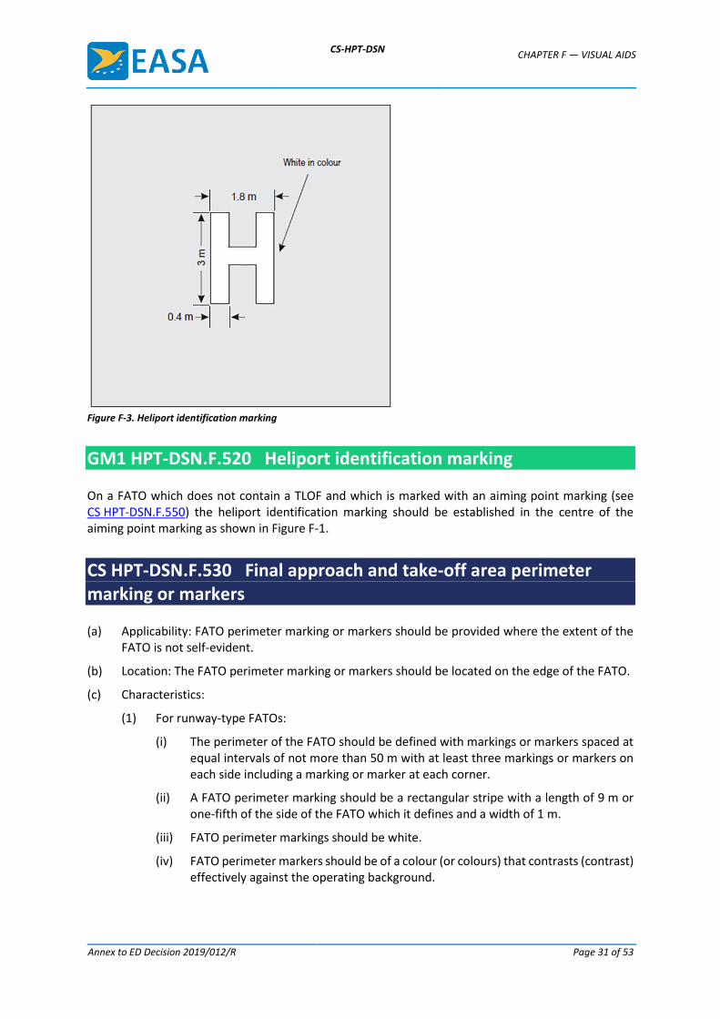
A heliport identification marking should be located in the FATO and when used in conjunction with FATO designation markings, should be displayed at each end of the FATO (see Figure F-2).
(2) For all FATOs except runway-type FATOs:
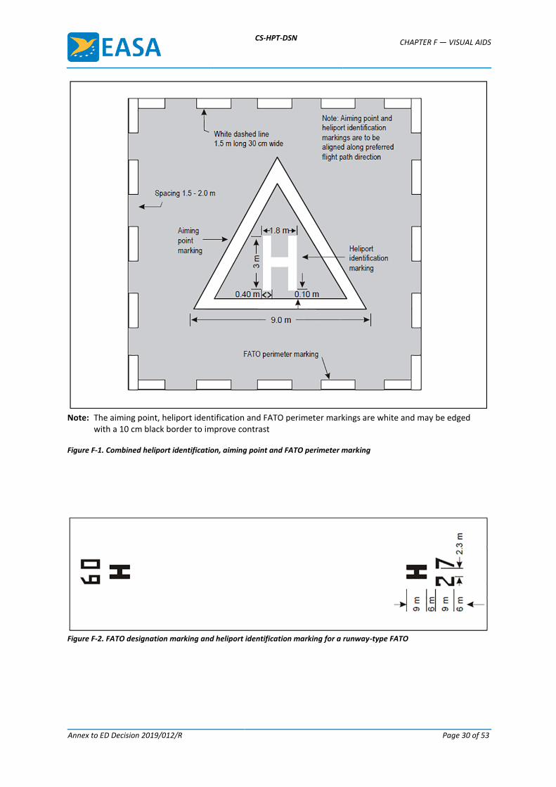
(i) A heliport identification marking should be located at or near the centre of the FATO (see Figure F-1).
(ii) On a FATO which contains a TLOF, a heliport identification marking should be located in the FATO so that the position of it coincides with the centre of the TLOF.
(c) Characteristics:
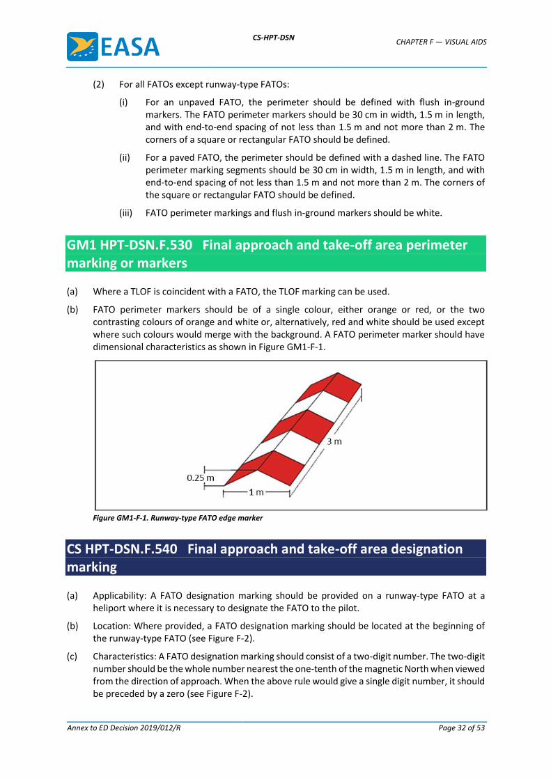
(1) A heliport identification marking should consist of a letter ‘H’, white in colour. The dimensions of the ‘H’ marking should be no less than those shown in Figure F-3.
(2) Where the ‘H’ marking is used for a runway-type FATO, its dimensions should be increased by a factor of 3 (see Figures F-2 and F-3).
(3) A heliport identification marking should be oriented with the cross arm of the ‘H’ at right angles to the preferred final approach direction.
CS-HPT-DSN CHAPTER F — VISUAL AIDS
Annex to ED Decision 2019/012/R Page 30 of 53
Note: The aiming point, heliport identification and FATO perimeter markings are white and may be edged
with a 10 cm black border to improve contrast Figure F-1. Combined heliport identification, aiming point and FATO perimeter marking
Figure F-2. FATO designation marking and heliport identification marking for a runway-type FATO
CS-HPT-DSN CHAPTER F — VISUAL AIDS
Annex to ED Decision 2019/012/R Page 31 of 53
Figure F-3. Heliport identification marking
GM1 HPT-DSN.F.520 Heliport identification marking
On a FATO which does not contain a TLOF and which is marked with an aiming point marking (see CS HPT-DSN.F.550) the heliport identification marking should be established in the centre of the aiming point marking as shown in Figure F-1.
CS HPT-DSN.F.530 Final approach and take-off area perimeter marking or markers
(a) Applicability: FATO perimeter marking or markers should be provided where the extent of the FATO is not self-evident.
(b) Location: The FATO perimeter marking or markers should be located on the edge of the FATO.
(c) Characteristics:
(1) For runway-type FATOs:
(i) The perimeter of the FATO should be defined with markings or markers spaced at equal intervals of not more than 50 m with at least three markings or markers on each side including a marking or marker at each corner.
(ii) A FATO perimeter marking should be a rectangular stripe with a length of 9 m or one-fifth of the side of the FATO which it defines and a width of 1 m.
(iii) FATO perimeter markings should be white.
(iv) FATO perimeter markers should be of a colour (or colours) that contrasts (contrast) effectively against the operating background.
CS-HPT-DSN CHAPTER F — VISUAL AIDS
Annex to ED Decision 2019/012/R Page 32 of 53
(2) For all FATOs except runway-type FATOs:
(i) For an unpaved FATO, the perimeter should be defined with flush in-ground markers. The FATO perimeter markers should be 30 cm in width, 1.5 m in length, and with end-to-end spacing of not less than 1.5 m and not more than 2 m. The corners of a square or rectangular FATO should be defined.
(ii) For a paved FATO, the perimeter should be defined with a dashed line. The FATO perimeter marking segments should be 30 cm in width, 1.5 m in length, and with end-to-end spacing of not less than 1.5 m and not more than 2 m. The corners of the square or rectangular FATO should be defined.
(iii) FATO perimeter markings and flush in-ground markers should be white.
GM1 HPT-DSN.F.530 Final approach and take-off area perimeter marking or markers
(a) Where a TLOF is coincident with a FATO, the TLOF marking can be used.
(b) FATO perimeter markers should be of a single colour, either orange or red, or the two contrasting colours of orange and white or, alternatively, red and white should be used except where such colours would merge with the background. A FATO perimeter marker should have dimensional characteristics as shown in Figure GM1-F-1.
Figure GM1-F-1. Runway-type FATO edge marker
CS HPT-DSN.F.540 Final approach and take-off area designation marking
(a) Applicability: A FATO designation marking should be provided on a runway-type FATO at a heliport where it is necessary to designate the FATO to the pilot.
(b) Location: Where provided, a FATO designation marking should be located at the beginning of the runway-type FATO (see Figure F-2).
(c) Characteristics: A FATO designation marking should consist of a two-digit number. The two-digit number should be the whole number nearest the one-tenth of the magnetic North when viewed from the direction of approach. When the above rule would give a single digit number, it should be preceded by a zero (see Figure F-2).
CS-HPT-DSN CHAPTER F — VISUAL AIDS
Annex to ED Decision 2019/012/R Page 33 of 53
GM1 HPT-DSN.F.540 Final approach and take-off area designation marking
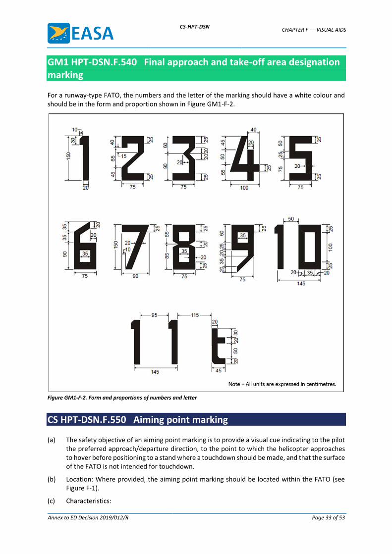
For a runway-type FATO, the numbers and the letter of the marking should have a white colour and should be in the form and proportion shown in Figure GM1-F-2.
Figure GM1-F-2. Form and proportions of numbers and letter
CS HPT-DSN.F.550 Aiming point marking
(a) The safety objective of an aiming point marking is to provide a visual cue indicating to the pilot the preferred approach/departure direction, to the point to which the helicopter approaches to hover before positioning to a stand where a touchdown should be made, and that the surface of the FATO is not intended for touchdown.
(b) Location: Where provided, the aiming point marking should be located within the FATO (see Figure F-1).
(c) Characteristics:
CS-HPT-DSN CHAPTER F — VISUAL AIDS
Annex to ED Decision 2019/012/R Page 34 of 53
(i) The aiming point marking should be an equilateral triangle with a minimum side length of 9.0 metres, with the bisector of one of the angles aligned with the preferred approach direction.
(ii) The marking should consist of continuous white lines, 1.0 m in width (see Figures F-1 and F-12).
GM1 HPT-DSN.F.550 Aiming point marking
For all FATOs except runway-type FATOs, the aiming point marking should be located at the centre of the FATO, as shown in Figure F-1.
CS HPT-DSN.F.560 Touchdown and lift-off area perimeter marking
(a) The safety objective of the touchdown and lift-off area perimeter marking is to provide to the pilot a clear indication of a TLOF.
(b) Applicability: When the perimeter of the TLOF is not self-evident, a TLOF perimeter marking should be displayed on a TLOF located in a FATO.
(c) Location: Where provided, the TLOF perimeter marking should be located along the edge of the TLOF.
(d) Characteristics: A TLOF perimeter marking should consist of a continuous white line with a width of at least 30 cm.
GM1 HPT-DSN.F.560 Touchdown and lift-off area perimeter marking
A TLOF perimeter marking should be provided on each TLOF collocated with a helicopter stand.
CS HPT-DSN.F.570 Touchdown/positioning marking
(a) Applicability:
(1) A touchdown/positioning marking should be provided where it is necessary for a helicopter to touch down and/or be accurately positioned.
(2) A touchdown/positioning marking should be provided on a helicopter stand designed for turning.
(b) Location:
(1) A touchdown/positioning marking should be located so that when the pilot’s seat is over the marking, the whole of the undercarriage should be within the TLOF and all parts of the helicopter should be clear of any obstacle by a safe margin.
(2) On a heliport, the centre of the touchdown/positioning marking should be located at the centre of the TLOF, except the centre of the touchdown/positioning marking may be offset away from the centre of the TLOF where a safety assessment indicates such
CS-HPT-DSN CHAPTER F — VISUAL AIDS
Annex to ED Decision 2019/012/R Page 35 of 53
offsetting to be necessary, and providing that a marking that is so offset would not adversely affect safety.
(3) For a helicopter stand designed for hover turning, the touchdown/positioning marking should be located in the centre of the central zone (see Figure D-1).
(c) Characteristics:
(1) A touchdown/positioning marking should be a yellow circle and have a line width of at least 0.5 m.
(2) The inner diameter of the touchdown/positioning marking should be 0.5 D of the largest helicopter the TLOF and/or the helicopter stand is intended to serve.
GM1 HPT-DSN.F.570 Touchdown/positioning marking
Intentionally left blank
CS HPT-DSN.F.580 Heliport name marking
(a) Applicability: A heliport name marking should be provided at a heliport where there is insufficient alternative means of visual identification.
(b) Characteristics: A heliport name marking should consist of the name or the alphanumeric designator of the heliport as used in radio (R/T) communications.
GM1 HPT-DSN.F.580 Heliport name marking
(a) Location: The heliport name marking should be displayed on the heliport so as to be visible, as far as practicable, at all angles above the horizontal.
(b) Characteristics:
(1) A heliport name marking intended for use at night or during conditions of poor visibility should be illuminated, either internally or externally.
(2) The colour of the marking should contrast with the background and preferably be white.
(3) Runway-type FATOs: The characters of the marking should be not less than 3 m in height.
(4) All FATOs except runway-type FATOs: The characters of the marking should be not less than 1.5 m in height.
CS HPT-DSN.F.590 Helicopter ground taxiway markings and markers
(a) Applicability:
(1) The specifications for runway-holding position markings defined in CS ADR-DSN.L.575 and for intermediate holding position marking defined in CS ADR-DSN.L.580 are equally applicable to taxiways intended for ground taxiing of helicopters.
(2) The centre line of a helicopter ground taxiway should be identified with a marking.
CS-HPT-DSN CHAPTER F — VISUAL AIDS
Annex to ED Decision 2019/012/R Page 36 of 53
(3) The edges of a helicopter ground taxiway, if not self-evident, should be identified with markers or markings.
(b) Location:
(1) Helicopter ground taxiway markings should be along the centre line, and, if provided, along the edges of a helicopter ground taxiway.
(2) Helicopter ground taxiway edge markers should be located at a distance of 0.5 m to 3 m beyond the edge of the helicopter ground taxiway.
(3) Where provided, helicopter ground taxiway edge markers should be spaced at intervals of not more than 15 m on each side of straight sections and 7.5 m on each side of curved sections with a minimum of four equally spaced markers per section.
(c) Characteristics:
(1) A helicopter ground taxiway centre line marking should be a continuous yellow line 15 cm in width.
(2) Helicopter ground taxiway edge markings should be a continuous double yellow line, each 15 cm in width, and spaced 15 cm apart (nearest edge to nearest edge).
(3) A helicopter ground taxiway edge marker should not exceed the height of a plane originating at a height of 25 cm above the plane of the helicopter ground taxiway, at a distance of 0.5 m from the edge of the helicopter ground taxiway and sloping upwards and outwards at a gradient of 5 per cent to a distance of 3 m beyond the edge of the helicopter ground taxiway.
(4) Helicopter ground taxiway edge markers should be frangible to the wheeled undercarriage of helicopters.
(5) A helicopter ground taxiway edge marker should be blue.
(6) If the helicopter ground taxiway is to be used at night, the edge markers should be internally illuminated or retro-reflective.
GM1 HPT-DSN.F.590 Helicopter ground taxiway markings and markers
(a) Ground taxi-routes are not required to be marked.
(b) Where necessary, signage should be provided on an aerodrome to indicate that a ground taxiway is suitable only for the use of helicopters.
(c) A helicopter ground taxiway edge marker should not present a hazard for aircraft operations.
CS HPT-DSN.F.600 Helicopter air taxiway markings and markers
(a) Applicability:
(1) The specifications for runway-holding position markings defined in CS ADR-DSN.L.575 and intermediate holding position marking defined in CS ADR-DSN.L.580 are equally applicable to taxiways intended for air taxiing of helicopters.
(2) The centre line of a helicopter air taxiway or, if not self-evident, the edges of a helicopter air taxiway, should be identified with markers or markings.
CS-HPT-DSN CHAPTER F — VISUAL AIDS
Annex to ED Decision 2019/012/R Page 37 of 53
(b) Location:
(1) A helicopter air taxiway centre line marking or flush in-ground centre line marker should be located along the centre line of the helicopter air taxiway.
(2) Helicopter air taxiway edge markings should be located along the edges of a helicopter air taxiway.
(3) Helicopter air taxiway edge markers should be located at a distance of 1 m to 3 m beyond the edge of the helicopter air taxiway.
(c) Characteristics:
(1) A helicopter air taxiway centre line should be marked with a continuous yellow line 15 cm in width, when on a paved surface.
(2) The edges of a helicopter air taxiway, when on a paved surface, should be marked with continuous double yellow lines each 15 cm in width, and spaced 15 cm apart (nearest edge to nearest edge).
(3) Where a helicopter air taxiway is located on an unpaved surface and painted markings of a helicopter air taxiway centre line cannot be provided, it should be marked with flush in-ground 15 cm wide and approximately 1.5 m in length yellow markers, spaced at intervals of not more than 30 m on straight sections and not more than 15 m on curves, with a minimum of four equally spaced markers per section.
(4) Helicopter air taxiway edge markers, where provided, should be spaced at intervals of not more than 30 m on each side of straight sections and not more than 15 m on each side of curves, with a minimum of four equally spaced markers per section.
(5) Helicopter air taxiway edge markers should be frangible.
(6) Helicopter air taxiway edge markers should not penetrate a plane originating at a height of 25 cm above the plane of the helicopter air taxiway, at a distance of 1 m from the edge of the helicopter air taxiway and sloping upwards and outwards at a gradient of 5 per cent to a distance of 3 m beyond the edge of the helicopter air taxiway.
(7) A helicopter air taxiway edge marker should be of a colour (or colours) that contrasts (contrast) effectively against the operating background. The red colour should not be used for markers.
(8) If the helicopter air taxiway is to be used at night, helicopter air taxiway edge markers should be either internally illuminated or retro-reflective.
GM1 HPT-DSN.F.600 Helicopter air taxiway markings and markers
(a) Helicopter air taxi-routes are not required to be marked.
(b) Where a helicopter air taxiway could be confused with a helicopter ground taxiway, signage should be provided to indicate the mode of taxi operations that are permitted.
(c) Helicopter air taxiway edge markers should not be located at a distance from the centre line of the helicopter air taxiway of less than 0.5 times the largest overall width of the helicopter for which it is designed.
(d) Helicopter air taxiway edge markers should not penetrate a plane originating at a height of 25 cm above the plane of the helicopter air taxiway, at a distance from the centre line of the
CS-HPT-DSN CHAPTER F — VISUAL AIDS
Annex to ED Decision 2019/012/R Page 38 of 53
helicopter air taxiway of 0.5 times the largest overall width of the helicopter for which it is designed, and sloping upwards and outwards at a gradient of 5 per cent.
CS HPT-DSN.F.610 Helicopter stand markings
(a) Applicability:
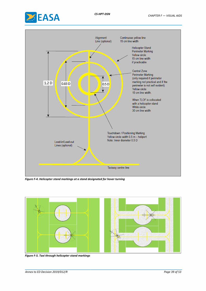
(1) A helicopter stand perimeter marking should be provided on a helicopter stand designed for turning. If a helicopter stand perimeter marking is not practicable, a central zone perimeter marking should be provided instead if the perimeter of the central zone is not self-evident.
(2) For a helicopter stand that is intended to be used for taxi-through and which does not allow a helicopter to turn, a stop line should be provided.
(3) Alignment lines and lead-in/lead-out lines should be provided on a helicopter stand (see Figures F-4 and F-5).
(b) Location:
(1) A helicopter stand perimeter marking on a helicopter stand designed for turning or, a central zone perimeter marking, should be concentric with the central zone of the stand.
(2) For a helicopter stand that is intended to be used for taxi-through and which does not allow the helicopter to turn, a stop line should be located on the helicopter ground taxiway axis at right angles to the centre line.
CS-HPT-DSN CHAPTER F — VISUAL AIDS
Annex to ED Decision 2019/012/R Page 39 of 53
Figure F-4. Helicopter stand markings at a stand designated for hover turning
Figure F-5. Taxi through helicopter stand markings
CS-HPT-DSN CHAPTER F — VISUAL AIDS
Annex to ED Decision 2019/012/R Page 40 of 53
(c) Characteristics:
(1) A helicopter stand perimeter marking should be a yellow circle and have a line width of 15 cm.
(2) A central zone perimeter marking should be a yellow circle and have a line width of 15 cm, except when the TLOF is collocated with a helicopter stand, in which case the characteristics of the TLOF perimeter markings should apply.
(3) For a helicopter stand that is intended to be used for taxi-through and which does not allow the helicopter to turn, the yellow stop line should not be less than the width of the helicopter ground taxiway and should have a line thickness of 50 cm.
(4) Alignment lines and lead-in/lead-out lines should be continuous yellow lines and should have a width of 15 cm.
(5) Curved portions of alignment lines and lead-in/lead-out lines should have radii appropriate to the most demanding helicopter type the helicopter stand is intended to serve.
(6) Stand identification markings should be marked in a contrasting colour so as to be easily readable.
(7) Where it is intended that helicopters proceed in one direction only, arrows indicating the direction to be followed may be added as part of the alignment lines.
GM1 HPT-DSN.F.610 Helicopter stand markings
Helicopter stand identification markings should be provided where there is a need to identify individual stands.
CS HPT-DSN.F.620 Flight path alignment guidance marking
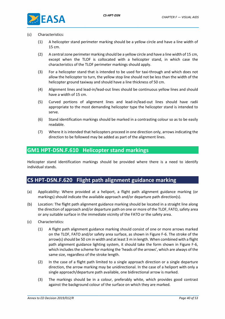
(a) Applicability: Where provided at a heliport, a flight path alignment guidance marking (or markings) should indicate the available approach and/or departure path direction(s).
(b) Location: The flight path alignment guidance marking should be located in a straight line along the direction of approach and/or departure path on one or more of the TLOF, FATO, safety area or any suitable surface in the immediate vicinity of the FATO or the safety area.
(c) Characteristics:
(1) A flight path alignment guidance marking should consist of one or more arrows marked on the TLOF, FATO and/or safety area surface, as shown in Figure F-6. The stroke of the arrow(s) should be 50 cm in width and at least 3 m in length. When combined with a flight path alignment guidance lighting system, it should take the form shown in Figure F-6, which includes the scheme for marking the ‘heads of the arrows’, which are always of the same size, regardless of the stroke length.
(2) In the case of a flight path limited to a single approach direction or a single departure direction, the arrow marking may be unidirectional. In the case of a heliport with only a single approach/departure path available, one bidirectional arrow is marked.
(3) The markings should be in a colour, preferably white, which provides good contrast against the background colour of the surface on which they are marked.
CS-HPT-DSN CHAPTER F — VISUAL AIDS
Annex to ED Decision 2019/012/R Page 41 of 53
Figure F-6. Flight path alignment guidance markings and lights
GM1 HPT-DSN.F.620 Flight path alignment guidance marking
Intentionally left blank
CS HPT-DSN.F.630 Approach lighting system
(a) Applicability: Where provided at a heliport, an approach lighting system should indicate a preferred approach direction.
(b) Location: The approach lighting system should be located in a straight line along the preferred direction of approach.
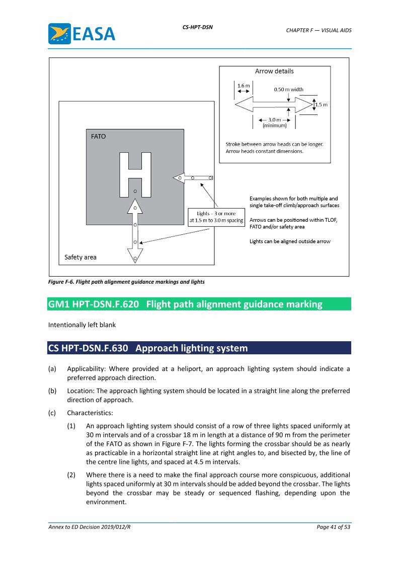
(c) Characteristics:
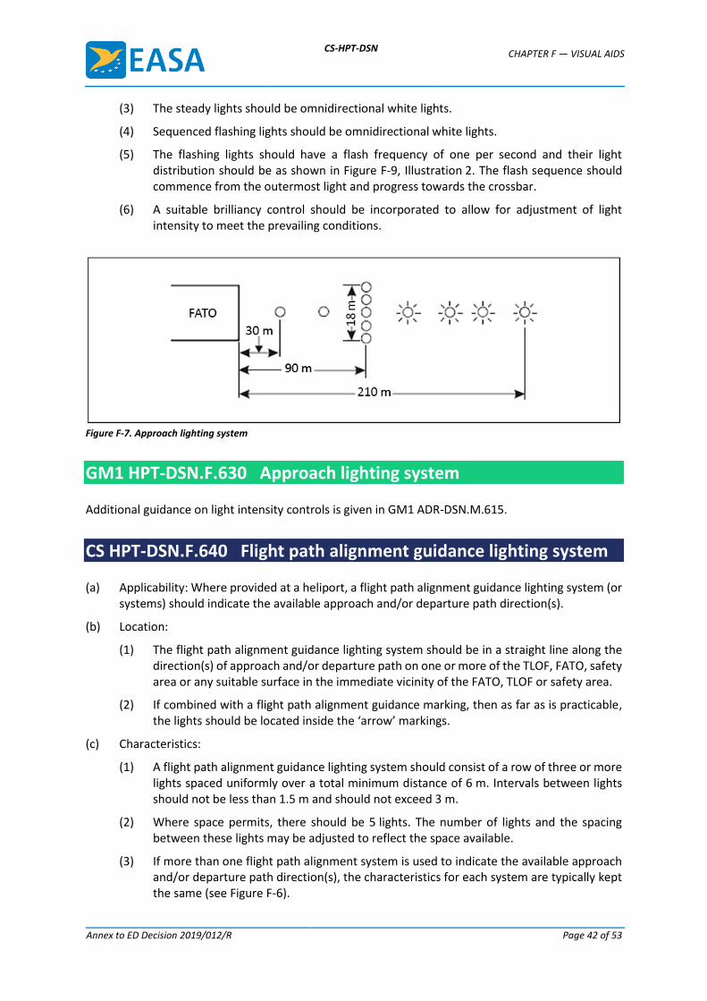
(1) An approach lighting system should consist of a row of three lights spaced uniformly at 30 m intervals and of a crossbar 18 m in length at a distance of 90 m from the perimeter of the FATO as shown in Figure F-7. The lights forming the crossbar should be as nearly as practicable in a horizontal straight line at right angles to, and bisected by, the line of the centre line lights, and spaced at 4.5 m intervals.
(2) Where there is a need to make the final approach course more conspicuous, additional lights spaced uniformly at 30 m intervals should be added beyond the crossbar. The lights beyond the crossbar may be steady or sequenced flashing, depending upon the environment.
CS-HPT-DSN CHAPTER F — VISUAL AIDS
Annex to ED Decision 2019/012/R Page 42 of 53
(3) The steady lights should be omnidirectional white lights.
(4) Sequenced flashing lights should be omnidirectional white lights.
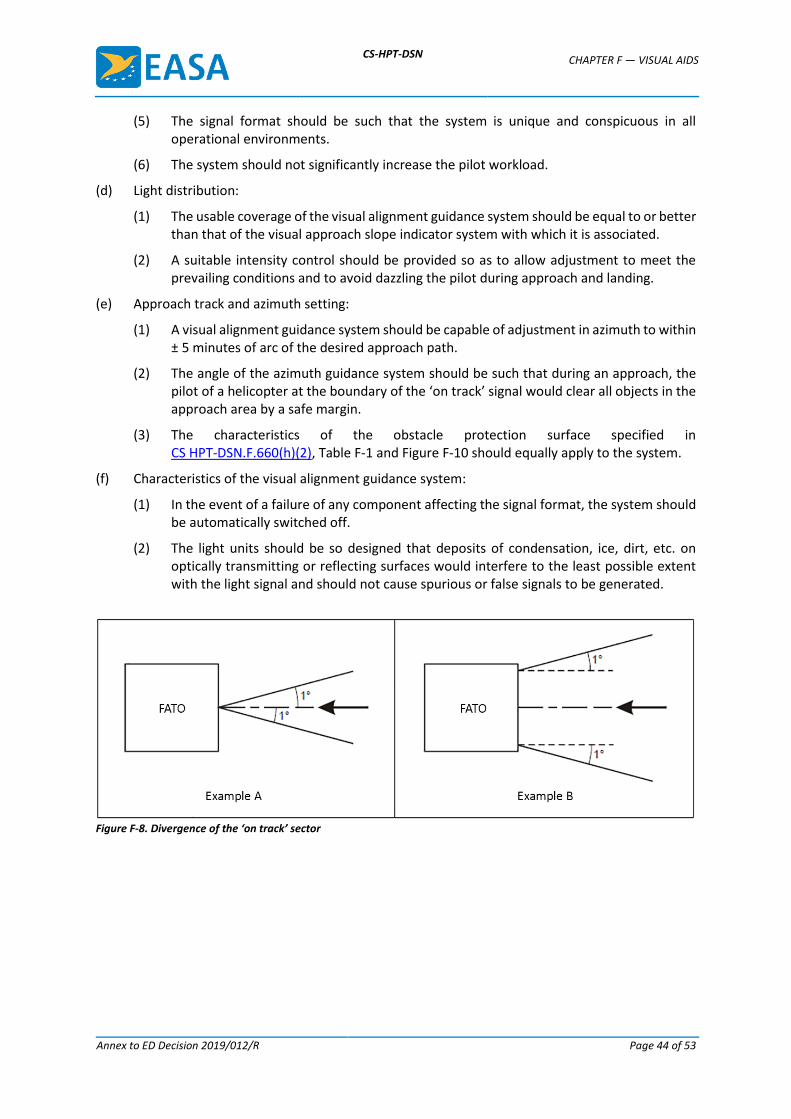
(5) The flashing lights should have a flash frequency of one per second and their light distribution should be as shown in Figure F-9, Illustration 2. The flash sequence should commence from the outermost light and progress towards the crossbar.
(6) A suitable brilliancy control should be incorporated to allow for adjustment of light intensity to meet the prevailing conditions.
Figure F-7. Approach lighting system
GM1 HPT-DSN.F.630 Approach lighting system
Additional guidance on light intensity controls is given in GM1 ADR-DSN.M.615.
CS HPT-DSN.F.640 Flight path alignment guidance lighting system
(a) Applicability: Where provided at a heliport, a flight path alignment guidance lighting system (or systems) should indicate the available approach and/or departure path direction(s).
(b) Location:
(1) The flight path alignment guidance lighting system should be in a straight line along the direction(s) of approach and/or departure path on one or more of the TLOF, FATO, safety area or any suitable surface in the immediate vicinity of the FATO, TLOF or safety area.
(2) If combined with a flight path alignment guidance marking, then as far as is practicable, the lights should be located inside the ‘arrow’ markings.
(c) Characteristics:
(1) A flight path alignment guidance lighting system should consist of a row of three or more lights spaced uniformly over a total minimum distance of 6 m. Intervals between lights should not be less than 1.5 m and should not exceed 3 m.
(2) Where space permits, there should be 5 lights. The number of lights and the spacing between these lights may be adjusted to reflect the space available.
(3) If more than one flight path alignment system is used to indicate the available approach and/or departure path direction(s), the characteristics for each system are typically kept the same (see Figure F-6).
CS-HPT-DSN CHAPTER F — VISUAL AIDS
Annex to ED Decision 2019/012/R Page 43 of 53
(4) The lights should be steady omnidirectional inset white lights.
(5) The distribution of the lights should be as indicated in Figure F-9, Illustration 5.
(6) A suitable control should be incorporated to allow for adjustment of light intensity to meet the prevailing conditions and to balance the flight path alignment guidance lighting system with other heliport lights and general lighting that may be present around the heliport.
GM1 HPT-DSN.F.640 Flight path alignment guidance lighting system
The flight path alignment guidance lighting can be combined with a flight path alignment guidance marking (or markings).
CS HPT-DSN.F.650 Visual alignment guidance system
(a) Applicability: Where provided at a heliport, a visual alignment guidance system should provide guidance to the pilot during the approach to a heliport.
(b) Location:
(1) The visual alignment guidance system should be located such that a helicopter is guided along the prescribed track towards the FATO.
(2) The system should be located at the downwind edge of the FATO and aligned along the preferred approach direction.
(3) The light units should be frangible and mounted as low as possible.
(4) Where the lights of the system need to be seen as discrete sources, light units should be located such that at the extremes of system coverage, the angle subtended between the units as seen by the pilot should not be less than 3 minutes of arc.
(5) The angles subtended between the light units of the system and other units of comparable or greater intensities should also be not less than 3 minutes of arc.
(6) The requirements of paragraphs (4) and (5) above can be met for lights on a line normal to the line of sight if the light units are separated by 1 m for every kilometre of viewing range.
(c) Signal format:
(1) The signal format of the alignment guidance system should include a minimum of three discrete signal sectors providing ‘offset to the right’, ‘on track’ and ‘offset to the left’ signals.
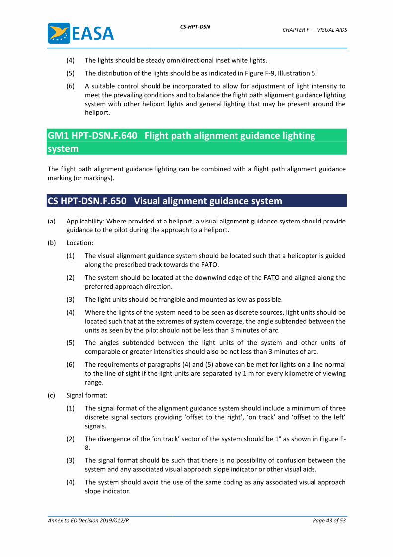
(2) The divergence of the ‘on track’ sector of the system should be 1° as shown in Figure F-8.
(3) The signal format should be such that there is no possibility of confusion between the system and any associated visual approach slope indicator or other visual aids.
(4) The system should avoid the use of the same coding as any associated visual approach slope indicator.
CS-HPT-DSN CHAPTER F — VISUAL AIDS
Annex to ED Decision 2019/012/R Page 44 of 53
(5) The signal format should be such that the system is unique and conspicuous in all operational environments.
(6) The system should not significantly increase the pilot workload.
(d) Light distribution:
(1) The usable coverage of the visual alignment guidance system should be equal to or better than that of the visual approach slope indicator system with which it is associated.
(2) A suitable intensity control should be provided so as to allow adjustment to meet the prevailing conditions and to avoid dazzling the pilot during approach and landing.
(e) Approach track and azimuth setting:
(1) A visual alignment guidance system should be capable of adjustment in azimuth to within ± 5 minutes of arc of the desired approach path.
(2) The angle of the azimuth guidance system should be such that during an approach, the pilot of a helicopter at the boundary of the ‘on track’ signal would clear all objects in the approach area by a safe margin.
(3) The characteristics of the obstacle protection surface specified in CS HPT-DSN.F.660(h)(2), Table F-1 and Figure F-10 should equally apply to the system.
(f) Characteristics of the visual alignment guidance system:
(1) In the event of a failure of any component affecting the signal format, the system should be automatically switched off.
(2) The light units should be so designed that deposits of condensation, ice, dirt, etc. on optically transmitting or reflecting surfaces would interfere to the least possible extent with the light signal and should not cause spurious or false signals to be generated.
Figure F-8. Divergence of the ‘on track’ sector
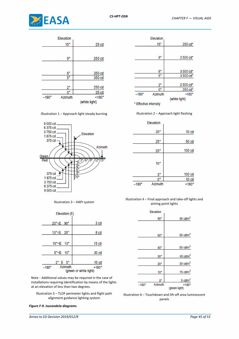
CS-HPT-DSN CHAPTER F — VISUAL AIDS
Annex to ED Decision 2019/012/R Page 45 of 53
Illustration 1 − Approach light steady burning
Illustration 2 − Approach light flashing
Illustration 3 − HAPI system
Illustration 4 − Final approach and take-off lights and aiming point lights
Note − Additional values may be required in the case of installations requiring identification by means of the lights at an elevation of less than two degrees.
Illustration 5 − TLOF perimeter lights and flight path alignment guidance lighting system
Illustration 6 − Touchdown and lift-off area luminescent
panels
Figure F-9. Isocandela diagrams
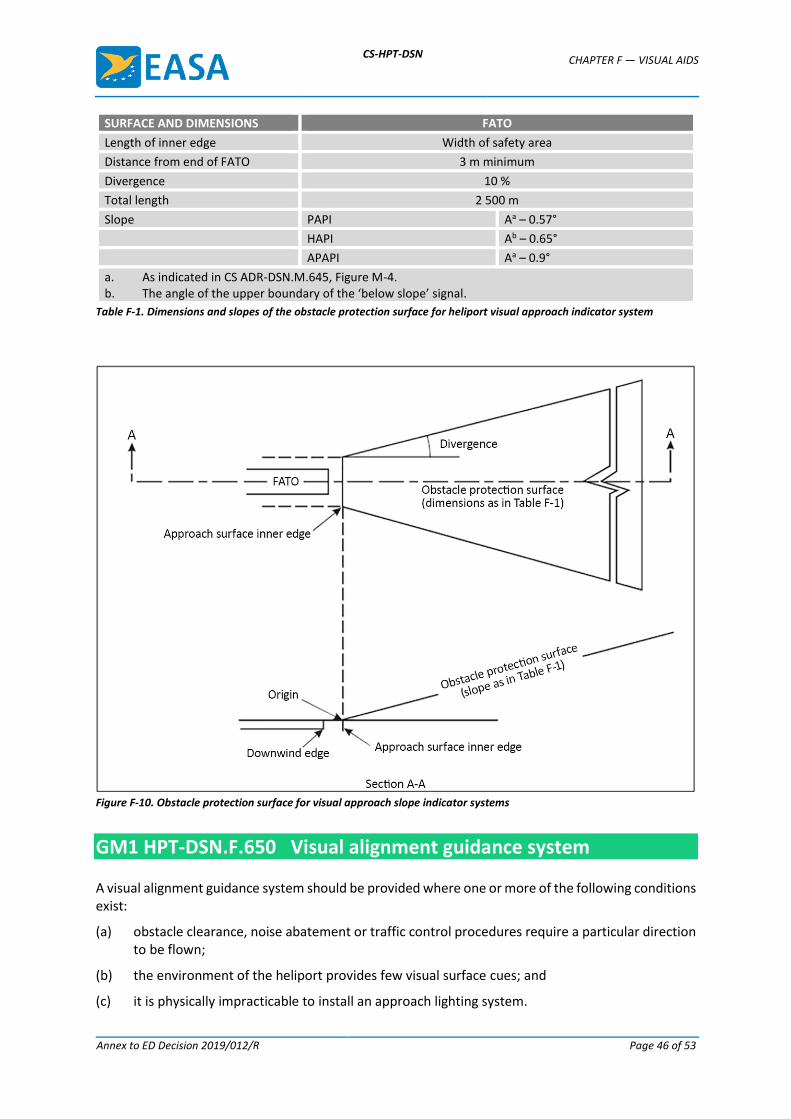
CS-HPT-DSN CHAPTER F — VISUAL AIDS
Annex to ED Decision 2019/012/R Page 46 of 53
SURFACE AND DIMENSIONS FATO
Length of inner edge Width of safety area
Distance from end of FATO 3 m minimum
Divergence 10 %
Total length 2 500 m
Slope PAPI Aa – 0.57°
HAPI Ab – 0.65°
APAPI Aa – 0.9°
a. As indicated in CS ADR-DSN.M.645, Figure M-4. b. The angle of the upper boundary of the ‘below slope’ signal.
Table F-1. Dimensions and slopes of the obstacle protection surface for heliport visual approach indicator system
Figure F-10. Obstacle protection surface for visual approach slope indicator systems
GM1 HPT-DSN.F.650 Visual alignment guidance system
A visual alignment guidance system should be provided where one or more of the following conditions exist:
(a) obstacle clearance, noise abatement or traffic control procedures require a particular direction to be flown;
(b) the environment of the heliport provides few visual surface cues; and
(c) it is physically impracticable to install an approach lighting system.
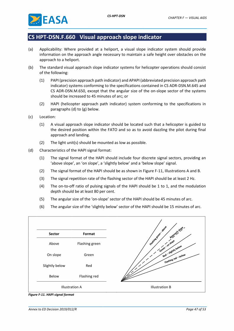
CS-HPT-DSN CHAPTER F — VISUAL AIDS
Annex to ED Decision 2019/012/R Page 47 of 53
CS HPT-DSN.F.660 Visual approach slope indicator
(a) Applicability: Where provided at a heliport, a visual slope indicator system should provide information on the approach angle necessary to maintain a safe height over obstacles on the approach to a heliport.
(b) The standard visual approach slope indicator systems for helicopter operations should consist of the following:
(1) PAPI (precision approach path indicator) and APAPI (abbreviated precision approach path indicator) systems conforming to the specifications contained in CS ADR-DSN.M.645 and CS ADR-DSN.M.650, except that the angular size of the on-slope sector of the systems should be increased to 45 minutes of arc; or
(2) HAPI (helicopter approach path indicator) system conforming to the specifications in paragraphs (d) to (g) below.
(c) Location:
(1) A visual approach slope indicator should be located such that a helicopter is guided to the desired position within the FATO and so as to avoid dazzling the pilot during final approach and landing.
(2) The light unit(s) should be mounted as low as possible.
(d) Characteristics of the HAPI signal format:
(1) The signal format of the HAPI should include four discrete signal sectors, providing an ‘above slope’, an ‘on slope’, a ‘slightly below’ and a ‘below slope’ signal.
(2) The signal format of the HAPI should be as shown in Figure F-11, Illustrations A and B.
(3) The signal repetition rate of the flashing sector of the HAPI should be at least 2 Hz.
(4) The on-to-off ratio of pulsing signals of the HAPI should be 1 to 1, and the modulation depth should be at least 80 per cent.
(5) The angular size of the ‘on-slope’ sector of the HAPI should be 45 minutes of arc.
(6) The angular size of the ‘slightly below’ sector of the HAPI should be 15 minutes of arc.
Sector Format
Above Flashing green
On slope Green
Slightly below Red
Below Flashing red
Illustration A Illustration B
Figure F-11. HAPI signal format
CS-HPT-DSN CHAPTER F — VISUAL AIDS
Annex to ED Decision 2019/012/R Page 48 of 53
(e) Light distribution:
(1) The light intensity distribution of the HAPI in red and green colours should be as shown in Figure F-9, Illustration 3.
(2) The colour transition of the HAPI in the vertical plane should be such as to appear to an observer at a distance of not less than 300 m to occur within a vertical angle of not more than three minutes of arc.
(3) The transmission factor of a red or green filter should be not less than 15 per cent at the maximum intensity setting.
(4) At full intensity, the red light of the HAPI should have a Y-coordinate not exceeding 0.320, and the green light should be within the boundaries specified in CS ADR-DSN.U.930(b).
(5) A suitable intensity control should be provided so as to allow adjustment to meet the prevailing conditions and to avoid dazzling the pilot during approach and landing.
(f) Approach slope and elevation setting:
(1) A HAPI system should be capable of adjustment in elevation at any desired angle between 1 degree and 12 degrees above the horizontal with an accuracy of ± 5 minutes of arc.
(2) The angle of elevation setting of a HAPI should be such that during an approach, the pilot of a helicopter observing the upper boundary of the ‘below slope’ signal would clear all objects in the approach area by a safe margin.
(g) Characteristics of the light unit:
(1) The system should be so designed that:
(i) in the event the vertical misalignment of a unit exceeds ± 0.5 degrees (± 30 minutes), the system should switch off automatically; and
(ii) if the flashing mechanism fails, no light is emitted in the failed flashing sector(s).
(2) The light unit of the HAPI should be so designed that deposits of condensation, ice, dirt, etc. on optically transmitting or reflecting surfaces would interfere to the least possible extent with the light signal and should not cause spurious or false signals to be generated.
(h) Obstacle protection surface (applicable to PAPI, APAPI and HAPI):
(1) An obstacle protection surface should be established when it is intended to provide a visual approach slope indicator system.
(2) The characteristics of the obstacle protection surface, i.e. origin, divergence, length and slope, should correspond to those specified in the relevant column of Table F-1 and in Figure F-10.
(3) New objects or extensions of existing objects should not be permitted above an obstacle protection surface except when the new object or extension would be shielded by an existing immovable object.
(4) Existing objects above an obstacle protection surface should be removed except when the object is shielded by an existing immovable object, or when after a safety assessment, it is determined that the object would not adversely affect the safety of operations of helicopters.
(5) Where a safety assessment indicates that an existing object extending above an obstacle protection surface could adversely affect the safety of operations of helicopters, one or more of the following measures should be taken:
CS-HPT-DSN CHAPTER F — VISUAL AIDS
Annex to ED Decision 2019/012/R Page 49 of 53
(i) suitably raise the approach slope of the system;
(ii) reduce the azimuth spread of the system so that the object is outside the confines of the beam;
(iii) displace the axis of the system and its associated obstacle protection surface by no more than 5 degrees;
(iv) suitably displace the FATO; and
(v) install a visual alignment guidance system.
GM1 HPT-DSN.F.660 Visual approach slope indicator
(a) A visual approach slope indicator should be provided for a heliport where one or more of the following conditions exist:
(1) obstacle clearance, noise abatement or traffic control procedures require a particular slope to be flown;
(2) the environment of the heliport provides few visual surface cues; and
(3) the characteristics of the helicopter require a stabilised approach.
(b) When more than one visual approach slope indicator is installed at an aerodrome (e.g. PAPI, APAPI), a visual approach slope indicator should be designed and calibrated in order to give a clear and unambiguous indication to helicopter pilots approaching to land.
(c) A heliport visual approach slope indicator should be located adjacent to the nominal aiming point and aligned in azimuth with the preferred approach direction.
(d) Care is required in the design of the unit to minimise spurious signals between the signal sectors, and at the azimuth coverage limits.
(e) Larger azimuth coverage can be obtained by installing the HAPI system on a turntable.
CS HPT-DSN.F.670 Final approach and take-off area lighting systems
(a) Applicability: FATO lights should be provided where a FATO is established at a heliport intended for use at night. They can be omitted where the FATO and the TLOF are nearly coincidental and the TLOF lights are provided, or the extent of the FATO is self-evident.
(b) Location: FATO lights should be placed along the edges of the FATO. The lights should be uniformly spaced as follows:
(1) for an area in the form of a square or rectangle, at intervals of not more than 50 m with a minimum of four lights on each side including a light at each corner; and
(2) for any other shaped area, including a circular area, at intervals of not more than 5 m with a minimum of ten lights.
(c) Characteristics:
(1) FATO lights should be fixed omnidirectional lights showing white. Where the intensity of the lights is to be varied, the lights should show variable white.
(2) The light distribution of FATO lights should be as shown in Figure F-9, Illustration 4.
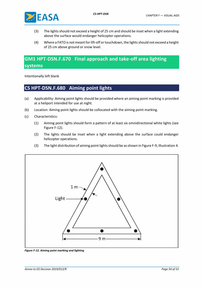
CS-HPT-DSN CHAPTER F — VISUAL AIDS
Annex to ED Decision 2019/012/R Page 50 of 53
(3) The lights should not exceed a height of 25 cm and should be inset when a light extending above the surface would endanger helicopter operations.
(4) Where a FATO is not meant for lift-off or touchdown, the lights should not exceed a height of 25 cm above ground or snow level.
GM1 HPT-DSN.F.670 Final approach and take-off area lighting systems
Intentionally left blank
CS HPT-DSN.F.680 Aiming point lights
(a) Applicability: Aiming point lights should be provided where an aiming point marking is provided at a heliport intended for use at night.
(b) Location: Aiming point lights should be collocated with the aiming point marking.
(c) Characteristics:
(1) Aiming point lights should form a pattern of at least six omnidirectional white lights (see Figure F-12).
(2) The lights should be inset when a light extending above the surface could endanger helicopter operations.
(3) The light distribution of aiming point lights should be as shown in Figure F-9, Illustration 4.
Figure F-12. Aiming point marking and lighting
CS-HPT-DSN CHAPTER F — VISUAL AIDS
Annex to ED Decision 2019/012/R Page 51 of 53
GM1 HPT-DSN.F.680 Aiming point lights
Intentionally left blank
CS HPT-DSN.F.690 Touchdown and lift-off area lighting system
(a) Applicability:
(1) A TLOF lighting system should be provided at a heliport intended for use at night.
(2) The TLOF lighting system for a heliport should consist of one or more of the following:
(i) perimeter lights; or
(ii) floodlighting; or
(iii) ASPSL or LP lighting to identify the TLOF when (i) and (ii) are not practicable and FATO lights are available.
(b) Location:
(1) TLOF perimeter lights should be placed along the edge of the area designated for use as the TLOF or within a distance of 1.5 m from the edge.
(2) Where the TLOF is a circle, the lights should be:
(i) located on straight lines in a pattern which should provide information to pilots on drift displacement; or
(ii) evenly spaced around the perimeter of the TLOF at the appropriate intervals, sufficient to present the pattern, except that over a sector of 45 degrees, the lights should be spaced at half spacing.
(3) TLOF perimeter lights should be uniformly spaced at intervals of not more than 5 m.
(4) Where TLOF perimeter lights are located on straight lines, there should be a minimum number of four lights on each side, including a light at each corner.
(5) For a circular TLOF, where lights are installed in accordance with paragraph (2)(ii) above, there should be a minimum of fourteen lights.
(6) Where ASPSL or LPs are provided to identify the TLOF, which is not a circle, they should be placed along the marking designating the edge of the TLOF.
(7) Where ASPL or LPs are provided to identify the TLOF, which is a circle, they should be located on straight lines circumscribing the area.
(8) The minimum number of LPs on a TLOF should be nine.
(9) The total length of LPs in a pattern should not be less than 50 per cent of the length of the pattern.
(10) There should be an odd number of LPs with a minimum number of three panels on each side of the TLOF, including a panel at each corner.
(11) LPs should be uniformly spaced with a distance between adjacent panel ends of not more than 5 m on each side of the TLOF.
(12) TLOF floodlights should be located so as to avoid glare to pilots in flight or to personnel working on the area.
CS-HPT-DSN CHAPTER F — VISUAL AIDS
Annex to ED Decision 2019/012/R Page 52 of 53
(13) The arrangement and aiming of floodlights should be such that shadows are kept to a minimum.
(c) Characteristics:
(1) The TLOF perimeter lights should be fixed omnidirectional lights showing green.
(2) ASPSL or LPs should emit green light when used to define the perimeter of the TLOF.
(3) The chromaticity and luminance of colours of LPs should be in accordance with the specifications in CS ADR-DSN.U.935.
(4) An LP should have a minimum width of 6 cm. The panel housing should be the same colour as the marking it defines.
(5) The perimeter lights should not exceed a height of 25 cm and should be inset when a light extending above the surface could endanger helicopter operations.
(6) When located within the safety area of a heliport, the TLOF floodlights should not exceed a height of 25 cm.
(7) The LPs should not extend above the surface by more than 2.5 cm.
(8) The light distribution of the perimeter lights should be as shown in Figure F-9, Illustration 5.
(9) The light distribution of the LPs should be as shown in Figure F-9, Illustration 6.
(10) The spectral distribution of TLOF area floodlights should be such that the surface and obstacle marking can be correctly identified.
(11) The average horizontal illuminance of the floodlighting should be at least 10 lux, with a uniformity ratio (average to minimum) of not more than 8:1 measured on the surface of the TLOF.
(12) The lighting used to identify the touchdown marking should comprise a segmented circle of omnidirectional ASPSL strips showing yellow. The segments should consist of ASPSL strips, and the total length of the ASPSL strips should not be less than 50 per cent of the circumference of the circle.
(13) If utilised, the heliport identification marking lighting should be omnidirectional showing green.
GM1 HPT-DSN.F.690 Touchdown and lift-off area lighting system
TLOF ASPSL and/or LPs to identify the touchdown marking and/or floodlighting should be provided for use at night when enhanced surface texture cues are required.
CS HPT-DSN.F.700 Taxiway lights
The specifications of CS ADR-DSN.M.710, CS ADR-DSN.M.715 and CS ADR-DSN.M.720 are applicable to taxiways intended for ground taxiing of helicopters.
GM1 HPT-DSN.F.700 Taxiway lights
Intentionally left blank
CS-HPT-DSN CHAPTER F — VISUAL AIDS
Annex to ED Decision 2019/012/R Page 53 of 53
CS HPT-DSN.F.710 Visual aids for denoting obstacles
Obstacles should be marked and lit in accordance with CS ADR-DSN.Q.840, CS ADR-DSN.Q.845 and CS ADR-DSN.Q.850.
GM1 HPT-DSN.F.710 Visual aids for denoting obstacles
(a) General: If it is not possible to display obstacle lights on obstacles at a heliport intended for use at night, the obstacles should be floodlit.
(b) Location: Obstacle floodlights should be arranged so as to illuminate the entire obstacle and, as far as practicable, in a manner so as not to dazzle helicopter pilots.
(c) Characteristics: Obstacle floodlighting should produce a luminance of at least 10 cd/m2.
Related Documents


