HF Thermoplastic Centrifugal Fans

Welcome message from author
This document is posted to help you gain knowledge. Please leave a comment to let me know what you think about it! Share it to your friends and learn new things together.
Transcript

HF ThermoplasticCentrifugal Fans
HF Thermoplastic Centrifugal Fans1
HF-centrifugal fans are ideally suitable for extraction ofexhaust air and gases. These fans are used mainly forextraction of corrosive fumes in such applications as:
• Electroplating and Metal Finishing• Circuit Board Manufacturing• Chemical Processing• Pulp and Paper• Water and Waste Water Treatment• Industrial, Government & Educational Laboratories• Hospitals• Pharmaceutical
They are available with direct drive (design shape D) orbelt drive (design shape R).
HF-centrifugal fans are produced in sizes from 3 to 20inches or 75 to 500 mm.
Depending on thee impeller sizes (15 or 17) flow ratescan range from 20 to 7000 CFM or 34 to 11,800 m3/hat a maximum static pressure of 6.5 inches of W.G or1600 PA.
A fan efficiency of 81% is attainable at the optimumoperating point. Greater air performance is achievablewith the HF R... 13 D/R series fan ranging in sizes 20 to40 inched (500 to 1000 mm) in three pressure stages.Performance rates range from 1800 to 88,000 CFM(3000 to 150,000 m3/h at a maximum total static pressureof 12 inches [3000PA]). The pressure stage isdifferentiated through the circumferential of the impeller.
HousingThe HF series of fan housings in generally made fromrotationally moulded flame and UV retardant polyethylene(PEs). Other thermoplastic materials are available uponrequest.
The housing is fitted with a splinter guard around thecircumference. A condensate drain is installed at thelowest point of the housing.
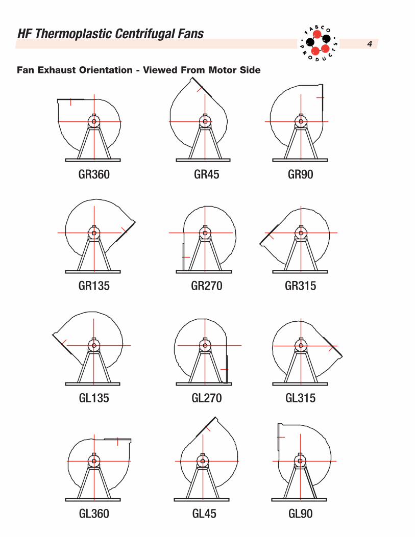
HF fans are normally produced in an upblast position andcapable of rotating the exhaust outlet in steps of 45º. Thenormal position is either refered to as GR 360 or GL 360.The exhaust outlet may be connected via a flexibleconnector of flange outlet. Since the outlet is round;attachment to round ducting does not require a transitionfitting.
ImpellerThe impeller is made of flame retardant polypropylene(PPs) that is balanced both statically and dynamically. Inthe case of a direct drive fan the impeller is secured tothe motor shaft by means of a taper lock bushing. Onbelt drive fans the impeller is secured in the same way(taper lock bushing) to the drive shaft and supported byflanged double bearings.
The impeller can be removed without having to dismantlethe housing from the frame.
The fan is mounted to a welded steel frame that is hotdip galvanized.
Accessories:• Flexible vibration connectors• Inlet & outlet flanges• Neoprene or spring vibration isolators• Shaft seal• Inspection port• Weather cover• Starter & disconnect switches• Variable frequency drive
HF-Centrifugal Fans
HF Thermoplastic Centrifugal Fans2
HF-fans are suitable for exhausting agressive corrosivefumes or humid air. Explosive atmosphere can bedelivered with HF-fans especially designed for thispurpose. The permissible gas temperatures for plasticsmost frequently used in our fans are generally:
• For PVC: 0 °C up to 50 °C• For PE, PE-FR (PEs) -20 °C up to 60 °C• For PP, PP-FR (PPs): 0 °C up to 70 °C • And for PVDF, GRP, and CRP: -10 °C up to 100 °C
These temperature ranges must be reviewed and ifnecessary limited depending upon gas composition andimpeller’s rotational speed. In case of exceptionallyaggressive media, the reduction must be reviewed anddetermined from case to case.Our data sheets containinformation about mechanical limits. Other applications ordesign changes must be implemented in consultationwith the manufacturer.
Rough assessment of chemical resistance can be madeaccording to the following instructions:
Chemical resistance of materials used can be derivedfrom the material manufacturers. In case of critical gasmedia, please inquire in writing giving all the conditions ofthe application.
Material Data
Material Resistant to Not resistant to
PVC, PVDF
Acids, caustic soda,alcohol, aliphatic
hydrocarbons, mineraland plant oil-extracts
Aromatic and chlorinatedhydrocarbons, ester
and ketone
PP, PP-FR (PPs)and PE, PE-FR (PEs)
Acids, caustic soda, saltsolutions, oil and diluted
solvents
Oxidizing acidsand halogens
GRP, CRP
Diluted acids, dilutedcaustic soda, alcohol,
benzene, petrol, oiland solvents
Concentrated acids,concentrated caustic soda,
ammonia, acetone,ester and ketone
Model
HF R A F
Roof
Axial
Radial
Nominal InletDiameter
125 to 1000 mm
For radial fans -10fold the O.D. of impeller
to suction diameter(e.g. 13 up to 17 & 48)
125 mm (5˝)to
500 mm (20˝)
Impeller Series-------------
560 mm (22˝)to
1000 mm (39˝)
HF
HF
HF
R
R
Fan Type Size Series Type of Drive
D R
D or R
D or R
15 - 17
13
Belt
Direct
Clarification of Fan Type Designations
PP = PolypropylenePP-FR (PPs) = Polypropylene flame retardantPE = PolyethylenePE-FR (PEs) = Polyethylene flame retardant
PVC = Polyvinyl chloridePVDF = Polyvinylidene fluorideGRP = Glass fibre reinforced plasticCRP = Carbon fibre reinforced plastic
Explanation of code designations:

HF Thermoplastic Centrifugal Fans3
HousingRotationally moulded Polyethylene (PE’s) that is bothflame retardant and UV inhibited as standard. Additionalthermoplastic materials are available to suit mostapplications. A condensate drain is provided at thebottom point of the fan housing. The housing is mountedwithin a rigid hot dipped galvanized frame.
All sizes are available in clockwise or counter clockwiserotations as well as six standard discharge positions.
ImpellerInjection moulded Polypropylene (PPs) flame retardantimpeller, statically and dynamically balanced and keyedto the fan shaft. In the case of direct drive, the impeller issecured directly on the motor shaft by means of a taperlock bushing. With belt drive, the impeller is secured in
the same way on a steel shaft, supported by flangeddouble bearings and ball bearings. The impeller can beremoved without first having to dismantle the housing.
Inlet/OutletBoth inlet and outlet diameters are the same sizes forease of installation of adjacent duct work. In addition fanscan be fitted with optional inlet and outlet flanges.
Drive ArrangementsArrangement 4 – Direct DriveArrangement 9 – Belt Drive
MotorsSupplied as high efficiency TEFC motors. Explosion andmill & chemical service rated motors are optional.
Standard Construction Features
Vibration IsolatorsAll HF fans are design to accommodate vibration isolatorsin either neoprene pads or housed spring units.
Flexible Vibration ConnectorsHeavy-duty polyvinyl chloride (PVC) is available.
Inlet/Outlet FlangesWhere applications require tight bolted duct connections.Flanges are available with or without prepunched holes.
Shaft SealsTo limit the air leakage around the housing shaft passage,a felt ring is standard construction. For more stringentapplications other shaft seal options are available.
Access/Inspection PortAll HF fans can be provided with an access port, whichallows for examination and cleaning of the housing interiorwithout disassembly, resulting in less downtime.
Weather CoverFor outside installation a motor covering hood is available.
Starter & Disconnect SwitchesA wide assortment of both enclosed starters / disconnectsfrom Nema 1 to corrosion resistant boxes are available.
Variable Frequency DrivesA wide assortment of VFD’s is available to meet bothmotor capability and application.
Accessories
HF Thermoplastic Centrifugal Fans4
Fan Exhaust Orientation - Viewed From Motor Side
GR360 GR45 GR90
GR135 GR270 GR315
GL135 GL270 GL315
GL90GL360 GL45
HF Thermoplastic Centrifugal Fans5
Products not manufactured by Fabco carry the originalmanufacturer’s warranty. (Copies on request)
All products manufactured by Fabco will be free fromdefects in material and workmanship for a period of one(1) year from date of shipment.
If any product is found unsatisfactory under this warranty,the purchaser should notify Fabco in writing and, afterreceipt of our shipping approval, the purchaser mayreturn the product to our facility, transportation prepaid.Such products will be inspected by us and, if determineddefective due to material or workmanship, shall bereplaced or put in proper operating condition, free of allcharges except transportation.
The correction of any defects by repair or replacement byFabco shall constitute fulfillment of all obligations andliability of ours.
We are not responsible for damages to Fabco productsthrough improper installation, maintenance, use, or attemptsto operate it beyond its mechanical or electrical capacity
intentionally or otherwise, or for unauthorized repair.
Any failure to notify us of unsatisfactory operation, or anyimproper or unauthorized installation, maintenance, use,repair, or adjustments, shall terminate this warranty andshall relieve Fabco from any further responsibilitythereunder.
Fabco shall not be liable for special or consequentialdamages in any claim, action, suit, or proceedings arisingunder this warranty, nor shall there be any liabilitythereunder for claims of labour, loss of profit or goodwill,repairs or other expenses incidental to replacement.
All information, recommendations and suggestions,appearing in this catalogue are based upon tests anddata believed to be reliable; however, it is the user’sresponsibility to determine the suitability of our productsfor each application.
The Product Warranty expressed above is our soleWarranty. No other warranties, whether verbal,expressed, or implied, are applicable.
In case of centrifugal fans, the medium is entering theimpeller axially through ducting, a suction box or directlyfrom outside. The impeller is equipped with six bladesbeing bent backward, thus deviating the medium to radialdirection. The conversion from flow energy into staticpressure is effected to a great extent in the impeller.
The standard execution of this high-efficiency impeller ismade of PPs, and the transmission of the torque iseffected by means of a steel hub being mounted in theimpeller and being protected against corrosion. Eachimpeller is balanced electro-dynamically in two levels,balancing quality Q 6.3, according to VDI 2060.
The plastic housing is provided to bring the mediumtogether and to drain it. It is dimensioned according tothe required nominal pressure rates. The standardhousing is equipped with a condensate drain beinglocated at the lowest point, which can be connected toa discharge pipe in case of excessive formation ofcondensate. The suction nozzle is fastened by screws,and thus can be easily removed. A gasket is inserted inthe nozzle and at the back panel of the housing. Thehousing is fastened to the base frame.
The base frame (rack) is made of hot dip galvanized steel.Predrilled holes are prepared to fasten the vibration
absorbers. The vibration absorbing elements reduce thetransmission of the dynamic load to the substructure.
The standard fans can be delivered in two executions.
Design D Direct Drive. The impeller is fastened directlyat the motor shaft. The standard motor is ahigh efficiency TEFC.
Design R Belt Drive. The drive is affected by V-belts.The impeller is fastened on a steel shaft of aflange-type double bearing. The standardmotor is a high efficiency TEFC. A shaft/beltguard consists of PVC or PP material.
The plasticized PVC flexible connectors are available toprevent the transmission of vibrations from the fan to theducting. They are fastened at the fan by means of a bandclamp fitting of stainless steel.
The weather-protection hood of plastic material or steelabove the drive is recommended in case of an outdoorinstallation of the fan.
An inspection/access port is available for observation andeasy cleaning of the impeller.
1. Warranty
2. Design and Features

HF Thermoplastic Centrifugal Fans6
All shipments are F.O.B. shipping point except whereotherwise stated. The term F.O.B. shipping point meansthe carrier accepts all responsibility upon accepting theshipment at Fabco’s facility. Thus any claims must besettled between the buyer and the carrier.
All centrifugal fans are shipped crated to minimizedamage during shipment.
Upon receipt of shipment, all goods are to be checkedfor damages and for missing parts using the shippingdocuments. Please inform the manufacturer immediatelyin case of any discrepancies or concerns.
The fan should never be lifted by the shaft, housing,motor, belt guard or accessories.
Prior to installation the fan is to be checked that all looseparts are secured and if the impeller can be turned easily.
Critical to every fan installation is a strong, levelfoundation. Reinforced poured concrete provides anexcellent foundation and is used in most installations.Steel beams are also acceptable, but must be sturdyenough, with welded construction, to prevent flexing andvibration.
To eliminate vibration and noise from being transferred tothe building, vibration isolators should be used. The typesof vibration isolators currently available are: elastomer,shearmount, compression mount, ribbed neoprene andcork, natural cork and metal springs. Consult theappropriate isolator catalog for specific applications.
The isolators are installed between the isolation base andthe concrete or steel foundation. The fan is mounteddirectly on the isolation base and must be supported theentire length of the fan base angle.
After the fan, isolator base and isolators are installed, theentire assembly must be leveled. Position the level on theisolation base, not the fan shaft, for proper leveling.Additionally, the motor and fan shafts must be level andparallel relative to each other for proper alignment.
The fans are to be connected to the ducting on thesuction and the pressure side using the elastic collars.The plastic drain plug at the condensate drain is to beremoved.
According to the IEC standard 34-1, the standard motorsbeing supplied are designed for normal operatingconditions. The ambient temperature should not exceed+40 °C, the installation height should be below 1000 m,and the atmospheric pressure should not exceed 1050hPa. If the motor has been designed for deviatingspecifications, it is stated on the nameplate of the motorand/or in our order confirmation. The cooling air supplyshould not be hindered.
UNIT IDENTIFICATIONThe tag below is an example of an identification label onthe fan. The information provides general details aboutthe fan, as well as containing specific information uniqueto the unit. When contacting your Fabco representativewith future needs or questions, please have theinformation on this label available
3. Transport and Installation
Fabco HF Fan
Type:
Serial:
Flow: CFM
Static Pressure: inches of W.G.
RPM: 1/min HP
RPM max: 1/min � %
Density: kgm3 temp max ºC
HF Thermoplastic Centrifugal Fans7
Prior to starting the unit, the capacity rates of the motorare to be compared with the available power supply andmains frequency. The power supply cable should beprotected from damage and should be dimensionedaccording to the power consumption.
The access to the electric motor is only allowed when thepower supply had been cut-off, locked out and under dryambient conditions.
Connection and location of the clamping saddles is to beeffected according to the wiring diagram being located inthe terminal box. Each motor should always be protectedby a motor disconnect switch.
The protective motor switches are not included in ourstandard delivery scope.
The electric connection must be performed by qualifiedpersonnel. Prior to the trial run, all rotating parts are to beprotected according to the regulations for prevention ofaccidents to avoid unintentional contact. The motor is tobe switched-on for a short time, and the rotation of thefan is to be checked. The rotation should correspond tothe direction sign attached at the housing.
On each new connection, the rotation is to be checked.During the starting phase, the current consumption ratemay be six to eight times higher than the nominal currentbeing indicated on the motor nameplate. At nominal
speed, that rate should not exceed the nominal currentrate. The motors are always designed for the operatingspeed being indicated on the nameplate. The maximumload of the motors is the current value multiplied by 1.5for two minutes.
Radial fans with a motor capacity greater than or equal to4 kW should be started with a star connected threephase system, and the operation should be continuedwith a delta connection. Should the connection time ofthe star connected three phase system be not sufficientto start the fan, the starting phase can be extended byinstallation of a time lag relay. A better solution would beto start by means of a suitable frequency converter.
Depending on design and operating stress, measuresshould be taken to avoid a deposit of solid matter on theimpeller and the housing. Ensure that the impeller isnever out-of-balance, otherwise it will sustain damage.The fan is to be protected in a suitable way to avoidingestion of foreign matter. Installation of protectiondevices is to be accomplished in such a way that easyaccess for performance and condition checks is ensured.According to the UVV regulations, the fans should beequipped with a splinter guard (plasticized PVC collar orgrid around the housing).
Check all screwed connections and retighten them, ifrequired.
4. Start-up
HF Thermoplastic Centrifugal Fans8
The maintenance intervals are dependent on the natureand composition of the medium to be exhausted and thefan used (direct drive or belt drive). While themaintenance interval for fume cupboards may be severalyears, exhausting of a pickling bath requires amaintenance interval of only one week. The maintenanceinterval required is to be determined via several checksduring the initial phase.
Prior to any cleaning or maintenance tasks, the fan is tobe switched-off and to be protected from unauthorizedstart-up. Make sure, that the impeller comes to acomplete stop. The regulations for prevention ofaccidents are to be observed. Only qualified personnelshould perform maintenance tasks.
Check the fan periodically for smooth running. Should itbe running rough, it may require cleaning andrebalancing. Cleaning of the fan should be effected byrinsing or by careful mechanical removal of the impurities.Should there be any damage to the impeller, themanufacturer is to be consulted immediately.
Maintenance of the motor is to be performed accordingto the instructions of the motor manufacturer.
The flange-type double bearings are maintenance-free.The grease filling of the sealed deep groove ball bearingsis sufficient for lifetime and corresponds to a calculatedlifetime of approx. 20000 to 30000 operating hours. Themaximum admissible storage temperature should be90 °C during standstill, and 70 °C during operation.
The main reason for abnormal heating of the bearings,excessive vibration and fan noise is insufficient V-belttensioning. Consequently, belt tension is to be checkedparticularly during the first weeks and should beadjusted, if required.
This is particularly important, if the fan has not been usedfor an extended period or if the start-up of the fan is at alater date. Insufficient tension will result in slipping andincreased wear. Over tensioning of the V-belts results indamaged bearings.
Prior to checking the V-belt tension or prior to areplacement of the V-belts, the fan is to be protectedfrom unintentional adjustment.
When replacing V-belts, ensure that the shafts andpulleys are in true alignment. The groove profile shouldbe exact and the grooves should be clean.
The axis distance is to be reduced sufficiently prior toinsertion. In case of series HF R, this is done byadjustment of the retaining plate of the motor. The V-beltsare to be inserted separately by hand into the grooves.Never insert the V-belts over the pulley, since this willresult in damage of the belts. The V-belts are to betensioned and, if required, to be checked andretensioned after 1 to 4 operating hours.
5.1 How to Remove the Impeller • Disconnect the motor (6).• Loosen the fastening screws of the air intake fitting
(2.1) and withdraw the air intake fitting.• Unscrew the screw cap (3.7) by hand and remove
the cap (3.3).• Loosen the taper-lock clamping bushing (3.1) by
unscrewing the two hexagon socket screws. Oneof the screws is to be screwed into the boreholefor forcing screws by half of the thread, and it is tobe tightened. The screw is to be tightened evenlyuntil the bushing can be loosened from the hub.
• Remove the impeller from the shaft journal.
5.2 How to Remove the Motor in Direct Drive • Disconnect the motor (6).• Remove the impeller (as described above).• Loosen the fastening screws of the fan housing (2)
at the frame (4) and remove the housing.• Loosen the fastening screws of the motor and
remove the motor.
5.3 How to Remove the Motor in Belt Drive • Disconnect the motor. • Remove the belt guard box (11.1), and loosen
the fastening screws of the lower protectioncover (11.2).
• Loosen the fastening claw and remove the V-belt.• Withdraw the Taper-Lock‚ spare clamping bush
(see above) and the V-belt pulley (10) from themotor shaft.
• Loosen the fastening screws of the motor andremove the motor.
5.4 How to Remove the Flange-type Double Bearing• Disconnect the motor. • Remove the belt guard box, and loosen the
fastening screws of the lower protectioncover (plate).
• Loosen the fastening claw and remove the V-belt.• Remove the impeller.• Remove the fan housing.• Loosen the screws of the flange bearing (8) and
remove the bearing unit.
5. Maintenance

HF Thermoplastic Centrifugal Fans9
This technical documentation is provided to help ensureperfect and continuous operation. In case of queries orcomplaints, please contact our sales department.
Since the HF series of centrifugal fans were designed foreasy serviceability only proprietary parts (i.e. housings,impeller systems, taper lock bushings, double flangebearings, guards) will be inventoried at Fabco.
Fabco does not accept any liability or warranty fordamages resulting from the use of other than originalspare-parts and accessories.
In case of spare-part orders, please state the following data:• Order number• Type • Designation of the spare-part • Quantity
7. Spare Parts
6. RepairIn case of any fan failure during operation, we recommend that you review the trouble shooting guide below.
Please observe that inappropriate installation and start-up will result in a considerable performance loss, or the fan willbe even damaged completely.
Rough running of fan Impeller out of balance
Caking at the impeller
Material decomposition at the impeller due to aggressive media
Deformation of the impeller due to excessive temperature
Incorrect alignment of V-belt drive
Rebalance by specialized company
Clean carefully, rebalance if required
Consult the manufacturer
Replace impeller, consult the manufacturer, check bearing
Replace V-belts by set
V-belt broken or damaged Normal wear
Excessive initial tension of V-belts
Align V-Belt drive
Reduce V-belt tension
V-belts are slipping Incorrect initial tension
V-belt drive is not designed for direct start
Foreign matter or dirt in the grooves of the belt pulley
Check V-belt tension and readjust it if required
Drive unit must be redesigned
Clean pulleys and check spline profile
Leaks at the shaft exit Sealing is not suitable for that application case Consult the manufacturer
Leaks at the collars Defective collars
Clamping clips are not tightened
Replace collars
Retighten band clamp fittings
Insufficient fan capacity Wrong rotation direction of the impeller
Throttle elements are not or only partly opened
Suction or pressure line clogged
Change direction of rotation
Check opening position on site
Remove clogging
Fan does not reach nominalspeed
Wrong setting of electric switching devices
Motor winding defective
Wrong design of drive motor
Check setting of motor protection device and readjust it if required
Please contact manufacturer
Please contact manufacturer concerning verification of thestarting torque
Friction noise during operation orduring coasting of fan
Suction line has not been mounted in true alignment Loosen suction line and realign it
Increase of temperature at therolling bearing
Bearing has not been lubricated
Too much grease in the bearing
Dust has entered the bearing
Replace bearing and effect lubrication periodically correspondingto the maintenance requirements
Replace bearing and proceed as described before
Replace gasket
HF Thermoplastic Centrifugal Fans10
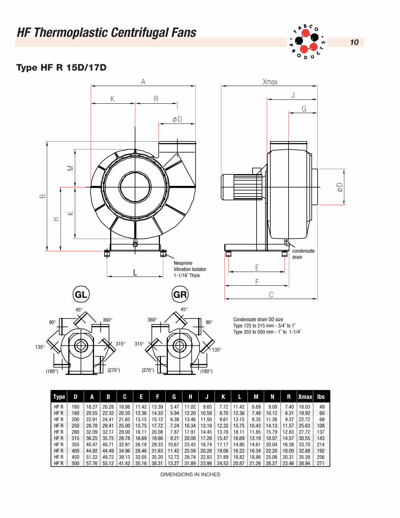
Type HF R 15D/17D
Condensate drain OD sizeType 125 to 315 mm - 3/4˝ to 1˝Type 355 to 500 mm - 1˝ to 1-1/4˝
A Xmax
D
L
K
K
H
B
M
RG
E
F
C
J
D
condensatedrain
NeopreneVibration Isolator1-1/16˝ Thick
360° 360°
315° 315°
(270°) (270°)(180°) (180°)
135° 135°
90° 90°
45° 45°
GL GR
Type D A B C E F G H J K L M N R Xmax lbs
HF RHF RHF RHF RHF RHF RHF RHF RHF RHF R
160180200250280315355400450500
18.2720.5522.9128.7832.0936.2540.4744.9251.2257.76
20.2822.3224.4129.4132.1735.7540.7144.4949.7255.12
18.8620.3521.6525.0028.0028.7832.9134.9639.1341.42
11.4212.3613.1515.7518.1116.6926.1828.4632.0535.16
13.3914.3315.1217.7220.0818.6629.3331.6335.2038.31
5.475.946.387.247.879.21
10.6711.4212.7213.27
11.0212.2013.4616.3417.9120.0823.4325.5928.7431.89
9.6510.5911.5013.1914.4517.2818.7420.2822.8323.98
7.728.709.61
12.3213.7815.4717.1719.0621.8924.53
11.4212.3613.1515.7518.1116.6914.8016.2218.8220.87
6.697.488.35
10.4311.8513.1914.6116.3418.8621.26
9.0910.1211.2614.1315.7918.0720.0422.2025.0828.27
7.408.319.37
11.5712.8314.5716.3818.0020.3123.46
18.0319.9222.7225.6327.7230.5533.7032.8835.3938.94
496068
108137143214192256271
DIMENSIONS IN INCHES
HF Thermoplastic Centrifugal Fans11
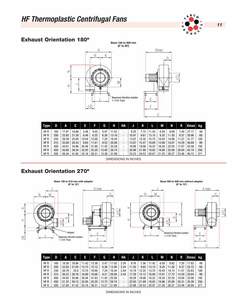
Exhaust Orientation 180º
Neoprene Vibration Isolator1-1/16˝ Thick
Sizes 125 to 500 mm(5˝ to 20˝)
C
F
E
G
XmaxA
R K
L
H J M
N
D
DExhaust Orientation 270º
Neoprene Vibration Isolator1-1/16˝ Thick
Neoprene Vibration Isolator1-1/16˝ Thick
Adapter
Sizes 125 to 315 mm with adapter(5˝ to 12˝)
Sizes 355 to 500 mm without adapter(5˝ to 12˝)
J X maxJ
M G
C
F
E
N
L
HK
R
A
MN
L
HAH
K
RA
D D
D
X max
G
C
F
E
D
Type D A C E F G H HA J K L M N R Xmax kg
HF RHF RHF RHF RHF RHF RHF R
160200250315400450500
17.9123.8328.3935.8944.6150.0856.34
18.8621.3825.0028.4334.9638.5441.65
3.488.46
10.049.65
28.4632.0535.18
9.456.25
12.0011.6131.6035.2038.31
5.476.387.249.52
11.4212.4013.38
11.0213.1616.3420.0825.5828.7431.89
-------
9.2510.9113.0715.6718.9020.9823.23
7.729.61
12.3215.4719.0621.8924.53
11.4313.1515.7516.6916.2218.8220.87
6.508.35
10.4313.9816.0418.8621.25
9.0911.3014.0618.0722.0525.0828.27
7.409.37
11.2714.2917.8720.0423.46
27.1728.8631.7736.6942.5643.1946.73
4968
10899
192256271
DIMENSIONS IN INCHES
Type D A C E F G H HA J K L M N R Xmax kg
HF RHF RHF RHF RHF RHF RHF R
160200230315400450500
18.2622.8328.7836.2544.9251.2257.80
18.8621.65
25.028.7834.9639.1341.42
11.4213.1515.7516.6928.4632.0535.16
13.3915.1218.9018.6631.6335.2038.31
5.476.387.249.21
11.4212.7213.27
11.0213.4616.3420.0825.5928.7431.89
2.242.242.442.44
- - -
9.7611.5013.1917.2820.2822.8323.98
7.569.65
12.3215.1219.0621.8924.53
11.4213.1515.7516.6916.2218.8220.87
6.508.35
10.4312.9116.3418.8621.26
8.8211.2614.1317.7222.2025.0828.27
7.209.37
11.5714.2918.0020.3123.46
17.8322.7225.6329.8432.8835.3938.94
4968
10899
192256271
DIMENSIONS IN INCHES

HF Thermoplastic Centrifugal Fans12
HF R 75-16D
0.1 - 25
30
35
0.16 - 40455055
0.24 - 60
70
0.32 - 80
100
0.48 - 120
140
0.72 - 180
220
1.0 - 260
3450 0.20 2 2800 0.18 2 18.3
1725 0.14 4
1325 0.12 4 8.9
Pt[Pa]
PtInches W.G.
25 30 40 50 60 70 80 100 130 160 200 240 280
V [CFM]
V [cbm/h]
c [m/s]
15 18 24 30 35 40 47 59 75 95 117 140 165
Acoustic level
Free entry-/free exit-acoustic power levelaccording to d 'A'; Lw5A=Lw6A
Free entry-/free exitacoustic pressure
level at 1m distanceLp5A = Lp6A
Measurement areaacoustic pressure at1m distance Lp2A
with connected pipesAveraged octave bands [Hz]
Speed[1/min]
63 125 250 500 1000 2000 4000 8000 dB(A) dB(A)2800 62 66 75 67 63 51 43 35 54 471325 56 58 67 59 55 43 35 27 45 39
1.5 2 3 4 5 6 7 8 9 10 12 14 16
n[1/min]
PM[kW]
Pol-zahl
u[m/s]
HF Thermoplastic Centrifugal Fans13
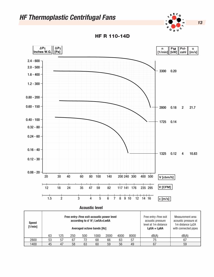
HF R 110-14D
0.08 - 20
0.12 - 30
0.16 - 40
0.24 - 60
0.32 - 80
0.40 - 100
0.60 - 150
0.80 - 200
1.2 - 300
1.6 - 400
2.0 - 500
2.4 - 600
3300 0.20
2800 0.18 2 21.7
1725 0.14
1325 0.12 4 10.83
Pt[Pa]
PtInches W.G.
20 30 40 60 80 100 140 200 240 300 400 500
V [CFM]
V [cbm/h]
c [m/s]
12 18 24 35 47 59 82 117 141 176 235 295
Acoustic level
Free entry-/free exit-acoustic power levelaccording to d 'A'; Lw5A=Lw6A
Free entry-/free exitacoustic pressure
level at 1m distanceLp5A = Lp6A
Measurement areaacoustic pressure at1m distance Lp2A
with connected pipesAveraged octave bands [Hz]
Speed[1/min]
63 125 250 500 1000 2000 4000 8000 dB(A) dB(A)2800 53 57 67 72 68 66 63 57 75 671400 45 47 58 63 60 59 56 49 67 59
1.5 2 3 4 5 6 7 8 9 10 12 14 16
n[1/min]
PM[kW]
Pol-zahl
u[m/s]
HF Thermoplastic Centrifugal Fans14
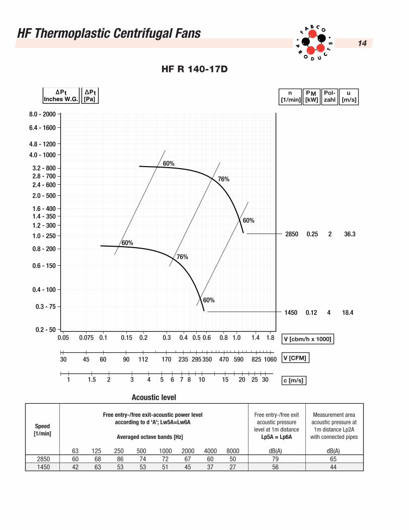
HF R 140-17D
0.2 - 50
0.3 - 75
0.4 - 100
0.6 - 150
0.8 - 200
1.0 - 250
1.2 - 3001.4 - 3501.6 - 400
2.0 - 500
2.4 - 6002.8 - 7003.2 - 800
4.0 - 1000
4.8 - 1200
6.4 - 1600
8.0 - 2000
2850
60%
60%
60%
60%
76%
76%
0.25 2 36.3
1450 0.12 4 18.4
Pt[Pa]
PtInches W.G.
0.05 0.075 0.1 0.15 0.2 0.3 0.4 0.5 0.6 0.8 1.0 1.4 1.8
V [CFM]
V [cbm/h x 1000]
c [m/s]
30 45 60 90 112 170 235 295 350 470 590 825 1060
Acoustic level
Free entry-/free exit-acoustic power levelaccording to d 'A'; Lw5A=Lw6A
Free entry-/free exitacoustic pressure
level at 1m distanceLp5A = Lp6A
Measurement areaacoustic pressure at1m distance Lp2A
with connected pipesAveraged octave bands [Hz]
Speed[1/min]
63 125 250 500 1000 2000 4000 8000 dB(A) dB(A)2850 60 68 86 74 72 67 60 50 79 651450 42 63 53 53 51 45 37 27 56 44
1 1.5 2 3 4 5 6 7 8 10 15 20 3025
n[1/min]
PM[kW]
Pol-zahl
u[m/s]

HF Thermoplastic Centrifugal Fans15
HF R 160-17D/R
0.3 - 75
0.4 - 100
0.8 - 200
1.2 - 300
1.6 - 400
2.0 - 500
2.4 - 6002.8 - 7003.2 - 800
4.0 - 1000
4.8 - 1200
6.4 - 1600
8.0 - 2000
0.2 - 50
0.6 - 150
1.0 - 250
1.4 - 350
3600 1.1 2 52.2
3200 0.75 2 46.4
2850 0.55 2 41.3
2500 0.37 2 36.3
2200 0.25 2 31.9
1800 0.25 4 26.1
1450 0.25 4 21.0
1200 0.25 4 21.0
60%
60%
60%
76%
76%
76%
60%
60%
60%
[Pa]Pt
W.G.Pt
0.1 0.2 0.4 0.6 0.8 1.00.15 0.3 1.4 2.0 2.8 3.6
CFM
V [cbm/h x1000]
c [m/s]
60 90 120 180 240 350 470 825 1177 1650 2120560
Acoustic level according to DIN 45635
Free entry-/free exit-acoustic power levelaccording to d 'A'; Lw5A=Lw6A
Free entry-/free exitacoustic pressure
level at 1m distanceLp5A = Lp6A
Measurement areaacoustic pressure at1m distance Lp2A
with connected pipesAveraged octave bands [Hz]
Speed[1/min]
63 125 250 500 1000 2000 4000 8000 dB(A) dB(A)3600 70 78 97 85 83 79 72 63 90 763200 67 75 94 81 79 75 68 59 86 732850 64 72 90 78 76 71 64 55 83 692500 61 68 87 74 72 67 60 50 79 652200 57 65 83 70 68 63 56 46 75 611800 52 73 63 64 62 56 49 38 66 551450 46 67 57 57 55 49 41 31 60 481200 41 62 51 52 49 43 35 24 55 42
1.5 2 3 4 5 6 7 8 10 15 20 25 30 40
n[1/min]
PM[kW]
Pol-zahl
u[m/s]
HF Thermoplastic Centrifugal Fans16
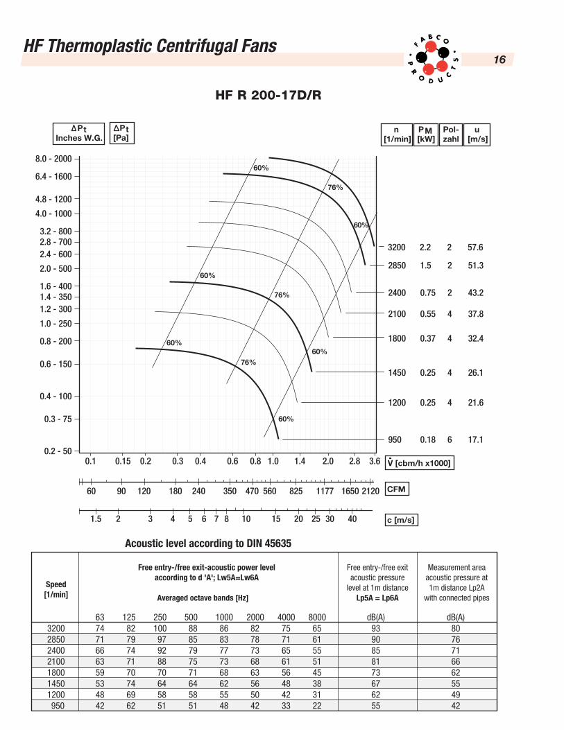
HF R 200-17D/R
0.3 - 75
0.4 - 100
0.8 - 200
1.2 - 300
1.6 - 400
2.0 - 500
2.4 - 6002.8 - 7003.2 - 800
4.0 - 1000
4.8 - 1200
6.4 - 1600
8.0 - 2000
0.2 - 50
0.6 - 150
1.0 - 250
1.4 - 350
0.1 0.2 0.4 0.6 0.8 1.00.15 0.3 1.4 2.0 2.8 3.6
3200 2.2 2 57.6
2850 1.5 2 51.3
2400 0.75 2 43.2
2100 0.55 4 37.8
1800 0.37 4 32.4
1450 0.25 4 26.1
1200 0.25 4 21.6
950 0.18 6 17.1
60%
60%
60%
76%
76%
76%
60%
60%
60%
Inches W.G.Pt n
[1/min]PM[kW]
Pol-zahl
u[m/s]
CFM
V [cbm/h x1000]
c [m/s]
60 90 120 180 240 350 470 825 1177 1650 2120560
Acoustic level according to DIN 45635
Free entry-/free exit-acoustic power levelaccording to d 'A'; Lw5A=Lw6A
Free entry-/free exitacoustic pressure
level at 1m distanceLp5A = Lp6A
Measurement areaacoustic pressure at1m distance Lp2A
with connected pipesAveraged octave bands [Hz]
Speed[1/min]
63 125 250 500 1000 2000 4000 8000 dB(A) dB(A)3200 74 82 100 88 86 82 75 65 93 802850 71 79 97 85 83 78 71 61 90 762400 66 74 92 79 77 73 65 55 85 712100 63 71 88 75 73 68 61 51 81 661800 59 70 70 71 68 63 56 45 73 621450 53 74 64 64 62 56 48 38 67 551200 48 69 58 58 55 50 42 31 62 49950 42 62 51 51 48 42 33 22 55 42
1.5 2 3 4 5 6 7 8 10 15 20 25 30 40
[Pa]Pt

HF Thermoplastic Centrifugal Fans17
HF R 250-17D/R
CFM
c [m/s]
118 177 235 353 470 589 825 1766 2354 3237 41201177
Acoustic level according to DIN 45635
Free entry-/free exit-acoustic power levelaccording to d 'A'; Lw5A=Lw6A
Free entry-/free exitacoustic pressure
level at 1m distanceLp5A = Lp6A
Measurement areaacoustic pressure at1m distance Lp2A
with connected pipesAveraged octave bands [Hz]
Speed[1/min]
1.5 2 3 4 5 6 7 8 10 15 20 25 30 40
Pt[Pa]
PtInches W.G.
V [cbm/h x1000]
0.3 - 75
0.4 - 100
0.8 - 200
1.2 - 300
1.6 - 400
2.0 - 500
2.4 - 6002.8 - 7003.2 - 800
4.0 - 1000
4.8 - 1200
6.4 - 1600
8.0 - 2000
0.2 - 50
0.6 - 150
1.0 - 250
1.4 - 350
0.2 0.4 0.6 0.8 1.00.3 1.4 2.0 3.0 4.0 5.5 7.0
2400 3.0 2 54.4
2100 1.5 4 47.6
1800 1.1 4 40.8
1450 0.55 4 32.9
1200 0.37 4 27.2
950 0.18 6 21.5
700 0.12 8 15.9
63 125 250 500 1000 2000 4000 8000 dB(A) dB(A)2400 74 81 100 87 85 80 73 63 91 782100 70 78 96 83 81 76 68 58 87 741800 66 88 77 78 76 71 63 53 80 691450 61 82 71 71 69 63 61 45 74 621200 55 76 65 66 63 57 55 38 68 56950 49 69 58 58 55 49 49 29 62 49700 56 49 51 51 47 41 41 21 50 39
60%
60%
60%
76%
76%
76%
60%
60%
60%
n[1/min]
PM[kW]
Pol-zahl
u[m/s]
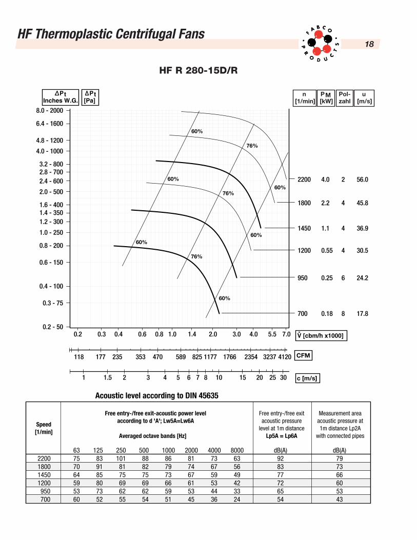
HF Thermoplastic Centrifugal Fans18
HF R 280-15D/R
CFM
c [m/s]
118 177 235 353 470 589 825 1766 2354 3237 41201177
Acoustic level according to DIN 45635
Free entry-/free exit-acoustic power levelaccording to d 'A'; Lw5A=Lw6A
Free entry-/free exitacoustic pressure
level at 1m distanceLp5A = Lp6A
Measurement areaacoustic pressure at1m distance Lp2A
with connected pipesAveraged octave bands [Hz]
Speed[1/min]
Pt[Pa]
PtInches W.G.
V [cbm/h x1000]
0.3 - 75
0.4 - 100
0.8 - 200
1.2 - 300
1.6 - 400
2.0 - 500
2.4 - 6002.8 - 7003.2 - 800
4.0 - 1000
4.8 - 1200
6.4 - 1600
8.0 - 2000
0.2 - 50
0.6 - 150
1.0 - 250
1.4 - 350
0.2 0.4 0.6 0.8 1.00.3 1.4 2.0 3.0 4.0 5.5 7.0
1 1.5 2 3 4 5 6 7 8 10 15 20 25 30
2200 4.0 2 56.0
1800 2.2 4 45.8
1450 1.1 4 36.9
1200 0.55 4 30.5
950 0.25 6 24.2
700 0.18 8 17.8
63 125 250 500 1000 2000 4000 8000 dB(A) dB(A)2200 75 83 101 88 86 81 73 63 92 791800 70 91 81 82 79 74 67 56 83 731450 64 85 75 75 73 67 59 49 77 661200 59 80 69 69 66 61 53 42 72 60950 53 73 62 62 59 53 44 33 65 53700 60 52 55 54 51 45 36 24 54 43
60%
60%
60%
76%
76%
76%
60%
60%
60%
n[1/min]
PM[kW]
Pol-zahl
u[m/s]

HF Thermoplastic Centrifugal Fans19
HF R 315-15D/R
CFM
c [m/s]
118 177 235 353 470 589 825 1766 2354 3237 41201177
Acoustic level according to DIN 45635
Free entry-/free exit-acoustic power levelaccording to d 'A'; Lw5A=Lw6A
Free entry-/free exitacoustic pressure
level at 1m distanceLp5A = Lp6A
Measurement areaacoustic pressure at1m distance Lp2A
with connected pipesAveraged octave bands [Hz]
Speed[1/min]
Pt[Pa]
PtInches W.G.
1 1.5 2 3 4 5 6 7 8 10 11 12 25
V [cbm/h x1000]
0.3 - 75
0.4 - 100
0.8 - 200
1.2 - 300
1.6 - 400
2.0 - 500
2.4 - 6002.8 - 7003.2 - 800
4.0 - 1000
4.8 - 1200
6.4 - 1600
8.0 - 2000
0.2 - 50
0.6 - 150
1.0 - 250
1.4 - 350
0.2 0.4 0.6 0.8 1.00.3 1.4 2.0 3.0 4.0 5.5 7.0
2200 4.0 2 56.0
1800 2.2 4 45.8
1450 1.1 4 36.9
1200 0.55 4 30.5
950 0.25 6 24.2
700 0.18 8 17.8
500 0.12 8 12.7
63 125 250 500 1000 2000 4000 8000 dB(A) dB(A)2200 72 80 93 85 83 79 72 62 85 751800 66 80 78 79 77 72 65 55 77 691450 61 77 72 73 71 65 58 48 71 621200 56 72 67 67 65 59 51 41 66 57950 50 65 60 60 57 51 43 32 59 49700 52 50 53 53 49 43 35 24 50 41500 41 38 40 40 36 29 21 9 37 28
n[1/min]
PM[kW]
Pol-zahl
u[m/s]
60%
60%
60%
81%
81%
81%
60%
60%
60%

HF Thermoplastic Centrifugal Fans20
HF R 355-15D/R
n[1/min]
PM[kW]
Pol-zahl
u[m/s]
CFM
V [cbm/h x1000]
c [m/s]
0.3 - 75
0.4 - 100
0.8 - 200
1.2 - 300
1.6 - 400
2.0 - 500
2.4 - 6002.8 - 7003.0 - 800
4.0 - 1000
4.8 - 1200
6.4 - 1600
8.0 - 2000
0.2 - 50
0.6 - 150
1.0 - 250
1.4 - 350
235 350 470 825 1177 1765 2350 3530 4700 7000
0.60.4 0.8 1.0 1.4 2.0 3.0 4.0 6.0 8.0 12.0
1.51 2 3 4 5 6 7 8 10 15 20 30 40
2000 5.5 4 57.3
1800 4.0 4 51.6
1600 3.0 4 45.8
1450 2.2 4 41.5
1200 1.1 4 34.4
950 0.55 6 27.2
700 0.25 8 20.0
500 0.18 8 14.3
60%
60%
60%
81%
81%
81%
60%
60%
60%
Acoustic level according to DIN 45635
Free entry-/free exit-acoustic power levelaccording to d 'A'; Lw5A=Lw6A
Free entry-/free exitacoustic pressure
level at 1m distanceLp5A = Lp6A
Measurement areaacoustic pressure at1m distance Lp2A
with connected pipesAveraged octave bands [Hz]
Speed[1/min]
63 125 250 500 1000 2000 4000 8000 dB(A) dB(A)2000 73 81 94 86 84 80 72 63 86 761800 70 87 82 83 81 76 69 59 81 731600 67 84 79 80 77 72 65 55 78 691450 65 81 76 77 74 69 62 51 75 661200 60 76 70 71 68 63 55 45 70 60950 53 69 63 64 61 55 47 36 63 53700 56 53 56 56 53 47 39 28 53 45500 45 42 44 43 40 33 42 13 41 32
Pt[Pa]
PtInches W.G.

HF Thermoplastic Centrifugal Fans21
HF R 400-15D/R
Inches W.G.Pt n
[1/min]PM[kW]
Pol-zahl
u[m/s]
CFM
c [m/s]
235 350 470 825 1177 1765 2350 3530 4700 7000
Acoustic level according to DIN 45635
Free entry-/free exit-acoustic power levelaccording to d 'A'; Lw5A=Lw6A
Free entry-/free exitacoustic pressure
level at 1m distanceLp5A = Lp6A
Measurement areaacoustic pressure at1m distance Lp2A
with connected pipesAveraged octave bands [Hz]
Speed[1/min]
Pt[Pa]
V [cbm/h x1000]
0.3 - 75
0.4 - 100
0.8 - 200
1.2 - 300
1.6 - 400
2.0 - 500
2.4 - 6002.8 - 7003.2 - 800
4.0 - 1000
4.8 - 1200
6.4 - 1600
8.0 - 2000
0.2 - 50
0.6 - 150
1.0 - 250
1.4 - 350
0.4 0.6 0.8 1.0 1.4 2.0 3.0 4.0 6.0 8.0 12.0
1.51 2 3 4 5 6 7 8 10 15 20 30
1450 3.0 4 46.1
1200 2.2 4 38.1
950 1.1 6 30.2
700 0.55 8 22.2
600 0.25 8 19.1
500 0.18 8 15.9
63 125 250 500 1000 2000 4000 8000 dB(A) dB(A)1450 68 84 79 80 78 72 65 55 78 691200 63 79 74 74 72 66 58 48 73 64950 57 72 67 67 64 58 50 39 66 56700 59 57 60 60 56 50 42 31 57 48600 52 49 51 51 47 40 32 20 48 39500 48 45 47 47 43 36 28 16 44 35
60%
60%
60%
81%
81%
81%
60%
60%
60%
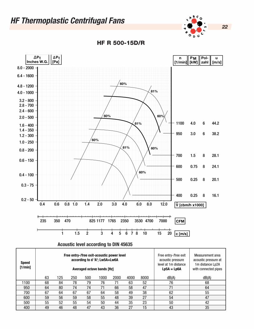
HF Thermoplastic Centrifugal Fans22
HF R 500-15D/R
Inches W.G.Pt n
[1/min]PM[kW]
Pol-zahl
u[m/s]
CFM235 350 470 825 1177 1765 2350 3530 4700 7000
Free entry-/free exit-acoustic power levelaccording to d 'A'; Lw5A=Lw6A
Free entry-/free exitacoustic pressure
level at 1m distanceLp5A = Lp6A
Measurement areaacoustic pressure at1m distance Lp2A
with connected pipesAveraged octave bands [Hz]
Speed[1/min]
Pt[Pa]
V [cbm/h x1000]
c [m/s]
0.3 - 75
0.4 - 100
0.8 - 200
1.2 - 300
1.6 - 400
2.0 - 500
2.4 - 6002.8 - 7003.2 - 800
4.0 - 1000
4.8 - 1200
6.4 - 1600
8.0 - 2000
0.2 - 50
0.6 - 150
1.0 - 250
1.4 - 350
0.4 0.6 0.8 1.0 1.4 2.0 3.0 4.0 6.0 8.0 12.0
1.51 2 3 4 5 6 7 8 10 15 20
1100 4.0 6 44.2
950 3.0 6 38.2
700 1.5 8 28.1
600 0.75 8 24.1
500 0.25 8 20.1
400 0.25 8 16.1
63 125 250 500 1000 2000 4000 8000 dB(A) dB(A)1100 68 84 78 79 76 71 63 52 76 68950 64 80 74 74 71 66 58 47 71 64700 67 64 67 67 64 58 49 38 62 55600 59 56 59 58 55 48 39 27 54 47500 55 52 55 54 50 44 35 23 50 42400 49 46 48 47 43 36 27 15 43 35
60%
60%
60%
81%
81%
81%
60%
60%
60%
Acoustic level according to DIN 45635

HF Thermoplastic Centrifugal Fans23
HF R 560-13D/R
Inches W.G.Pt n
[1/min]PM[kW]
Pol-zahl
u[m/s]
CFM x 10001.7 2.55 3.4 5.1 6.8 8.5 12.7 17.0 25.0 34.0 42.5 51
Free entry-/free exit-acoustic power levelaccording to d 'A'; Lw5A=Lw6A
Free entry-/free exitacoustic pressure
level at 1m distanceLp5A = Lp6A
Measurement areaacoustic pressure at1m distance Lp2A
with connected pipesAveraged octave bands [Hz]
Speed[1/min]
Pt[Pa]
V [cbm/h x1000]
c [m/s]
0.3 - 75
0.4 - 100
0.8 - 200
1.2 - 300
1.6 - 400
2.0 - 500
2.4 - 6002.8 - 7003.2 - 800
4.0 - 1000
4.8 - 1200
6.4 - 1600
8.0 - 2000
0.2 - 50
0.6 - 150
1.0 - 250
1.4 - 350
1.0 1.5 2.0 3.0 4.0 5.0 7.5 10 15 20 25 30 35
321.5 4 65 87 10 15 20 25 30 40
940 4.0 6 35.8
800 2.2 8 30.5
705 1.5 8 26.9
620 1.1 8 23.6
515 0.75 8 19.6
455 0.55 8 17.3
63 125 250 500 1000 2000 4000 8000 dB(A) dB(A)1060 74 80 81 79 73 68 59 45 80 69940 71 77 78 76 71 64 55 42 77 66800 66 72 73 71 66 59 51 36 72 61705 63 68 69 67 62 55 46 32 68 57620 59 64 65 63 57 51 42 28 64 53515 53 59 60 57 51 44 36 17 58 48455 50 55 55 53 47 41 32 17 54 43
1060 5.5 6 40.4
Acoustic level according to DIN 45635
160/1
80 B
elt
Dri
ve24
Velo
city
CFM
(ft3 /
min
)CM
H(m
3 /hr
)19
92 P
a8˝
SP
1370
Pa
5.5˝
SP
1494
Pa
6˝ S
P16
19 P
a6.
5˝ S
P17
43 P
a7˝
SP
872
Pa3.
5˝ S
P99
6 Pa
4˝ S
P11
21 P
a4.
5˝ S
P12
45 P
a5˝
SP
374
Pa1.
5˝ S
P49
8 Pa
2˝ S
P62
3 Pa
2.5˝
SP
747
Pa3˝
SP
124.
5 Pa
1/2˝
SP
187
Pa3/
4˝ S
P24
9 Pa
1˝ S
P31
1 Pa
1.25
˝ SP
RPM
BHP
RPM
BHP
RPM
BHP
RPM
BHP
RPM
BHP
RPM
BHP
RPM
BHP
RPM
BHP
RPM
BHP
RPM
1725
3450
872
Pa3.
5˝ S
P37
4 Pa
1.5˝
SP
498
Pa2˝
SP
623
Pa2.
5˝ S
P74
7 Pa
3˝ S
P12
4.5
Pa1/
2˝ S
P18
7 Pa
3/4˝
SP
249
Pa1˝
SP
311
Pa1.
25˝ S
P
CFM
BHP
CFM
BHP
CFM
BHP
CFM
BHP
CFM
BHP
CFM
BHP
CFM
BHP
CFM
BHP
CFM
BHP
RPM
BHP
RPM
BHP
RPM
BHP
RPM
BHP
RPM
BHP
RPM
BHP
RPM
BHP
RPM
BHP
1992
Pa
8˝ S
P13
70 P
a5.
5˝ S
P14
94 P
a6˝
SP
1619
Pa
6.5˝
SP
1743
Pa
7˝ S
P3.
5˝ S
P99
6 Pa
4˝ S
P11
21 P
a4.
5˝ S
P12
45 P
a5˝
SP
3˝ S
P
CFM
BHP
CFM
BHP
CFM
BHP
CFM
BHP
CFM
BHP
CFM
BHP
CFM
BHP
CFM
BHP
100
170
463
990
0.02
1201
0.01
1381
0.02
1540
0.03
1687
0.03
1944
0.05
2172
0.06
200
340
926
1069
0.02
1624
0.02
1434
0.03
1586
0.04
1727
0.05
1977
0.07
2200
0.09
2401
0.12
2589
0.14
2762
0.16
2927
0.19
3082
0.21
3231
0.23
3372
0.26
3508
0.28
194
0.05
1123
0.56
1054
0.58
977
0.59
918
0.59
806
0.57
701
0.54
573
0.5
398
0.42
300
510
2084
1196
0.02
1371
0.04
1528
0.05
1670
0.06
1803
0.07
2041
0.09
2256
0.12
2452
0.15
2634
0.18
2804
0.21
2966
0.24
3118
0.27
3264
0.30
3403
0.34
3537
0.37
3666
0.41
3192
0.15
593
0.06
526
0.07
447
0.07
350
0.06
1364
0.23
1336
0.30
1309
0.37
1280
0.42
1250
0.46
1189
0.52
400
680
1852
1356
0.04
1512
0.05
1674
0.06
1785
0.10
1910
0.09
2134
0.12
2339
0.16
2527
0.19
2641
0.21
2868
0.39
3025
0.30
3173
0.34
3316
0.37
3453
0.41
3585
0.45
3711
0.49
3953
0.58
450
765
2083
1446
0.04
1592
0.06
1727
0.07
1853
0.09
1973
0.11
2190
0.14
2390
0.18
2573
0.21
2746
0.25
2870
0.39
3063
0.33
3209
0.37
3350
0.41
3484
0.45
3615
0.49
3740
0.54
3980
0.63
500
850
2315
1540
0.05
1678
0.07
1806
0.08
1926
0.10
2041
0.12
2251
0.16
2446
0.19
2625
0.23
2794
0.27
2915
0.30
3105
0.36
3249
0.40
3388
0.44
3520
0.48
3649
0.53
3773
0.58
4010
0.67
550
934
2546
1636
0.06
1766
0.08
1888
0.10
2003
0.12
2114
0.13
2317
0.17
2505
0.21
2680
0.26
2846
0.30
2964
0.33
3150
0.39
3292
0.43
3429
0.48
3558
0.53
3687
0.57
3810
0.62
4044
0.72
600
1019
2778
1737
0.07
1860
0.09
1976
0.11
2085
0.13
2192
0.15
2388
0.19
2571
0.24
2741
0.28
2902
0.32
3019
0.36
3201
0.42
3340
0.47
3475
0.52
3602
0.57
3730
0.62
3850
0.67
4082
0.78
650
1104
3009
1840
0.08
1956
0.10
2067
0.12
2172
0.15
2274
0.17
2463
0.25
2641
0.26
2806
0.31
2963
0.35
3077
0.39
3256
0.45
3392
0.50
3525
0.55
3652
0.61
3776
0.66
3895
0.71
4123
0.83
700
1189
3241
2056
0.11
2161
0.14
2261
0.16
2359
0.19
2541
0.23
2713
0.28
2874
0.33
3028
0.38
3174
0.44
3314
0.49
3448
0.54
3579
0.60
3703
0.65
3825
0.71
3942
0.76
4168
0.88
750
1276
3473
2257
0.15
2354
0.18
2448
0.21
2624
0.21
2790
0.31
2947
0.36
3097
0.42
3205
0.46
3376
0.53
3508
0.58
3636
0.64
3758
0.70
3878
0.75
3994
0.81
4216
0.93
800
1359
3704
2357
0.17
2449
0.20
2540
0.23
2709
0.28
2871
0.34
3023
0.39
3169
0.45
3275
0.49
3442
0.56
3571
0.62
3696
0.68
3817
0.74
3935
0.80
4048
0.87
900
1529
4167
2561
0.20
2646
0.24
2730
0.27
2888
0.34
3039
0.40
3183
0.46
3321
0.52
3422
0.59
3582
0.65
3706
0.71
3826
0.78
3943
0.84
4056
0.91
4166
0.98
1000
1699
4630
2772
0.24
2850
0.28
2928
0.32
3076
0.39
3218
0.47
3353
0.53
3485
0.60
3611
0.67
3734
0.74
3852
0.81
3968
0.88
4080
0.95
4189
1.03
4296
1.10
1100
1869
5093
3061
0.33
3138
0.38
3271
0.46
3405
0.54
3533
0.62
3658
0.69
3778
0.77
3895
0.84
4008
0.92
4149
1.00
4227
1.07
1200
2039
5556
3275
0.38
3343
0.43
3472
0.53
3599
0.62
3720
0.70
3833
0.79
3952
0.87
4064
0.95
4173
1.04
4279
1.07
1300
2209
6019
3680
0.60
3800
0.70
3913
0.80
4026
0.89
4135
1.18
4242
1.07
1400
2379
6482
4003
0.79
4112
0.89
4219
1.00
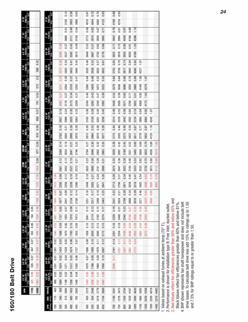
1.Va
lves
bas
ed o
n ex
haus
t fum
es a
t am
bien
t tem
p (7
0°F.
).2.
Perfo
rman
ce is
sho
wn
for i
nsta
llatio
n ty
pe B
:Fre
e in
let,
duct
ed o
utle
t.3.
Red
Valu
es re
flect
fan
effic
ienc
ies
grea
ter t
han
50%
and
bel
ow 6
0%an
dBl
ack
Valu
es re
flect
fan
effic
ienc
ies
grea
ter t
han
60%
and
bel
ow 8
1%.
4.BH
P sh
own
repr
esen
ts fa
n sh
aft h
orse
pow
er a
nd d
oes
not i
nclu
de b
elt
driv
e lo
sses
.To
calc
ulat
e be
lt dr
ive
loss
add
15%
to ra
tings
up
to 1
.50
and
7.5%
for B
HP ra
tings
equ
al to
or g
reat
er th
an 1
.50.
25
200/2
25 B
elt
Dri
ve
Velo
city
FPM
CFM
(ft3 /
min
)CMH(
m3 /
hr)
1992
Pa
8˝ S
P13
70 P
a5.
5˝ S
P14
94 P
a6˝
SP
1619
Pa
6.5˝
SP
1743
Pa
7˝ S
P87
2 Pa
3.5˝
SP
996
Pa4˝
SP
1121
Pa
4.5˝
SP
1245
Pa
5˝ S
P37
4 Pa
1.5˝
SP
498
Pa2˝
SP
623
Pa2.
5˝ S
P74
7 Pa
3˝ S
P12
4.5
Pa1/
2˝ S
P18
7 Pa
3/4˝
SP
249
Pa1˝
SP
311
Pa1.
25˝ S
P
RPM
BHP
RPM
BHP
RPM
BHP
RPM
BHP
RPM
BHP
RPM
BHP
RPM
BHP
RPM
BHP
RPM
BHP
RPM
1140
1725
872
Pa3.
5˝ S
P37
4 Pa
1.5˝
SP
498
Pa2˝
SP
623
Pa2.
5˝ S
P74
7 Pa
3˝ S
P12
4.5
Pa1/
2˝ S
P18
7 Pa
3/4˝
SP
249
Pa1˝
SP
311
Pa1.
25˝ S
P
CFM
BHP
CFM
BHP
CFM
BHP
CFM
BHP
CFM
BHP
CFM
BHP
CFM
BHP
CFM
BHP
CFM
BHP
RPM
BHP
RPM
BHP
RPM
BHP
RPM
BHP
RPM
BHP
RPM
BHP
RPM
BHP
RPM
BHP
1992
Pa
8˝ S
P13
70 P
a5.
5˝ S
P14
94 P
a6˝
SP
1619
Pa
6.5˝
SP
1743
Pa
7˝ S
P3.
5˝ S
P99
6 Pa
4˝ S
P11
21 P
a4.
5˝ S
P12
45 P
a5˝
SP
3˝ S
P
CFM
BHP
CFM
BHP
CFM
BHP
CFM
BHP
CFM
BHP
CFM
BHP
CFM
BHP
CFM
BHP
200
340
592
811
0.02
978
0.03
1121
0.04
1248
0.05
1365
0.06
1570
0.08
1753
0.11
300
510
888
856
0.02
1014
0.04
1151
0.05
1274
0.06
1388
0.08
1589
0.11
1771
0.14
1932
0.17
2083
0.21
2223
0.24
2356
0.28
2481
400
680
1183
917
0.03
1065
0.05
1196
0.06
1314
0.08
1424
0.10
1620
0.13
1796
0.19
1955
0.21
2104
0.25
2242
0.30
2373
0.34
2497
0.38
2615
0.43
2728
0.47
2837
0.52
2941
0.57
3140
0.66
450
765
1331
953
0.04
1096
0.05
1223
0.07
1338
0.09
1446
0.11
1639
0.15
1812
0.19
1970
0.23
2118
0.28
2255
0.32
2385
0.37
2507
0.42
2625
0.46
2737
0.51
2846
0.56
2950
0.61
3148
0.72
500
850
1479
992
0.04
1130
0.06
1253
0.08
1365
0.10
1471
0.12
1660
0.16
1831
0.20
1987
0.25
2133
0.30
2269
0.35
2398
0.40
2520
0.45
2637
0.50
2748
0.55
2856
0.61
2960
0.66
3157
0.77
550
934
1627
1033
0.05
1165
0.07
1285
0.09
1394
0.11
1498
0.13
1683
0.17
1852
0.22
2006
0.28
2151
0.32
2285
0.37
2413
0.42
2534
0.48
2650
0.53
2761
0.59
2868
0.65
2971
0.70
3167
0.77
600
1019
1775
1076
0.05
1204
0.07
1319
0.10
1426
0.12
1527
0.14
1709
0.19
1875
0.24
2027
0.29
2170
0.34
2303
0.39
2430
0.45
2550
0.51
2665
0.58
2775
0.62
2882
0.69
2984
0.75
3179
0.87
650
1104
1923
1122
0.06
1244
0.08
1356
0.10
1460
0.13
1558
0.15
1737
0.20
1900
0.25
2050
0.31
2191
0.36
2323
0.42
2448
0.48
2567
0.54
2681
0.60
2791
0.66
2896
0.72
2998
0.79
3192
0.92
700
1189
2071
1169
0.07
1287
0.09
1395
0.11
1496
0.14
1592
0.16
1737
0.22
1927
0.27
2075
0.33
2214
0.39
2344
0.44
2468
0.51
2586
0.57
2699
0.63
2808
0.70
2913
0.76
3013
0.83
3206
0.97
750
1274
2219
1218
0.07
1331
0.10
1436
0.12
1534
0.15
1628
0.18
1798
0.23
1956
0.29
2110
10.
3522
380.
4123
670.
4724
900.
5426
060.
6027
190.
6728
260.
7429
300.
8130
300.
8832
221.
02
800
1359
2367
1268
0.08
1377
0.11
1478
0.14
1574
0.16
1665
0.19
1832
0.25
1987
0.31
2130
0.37
2265
0.44
2392
0.50
2513
0.57
2628
0.63
2740
0.70
2846
0.77
2950
0.81
3049
0.92
3239
1.07
900
1529
2663
1372
0.10
1473
0.13
1568
0.16
1657
0.19
1744
0.22
1904
0.29
2053
0.35
2191
0.42
2322
0.49
2416
0.54
2564
0.63
2677
0.70
2786
0.78
2890
0.85
2992
0.93
3089
1.01
3277
1.17
1000
1699
2959
1479
0.12
1573
0.15
1662
0.19
1747
0.22
1829
0.26
1981
0.33
2124
0.40
2258
0.47
2385
0.54
2476
0.60
2621
0.70
2731
0.77
2837
0.85
2940
0.93
3039
1.02
3135
1.10
3319
1.27
1100
1869
3254
1677
0.18
1761
0.22
1841
0.26
1919
0.30
2064
0.37
2201
0.45
2330
0.53
2453
0.60
2570
0.69
2682
0.77
2789
0.85
2894
0.94
2994
1.02
3090
1.11
3185
1.20
1200
2039
3550
1784
0.20
1863
0.25
1938
0.29
2013
0.34
2151
0.42
2283
0.50
2407
0.59
2526
0.67
2639
0.77
2748
0.84
2853
0.93
2955
1.02
3053
1.11
3148
1.21
3240
1.30
1300
2209
3846
1968
0.28
2040
0.33
2110
0.38
2243
0.47
2369
0.56
2488
0.65
2603
0.74
2687
0.81
2819
0.93
2921
1.02
3020
1.11
3116
1.21
3209
1.31
3300
1.41
1400
2379
4144
2076
0.32
2141
0.37
2211
0.73
2337
0.53
2459
0.62
2574
0.71
2685
0.82
2791
0.91
2894
1.01
2993
1.11
3090
1.21
3183
1.31
3275
1.42
1500
2549
4440
2250
0.42
2314
0.47
2435
0.58
2551
0.69
2662
0.79
2770
0.90
2848
0.97
2973
1.11
3069
1.21
3163
1.32
3254
1.42
1600
2718
4736
2358
0.46
2419
0.53
2535
0.64
2647
0.76
2753
0.87
2857
0.98
2957
1.09
3054
1.20
3148
1.31
3240
1.43
1700
2888
5032
2526
0.59
2637
0.71
2745
0.83
2848
0.95
2948
1.07
3022
1.16
3139
1.31
3230
1.42
1800
3058
5328
2636
0.63
2742
0.78
2846
0.91
2945
1.04
3042
1.17
3136
1.29
3227
1.41
1900
3228
5624
2849
0.84
2949
0.99
3044
1.13
3138
1.26
3207
1.36
2000
3398
5920
2957
0.92
3053
1.07
3146
1.22
3237
1.36
670
0.06
516
0.06
271
0.05
1242
0.16
1145
0.19
1062
0.21
974
0.21
877
0.22
630
0.2
1.Va
lves
bas
ed o
n ex
haus
t fum
es a
t am
bien
t tem
p (7
0°F.
).2.
Perfo
rman
ce is
sho
wn
for i
nsta
llatio
n ty
pe B
:Fre
e in
let,
duct
ed o
utle
t.3.
Red
Valu
es re
flect
fan
effic
ienc
ies
grea
ter t
han
50%
and
bel
ow 6
0%an
dBl
ack
Valu
es re
flect
fan
effic
ienc
ies
grea
ter t
han
60%
and
bel
ow 8
1%.
4.BH
P sh
own
repr
esen
ts fa
n sh
aft h
orse
pow
er a
nd d
oes
not i
nclu
de b
elt
driv
e lo
sses
.To
calc
ulat
e be
lt dr
ive
loss
add
15%
to ra
tings
up
to 1
.50
and
7.5%
for B
HP ra
tings
equ
al to
or g
reat
er th
an 1
.50.
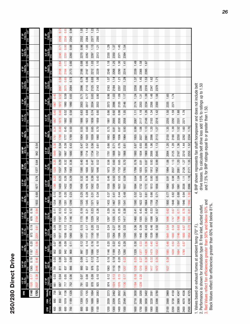
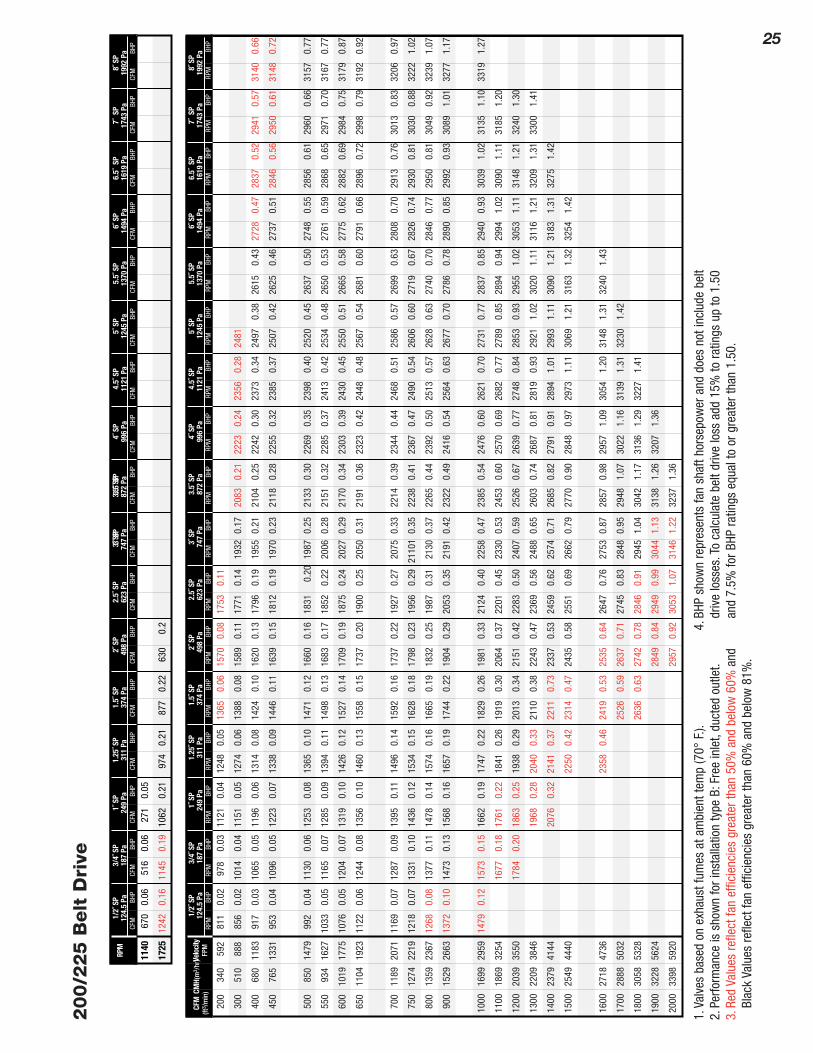
26250/2
80 D
irect
Dri
ve
Velo
city
(FPM
)CF
M(ft
3 /m
in)
CMH
(m3 /
hr)
1370
Pa
5.5˝
SP
1494
Pa
6˝ S
P16
19 P
a6.
5˝ S
P17
43 P
a7˝
SP
872
Pa3.
5˝ S
P99
6 Pa
4˝ S
P11
21 P
a4.
5˝ S
P12
45 P
a5˝
SP
374
Pa1.
5˝ S
P49
8 Pa
2˝ S
P62
3 Pa
2.5˝
SP
747
Pa3˝
SP
124.
5 Pa
1/2˝
SP
187
Pa3/
4˝ S
P24
9 Pa
1˝ S
P31
1 Pa
1.25
˝ SP
RPM
BHP
RPM
BHP
RPM
BHP
RPM
BHP
RPM
BHP
RPM
BHP
RPM
BHP
RPM
BHP
RPM
BHP
RPM
872
Pa3.
5˝ S
P37
4 Pa
1.5˝
SP
498
Pa2˝
SP
623
Pa2.
5˝ S
P74
7 Pa
3˝ S
P12
5 Pa
1/2˝
SP
187
Pa3/
4˝ S
P24
9 Pa
1˝ S
P31
1 Pa
1.25
˝ SP
CFM
BHP
CFM
BHP
CFM
BHP
CFM
BHP
CFM
BHP
CFM
BHP
CFM
BHP
CFM
BHP
CFM
BHP
RPM
BHP
RPM
BHP
RPM
BHP
RPM
BHP
RPM
BHP
RPM
BHP
RPM
BHP
1370
Pa
5.5˝
SP
1494
Pa
6˝ S
P16
19 P
a6.
5˝ S
P17
43 P
a7˝
SP
3.5˝
SP
996
Pa4˝
SP
1121
Pa
4.5˝
SP
1245
Pa
5˝ S
P3˝
SP
CFM
BHP
CFM
BHP
CFM
BHP
CFM
BHP
CFM
BHP
CFM
BHP
CFM
BHP
400
680
758
661
0.03
791
0.05
902
0.07
1001
0.09
1093
0.11
1254
0.15
1399
0.20
1529
0.25
1649
0.30
1761
0.34
1867
0.40
1967
0.45
500
850
947
687
0.04
811
0.06
920
0.06
1017
0.10
1107
0.13
1266
0.18
1409
0.23
1537
0.29
1657
0.34
1768
0.40
1873
0.46
1972
0.52
2067
0.58
2158
0.64
2245
0.71
2328
0.77
600
1019
1136
717
0.05
837
0.07
942
0.09
1036
0.12
1124
0.15
1281
0.20
1422
0.26
1549
0.32
1667
0.39
1777
0.45
1882
0.52
1980
0.59
2075
0.65
2164
0.72
2251
0.80
2334
0.87
700
1189
1326
752
0.06
866
0.08
968
0.11
1060
0.14
1146
0.17
1299
0.23
1438
0.29
1563
0.36
1680
0.43
1789
0.50
1893
0.58
1990
0.65
2084
0.73
2173
0.80
2260
0.88
2342
0.96
800
1359
1515
791
0.07
900
0.09
997
0.12
1087
0.15
1170
0.19
1320
0.25
1456
0.32
1580
0.40
1696
0.47
1804
0.55
1906
0.63
2003
0.71
2096
0.79
2186
0.88
2270
0.96
2352
1.05
900
1529
1705
833
0.08
937
0.11
1030
0.14
1117
0.17
1198
0.21
1345
0.28
1478
0.36
1600
0.44
1714
0.52
1820
0.60
1922
0.69
2017
0.77
2110
0.86
2197
0.95
2282
1.05
2364
1.14
1000
1699
1894
878
0.09
976
0.12
1066
0.16
1150
0.20
1229
0.23
1371
0.31
1502
0.39
1622
0.47
1734
0.56
1839
0.65
1939
0.74
2034
0.83
2125
0.93
2212
1.03
2297
1.13
2377
1.22
1100
1869
2083
925
0.10
1019
0.14
1105
0.18
1185
0.22
1262
0.26
1401
0.34
1529
0.43
1646
0.52
1757
0.61
1860
0.70
1959
0.80
2053
0.90
2143
1.00
2229
1.10
2313
1.21
2393
1.31
1200
2039
2273
974
0.12
1063
0.16
1146
0.20
1223
0.24
1297
0.29
1433
0.37
1558
0.46
1673
0.56
1781
0.66
1883
0.75
1981
0.86
2073
0.96
2163
1.07
2248
1.18
2330
1.29
1300
2209
2462
1024
0.13
1110
0.18
1189
0.22
1264
0.27
1335
0.31
1467
0.41
1589
0.50
1702
0.60
1808
0.71
1909
0.81
2005
0.92
2096
1.03
2184
1.14
2268
1.25
2350
1.37
1400
2379
2652
1076
0.15
1158
0.20
1234
0.25
1306
0.30
1375
0.35
1503
0.44
1622
0.55
1732
0.65
1837
0.76
1936
0.87
2030
0.98
2120
1.09
2207
1.21
2290
1.30
2371
1.45
1500
2549
2841
1130
0.17
1207
0.22
1280
0.28
1350
0.33
1417
0.38
1541
0.48
1657
0.59
1765
0.70
1868
0.81
1964
0.93
2058
1.05
2146
1.17
2232
1.29
2314
1.41
2394
1.54
1600
2718
3030
1184
0.18
1258
0.25
1328
0.30
1395
0.36
1460
0.41
1580
0.52
1694
0.64
1799
0.76
1900
0.87
1955
0.99
2087
1.11
2174
1.24
2258
1.37
2339
1.49
1700
2888
3200
1239
0.20
1310
0.27
1377
0.33
1442
0.39
1505
0.45
1622
0.57
1732
0.69
1835
0.81
1934
0.93
2027
1.06
2117
1.18
2203
1.31
2286
1.45
2366
1.58
1800
3058
3402
1363
0.30
1428
0.36
1490
0.43
1551
0.49
1664
0.61
1772
0.74
1873
0.87
1969
0.99
2061
1.13
2149
1.26
2234
1.39
2316
1.53
2395
1.67
1900
3228
3591
1417
0.32
1479
0.40
1539
0.46
1598
0.53
1708
0.66
1813
0.80
1912
0.93
2006
1.06
2096
1.20
2183
1.34
2266
1.48
2347
1.62
2000
3398
3780
1472
0.35
1532
0.43
1590
0.50
1647
0.57
1754
0.71
1856
0.85
1952
0.99
2045
1.13
2113
1.27
2218
1.42
2300
1.56
2379
1.71
2100
3568
3969
1527
0.38
1585
0.46
1641
0.54
1696
0.62
1800
0.77
1900
0.91
1994
1.06
2084
1.20
2150
1.35
2255
1.50
2335
1.65
2200
3738
4158
1639
0.50
1693
0.58
1747
0.67
1848
0.82
1945
0.98
2037
1.13
2125
1.28
2190
1.39
2292
1.59
2371
1.74
2300
3908
4347
1694
0.54
1746
0.63
1798
0.71
1897
0.88
1991
1.04
2081
1.20
2167
1.36
2250
1.52
2331
1.68
2400
4078
4536
1749
0.57
1800
0.67
1850
0.76
1946
0.94
2038
1.11
2126
1.27
2210
1.44
2292
1.60
2371
1.78
2500
4248
4725
1854
0.72
1903
0.81
1996
1.00
2086
1.18
2171
1.35
2255
1.52
2334
1.70
1140
1725
1520
0.17
1365
0.19
1187
0.20
2537
0.38
2448
0.48
2354
0.56
2251973
0.61
0.19
2154676
0.64
0.16
1933
0.68
1677
0.78
1377
0.64
942
0.54
1.Va
lves
bas
ed o
n ex
haus
t fum
es a
t am
bien
t tem
p (7
0°F.
).2.
Perfo
rman
ce is
sho
wn
for i
nsta
llatio
n ty
pe B
:Fre
e in
let,
duct
ed o
utle
t.3.
Red
Valu
es re
flect
fan
effic
ienc
ies
grea
ter t
han
50%
and
bel
ow 6
0%an
dBl
ack
Valu
es re
flect
fan
effic
ienc
ies
grea
ter t
han
60%
and
bel
ow 8
1%.
4.BH
P sh
own
repr
esen
ts fa
n sh
aft h
orse
pow
er a
nd d
oes
not i
nclu
de b
elt
driv
e lo
sses
.To
calc
ulat
e be
lt dr
ive
loss
add
15%
to ra
tings
up
to 1
.50
and
7.5%
for B
HP ra
tings
equ
al to
or g
reat
er th
an 1
.50.

27
315/3
15 D
irect
Dri
ve
Velo
city
(FPM
)CF
M(ft
3 /m
in)
CMH
(m3 /
hr)
1370
Pa
5.5˝
SP
1494
Pa
6˝ S
P16
19 P
a6.
5˝ S
P17
43 P
a7˝
SP
872
Pa3.
5˝ S
P99
6 Pa
4˝ S
P11
21 P
a4.
5˝ S
P12
45 P
a5˝
SP
374
Pa1.
5˝ S
P49
8 Pa
2˝ S
P62
3 Pa
2.5˝
SP
747
Pa3˝
SP
124.
5 Pa
1/2˝
SP
187
Pa3/
4˝ S
P24
9 Pa
1˝ S
P31
1 Pa
1.25
˝ SP
RPM
BHP
RPM
BHP
RPM
BHP
RPM
BHP
RPM
BHP
RPM
BHP
RPM
BHP
RPM
BHP
RPM
BHP
RPM
872
Pa3.
5˝ S
P37
4 Pa
1.5˝
SP
498
Pa2˝
SP
623
Pa2.
5˝ S
P74
7 Pa
3˝ S
P12
5 Pa
1/2˝
SP
187
Pa3/
4˝ S
P24
9 Pa
1˝ S
P31
1 Pa
1.25
˝ SP
CFM
BHP
CFM
BHP
CFM
BHP
CFM
BHP
CFM
BHP
CFM
BHP
CFM
BHP
CFM
BHP
CFM
BHP
RPM
BHP
RPM
BHP
RPM
BHP
RPM
BHP
RPM
BHP
RPM
BHP
RPM
BHP
3.5˝
SP
996
Pa4˝
SP
1121
Pa
4.5˝
SP
3˝ S
P
CFM
BHP
CFM
BHP
600
1019
715
602
0.04
714
0.07
811
0.09
899
0.12
980
0.15
1125
0.28
1254
0.28
1372
0.36
1481
0.43
1582
0.51
1678
0.59
1768
0.68
1855
0.77
1937
0.85
800
1359
954
648
0.06
750
0.09
841
0.12
924
0.15
1002
0.18
1142
0.26
1268
0.33
1382
0.41
1489
0.50
1565
0.57
1682
0.68
1771
0.78
1857
0.88
1938
0.98
2017
1.08
1000
1699
1192
704
0.08
798
0.11
883
0.15
961
0.18
1035
0.22
1168
0.30
1289
0.39
1400
0.48
1505
0.57
1579
0.64
1694
0.77
1782
0.88
1866
0.99
1946
1.10
2024
1.21
2098
1.33
1200
2039
1430
769
0.10
854
0.14
933
0.18
1006
0.22
1076
0.26
1203
0.35
1319
0.44
1427
0.54
1528
0.64
1622
0.75
1713
0.86
1798
0.98
1881
1.09
1960
1.21
2026
1.34
1300
2209
1549
803
0.12
885
0.16
961
0.20
1034
0.24
1099
0.29
1223
0.38
1337
0.47
1442
0.58
1542
0.68
1635
0.79
1724
0.91
1809
1.03
1891
1.15
1969
1.27
2044
1.40
1400
2379
1669
839
0.14
917
0.18
990
0.22
1059
0.27
1124
0.31
1245
0.41
1357
0.54
1460
0.60
1558
0.73
1650
0.84
1738
0.96
1821
1.04
1902
1.21
1979
1.34
2054
1.47
1500
2549
1788
877
0.15
951
0.20
1021
0.24
1087
0.29
1151
0.34
1268
0.44
1378
0.54
1479
0.65
1575
0.77
1665
0.89
1752
1.01
1835
1.14
1914
1.27
1991
1.40
2065
1.54
1600
2718
1907
915
0.17
986
0.22
1053
0.27
1117
0.37
1179
0.37
1293
0.47
1400
0.58
1499
0.70
1594
0.81
1683
0.94
1768
1.06
1850
1.19
1928
1.33
2004
1.46
2077
1.60
1700
2888
2026
953
0.19
1022
0.24
1087
0.29
1149
0.35
1207
0.42
1320
0.51
1424
0.62
1521
0.74
1614
0.86
1701
0.99
1786
1.12
1866
1.25
1944
1.39
2018
1.53
2091
1.68
1800
3058
2145
993
0.21
1059
0.27
1122
0.33
1181
0.38
1239
0.44
1347
0.55
1449
0.67
1544
0.79
1635
0.92
1721
1.04
1804
1.18
1883
1.32
1960
1.46
2034
1.60
1900
3228
2265
1034
0.23
1097
0.30
1157
0.36
1215
0.41
1271
0.47
1376
0.59
1496
0.71
1569
0.84
1658
0.97
1743
1.10
1824
1.24
1902
1.38
1978
1.53
2050
1.68
2000
3398
2384
1074
0.26
1135
0.32
1193
0.39
1249
0.45
1304
0.52
1406
0.63
1503
0.76
1595
0.89
1682
1.03
1765
1.13
1854
1.31
1922
1.45
1997
1.60
2068
1.75
2100
3568
2500
1116
0.28
1174
0.35
1231
0.42
1285
0.49
1338
0.55
1437
0.68
1532
0.81
1621
0.95
1707
1.09
1789
1.23
1868
1.37
1943
1.52
2017
1.68
2087
1.83
2200
3738
2622
1158
0.30
1241
0.39
1269
0.46
1321
0.53
1372
0.60
1469
0.73
1562
0.87
1649
1.00
1733
1.15
1813
1.30
1891
1.45
1965
1.60
2038
1.76
2300
3908
2737
1200
0.33
1255
0.42
1307
0.50
1358
0.57
1409
0.64
1502
0.78
1593
0.92
1678
1.07
1760
1.22
1839
1.37
1915
1.52
1988
1.68
2060
1.84
2400
4078
2861
1295
0.45
1346
0.53
1395
0.61
1444
0.69
1536
0.84
1624
0.98
1708
1.13
1788
1.29
1865
1.44
1940
1.60
2012
1.76
2083
1.93
2500
4248
2975
1386
0.58
1434
0.66
1481
0.74
1570
0.89
1656
1.05
1738
1.20
1817
1.36
1893
1.52
1967
1.68
2037
1.85
2600
4417
3099
1472
0.71
1518
0.80
1605
0.95
1689
1.11
1769
1.27
1847
1.43
1903
1.56
1994
1.77
2036
1.93
2800
4587
3337
1511
0.76
1556
0.85
1641
1.01
1723
1.18
1801
1.35
1877
1.51
1950
1.68
2024
1.85
2090
2.03
3000
5097
3570
1673
1.02
1752
1.22
1828
1.40
1902
1.59
1973
1.77
2042
1.96
3200
5437
3808
1753
1.15
1828
1.36
1901
1.57
1972
1.76
2041
1.96
860
1140
1725
1457
0.15
1221
0.15
895
0.14
2159
0.29
2012
0.33
1852
0.34
1673
0.34
1460
0.33
789
0.25
3131
1.10
2928
1.17
2707
1.19
2457
1.17
2166
1.13
1907
1.07
1.Va
lves
bas
ed o
n ex
haus
t fum
es a
t am
bien
t tem
p (7
0°F.
).2.
Perfo
rman
ce is
sho
wn
for i
nsta
llatio
n ty
pe B
:Fre
e in
let,
duct
ed o
utle
t.3.
Red
Valu
es re
flect
fan
effic
ienc
ies
grea
ter t
han
50%
and
bel
ow 6
0%an
dBl
ack
Valu
es re
flect
fan
effic
ienc
ies
grea
ter t
han
60%
and
bel
ow 8
1%.
4.BH
P sh
own
repr
esen
ts fa
n sh
aft h
orse
pow
er a
nd d
oes
not i
nclu
de b
elt
driv
e lo
sses
.To
calc
ulat
e be
lt dr
ive
loss
add
15%
to ra
tings
up
to 1
.50
and
7.5%
for B
HP ra
tings
equ
al to
or g
reat
er th
an 1
.50.

28400/4
00 D
irect
Dri
ve
Velo
city
(FPM
)CF
M(ft
3 /m
in)
CMH
(m3 /
hr)
872
Pa3.
5˝ S
P99
6 Pa
4˝ S
P11
21 P
a4.
5˝ S
P12
45 P
a5˝
SP
374
Pa1.
5˝ S
P49
8 Pa
2˝ S
P62
3 Pa
2.5˝
SP
747
Pa3˝
SP
124.
5 Pa
1/2˝
SP
187
Pa3/
4˝ S
P24
9 Pa
1˝ S
P31
1 Pa
1.25
˝ SP
RPM
BHP
RPM
BHP
RPM
BHP
RPM
BHP
RPM
BHP
RPM
BHP
RPM
BHP
RPM
BHP
RPM
BHP
RPM
872
Pa3.
5˝ S
P37
4 Pa
1.5˝
SP
498
Pa2˝
SP
623
Pa2.
5˝ S
P74
7 Pa
3˝ S
P12
5 Pa
1/2˝
SP
187
Pa3/
4˝ S
P24
9 Pa
1˝ S
P31
1 Pa
1.25
˝ SP
CFM
BHP
CFM
BHP
CFM
BHP
CFM
BHP
CFM
BHP
CFM
BHP
CFM
BHP
CFM
BHP
CFM
BHP
RPM
BHP
RPM
BHP
RPM
BHP
3.5˝
SP
996
Pa4˝
SP
1121
Pa
4.5˝
SP
3˝ S
P
CFM
BHP
CFM
BHP
800
1359
591
470
0.06
562
0.09
642
0.13
714
0.17
780
0.22
897
0.31
1002
0.41
1097
0.52
1185
0.63
1247
0.71
1200
2039
887
512
0.09
595
0.13
669
0.18
736
0.23
799
0.28
911
0.39
1013
0.51
1105
0.63
1191
0.77
1251
0.87
1346
1.05
1418
1.20
1600
2718
1183
570
0.13
644
0.18
711
0.23
773
0.29
832
0.35
938
0.48
1035
0.61
1124
0.75
1207
0.90
1274
1.06
1358
1.22
1428
1.39
2000
3398
1478
638
0.18
704
0.24
765
0.31
822
0.37
877
0.44
976
0.58
1068
0.73
1153
0.89
1232
1.06
1290
1.18
1379
1.40
1447
1.59
2200
3738
1626
675
0.21
737
0.28
795
0.35
850
0.42
902
0.49
999
0.64
1088
0.80
1170
0.96
1249
1.14
1305
1.22
1392
1.5
2400
4078
1774
713
0.25
772
0.32
827
0.40
880
0.47
930
0.55
1023
0.71
1110
1.01
1190
1.05
1267
1.23
1322
1.37
1408
1.61
2600
4417
1922
753
0.29
809
0.37
861
0.45
991
0.53
960
0.61
1050
0.78
1134
0.95
1212
1.13
1287
1.32
1340
1.41
1425
1.72
2800
4757
2069
794
0.33
846
0.42
897
0.50
944
0.59
991
0.68
1078
0.85
1159
1.04
1236
1.23
1309
1.42
1377
1.62
1444
1.83
3000
5097
2217
835
0.37
885
0.47
933
0.57
979
0.66
1024
0.75
1108
0.94
1187
1.13
1261
1.33
1332
1.53
1399
1.74
3200
5437
2365
877
0.42
925
0.53
971
0.63
1015
0.73
1058
0.83
1139
1.03
1215
1.23
1288
1.44
1357
1.65
1407
1.81
3400
5777
2513
920
0.47
966
0.59
1009
0.70
1052
0.81
1093
0.92
1171
1.12
1246
1.34
1316
1.55
1383
1.77
1423
1.94
3600
6116
2661
1007
0.66
1049
0.78
1089
0.89
1129
1.00
1205
1.23
1277
1.45
1345
1.67
1411
1.91
4000
6796
2956
1091
0.79
1130
0.94
1168
1.07
1205
1.20
1275
1.45
1343
1.70
1408
1.94
4400
7476
3252
1248
1.23
1283
1.42
1349
1.70
1413
1.98
4800
8155
3548
860
1140
3115
0.41
2866
0.44
2590
0.45
4226
0.88
4061
0.97
3878
2295
1.02
0.44
3679
1898
1.05
0.48
3207
1.03
2649
0.97
1848
0.84
1.Va
lves
bas
ed o
n ex
haus
t fum
es a
t am
bien
t tem
p (7
0°F.
).2.
Perfo
rman
ce is
sho
wn
for i
nsta
llatio
n ty
pe B
:Fre
e in
let,
duct
ed o
utle
t.3.
Red
Valu
es re
flect
fan
effic
ienc
ies
grea
ter t
han
50%
and
bel
ow 6
0%an
dBl
ack
Valu
es re
flect
fan
effic
ienc
ies
grea
ter t
han
60%
and
bel
ow 8
1%.
4.BH
P sh
own
repr
esen
ts fa
n sh
aft h
orse
pow
er a
nd d
oes
not i
nclu
de b
elt
driv
e lo
sses
.To
calc
ulat
e be
lt dr
ive
loss
add
15%
to ra
tings
up
to 1
.50
and
7.5%
for B
HP ra
tings
equ
al to
or g
reat
er th
an 1
.50.
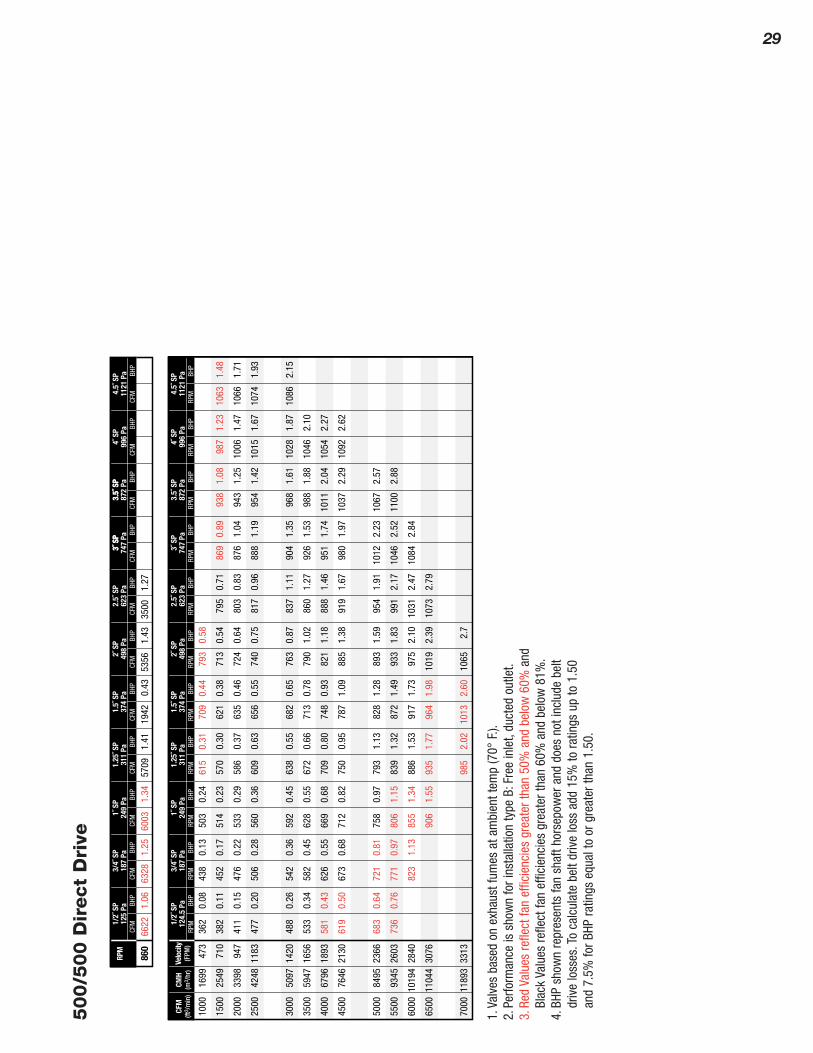
29
500/5
00 D
irect
Dri
ve
Velo
city
(FPM
)CF
M(ft
3 /m
in)
CMH
(m3 /
hr)
872
Pa3.
5˝ S
P99
6 Pa
4˝ S
P11
21 P
a4.
5˝ S
P37
4 Pa
1.5˝
SP
498
Pa2˝
SP
623
Pa2.
5˝ S
P74
7 Pa
3˝ S
P12
4.5
Pa1/
2˝ S
P18
7 Pa
3/4˝
SP
249
Pa1˝
SP
311
Pa1.
25˝ S
P
RPM
BHP
RPM
BHP
RPM
BHP
RPM
BHP
RPM
BHP
RPM
BHP
RPM
BHP
RPM
BHP
RPM
BHP
RPM
872
Pa3.
5˝ S
P37
4 Pa
1.5˝
SP
498
Pa2˝
SP
623
Pa2.
5˝ S
P74
7 Pa
3˝ S
P12
5 Pa
1/2˝
SP
187
Pa3/
4˝ S
P24
9 Pa
1˝ S
P31
1 Pa
1.25
˝ SP
CFM
BHP
CFM
BHP
CFM
BHP
CFM
BHP
CFM
BHP
CFM
BHP
CFM
BHP
CFM
BHP
CFM
BHP
RPM
BHP
RPM
BHP
3.5˝
SP
996
Pa4˝
SP
1121
Pa
4.5˝
SP
3˝ S
P
CFM
BHP
CFM
BHP
362
0.08
438
0.13
503
0.24
1000
1699
473
615
0.31
709
0.44
793
0.58
1063
1.48
987
1.23
382
0.11
938
1.08
452
0.17
869
0.89
514
0.23
795
0.71
1500
2549
710
570
0.30
621
0.38
713
0.54
1066
1.71
1006
1.47
411
0.15
943
1.25
476
0.22
876
1.04
533
0.29
803
0.83
2000
3398
947
586
0.37
635
0.46
724
0.64
1074
1.93
1015
1.67
477
0.20
954
1.42
506
0.28
888
1.19
560
0.36
817
0.96
2500
4248
1183
609
0.63
656
0.55
740
0.75
1086
2.15
1028
1.87
488
0.26
968
1.61
542
0.36
904
1.35
592
0.45
837
1.11
3000
5097
1420
638
0.55
682
0.65
763
0.87
1046
2.10
533
0.34
988
1.88
582
0.45
926
1.53
628
0.55
860
1.27
3500
5947
1656
672
0.66
713
0.78
790
1.02
1054
2.27
581
0.43
1011
2.04
626
0.55
951
1.74
669
0.68
888
1.46
4000
6796
1893
709
0.80
748
0.93
821
1.18
1092
2.62
619
0.50
1037
2.29
673
0.68
980
1.97
712
0.82
919
1.67
4500
7646
2130
750
0.95
787
1.09
885
1.38
683
0.64
1067
2.57
721
0.81
1012
2.23
758
0.97
954
1.91
5000
8495
2366
793
1.13
828
1.28
893
1.59
736
0.76
1100
2.88
771
0.97
1046
2.52
806
1.15
991
2.17
5500
9345
2603
839
1.32
872
1.49
933
1.83
823
1.13
1084
2.84
855
1.34
1031
2.47
6000
1019
428
4088
61.
5391
71.
7397
52.
10
906
1.55
1073
2.79
6500
1104
430
7693
51.
7796
41.
9810
192.
39
7000
1189
333
1398
52.
0210
132.
6010
652.
7
860
6622
1.06
6328
1.25
6003
1.34
5709
1.41
1942
0.43
5356
1.43
3500
1.27
1.Va
lves
bas
ed o
n ex
haus
t fum
es a
t am
bien
t tem
p (7
0°F.
).2.
Perfo
rman
ce is
sho
wn
for i
nsta
llatio
n ty
pe B
:Fre
e in
let,
duct
ed o
utle
t.3.
Red
Valu
es re
flect
fan
effic
ienc
ies
grea
ter t
han
50%
and
bel
ow 6
0%an
dBl
ack
Valu
es re
flect
fan
effic
ienc
ies
grea
ter t
han
60%
and
bel
ow 8
1%.
4.BH
P sh
own
repr
esen
ts fa
n sh
aft h
orse
pow
er a
nd d
oes
not i
nclu
de b
elt
driv
e lo
sses
.To
calc
ulat
e be
lt dr
ive
loss
add
15%
to ra
tings
up
to 1
.50
and
7.5%
for B
HP ra
tings
equ
al to
or g
reat
er th
an 1
.50.

CORROSION RESISTANTVENTILATION PRODUCTS
TORONTO (Head Office)2175-A Teston Road
Maple (Toronto), Ontario L6A 1T3CANADA
Tel: (905) 832-0600Fax: (905) 832-0992
E-mail: [email protected]
VANCOUVER9511 - 194A Street
Surrey, British Columbia V4N 4G4CANADA
Tel: (604) 882-1564Fax: (604) 882-1432
E-mail: [email protected]
MONTREAL16 Ronald Drive
Montreal West, Quebec H4X 1M8CANADA
Phone: (514) 369-6600Fax: (514) 369-5736
E-Mail: [email protected]
EDMONTON12938 - 148 Street
Edmonton, Alberta T5L 2H8CANADA
Tel: (780) 451-0238Fax: (780) 455-4816
E-mail: [email protected]
FABCO PLASTICS WHOLESALE (ONTARIO) LIMITED
Distrubuted By
www.fabcoplastics.com
IAPDINTERNATIONAL ASSOCIATION OF PLASTICS DISTRIBUTORS
Related Documents