CENTERLINE ® Motor Control Centers Mains and Incoming Lines Dimension Reference Document Update Description This publication provides updates to Mains and Incoming Lines Dimension Reference, publication 2100-4.2, dated October, 1998. Please place this document in your manual for future reference. Introduction Footnote has been changed for all pages where found within the publication. The new footnote is to be: Optional ground bus location. Note - The front face of the 1/4” ground bus is located at 7.25 [184] from the cabinet front. Incoming cable pull may not be correctly represented in the diagram. Publication 2100-4.2DU1 - March, 1999

Welcome message from author
This document is posted to help you gain knowledge. Please leave a comment to let me know what you think about it! Share it to your friends and learn new things together.
Transcript

CENTERLINE® Motor Control Centers Mains and Incoming Lines Dimension Reference
Document Update
Description This publication provides updates to Mains and Incoming Lines Dimension Reference, publication 2100-4.2, dated October, 1998. Please place this document in your manual for future reference.
Introduction Footnote ��has been changed for all pages where found within the publication. The new footnote is to be:
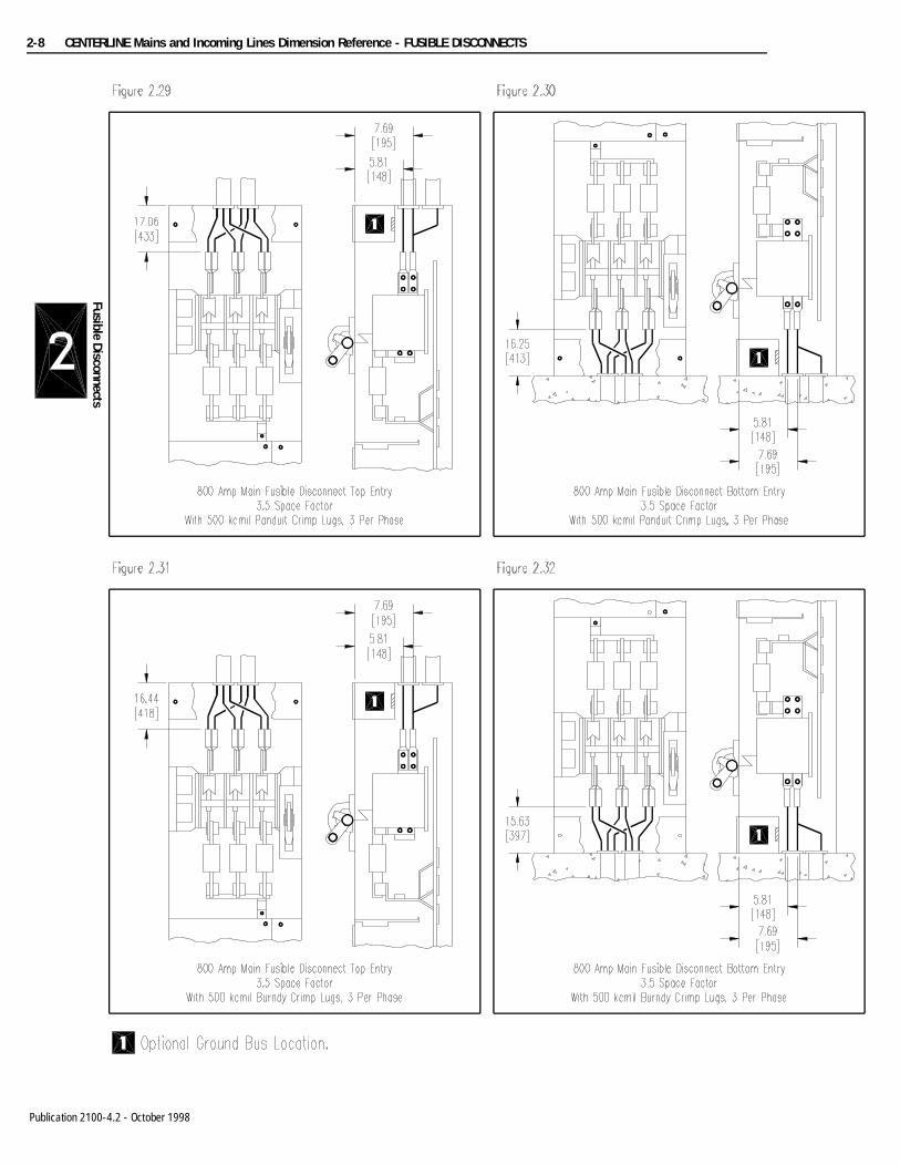
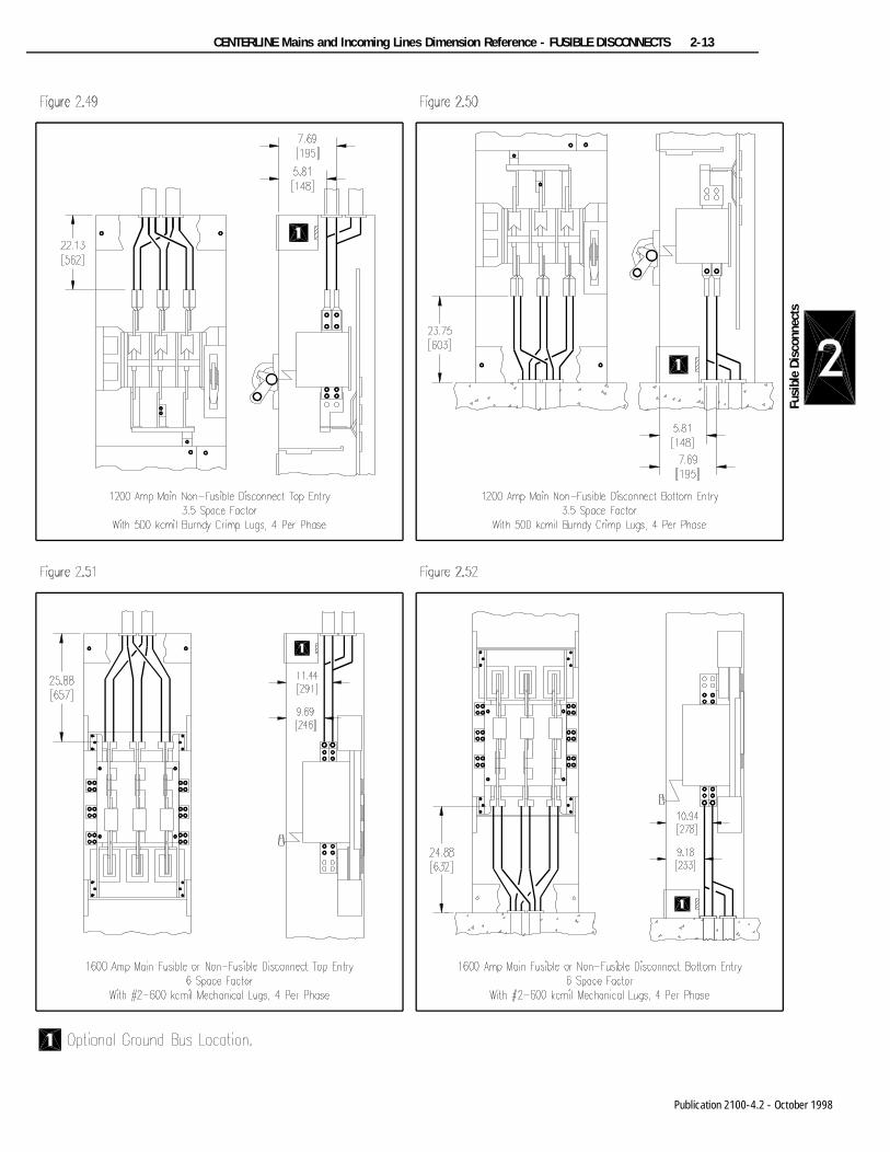
� Optional ground bus location. Note - The front face of the 1/4” ground bus is located at 7.25 [184] from the cabinet front. Incoming cable pullmay not be correctly represented in the diagram.
Publication 2100-4.2DU1 - March, 1999

Mains and Incoming Lines Dimension Reference
Bulletin 2100CENTERLINE®
Motor ControlCenters
(Cat. No. 2100-4.2)
Allen-Bradley

Table of Contents
Lug Compartment...................................................... 1-1
Main Fusible Disconnects......................................... 2-1
Main Circuit Breakers............................................... 3-1
Conduit Entry............................................................... 4-1
300 AMP............................................................................... 1-1
600 AMP............................................................................... 1-1800 AMP............................................................................... 1-11200 AMP............................................................................. 1-2
1600 AMP............................................................................. 1-22000 AMP............................................................................. 1-4Corner Incoming Line Sections............................................ 1-5
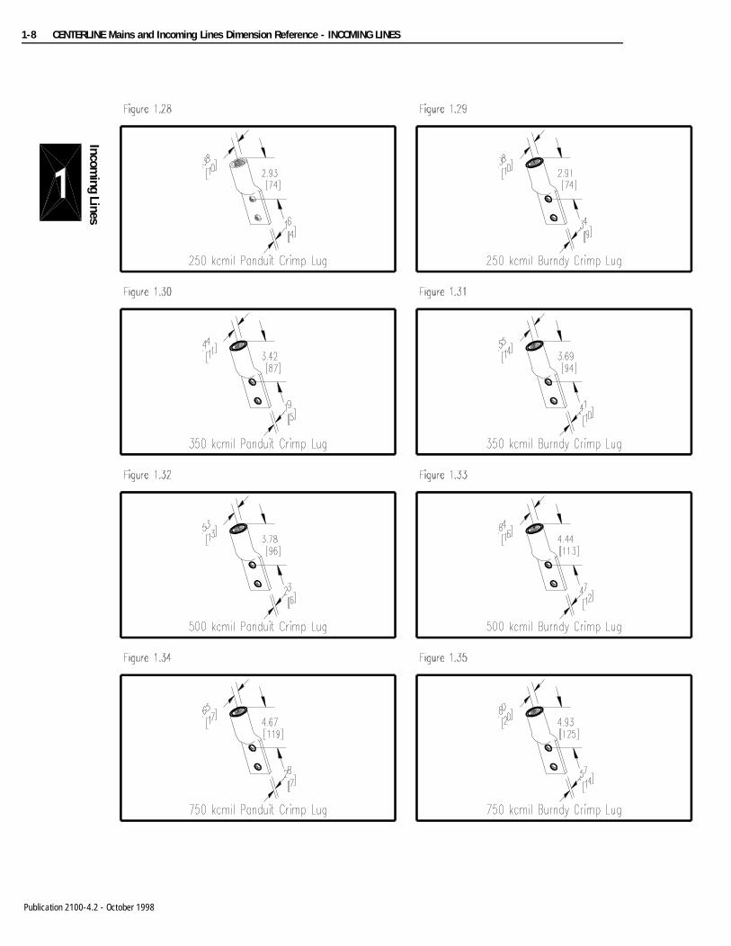
10” Wide Incoming Line Sections......................................... 1-6Mechanical Lugs.................................................................. 1-7Panduit and Burndy Crimp Lugs............................................ 1-8
30 AMP................................................................................. 2-1
60 AMP................................................................................. 2-1100 AMP............................................................................... 2-2
200 AMP............................................................................... 2-2400 AMP............................................................................... 2-3600 AMP............................................................................... 2-4
800 AMP............................................................................... 2-71200 AMP............................................................................. 2-101600 AMP............................................................................. 2-13
2000 AMP............................................................................. 2-15
150 AMP............................................................................... 3-1
225 AMP............................................................................... 3-1
400 AMP............................................................................... 3-2600 AMP............................................................................... 3-4800 AMP............................................................................... 3-5
1200 AMP............................................................................. 3-102000 AMP............................................................................. 3-14
Top Entry.............................................................................. 4-1
Bottom Entry........................................................................ 4-4Bottom Entry with External Mounting Channels.................... 4-7

toc–iii Table of Contents
Publication xxxx-xx.x - Month 19xx

CENTERLINE® Motor Control CentersMains and Incoming Lines Dimension Reference
Application Notes
Application This guide contains cabling dimensions for main incoming line compartments, fusible disconnect switch mains, and circuit breaker mains in Bulletin 2100 CENTERLINE motor control centers. Lug pad dimensions are included for main incoming line compartments. The fusible disconnect and circuit breaker mains drawing include dimensions for standard lugs, and optional lugs (if specified).
Important: Although this guide was accurate at the time of printing, there may be differences between these drawings and the actual product, due to recent design enhancements. Always refer to Allen-Bradley Job- Specific Drawings (Form 385) for the most accurate drawings and dimensions.
Important: Reference dimensions include a tolerance of ±1/8 inches (3.2 mm).
Catalog Numbers Every CENTERLINE motor control center unit is defined by a catalog number. For mains, these catalog numbers are of the following form.
The catalog numbers appear on the unit label, located on the unit bottom plate. For assembled motor control centers, catalog numbers for each unit are also listed on the Allen-Bradley Job-Specific Drawings (Form 385), that ships with the order.
For more information about catalog numbering, refer to publication 2100-3.0, Bulletin 2100 price book.
Additional References
• 2100-1.0 - CENTERLINE Bulletin 2100 brochure
• 2100-3.0 - CENTERLINE Bulletin 2100 price book
• Form 385 - Motor Control Center Layout and Specification
Type of Main Catalog Bulletin Number Catalog Number Example
Incoming Line 2191M 2191MT-CAC-54
Fusible Disconnect 2192M 2192MB-GAC-29R
Circuit Breaker 2193M 2193MT-FJC-54WT-83C500

Publication 2100-5.42 - October 1998

CENTERLINE Mains and Incoming Lines Dimension Reference - INCOMING LINES 1-1
Inco
min
g Li
nes
Publication 2100-4.2 - October 1998

1-2 CENTERLINE Mains and Incoming Lines Dimension Reference - INCOMING LINES
Incoming Lines
Publication 2100-4.2 - October 1998

CENTERLINE Mains and Incoming Lines Dimension Reference - INCOMING LINES 1-3
Inco
min
g Li
nes
Publication 2100-4.2 - October 1998

1-4 CENTERLINE Mains and Incoming Lines Dimension Reference - INCOMING LINES
Incoming Lines
Publication 2100-4.2 - October 1998

CENTERLINE Mains and Incoming Lines Dimension Reference - INCOMING LINES 1-5
Inco
min
g Li
nes
Publication 2100-4.2 - October 1998

1-6 CENTERLINE Mains and Incoming Lines Dimension Reference - INCOMING LINES
Incoming Lines
Publication 2100-4.2 - October 1998

CENTERLINE Mains and Incoming Lines Dimension Reference - INCOMING LINES 1-7
Inco
min
g Li
nes
Publication 2100-4.2 - October 1998
1-8 CENTERLINE Mains and Incoming Lines Dimension Reference - INCOMING LINES
Incoming Lines
Publication 2100-4.2 - October 1998

CENTERLINE Mains and Incoming Lines Dimension Reference - FUSIBLE DISCONNECTS 2-1
Fusi
ble
Disc
onne
cts
Publication 2100-4.2 - October 1998

2-2 CENTERLINE Mains and Incoming Lines Dimension Reference - FUSIBLE DISCONNECTS
Fusible Disconnects
Publication 2100-4.2 - October 1998

CENTERLINE Mains and Incoming Lines Dimension Reference - FUSIBLE DISCONNECTS 2-3
Fusi
ble
Disc
onne
cts
Publication 2100-4.2 - October 1998

2-4 CENTERLINE Mains and Incoming Lines Dimension Reference - FUSIBLE DISCONNECTS
Fusible Disconnects
Publication 2100-4.2 - October 1998

CENTERLINE Mains and Incoming Lines Dimension Reference - FUSIBLE DISCONNECTS 2-5
Fusi
ble
Disc
onne
cts
Publication 2100-4.2 - October 1998

2-6 CENTERLINE Mains and Incoming Lines Dimension Reference - FUSIBLE DISCONNECTS
Fusible Disconnects
Publication 2100-4.2 - October 1998

CENTERLINE Mains and Incoming Lines Dimension Reference - FUSIBLE DISCONNECTS 2-7
Fusi
ble
Disc
onne
cts
Publication 2100-4.2 - October 1998
2-8 CENTERLINE Mains and Incoming Lines Dimension Reference - FUSIBLE DISCONNECTS
Fusible Disconnects
Publication 2100-4.2 - October 1998

CENTERLINE Mains and Incoming Lines Dimension Reference - FUSIBLE DISCONNECTS 2-9
Fusi
ble
Dis
conn
ects
Publication 2100-4.2 - October 1998

2-10 CENTERLINE Mains and Incoming Lines Dimension Reference - FUSIBLE DISCONNECTS
Fusible Disconnects
Publication 2100-4.2 - October 1998

CENTERLINE Mains and Incoming Lines Dimension Reference - FUSIBLE DISCONNECTS 2-11
Fusi
ble
Disc
onne
cts
Publication 2100-4.2 - October 1998

2-12 CENTERLINE Mains and Incoming Lines Dimension Reference - FUSIBLE DISCONNECTS
Fusible Disconnects
Publication 2100-4.2 - October 1998
CENTERLINE Mains and Incoming Lines Dimension Reference - FUSIBLE DISCONNECTS 2-13
Fusi
ble
Disc
onne
cts
Publication 2100-4.2 - October 1998

2-14 CENTERLINE Mains and Incoming Lines Dimension Reference - FUSIBLE DISCONNECTS
Fusible Disconnects
Publication 2100-4.2 - October 1998
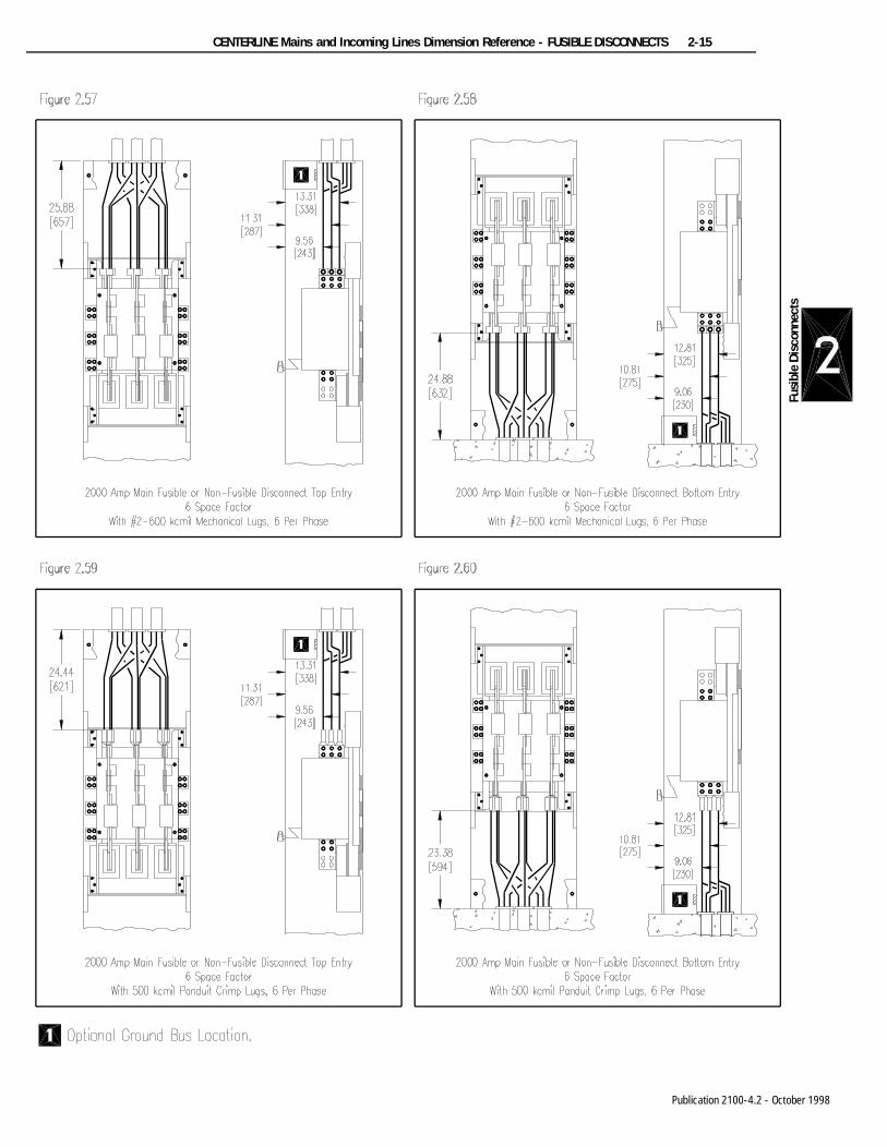
CENTERLINE Mains and Incoming Lines Dimension Reference - FUSIBLE DISCONNECTS 2-15
Fusi
ble
Dis
conn
ects
Publication 2100-4.2 - October 1998
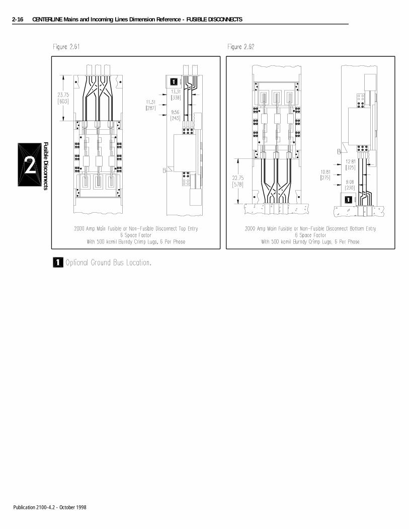
2-16 CENTERLINE Mains and Incoming Lines Dimension Reference - FUSIBLE DISCONNECTS
Fusible Disconnects
Publication 2100-4.2 - October 1998
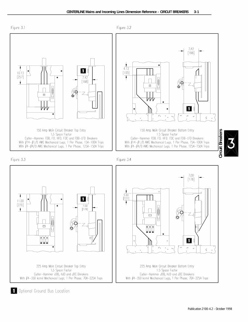
CENTERLINE Mains and Incoming Lines Dimension Reference - CIRCUIT BREAKERS 3-1
Circ
uit B
reak
ers
Publication 2100-4.2 - October 1998

3-2 CENTERLINE Mains and Incoming Lines Dimension Reference - CIRCUIT BREAKERS
Circuit Breakers
Publication 2100-4.2 - October 1998

CENTERLINE Mains and Incoming Lines Dimension Reference - CIRCUIT BREAKERS 3-3
Circ
uit B
reak
ers
Publication 2100-4.2 - October 1998

3-4 CENTERLINE Mains and Incoming Lines Dimension Reference - CIRCUIT BREAKERS
Circuit Breakers
Publication 2100-4.2 - October 1998

CENTERLINE Mains and Incoming Lines Dimension Reference - CIRCUIT BREAKERS 3-5
Circ
uit B
reak
ers
Publication 2100-4.2 - October 1998

3-6 CENTERLINE Mains and Incoming Lines Dimension Reference - CIRCUIT BREAKERS
Circuit Breakers
Publication 2100-4.2 - October 1998
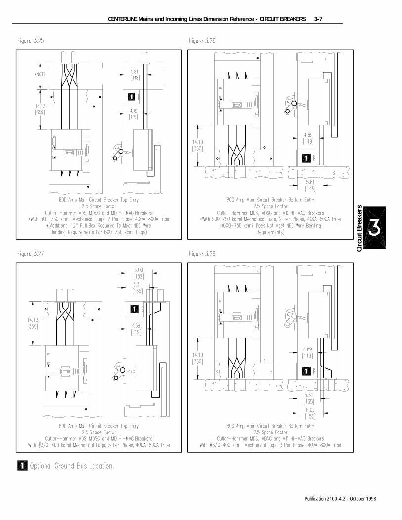
CENTERLINE Mains and Incoming Lines Dimension Reference - CIRCUIT BREAKERS 3-7
Circ
uit B
reak
ers
Publication 2100-4.2 - October 1998

3-8 CENTERLINE Mains and Incoming Lines Dimension Reference - CIRCUIT BREAKERS
Circuit Breakers
Publication 2100-4.2 - October 1998

CENTERLINE Mains and Incoming Lines Dimension Reference - CIRCUIT BREAKERS 3-9
Circ
uit B
reak
ers
Publication 2100-4.2 - October 1998

3-10 CENTERLINE Mains and Incoming Lines Dimension Reference - CIRCUIT BREAKERS
Circuit Breakers
Publication 2100-4.2 - October 1998

CENTERLINE Mains and Incoming Lines Dimension Reference - CIRCUIT BREAKERS 3-11
Circ
uit B
reak
ers
Publication 2100-4.2 - October 1998
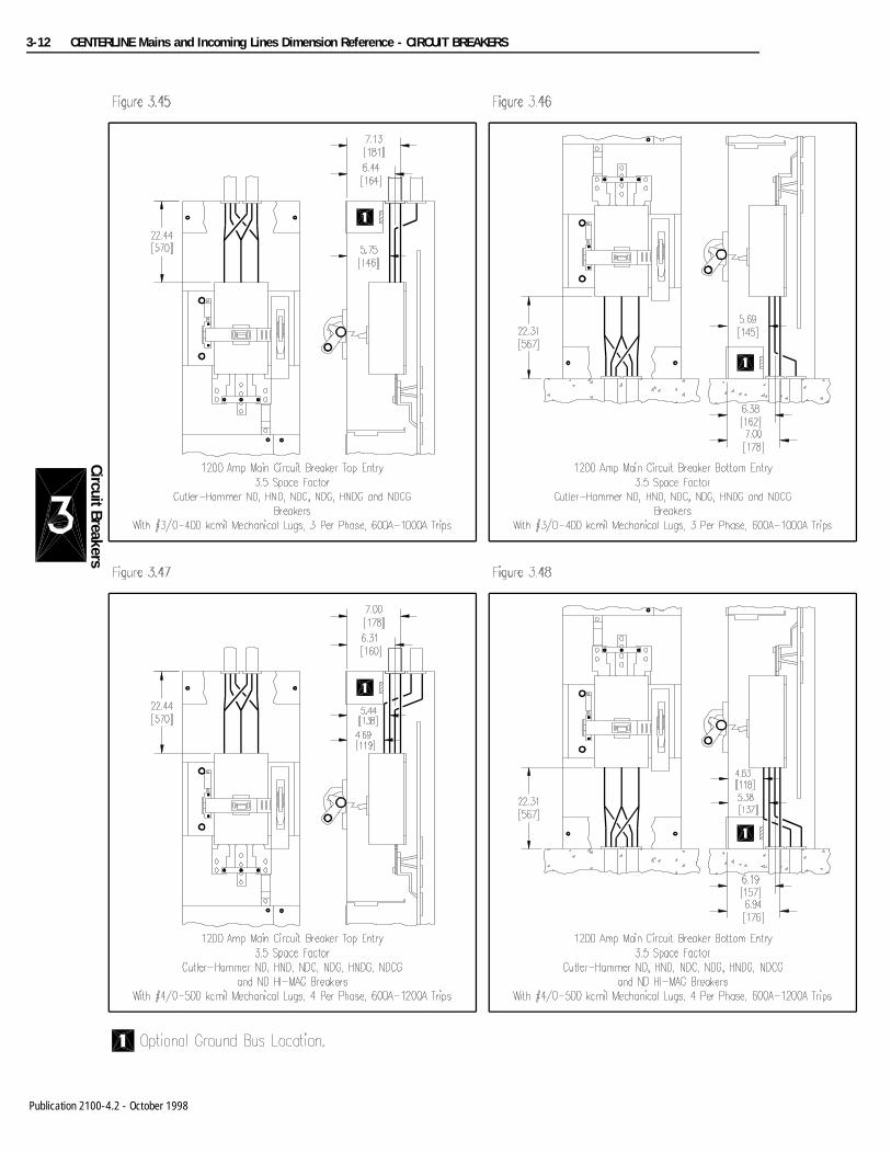
3-12 CENTERLINE Mains and Incoming Lines Dimension Reference - CIRCUIT BREAKERS
Circuit Breakers
Publication 2100-4.2 - October 1998
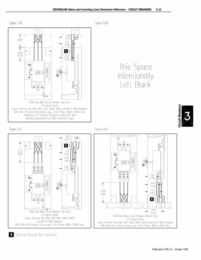
CENTERLINE Mains and Incoming Lines Dimension Reference - CIRCUIT BREAKERS 3-13
Circ
uit B
reak
ers
Publication 2100-4.2 - October 1998

3-14 CENTERLINE Mains and Incoming Lines Dimension Reference - CIRCUIT BREAKERS
Circuit Breakers
Publication 2100-4.2 - October 1998

CENTERLINE Mains and Incoming Lines Dimension Reference - CIRCUIT BREAKERS 3-15
Circ
uit B
reak
ers
Publication 2100-4.2 - October 1998

3-16 CENTERLINE Mains and Incoming Lines Dimension Reference - CIRCUIT BREAKERS
Circuit Breakers
Publication 2100-4.2 - October 1998

CENTERLINE Mains and Incoming Lines Dimension Reference - CONDUIT ENTRY 4-1
Cond
uit E
ntry
- To
p
Publication 2100-4.2 - October 1998

4-2 CENTERLINE Mains and Incoming Lines Dimension Reference - CONDUIT ENTRY
Conduit Entry - Top
Publication 2100-4.2 - October 1998

CENTERLINE Mains and Incoming Lines Dimension Reference - CONDUIT ENTRY 4-3
Cond
uit E
ntry
- To
p
Publication 2100-4.2 - October 1998

4-4 CENTERLINE Mains and Incoming Lines Dimension Reference - CONDUIT ENTRY
Conduit Entry - Bottom
Publication 2100-4.2 - October 1998

CENTERLINE Mains and Incoming Lines Dimension Reference - CONDUIT ENTRY 4-5
Cond
uit E
ntry
- B
otto
m
Publication 2100-4.2 - October 1998

4-6 CENTERLINE Mains and Incoming Lines Dimension Reference - CONDUIT ENTRY
Conduit Entry - Bottom
Publication 2100-4.2 - October 1998

CENTERLINE Mains and Incoming Lines Dimension Reference - CONDUIT ENTRY 4-7
Cond
uit E
ntry
- B
otto
m
Publication 2100-4.2 - October 1998

4-8 CENTERLINE Mains and Incoming Lines Dimension Reference - CONDUIT ENTRY
Conduit Entry - Bottom
Publication 2100-4.2 - October 1998
Related Documents