Chapter 3 Moments & Parallel Coplanar Forces

Welcome message from author
This document is posted to help you gain knowledge. Please leave a comment to let me know what you think about it! Share it to your friends and learn new things together.
Transcript
Chapter 3
Moments & Parallel Coplanar Forces
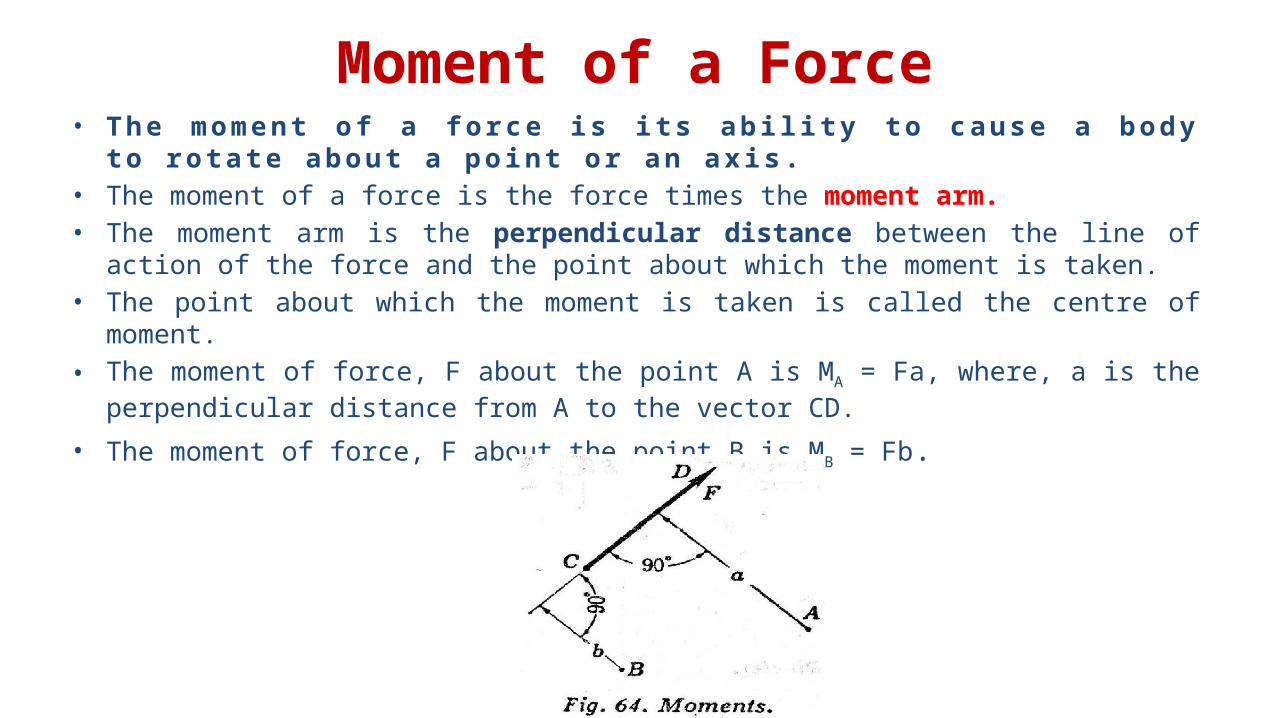
Moment of a Force• The moment of a force is its ability to cause a body
to rotate about a point or an axis. • The moment of a force is the force times the moment arm. • The moment arm is the perpendicular distance between the line of
action of the force and the point about which the moment is taken. • The point about which the moment is taken is called the centre of
moment.• The moment of force, F about the point A is MA = Fa, where, a is the
perpendicular distance from A to the vector CD.• The moment of force, F about the point B is MB = Fb.
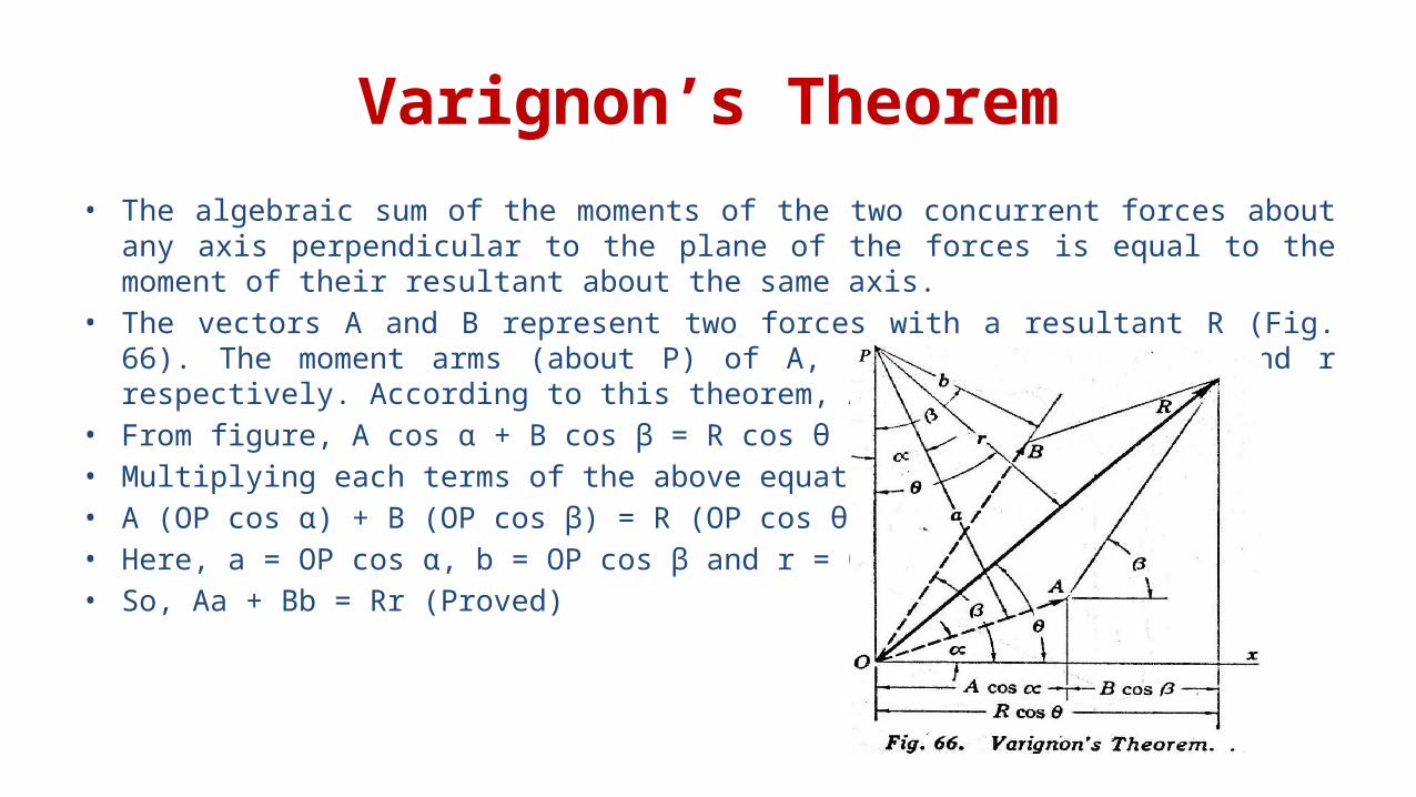
Varignon’s Theorem• The algebraic sum of the moments of the two concurrent forces about
any axis perpendicular to the plane of the forces is equal to the moment of their resultant about the same axis.
• The vectors A and B represent two forces with a resultant R (Fig. 66). The moment arms (about P) of A, B, and R are a, b, and r respectively. According to this theorem, Aa + Bb = Rr
• From figure, A cos α + B cos β = R cos θ• Multiplying each terms of the above equation by OP,• A (OP cos α) + B (OP cos β) = R (OP cos θ)• Here, a = OP cos α, b = OP cos β and r = OP cos θ• So, Aa + Bb = Rr (Proved)
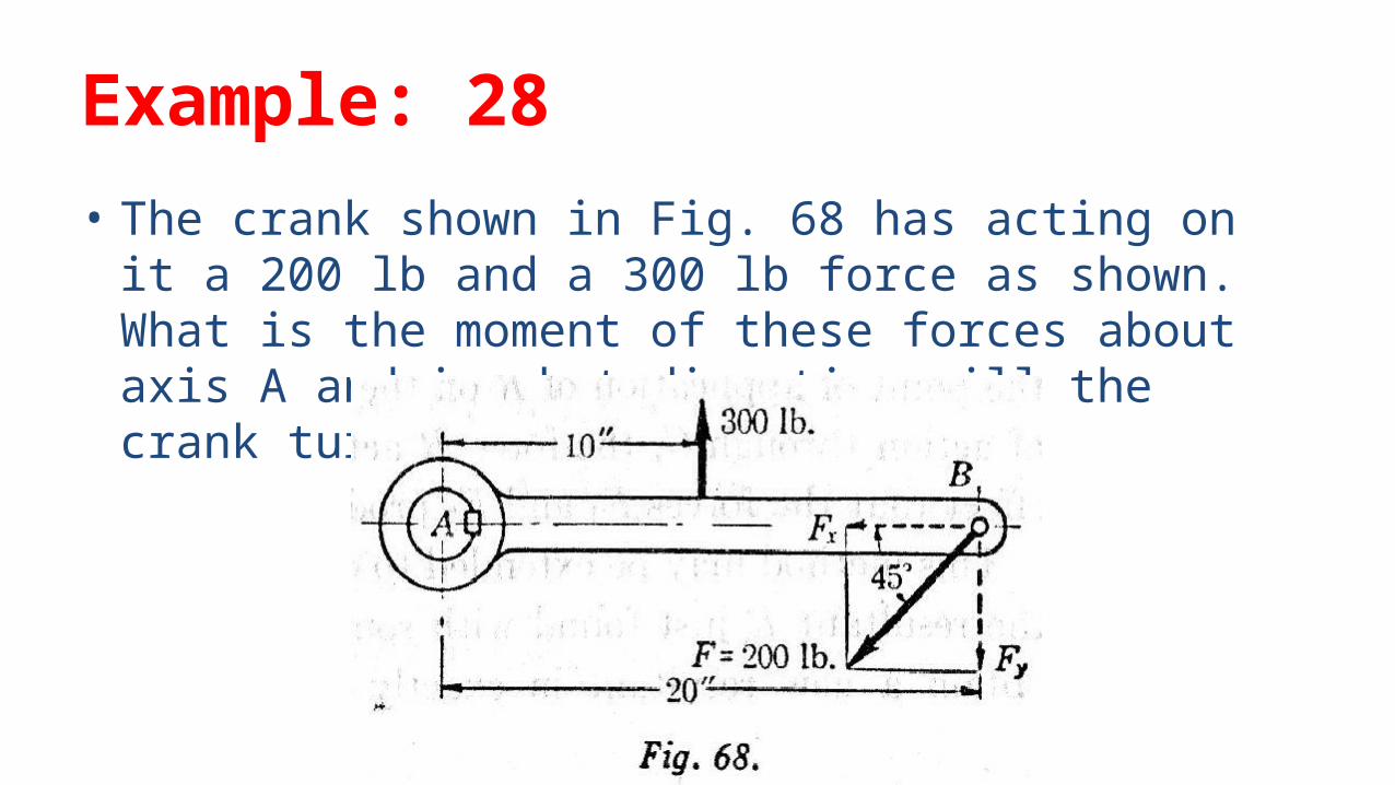
Example: 28• The crank shown in Fig. 68 has acting on it a 200 lb and a 300 lb force as shown. What is the moment of these forces about axis A and in what direction will the crank turn?

Resultant of Parallel Coplanar Forces
• The algebric sum of the moments of any number of coplanar parallel forces about any point in their plane is equal to their moment of their resultant about the same point.
• Varignon’s Theorem points to the same conclusion.
• See page 45-47 of Analytic Mechanics by Faires & Chambers for more details.
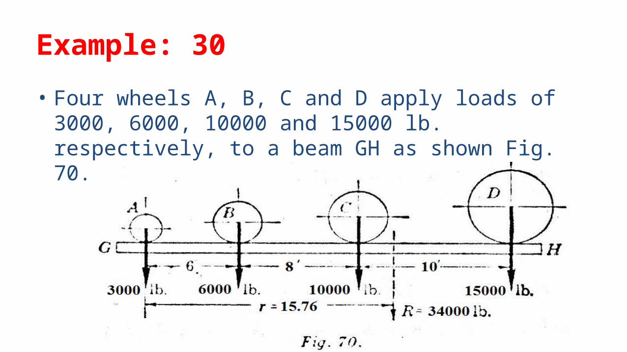
Example: 30• Four wheels A, B, C and D apply loads of 3000, 6000, 10000 and 15000 lb. respectively, to a beam GH as shown Fig. 70. Find the resultant of these loads.
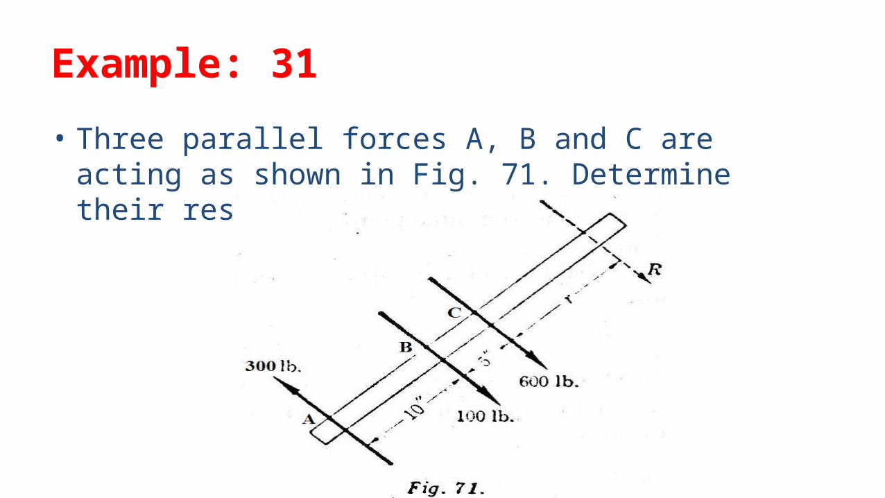
Example: 31• Three parallel forces A, B and C are acting as shown in Fig. 71. Determine their resultant.
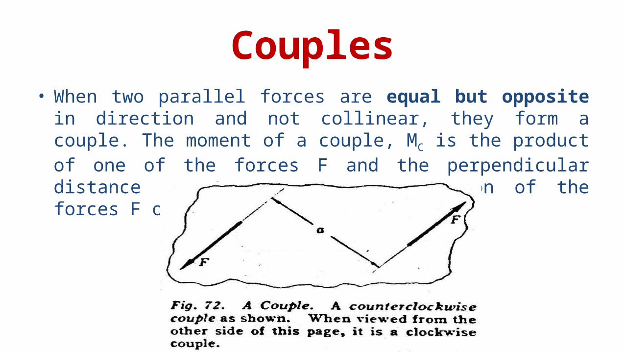
Couples• When two parallel forces are equal but opposite in direction and not collinear, they form a couple. The moment of a couple, MC is the product of one of the forces F and the perpendicular distance between the lines of action of the forces F or MC = Fa.
Resultant of a Coplanar Parallel Force System in which F = 0∑
• If a system of parallel coplanar forces is not in equilibrium but F (in the ∑direction of forces) = 0, then the resultant is a couple.
• The magnitude and sense of the couple may be obtained by taking moments about any convenient point.
Equilibrium of Coplanar Parallel Forces
•∑Fx = 0
•∑Fy = 0
•∑M = 0
Types of Contacts/Supports• Flexible cable or rope• Smooth Surface• Rough Surface• Roller Support/ Simple Support• Pinned Support/ Hinged Support• Fixed Support
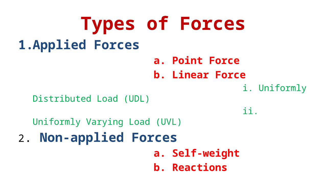
Types of Forces1.Applied Forces a. Point Force b. Linear Force i. Uniformly
Distributed Load (UDL) ii.
Uniformly Varying Load (UVL)2. Non-applied Forces a. Self-weight b. Reactions
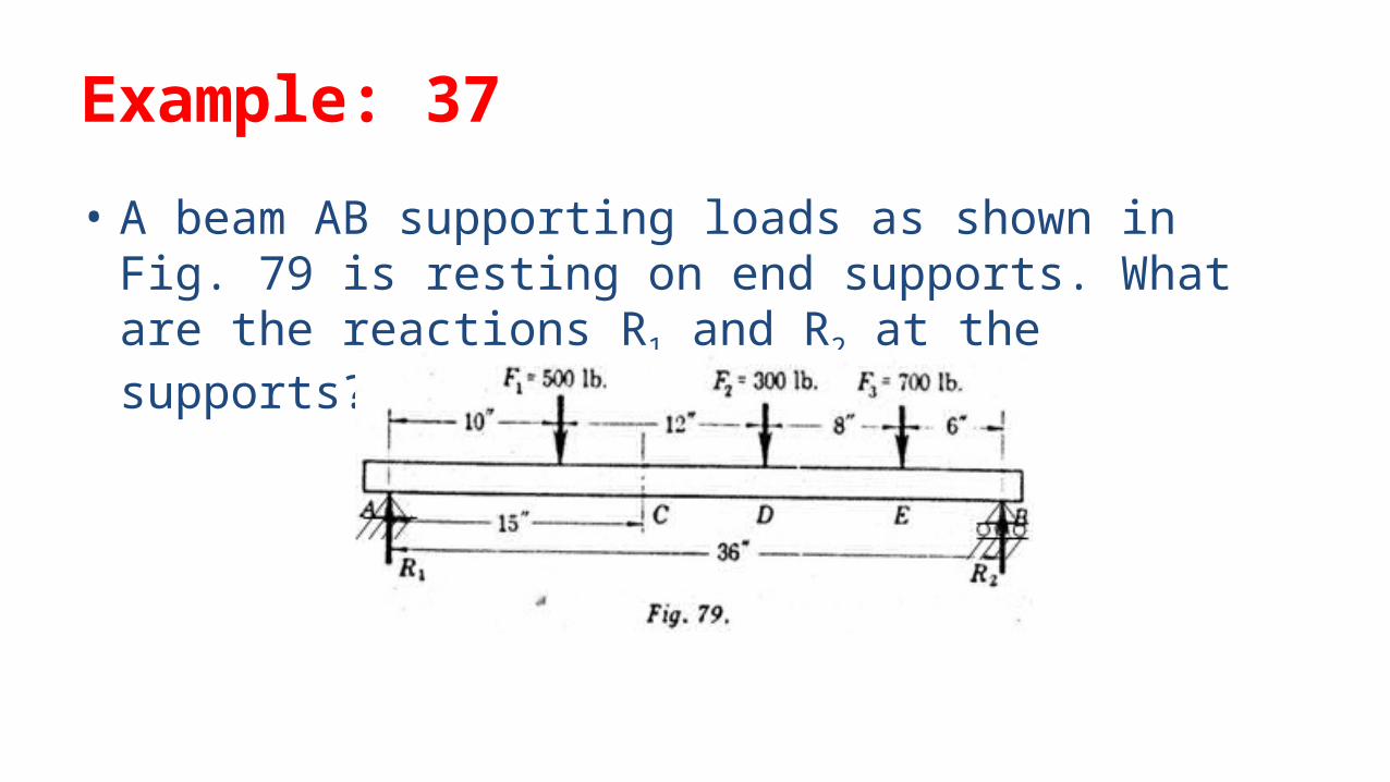
Example: 37• A beam AB supporting loads as shown in Fig. 79 is resting on end supports. What are the reactions R1 and R2 at the supports?
Moment and Shear at a section• The Shear Force at the cross section of the beam may be defined as the unbalanced vertical force to the right or left of the section.
• The Bending Moment at the cross section of the beam may be defined as the algebraic sum of the moments of the forces, to the right or left of the section.
• See Section 38, Page 54-55 from Analytic Mechanics by Faires & Chambers for details
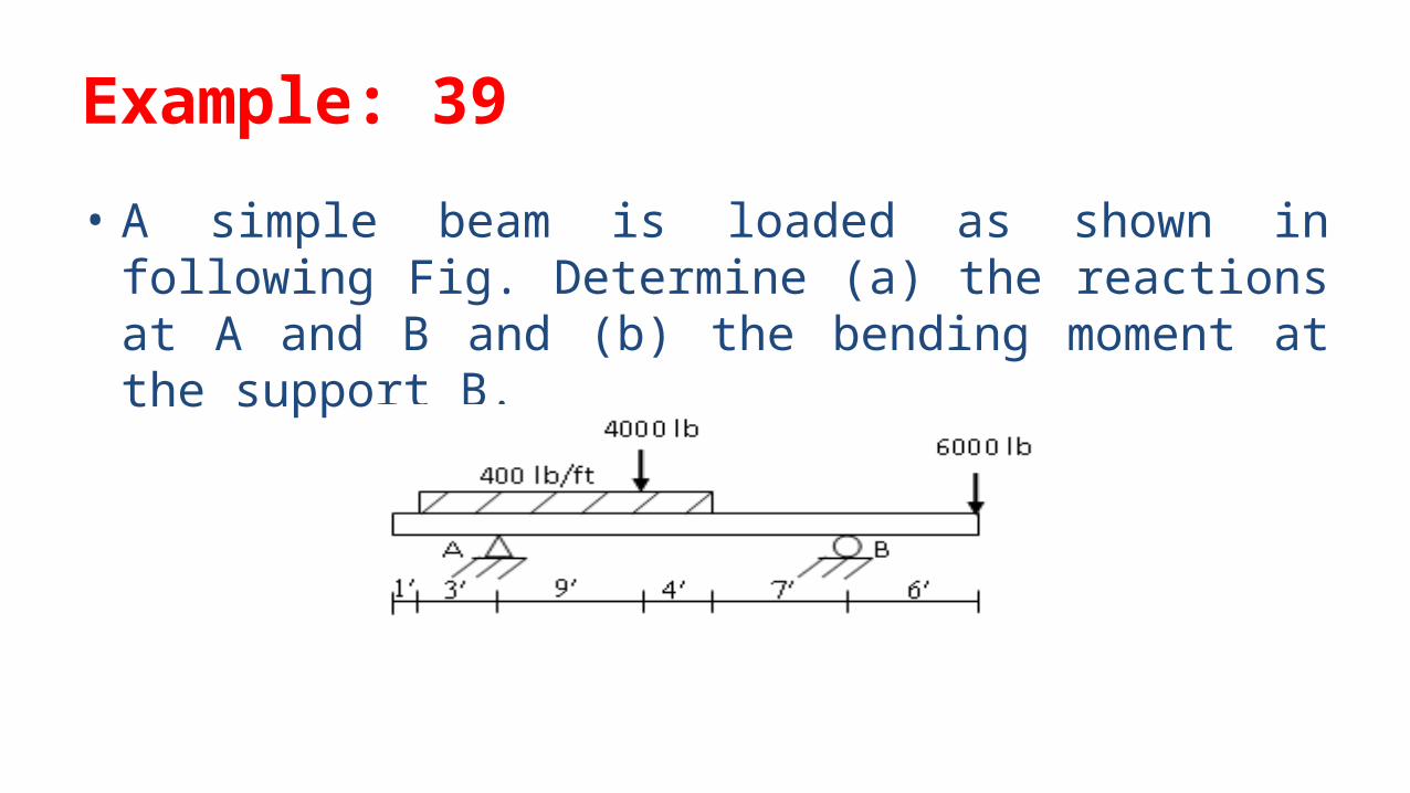
Example: 39• A simple beam is loaded as shown in following Fig. Determine (a) the reactions at A and B and (b) the bending moment at the support B.
Closure• The moment arm of a force is always perpendicular to the line of action of the force.
• The moment of a force has no meaning unless the center of moments is specified.
• It is convenient to use the moments of rectangular components of a force in place of the moment of the force itself.
• There are two independent conditions for a system of coplanar parallel forces in equilibrium, F = 0 and M = 0.∑ ∑
• When two unknown forces in a group of coplanar parallel forces in equilibrium are to be found, it is advisable to find each force by a moment equation, so that F = 0 can be ∑used as a check on the computations.
ASSIGNMENTS
Problem 171, 178, 200, 205, 207, 209, 213 (Faires and Chambers)
Related Documents