CELLULAR CONCEPT SHUSHRUTHA K S “ Provide additional radio capacity with no additional increase in radio spectrum ”

Welcome message from author
This document is posted to help you gain knowledge. Please leave a comment to let me know what you think about it! Share it to your friends and learn new things together.
Transcript
CELLULAR CONCEPT
SHUSHRUTHA K S
“Provide additional radio capacity with no additional increase in radio spectrum”
INTRODUCTION
• Early mobile radio system was to achieve a large coverage areas by using high powered transmitter with an antenna mounted on a tall tower
• In this case it is impossible to reuse those same frequencies throughout the system
• Since any attempts to achieve frequency reuse would result in interference
Cont..• Cellular concept is a system level idea which calls for
replacing a single , high power transmitter with low power small transmitters with each providing coverage to only a small portion of service area
• Each base station is allocated a portion of total no of channels available to entire system
• Nearby base station are assigned different groups of channels so that all the available channels are assigned to a relatively small no. of neighboring base stations
• Nearby BS are assigned different groups of channel so that interference bt. BS is minimized
THE CELLULAR CONCEPT
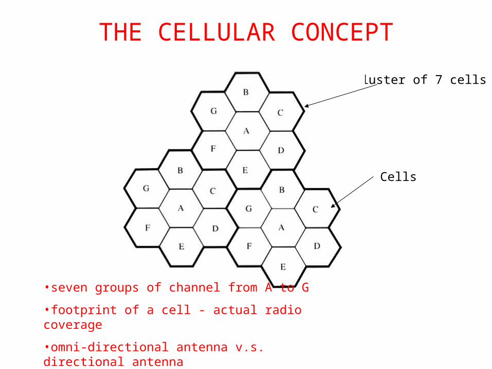
Cluster of 7 cells
Cells
•seven groups of channel from A to G
•footprint of a cell - actual radio coverage
•omni-directional antenna v.s. directional antenna
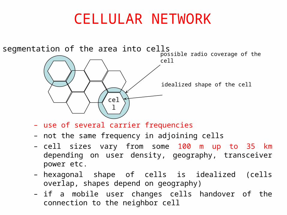
possible radio coverage of the cell
idealized shape of the cell
cell
segmentation of the area into cells
CELLULAR NETWORK
– use of several carrier frequencies
– not the same frequency in adjoining cells
– cell sizes vary from some 100 m up to 35 km depending on user density, geography, transceiver power etc.
– hexagonal shape of cells is idealized (cells overlap, shapes depend on geography)
– if a mobile user changes cells handover of the connection to the neighbor cell
FREQUENCY REUSE• Each cellular base station is allocated a group of radio channels within
a small geographic area called a cell.
• Neighboring cells are assigned different channel groups.
• By limiting the coverage area to within the boundary of the cell, the channel groups may be reused to cover different cells.
• Keep interference levels within tolerable limits.
• Frequency reuse or frequency planning
“The design process of selecting and allocating channel groups for all of the cellular base station within a system is FREQUENCY REUSE/PLANNING”
• Consider a cellular system which has a total of S duplex channels.
• Each cell is allocated a group of k channels, .
• The S channels are divided among N cells.
• The total number of available radio channels
• The N cells which use the complete set of channels is called cluster.
• The cluster can be repeated M times within the system. The total number of channels, C, is used as a measure of capacity
• The capacity is directly proportional to the number of replication M.
• The cluster size, N, is typically equal to 4, 7, or 12.
• Small N is desirable to maximize capacity.
• The frequency reuse factor is given by
Sk
kNS
MSMkNC
N/1
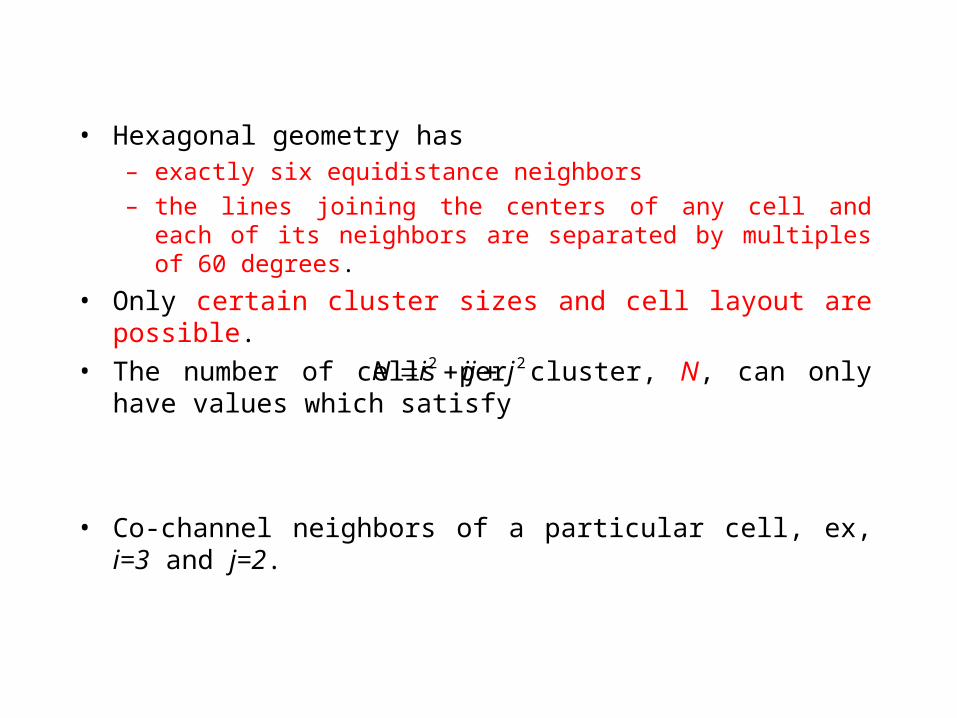
• Hexagonal geometry has – exactly six equidistance neighbors
– the lines joining the centers of any cell and each of its neighbors are separated by multiples of 60 degrees.
• Only certain cluster sizes and cell layout are possible.
• The number of cells per cluster, N, can only have values which satisfy
• Co-channel neighbors of a particular cell, ex, i=3 and j=2.
22 jijiN
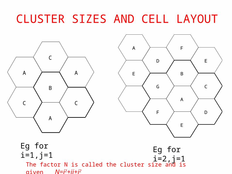
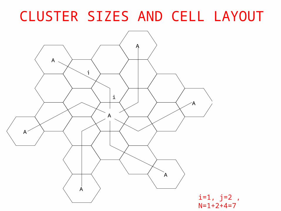
CLUSTER SIZES AND CELL LAYOUT
A
B
C
A
C
A
CA
B
C
A F
E
G
D
E
F
D E
The factor N is called the cluster size and is given N=i2+ij+j2
Eg for i=1,j=1 Eg for i=2,j=1
A
A
A
A
A
A
A
i
j
i=1, j=2 , N=1+2+4=7
CLUSTER SIZES AND CELL LAYOUT
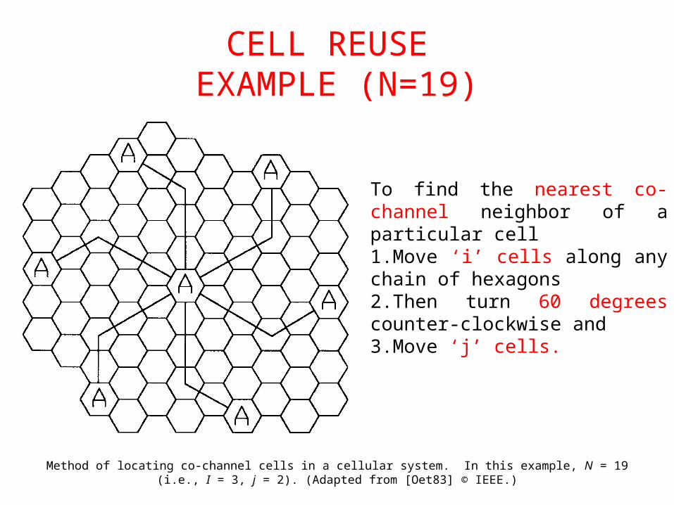
CELL REUSE EXAMPLE (N=19)
Method of locating co-channel cells in a cellular system. In this example, N = 19 (i.e., I = 3, j = 2). (Adapted from [Oet83] © IEEE.)
To find the nearest co-channel neighbor of a particular cell1.Move ‘i’ cells along any chain of hexagons 2.Then turn 60 degrees counter-clockwise and3.Move ‘j’ cells.
ADVANTAGES
• Solves the problem of spectral congestion and user capacity.
• Offer very high capacity in a limited spectrum without major technological changes.
• Reuse of radio channel in different cells.
• Enable a fix number of channels to serve an arbitrarily large number of users by reusing the channel throughout the coverage region.
CAPACITY EXPANSION IN CELLULAR SYSTEM
Techniques to provide more channels per coverage area is by
• Cell splitting• Cell sectoring• Coverage zone approches
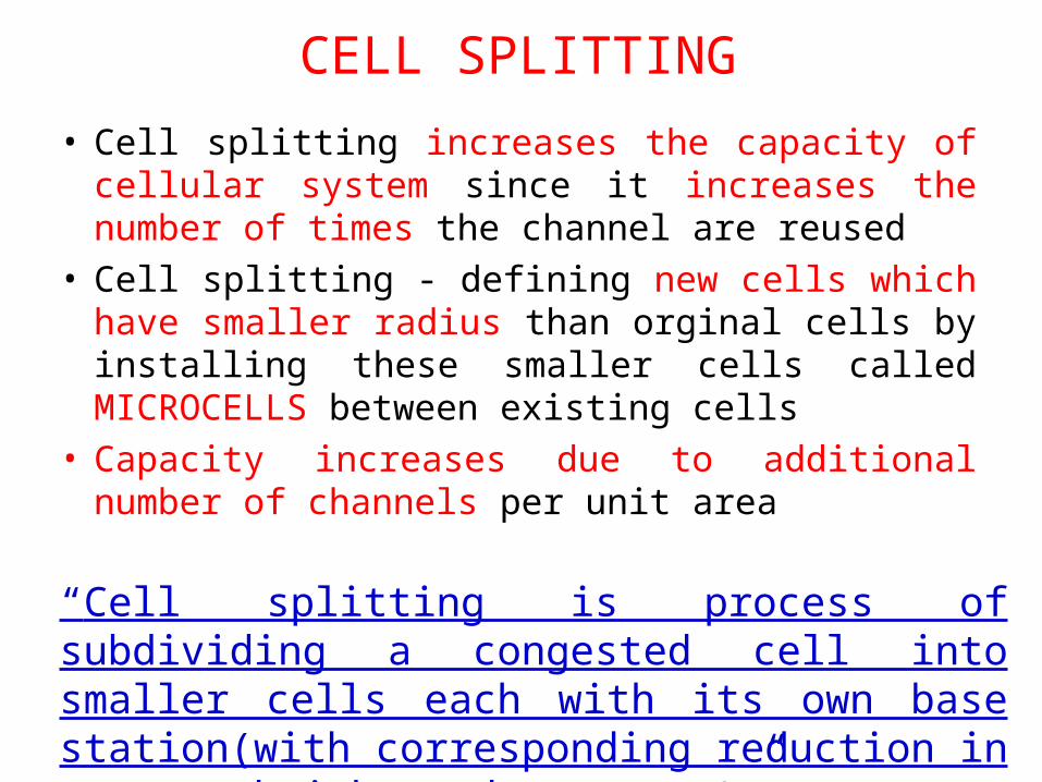
• Cell splitting increases the capacity of cellular system since it increases the number of times the channel are reused
• Cell splitting - defining new cells which have smaller radius than orginal cells by installing these smaller cells called MICROCELLS between existing cells
• Capacity increases due to additional number of channels per unit area
“Cell splitting is process of subdividing a congested cell into smaller cells each with its own base station(with corresponding reduction in antenna height and tx power)”
CELL SPLITTING
CELL SPLITTING
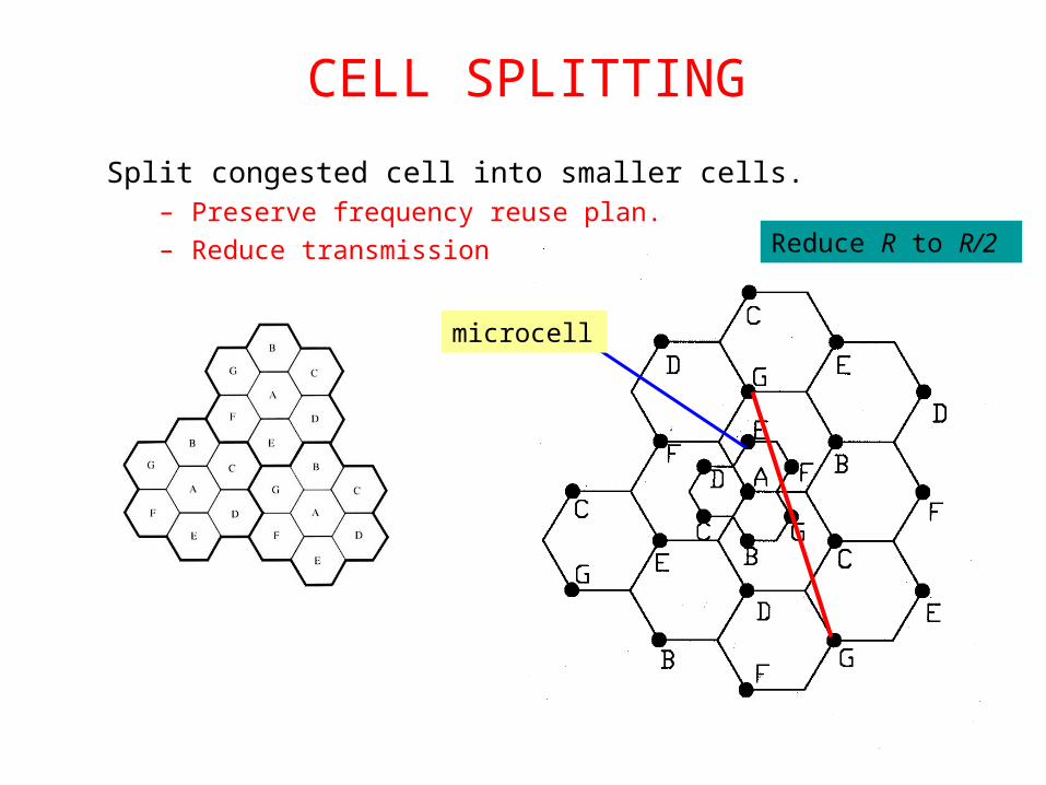
Split congested cell into smaller cells.– Preserve frequency reuse plan.
– Reduce transmission power.
microcell
Reduce R to R/2
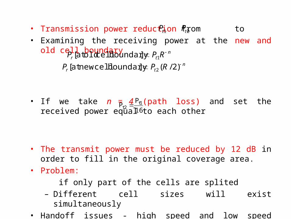
• Transmission power reduction from to
• Examining the receiving power at the new and old cell boundary
• If we take n = 4 (path loss) and set the received power equal to each other
• The transmit power must be reduced by 12 dB in order to fill in the original coverage area.
• Problem:
if only part of the cells are splited
– Different cell sizes will exist simultaneously
• Handoff issues - high speed and low speed traffic can be simultaneously accommodated
1tP 2tP
ntr RPP 1]boundary cell oldat [
ntr RPP )2/(]boundary cellnew at [ 2
16
PP 1t
2t
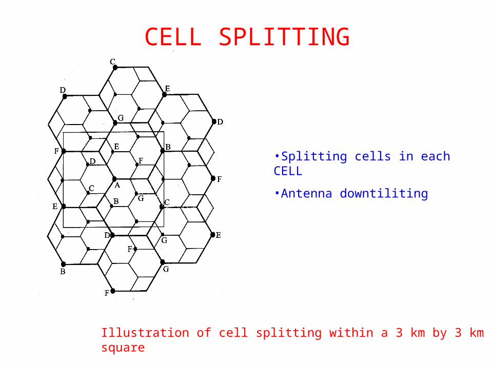
Illustration of cell splitting within a 3 km by 3 km square
CELL SPLITTING
•Splitting cells in each CELL
•Antenna downtiliting
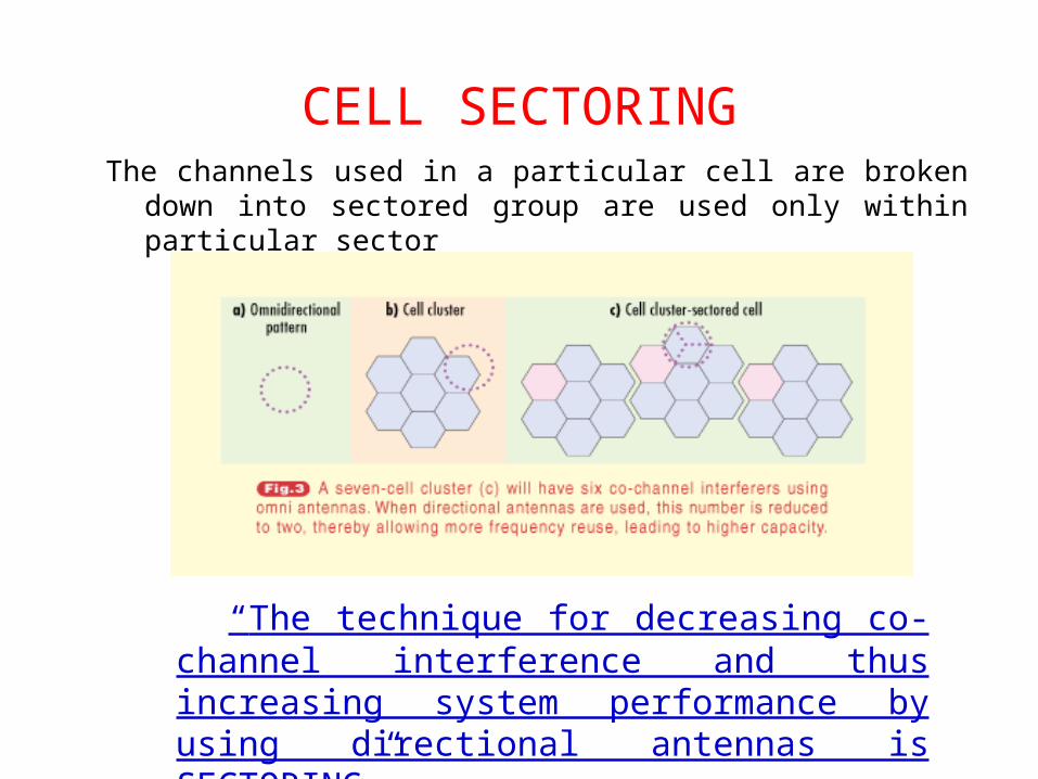
CELL SECTORINGThe channels used in a particular cell are broken down into sectored
group are used only within particular sector
“The technique for decreasing co-channel interference and thus increasing system performance by using directional antennas is SECTORING”
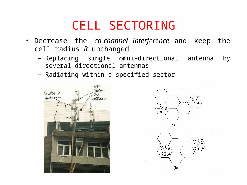
CELL SECTORING• Decrease the co-channel interference and keep the cell radius R
unchanged– Replacing single omni-directional antenna by several directional antennas
– Radiating within a specified sector
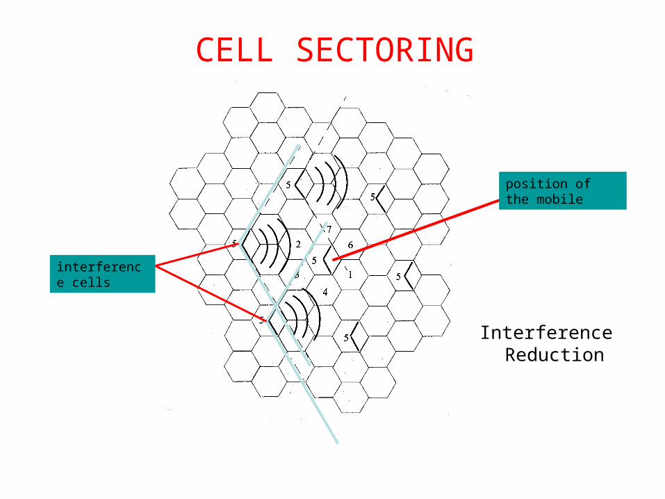
Interference Reduction
position of the mobile
interference cells
CELL SECTORING
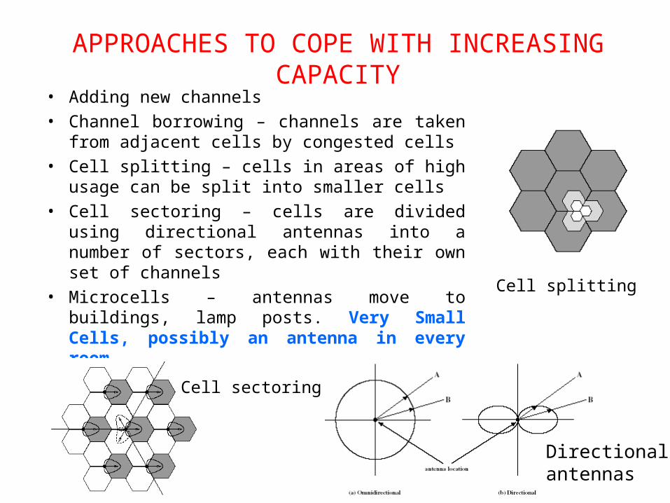
APPROACHES TO COPE WITH INCREASING CAPACITY
• Adding new channels
• Channel borrowing – channels are taken from adjacent cells by congested cells
• Cell splitting – cells in areas of high usage can be split into smaller cells
• Cell sectoring – cells are divided using directional antennas into a number of sectors, each with their own set of channels
• Microcells – antennas move to buildings, lamp posts. Very Small Cells, possibly an antenna in every room
Cell splitting
Directionalantennas
Cell sectoring
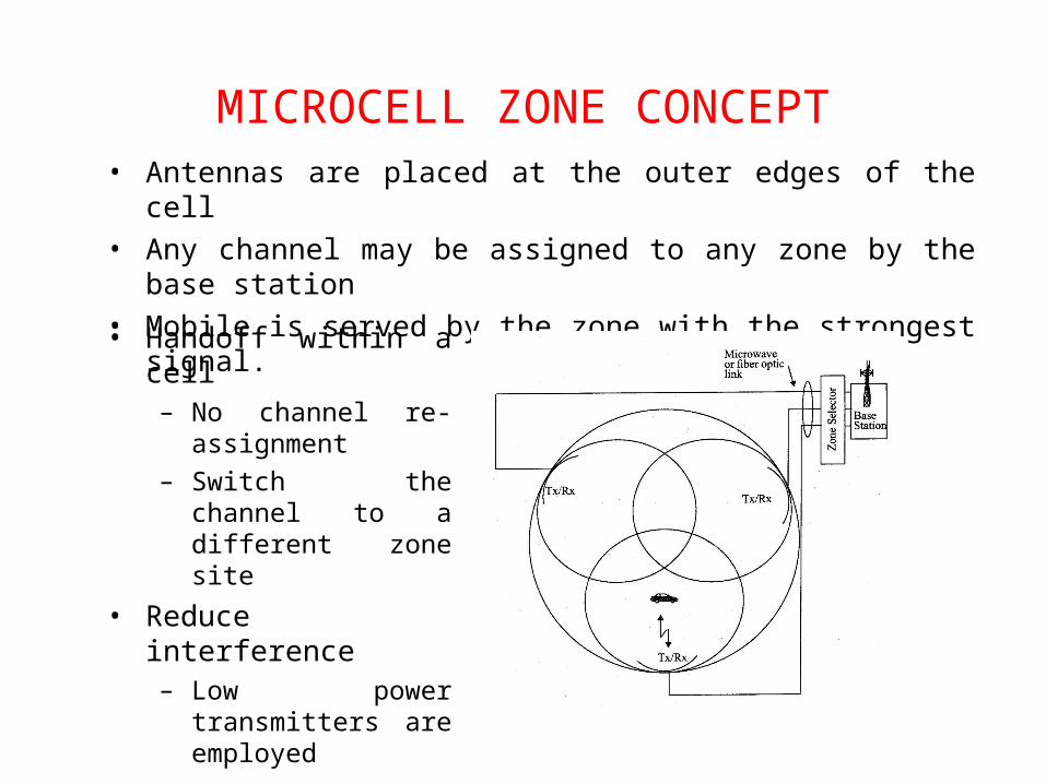
MICROCELL ZONE CONCEPT• Antennas are placed at the outer edges of the cell
• Any channel may be assigned to any zone by the base station
• Mobile is served by the zone with the strongest signal.
• Handoff within a cell– No channel re-
assignment
– Switch the channel to a different zone site
• Reduce interference– Low power transmitters
are employed
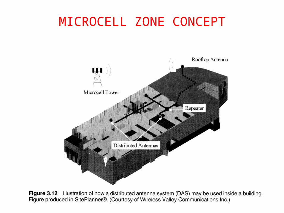
MICROCELL ZONE CONCEPT
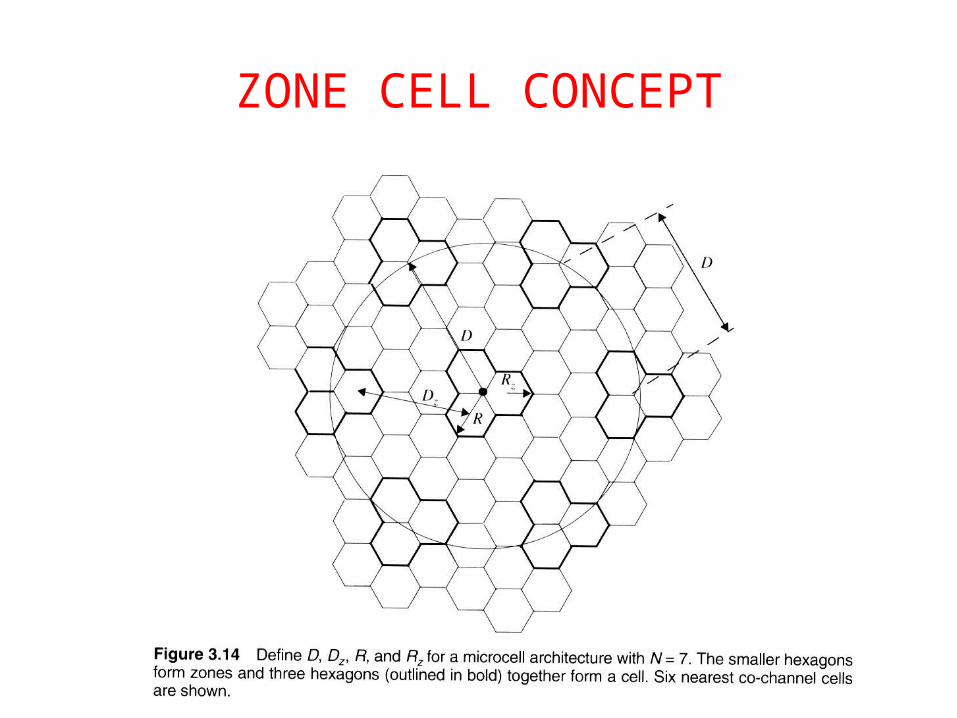
ZONE CELL CONCEPT
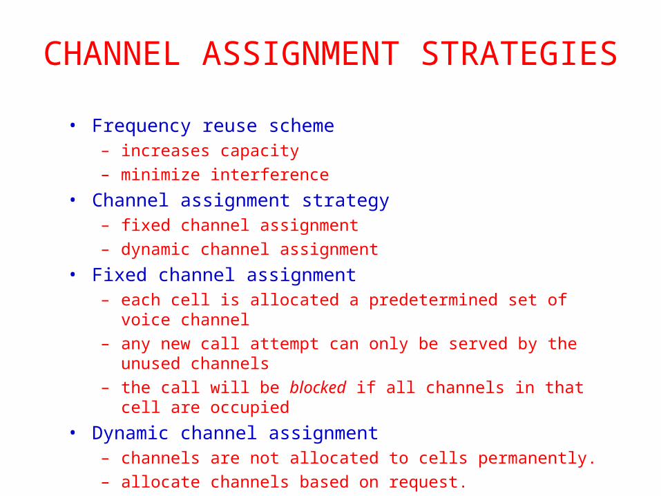
CHANNEL ASSIGNMENT STRATEGIES
• Frequency reuse scheme– increases capacity
– minimize interference
• Channel assignment strategy– fixed channel assignment
– dynamic channel assignment
• Fixed channel assignment– each cell is allocated a predetermined set of voice channel
– any new call attempt can only be served by the unused channels
– the call will be blocked if all channels in that cell are occupied
• Dynamic channel assignment– channels are not allocated to cells permanently.
– allocate channels based on request.
– reduce the likelihood of blocking, increase capacity.
CHANNEL ALLOCATION
• Channel allocation schemes can be divided in general into– Fixed Channel Allocation schemes (FCA schemes);
– Dynamic Channel Allocation schemes (DCA schemes);
– Hybrid Channel Allocation schemes (HCA schemes: combining both FCA and DCA techniques);
“A given radio spectrum is to be divided into a set of disjointed channels that can be used simultaneously while minimizing interference in adjacent channel by allocating channels appropriately (especially for traffic channels)”
FIXED CHANNEL ALLOCATION (FCA)
• In FCA schemes, a set of channels is permanently allocated to each cell in the network.
• Due to short term fluctuations in the traffic, FCA schemes are often not able to maintain high quality of service and capacity attainable with static traffic demands.
• One approach to address this problem is to borrow free channels from neighboring cells.
SIMPLE BORROWING (CB) SCHEMES
• In CB schemes, cell (acceptor cell) that has used all its nominal channels can borrow free channels from its neighboring cell (donor cell) to accommodate new calls.
• Borrowing can be done from an adjacent cell which has largest number of free channels (borrowing from the richest)
ALGORITHM• Select the first free channel found for borrowing using a
search algorithm (borrow first available scheme)• Return the borrowed channel when channel becomes free in
the cell (basic algorithm with reassignment)• To be available for borrowing, the channel must not
interfere with existing calls, as shown in the next figure.
29
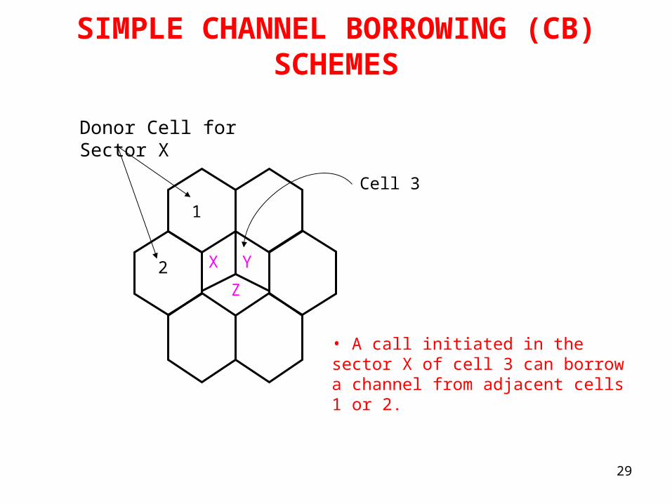
SIMPLE CHANNEL BORROWING (CB) SCHEMES
X
Z
Y2
1
Cell 3
Donor Cell for Sector X
• A call initiated in the sector X of cell 3 can borrow a channel from adjacent cells 1 or 2.
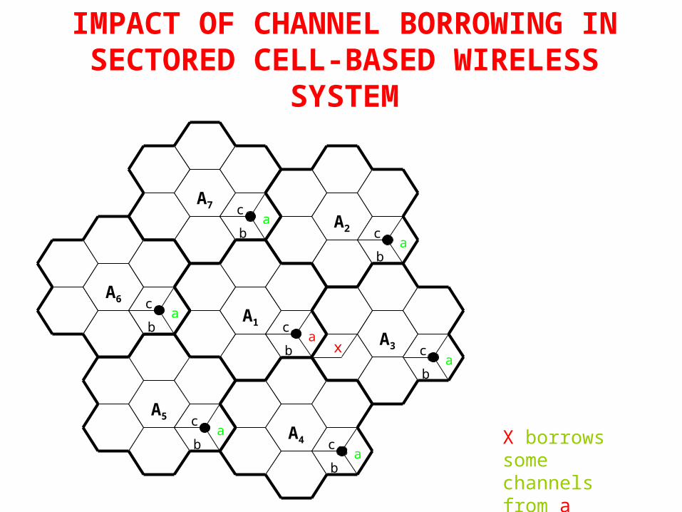
IMPACT OF CHANNEL BORROWING IN SECTORED CELL-BASED WIRELESS
SYSTEM
A7
A2
A1
A3
A4
A5
A6
c
c
c
c
c
c
c
a
a
a
a
a
a
a
b
b
b
b
b
b
b x
X borrows some channels from a
Dynamic Channel Allocation (DCA)
• In DCA schemes, all channels are kept in a central pool and are assigned dynamically to new calls as they arrive in the system.
• After each call is completed, the channel is returned to the central pool.
• It is fairly straightforward to select the most appropriate channel for any call based simply on current allocation and current traffic, with the aim of minimizing the interference.
• DCA scheme can overcome the problem of FCA scheme. However, variations in DCA schemes center around the different cost functions used for selecting one of the candidate channels for assignment.
DYNAMIC CHANNEL ALLOCATION (DCA)
• DCA schemes can be centralized or distributed. • The centralized DCA scheme involves a single controller
selecting a channel for each cell; • The distributed DCA scheme involves a number of
controllers scattered across the network (MSCs).• Centralized DCA schemes can theoretically provide the
best performance. However, the enormous amount of computation and communication among BSs leads to excessive system latencies and renders centralized DCA schemes impractical. Nevertheless, centralized DCA schemes often provide a useful benchmark to compare practical decentralized DCA schemes.
CENTRALIZED DCA
• For a new call, a free channel from the central pool is selected that would maximize the number of members in its co-channel set.
• Minimize the mean square of distance between cells using the same channel.
POWER MANAGEMENT
• Power control
• Power saving schemes
• Discontinuous transmission
• Sleep modes
• Energy efficient design
WIRELESS SECURITY
• Wireless network security requirements
• Network security requirements
• Network security
THANK YOU
END OF CHAPTER 2
Related Documents