Abstract—Since nation-wide coverage can’t immediately be achieved with the recent roll-out of UMTS networks in many countries, network performance and service continuity is highly based on co-using the existing GSM infrastructure. Therefore, seamless inter-working between the two networks is substantial for a successful launch of UMTS services. This article provides a detailed introduction into the mechanisms of cross network measurements and handovers. Based on life network experiences, a novel parameterization method for UMTS compressed mode operation and inter-system handovers is proposed and evaluated by means of dynamic event-driven simulation. Index Terms—Inter-System Handover, Inter-RAT Handover, UMTS-GSM Handover, UMTS, GSM, Compressed Mode I. INTRODUCTION HE handover algorithm generally supports the users' mobility across cells and tries to keep the user best connected either within the same network or even across heterogeneous systems, e.g. between different Radio Access Technologies (RAT). Currently, the Universal Mobile Telecommunications System (UMTS) based on Wideband Code Division Multiple Access (WCDMA) is emerging worldwide as the most promising 3 rd Generation (3G) network. The infrastructure of UMTS is closely related to the 2 nd Generation (2G) Global System for Mobile communications (GSM) which is available in more than 170 countries and provides more than 90% area coverage in lots of them. Hence, the existing GSM networks provide almost ubiquitous network accessibility allowing the GSM network to be used to give fallback coverage for WCDMA technology [1], [2]. In order to ensure seamless coverage and simultaneously maintain an overall good performance of the network, radio conditions of both networks have to be measured using compressed mode techniques [3], [4]. Triggering criteria for compressed mode and inter-system handovers have to be parameterized very accurately. On the one hand the User Equipment (UE) has to enter compressed mode and perform a handover early enough to prevent the connection from being dropped, on the other hand compressed mode causes a performance degradation on network level which have to be kept minimal and on a level being considered acceptable [5]. Usually the triggering of these events is handled by a set of threshold values for the Received Signal Code Power (RSCP) or Ec/Io of the serving cell’s Common Pilot Channel (CPICH), favorably a combination of both [6], applied to all UTRAN cells in equal measure. The proposal of this paper is to classify different types of cells depending on their individual coverage and neighboring relationship. Thus, it is possible to prevent UEs from unnecessarily entering compressed mode or even performing an inter-system handover in areas with actually sufficient UMTS coverage, i.e. the densely deployed centers of isolated UMTS clusters, but still enabling the UEs for compressed mode and inter-system handovers at the border of these UMTS clusters. The algorithm for this classification is based on the Complementary Cumulative Distributions Function (CCDF) of each individual cell’s best server RSCP and can easily be derived from field strength prediction and network planning tools. Moreover, it is adapted to all kinds of network topologies, so that no additional measurements are needed. Although the focus is on the UMTS Frequency Division Duplex (FDD) mode, some insights into the Time Division Duplex (TDD) mode are given where reasonable. The remainder of this paper is organized as follows. The inter- system handover procedure with the necessary signaling in the radio access and core networks is described in Sec. II. Compressed mode techniques are presented in Sec. III. In Sec. IV, the parameter sets for the reporting events related to compressed mode and inter-system handover as well as the proposed identification process of radio cells for optimized performance are illustrated. Sec. V presents simulation results for verification of the methods applicability and Sec. VI finally concludes this paper. II. INTER-SYSTEM HANDOVER PROCEDURE Inter-system or Inter-RAT (IRAT) handovers are an essential part within the UMTS Terrestrial Radio Access Network (UTRAN) because at the first stage of a network roll-out no complete UMTS coverage will be achieved. Therefore, inter- working with the already deployed GSM network infrastructure is mandatory for the initial operation of UMTS [7]. However, at least two networks with several components are involved in the signaling for and execution of the actual handover. Therefore, it is quite a challenging task to perform such a system change. Cell-Specific Optimized Parameterization of Compressed Mode Operation and Inter-System Handovers in UMTS/GSM Overlay Networks I. Forkel 1,4 , M. Schmocker 2 , L. Lazin 3 , M. Becker 4 , F. Debus 4 , F. Winnewisser 1,4 1 P3 Solutions, Aachen, Germany 2 Swisscom Mobile, Bern, Switzerland 3 Ericsson Switzerland 4 Chair of Communication Networks, RWTH Aachen University, Germany T

Welcome message from author
This document is posted to help you gain knowledge. Please leave a comment to let me know what you think about it! Share it to your friends and learn new things together.
Transcript
Abstract—Since nation-wide coverage can’t immediately be achieved with the recent roll-out of UMTS networks in many countries, network performance and service continuity is highly based on co-using the existing GSM infrastructure. Therefore, seamless inter-working between the two networks is substantial for a successful launch of UMTS services. This article provides a detailed introduction into the mechanisms of cross network measurements and handovers. Based on life network experiences, a novel parameterization method for UMTS compressed mode operation and inter-system handovers is proposed and evaluated by means of dynamic event-driven simulation.
Index Terms—Inter-System Handover, Inter-RAT Handover, UMTS-GSM Handover, UMTS, GSM, Compressed Mode
I. INTRODUCTION HE handover algorithm generally supports the users' mobility across cells and tries to keep the user best
connected either within the same network or even across heterogeneous systems, e.g. between different Radio Access Technologies (RAT). Currently, the Universal Mobile Telecommunications System (UMTS) based on Wideband Code Division Multiple Access (WCDMA) is emerging worldwide as the most promising 3rd Generation (3G) network. The infrastructure of UMTS is closely related to the 2nd Generation (2G) Global System for Mobile communications (GSM) which is available in more than 170 countries and provides more than 90% area coverage in lots of them. Hence, the existing GSM networks provide almost ubiquitous network accessibility allowing the GSM network to be used to give fallback coverage for WCDMA technology [1], [2].
In order to ensure seamless coverage and simultaneously maintain an overall good performance of the network, radio conditions of both networks have to be measured using compressed mode techniques [3], [4]. Triggering criteria for compressed mode and inter-system handovers have to be parameterized very accurately. On the one hand the User Equipment (UE) has to enter compressed mode and perform a handover early enough to prevent the connection from being dropped, on the other hand compressed mode causes a performance degradation on network level which have to be kept minimal and on a level being considered acceptable [5]. Usually the triggering of these events is handled by a set of
threshold values for the Received Signal Code Power (RSCP) or Ec/Io of the serving cell’s Common Pilot Channel (CPICH), favorably a combination of both [6], applied to all UTRAN cells in equal measure.
The proposal of this paper is to classify different types of cells depending on their individual coverage and neighboring relationship. Thus, it is possible to prevent UEs from unnecessarily entering compressed mode or even performing an inter-system handover in areas with actually sufficient UMTS coverage, i.e. the densely deployed centers of isolated UMTS clusters, but still enabling the UEs for compressed mode and inter-system handovers at the border of these UMTS clusters. The algorithm for this classification is based on the Complementary Cumulative Distributions Function (CCDF) of each individual cell’s best server RSCP and can easily be derived from field strength prediction and network planning tools. Moreover, it is adapted to all kinds of network topologies, so that no additional measurements are needed.
Although the focus is on the UMTS Frequency Division Duplex (FDD) mode, some insights into the Time Division Duplex (TDD) mode are given where reasonable. The remainder of this paper is organized as follows. The inter-system handover procedure with the necessary signaling in the radio access and core networks is described in Sec. II. Compressed mode techniques are presented in Sec. III. In Sec. IV, the parameter sets for the reporting events related to compressed mode and inter-system handover as well as the proposed identification process of radio cells for optimized performance are illustrated. Sec. V presents simulation results for verification of the methods applicability and Sec. VI finally concludes this paper.
II. INTER-SYSTEM HANDOVER PROCEDURE Inter-system or Inter-RAT (IRAT) handovers are an essential part within the UMTS Terrestrial Radio Access Network (UTRAN) because at the first stage of a network roll-out no complete UMTS coverage will be achieved. Therefore, inter-working with the already deployed GSM network infrastructure is mandatory for the initial operation of UMTS [7]. However, at least two networks with several components are involved in the signaling for and execution of the actual handover. Therefore, it is quite a challenging task to perform such a system change.
Cell-Specific Optimized Parameterization of Compressed Mode Operation and Inter-System Handovers in UMTS/GSM Overlay Networks
I. Forkel1,4, M. Schmocker2, L. Lazin3, M. Becker4, F. Debus4, F. Winnewisser1,4 1 P3 Solutions, Aachen, Germany
2 Swisscom Mobile, Bern, Switzerland 3 Ericsson Switzerland
4 Chair of Communication Networks, RWTH Aachen University, Germany
T

Fig. 1 exemplarily shows how the inter-system handover is performed from UTRAN to the Base Station Subsystem (BSS) of GSM including signaling between a UMTS Core Network (CN) and a 2G Mobile Switching Centre (MSC) according to [8].
The inter-system handover is initiated upon detection of a trigger from the Radio Resource Control (RRC) protocol based on the reception of User Equipment (UE) measurement reports. The serving Radio Network Controller (RNC) sends the Radio Network Application Part (RANAP) message “Relocation Required” to the CN (1).
The UMTS CN will forward this request to the GSM MSC (indicated in the received message) over the Mobile Application Part (MAP)/E interface using the MAP message “Prepare Handover” (2). The MAP/E interface is initially designed to connect MSCs in a GSM network but can be re-used for inter-system handover signaling as well.
“Handover Request” and “Handover Request Acknowledgment” in steps (3) and (4) follow the regular GSM procedures and are shown only for clarity. Once initial procedures are complete in GSM MSC/BSS the MSC returns MAP/E message “Prepare Handover Response” (5).
CN responds to the initial request from the serving RNC by responding to the RNC with RANAP message “Relocation Command” (6).
Via existing RRC connection the serving RNC sends an RRC message “Handover from UTRAN” to the UE (7). One or several messages from the other system can be included in this message. Procedures related to synchronization etc. to GSM BSS are not shown. Steps (8), (9) and (10) follow regular GSM procedures and are shown only for clarity.
Upon detection of the UE within the GSM network the MSC sends the MAP/E message “Send End Signal Request” to the CN (11).
The CN initiates release of resources allocated by the former SRNC with the “Iu Release Command” (12).
Previously allocated bearer resources are released within UMTS, e.g. using RANAP and ALCAP [ALCAP not shown]. This procedure is terminated with the “Iu Release Complete” message (13).
Procedure is concluded from UMTS point of view by CN sending the MAP/E message “Send End Signal Response” which is not sent until the end of the call (14).
The complete procedure is transparent to the UE except for measurement reporting and radio bearer reconfiguration when
switching from UMTS to GSM operation. Notwithstanding, accurate measurements are mandatory for proper handover performance giving Ec/Io a favorable role compared to RSCP measurements thanks to the low tolerance [7], [9]. Further details on measurement reporting and triggering conditions can be found in [6], [10], [11].
III. COMPRESSED MODE OPERATION Transmission and reception is normally continuous in FDD operation. In order to gather measurements on different frequencies than the actually allocated carrier, the UE must be given either idle times or a second transceiver to switch to other frequencies. Since an additional receiver is cost extensive and hard to implement, the introduction of a slotted mode operation seems to be favorable [12]. This kind of operation in UTRA is called compressed mode.
Therefore, inter frequency and IRAT handover measurements on different carrier frequencies are performed in compressed mode in UTRA-FDD or during idle slots in UTRA-TDD. In [13], additional insight to compressed mode techniques and their performance is given.
The overall IRAT handover procedure is then based on a simple three state model with the states “UMTS regular mode”, “UMTS compressed mode” and “Drift system (GSM)”' as illustrated in Fig. 2. State transitions are possible in both directions between regular mode and compressed mode, from compressed mode to the drift system, and from the drift system back to the regular mode in UMTS. It is not possible to handover to a different system without measuring it, so there is not direct transition from the regular mode to the drift system. The transition is initiated by the inter-system
Fig. 1. Message sequence chart for inter-system (UTRAN to GSM) handover, call control signalling not shown.
handover algorithm and may be based on the Ec/Io of the CPICH, the RSCP, or a combination of both [6]. In addition, internal timers are included in order to prevent the system from instabilities due to vastly varying measurement values. A state transition is only performed if the condition is fulfilled for at least the period of the corresponding timer.
Three methods for compressed mode are proposed in the UMTS standard [14]: • Puncturing: One way to save transmission time is to
remove information by puncturing; this is especially applicable in combinations of transport channels and physical channels where the rate matching is done by repetition, i.e. 12.2 kbps speech in UTRA-FDD [15].
• Spreading Factor Reduction: By dividing the spreading factor by two, twice the data will be transmitted in the same amount of time, as the data rate is twice as high. On the one hand spreading factor reduction in the FDD mode will only be possible if the actual spreading factor is larger than 4, because 4 is the minimal allowed spreading factor. On the other hand, enough transmission power has to be available for the compressed mode period. The reason is that a lower spreading factor requires higher Signal to Interference Ratio (SIR) to provide equal robustness against transmission errors. The Orthogonal Variable Spreading Factor (OVSF) codes used for compressed mode are ⎣ ⎦( )2
2/SFCMn/cc = , where
(n)cSF is the OVSF code of the non-compressed frame, as
described in [16], and ⎣ ⎦⋅ means the closest integer smaller than the argument.
• Higher Layer Scheduling: The higher layers are scheduling their data for a later transmission, using subsets of the allowed Transport Format Combination (TFC).
There are two methods possible regarding the frame structure resulting out of compressed mode operation, single-frame and double-frame [14]. The first method implements the transmission gap within one radio frame of 10 ms length, the latter implements the transmission gap on the border between two consecutive radio frames as depicted in Fig. 3.
The position of the transmission gap in one single radio frame can be at the start of, within, or at the end of a radio frame. For the double frame method, the transmission gap can be asymmetric or symmetric according to the border of the
two radio frames. As the time requirements for the measurements vary widely
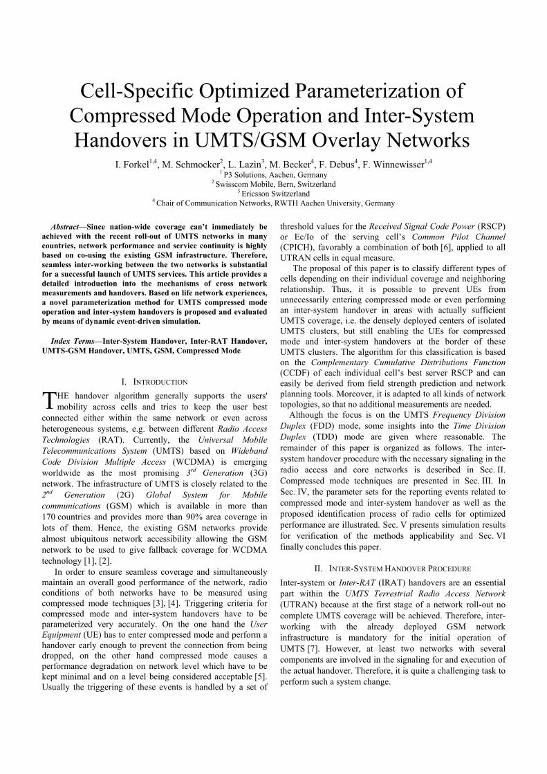
there are different compressed mode patterns defined as illustrated in Fig. 4. The parameters that characterize a transmission gap pattern are: • TGSN: The Transmssion Gap Starting slot Number
(TGSN) is the slot number of the first transmission gap slot in the first radio frame of the transmission gap pattern.
• TGL: The Transmission Gap Length (TGL) is the length of the transmission gap in slots.
• TGD: If there are two transmission gaps in one pattern, the Transmission Gap Duration (TGD) will be the duration between the starting slots of the two transmission gaps.
• TGPL: The Transmission Gap Pattern Length (TGPL) is the duration of transmission gap pattern expressed in radio frames.
To allow different measurements to take place alternately, different sequences of patterns are defined, which are characterized by the following parameters: • TGPRC: The Transmission Gap Pattern Repetition
Count (TGPRC) gives the connection frame number of
Fig. 4. Compressed mode operation. The example shows a sequence of two transmission gap patterns with two transmission gaps each.
Fig. 2. Inter-system handover and compressed mode state model. Note that the handover back to UMTS leads to the regular operation instead of compressed mode.
Fig. 3. Possible transmission gap positions; upper plot: single-frame method, lower plot: double-frame method.
TABLE I TRANSMISSION GAP PARAMETERS FOR SPECIFIC MEASUREMENTS
Measurement TGSN [slot number]
TGL1 [slots]
TGPL1 [frames]
UTRA-FDD Inter-Frequency 4 7 3 UTRA-TDD Inter-Frequency 10 10 11 GSM Carrier RSSI 4 7 12 GSM BSIC 4 7 8

the first pattern within the sequence. • TGCFN: The number of patterns within the sequence is
defined by the Transmission Gap Connection Frame Number (TGCFN).
Exemplary parameters are depicted in Fig. 4 and have to be of integer value, cf. [16]
Single compressed mode patterns for reference and testing are given in Table I for different measurement reasons. Spreading factor reduction is the appropriate compressed mode mechanism for almost all measurements except for the UTRA-TDD downlink [17]. No multiple compressed mode patterns and no patterns with more than one transmission gap are recommended at the moment. More general sets of transmission gap parameters and the length of measurement periods are given in [18], [19].
During compressed mode more power is used outside the transmission gap and no power at all is used in the transmission gap. Furthermore, the Transmit Power Control (TPC) command may not be transmitted during the gaps. Therefore, UMTS power control has to be modified in case of compressed mode operation as described in [20]. The aim is to recover the desired SIR as fast as possible after the transmission gap. Therefore, larger TPC steps might be defined for a restricted period after the transmission gap.
IV. OPTIMIZATION OF THE INTER-SYSTEM HANDOVER In order to reduce the compressed mode overhead and avoid unnecessary and unwanted handovers, different types of cells depending on their neighboring relationships should be distinguished for the optimization of the inter-system handover algorithm. In UMTS cells with restricted coverage area and nearby neighbors, compressed mode operation should be prevented. Cells with sufficient UMTS neighborhood but larger coverage area should at least be prepared for inter-system handover to react to fading radio conditions or increasing interference and use GSM as a fall-back system. Finally, border cells of UMTS should timely switch to GSM before the connection drops out due to missing coverage and soft handover ability. The challenging task is the identification of these types of UMTS cells.
The triggering of compressed mode and IRAT handover is handled by a set of threshold values and timers [2]. These values are parameterized very carefully to find a compromise of the overall network performance and initiating compressed mode and inter-system handover in time [2]. With carefully defined sets of threshold values it is possible to distinguish different types of cells with respect to their individual coverage conditions and reduce compressed mode overhead and unwanted handovers, but still preserve the capability of handovers where they are necessary.
Without loss of generality, we assume three different types of UMTS cells in this paper:
• Inner cells: The best server coverage area of these cells is restricted and they have nearby neighbors. Within their range compressed mode operation should be prevented, except for e.g. capacity reasons.
• Transit cells: These cells do have a sufficient UMTS neighborhood but a larger coverage area as well. Thus, associated UEs should at least be prepared for inter-system handovers to react to increasing interference and use GSM as a fall-back system.
• Outer/border cells: Due to their location at the edge of UMTS coverage, they should be well prepared for inter-system handovers and switch to GSM timely before the connection drops out.
A simple but well appropriate classification of the cells is based on the Complementary Cumulative Distribution Function (CCDF) of the best server RSCP. The RSCP measure is chosen because it gives the better indication of coverage [7]. The CCDF returns the percentage how often a (random) variable or measurement quantity is above a certain level. The according statistical equation is Fc(x) = P(X > x) = 1 - F(x), with F(x) being the Cumulative Distribution Function (CDF). Applied to the classification problem, a CCDF of the best server area of a specific cell returns the percentage of the area wherein the RSCP of the CPICH is above an arbitrary level. The best server area of a specific cell is the area wherein it is the “loudest” transmitter concerning the RSCP. The concrete application of the CCDF will be as follows.
Fig. 5 shows sketches of the above mentioned cell types and their corresponding CCDFs. Since they are for illustration purposes only, the sketches and the CCDFs are realistic but displayed in an exemplary and simplified way. At the y-axes of the CCDFs is the percentage of the cell’s best server area, at the x-axes the RSCP level.
The left hand plot shows an inner cell with its restricted range and the nearby neighbors at all sides like it could be in a dense urban area. From the CCDF of this cell it can be seen that the RSCP level is quiet high in the complete best server area. For this example in 90% of this area the RSCP is at a level of about -76 dBm. This high RSCP level in most of the cell area and the steep decay of the CCDF are characteristic for inner cells.
A transit cell is displayed in the middle plot of Fig. 5. Its best server area is already larger but there is still UMTS neighborhood around it. Referring to this exemplary figure an inter-system handover might occur in the frayed corner of this cell, though it is much more likely that there is first a handover to one of the frayed neighbor cells before the UE moves completely out of UMTS range. This is very typical for transit cells, there is the possibility of an inter-system handover, but usually the UMTS neighborhood is sufficient enough in terms of coverage that this handover rarely occurs. The CCDF confirms this evaluation. The RSCP level is not as high as for inner cells, but still acceptable. An RSCP of -90 dBm is given in about 80% of this cell’s best server area. Characteristic for the transit cells is this fair RSCP level in most of their best server area and the continuous decay of the CCDF.
Finally, the right hand plot illustrates an exemplary border cell. Due to its location at the edge of the UMTS cluster, its best server coverage area is quiet large including far away radio signal propagation. The CCDF shows high fraction of

-120 -110 -100 -90 -80 -70 -60 -50 -40 -30RSCP [dBm]
100
90
80
70
60
50
40
30
20
10
0
CC
DF
[%]
-120 -110 -100 -90 -80 -70 -60 -50 -40 -30RSCP [dBm]
100
90
80
70
60
50
40
30
20
10
0
CC
DF
[%]
-120 -110 -100 -90 -80 -70 -60 -50 -40 -30RSCP [dBm]
100
90
80
70
60
50
40
30
20
10
0
CC
DF
[%]
-120 -110 -100 -90 -80 -70 -60 -50 -40 -30RSCP [dBm]
100
90
80
70
60
50
40
30
20
10
0
CC
DF
[%]
-120 -110 -100 -90 -80 -70 -60 -50 -40 -30RSCP [dBm]
100
90
80
70
60
50
40
30
20
10
0
CC
DF
[%]
-120 -110 -100 -90 -80 -70 -60 -50 -40 -30RSCP [dBm]
100
90
80
70
60
50
40
30
20
10
0
CC
DF
[%]
-120 -110 -100 -90 -80 -70 -60 -50 -40 -30
RSCP [dBm]
100
90
80
70
60
50
40
30
20
10
0
CC
DF
[%]
-120 -110 -100 -90 -80 -70 -60 -50 -40 -30RSCP [dBm]
100
90
80
70
60
50
40
30
20
10
0
CC
DF
[%]
-120 -110 -100 -90 -80 -70 -60 -50 -40 -30RSCP [dBm]
100
90
80
70
60
50
40
30
20
10
0
CC
DF
[%]
-120 -110 -100 -90 -80 -70 -60 -50 -40 -30RSCP [dBm]
100
90
80
70
60
50
40
30
20
10
0
CC
DF
[%]
Fig. 5. Cell identification process: the best server RSCP for an “inner” UMTS cell indicates very good coverage with 90% of the expected signal level above -75 dBm (left hand side); with a best server RSCP CCDF tailing off to some smaller values, e.g. having about 20% values below -90 dBm, “transit” cells are identified where compressed mode and inter-system handover functionality should earlier be enabled (middle); “outer” cells at the edge of coverage show the RSCP CCDF shifted to very low signal levels, necessitating an early preparation for compressed mode and inter-system handovers (right hand side)
RSCP values actually meaning uncovered UMTS areas. The steep decay is characteristically shifted to low RSCP levels. In this example not even 50% of the best server area is being covered with -100 dBm. A minimum desired level of about -103 dBm to sustain voice services is achieved for only 50% of this area. The decay shift to lower power ranges is very obvious in this figure, indicating a sector of an almost isolated site.
This classification idea and the evaluation based on the CCDF are applicable to cells, sectors and base stations in all terrains equally. Only data out of field strength prediction tools or sufficient life network measurement data are needed to calculate the CCDFs. The actual levels or percentages to use as the classification limits and whether to consider cells or sectors can be chosen arbitrarily depending on the specific network topology and requirements. Due to CCDF’s properties this algorithm can handle all kinds of terrains as well. If the specific cell was located in a dense urban area, a deep shadow would cause a fair drop in the percentage of the best server area covered with a high RSCP level due to cell’s limited size compared to a similar cell with no shadow. A cell in a suburban area on the other hand covers a much larger area, so one deep shadow would not cause a severe change in the CCDF, this cell would not be classified an inner cell anyway.
Having identified different classes of cells, appropriate parameter sets have to be chosen in order to improve the
compressed mode and inter-system handover behavior within the network. Tab. II presents three parameter sets for the usage in inner, transit and outer cells, respectively. Whereas the Set 1 parameters are causing compressed mode as well as inter-system handovers to be performed already at good radio conditions, Set 3 parameters are a lot more conservative. Thus, the UE will be kept longer and more stable within plain UMTS operation. Furthermore, the Set 2 parameters will give a compromise. With these parameters, compressed mode is turned on at a RSCP level of -100 dBm or Ec/Io of -11dB and the inter-system handover is executed at a RSCP level of -105 dBm or -14 dB. Higher thresholds are considered for turning off compressed mode and returning back to regular UMTS operation.
An appropriate classification with respect to an RSCP threshold of -90 dBm and coverage thresholds at 75% and 90% in order to identify inner, transit and outer cells in a real network scenario is illustrated in Fig. 6. For “inner” UMTS cells, the cell area covered with an RSCP above -90 dBm should at least be 90%. For these cells, the compressed mode and inter-system handover functionality is almost disabled by Set 3 parameters. In the “transit” cells, where at least 75% of the cell area is covered by an RSCP above -90 dBm,
Fig. 6. Classification of UMTS cells for different compressed mode and inter-system handover parameterization.
TABLE II INTER-SYSTEM HANDOVER PARAMETERS IN DIFFERENT CONFIGURATIONS
Parameter Set 1 Set 2 Set 3
Turn-off compressed mode Maximum RSCP [dBm] -85 -95 -105 Maximum Ec/Io [dB] -8 -9 -10 Time to trigger [ms] 320 320 320 Turn-on compressed mode Minimum RSCP [dBm] -90 -100 -110 Minimum Ec/Io [dB] -10 -11 -12 Time to trigger [ms] 320 320 320 Turn-on compressed mode Minimum RSCP [dBm] -95 -105 -115 Minimum Ec/Io [dB] -13 -14 -15 Time to trigger [ms] 100 100 100

parameter Set 2 applies. Remaining cells with significant proportional areas covered by lower RSCP levels are parameterized by Set 1.
V. SIMULATION RESULTS In order to evaluate the proposed algorithm, the event-driven dynamic system-level Generic Object-Oriented Simulation Environment (GOOSE) is used. This tool has been developed at the Chair of Communication Networks at RWTH Aachen University. It has been extensively used to determine the performance of network algorithms for GSM/GPRS, UMTS and cdma2000 systems [2], [11].
The inter-system handover is evaluated in a scenario covering the area around the city of Biel, Switzerland including omni-present GSM coverage and an embedded UMTS covered part with 44 Node B. Simulation assumptions are based on [21] concerning service and radio propagation modeling. 40 active voice connections per UMTS sector are generated simultaneously to create a high system load and a reasonable interference floor. To maintain a stable service a conservative Carrier to Interference Ratio (CIR) of -18 dB is assumed. The user’s mobility is randomly modeled with an average speed of 30 km/h in order to derive an impression over the whole scenario area instead of only few locations on existing roads (although a real network would face the inter-system handover most probable at restricted locations).
For the results in this section, the locations of individual inter-system related handover events are of interest. Therefore, in the following figures yellow dots mark the locations where compressed mode is switched on. In compressed mode, the UE leaves a yellow track in the map. Note that the lines do not necessarily correspond to the actual
movement of the mobile. Green dots illustrate locations where compressed mode is switched off and the mobile returns to regular UMTS operation. Red dots mark the locations where an inter-system handover, i.e. the handover from UMTS to the GSM network takes place. Mobiles, which switched to GSM, leave a red track in the map. Again, these tracks do not correspond to the route taken by the mobile. Finally, blue dots mark locations where the mobiles return from GSM to regular UMTS mode.
The results for the inter-system handover simulations in Biel rely on the three sets of combined Ec/Io and RSCP criteria as given in Tab. II. Fig. 7 illustrates the locations where compressed mode is switched on or off, and where inter-system handovers took place for parameter Set 1. The background map considers the average CPICH reception level per pixel with respect to Set 1 thresholds. In the yellow area with an RSCP below the threshold for switching on compressed mode mobiles are expected to turn to compressed mode operation. When moving towards the UMTS Node B and into the green area, compressed mode is switched off again. Moving further out of the UMTS coverage area, the UE finally handovers to the GSM network in the red area where
Fig. 7. Locations of compressed mode and inter-system handover events using only parameter Set 1. Underlying is the illustration of averaged RSCP regions based on Set 1 thresholds.
TABLE III RESULTS FOR DIFFERENT INTER-SYSTEM HANDOVER PARAMETER SETS
Parameter set combination
Set 1 (all 44)
Set 2 (inner 10)
Set 1 (others)
Set 3 (inner 10)
Set 1 (others)
Set 3 (inner 10)
Set 2 (transit 10)
Set 1 (others)
Time in UMTS 95.27% 95.10% 95.58% 95.47% Compressed mode 09.36% 08.30% 08.30% 07.50% Time in GSM 04.73% 04.90% 04.42% 04.53%
Fig. 8. Locations of compressed mode and inter-system handover events using a combination of parameter Set 1 to Set 3 based on RSCP CCDF. 10 inner cells using Set 3, 10 transit cells using Set 2, others using Set 1.

the RSCP is below the threshold for switching to GSM. It can be seen that most events fit to their corresponding region. Nevertheless, some inter-system handovers appear in the city center and also several compressed mode events accumulate within certain areas where UMTS actually should provide sufficient coverage.
When applying the mixed configuration as proposed in Sec. IV, Fig. 8 shows the resulting system behavior. The areas marked by the inner and outer polygons represent the cell areas as identified by the RSCP CCDF evaluation for “inner” and “transit” cells, respectively. We can clearly see this identification process as a sophisticated approach in order to distinguish different cell categories.
As expected, unwanted and unnecessary compressed mode operation and inter-system handovers have been removed from the inner cells’ area and significantly reduced in the transit cells’ area. In addition, the operating state probabilities are collected in Tab. III. We can see that the combination of all parameter sets individually assigned to the different cell categories reduces the compressed mode operation from 9.4% to 7.5%, i.e. by 20%, without affecting the necessary handovers to GSM at the scenario border. Hence, while maintaining the same overall quality of service in terms of continuous service delivery, the signaling and interference overhead has been significantly reduced.
VI. CONCLUSION In this paper, we discussed the technical challenges of introducing the inter-system handover into a UMTS/GSM overlay network. We proposed an easy but very sophisticated method to derive well suitable threshold and trigger parameters with respect to the actual network topology and coverage situation. The main advantage is the inherent identification of different category cells by their individual best server RSCP distribution which can either be based on life network measurements or field strength prediction from radio planning tools.
With the proposed method it is possible to reduce the compressed mode overhead by 20% still maintaining suitable GSM fall-back functionality. The approach allows to pre-configure the network based on radio network planning data and to avoid compressed mode overhead as well as unwanted inter-system handovers in the life network.
In principle, this approach has been introduced into the Swisscom UMTS network and proven applicable. However, further fine-tuning might be necessary. The differentiation into three categories can of course be replaced by continuously varying threshold settings depending on the level of coverage. Moreover the actual thresholds for cell categorization and parameter values are subject to vary in order to reflect operator specific quality targets in the network. Thus, the proposal leaves some freedom to the network engineers in the field to find even further optimized parameter sets within their local area.
ACKNOWLEDGMENT The authors like to thank Prof. B. Walke of ComNets, P. Weibel from Swisscom Mobile and P. Seidenberg from P3 Solutions for their support of this work. The fruitful co-operation with Swisscom Mobile throughout the project is highly appreciated. We would also like to thank the anonymous reviewers for their valuable feedback.
REFERENCES [1] G. Alsenmyr, J. Bergström, M. Hagberg, A. Milén, W. Müller, H. Palm,
H. v.d.Velde, P. Wallentin, F. Wallgren, “Handover between WCDMA and GSM”. Ericsson Reviev No. 1, 2003
[2] I. Forkel, “Performance Evaluation of the UMTS Terrestrial Radio Access Modes”. PhD thesis, Chair of Communication Networks, RWTH Aachen University, Wissenschaftsverlag Mainz, 2005
[3] S. Hämäläinen, T. Henttonen, J. Numminen, J. Vikstedt, “Network Effects of WCDMA Compressed Mode“. 57th IEEE Vehicular Technology Conference (VTC), pp. 881-885 Vol. 2, April 2003.
[4] D. Lugara, L. Ammi, M. Griguer, J. Tartière, “UMTS to GSM Handover Based on Compressed Mode Technique”. IEEE International Conference on Communications (ICC), pp. 3051-3055, Vol. 5, June 2004.
[5] C. Chang, C. Huang, “Capacity-Based Compressed Mode for Inter-System Handover in UMTS”. IEEE Wireless Communications and Networking Conference, (WCNC), pp. 1250-1254, April 2006.
[6] Z. Zhang, “WCDMA Compressed Mode Triggering Method for IRAT Handover”. IEEE Wireless Communications and Networking Conference (WCNC), pp. 849-853 Vol. 2, March 2004.
[7] M. Benson, H.J. Thomas, “Investigation of the UMTS to GSM Handover Procedure”. 55th IEEE Vehicular Technology Conference (VTC), pp. 1829-1833, Vol. 4, May 2002.
[8] 3GPP, TS 25 931 V 5.1.0, UTRAN Functions, Examples on Signaling Procedures. June 2002.
[9] E. Jugl, U. Bernhard, H. Pampel, “Strategy and Performance of UMTS-GSM Handover”. 4th International Conference on 3G Mobile Communications Technologies, pp. 217-221, June 2003.
[10] D. Lugara, J. Tartière, L. Girard, “Performance of UMTS to GSM Handover Algorithms”. 15th IEEE International Symposium on Personal, Indoor and Mobile Radio Communications (PIMRC), pp. 444-448, Vol. 1, September 2004.
[11] I. Forkel, M. Schinnenburg, B. Wouters: “Performance Evaluation of Soft Handover in a Realistic UMTS Network”. 57th IEEE Vehicular Technology Conference (VTC), April 2003
[12] A. Toskala, O.A. Lehtinen, and P. Kinnunen, “UTRA GSM Handover from Physical Layer Perspective.” ACTS Mobile and Communications Summit, Sorento, Italy, 1999.
[13] M. Gustafsson, K. Jamal, and E. Dahlmann., “Compressed Mode Techniques for Inter-Frequency Measurements in a Wideband DS-CDMA Systems.” IEEE International Symposium on Personal, Indoor and Mobile Radio Communications (PIMRC), pp. 231-235, Helsinki, Finland, Sep. 1997.
[14] 3GPP, TS 25 212 V 4.0.0, Multiplexing and Channel Coding (FDD). Mar. 2001.
[15] 3GPP, TS 25 104 V 4.0.0, UTRA (BS) FDD Radio Transmission and Reception. Mar. 2001.
[16] 3GPP, TS 25 215 V 4.1.0, Physical Layer - Measurements (FDD). Mar. 2001.
[17] 3GPP, TR 34 108 V 4.5.0, Common Test Environments for User Equipment (UE) Conformance Testing. Dec. 2002
[18] 3GPP, TS 25 133 V 4.6.0, Requirements for Support of Radio Resource Management (FDD). Dec. 2002.
[19] 3GPP, TR 25 922 V 5.0.0, Radio Resource Management Strategies. Mar. 2002.
[20] 3GPP, TS 25 214 V 4.0.0, Physical Layer Procedures (FDD). Mar. 2001. [21] ETSI, “TR 101 112, Selection Procedures for the Choice of Radio
Transmission Technologies of the UMTS (UMTS 30.03),” European Telecommunications Standards Institute, Apr. 1998.
Related Documents