CELIKEL CHARGER V OPERTORS INSTRUCTION MANUAL

Welcome message from author
This document is posted to help you gain knowledge. Please leave a comment to let me know what you think about it! Share it to your friends and learn new things together.
Transcript

CELIKEL CHARGER V
OPERTORS INSTRUCTION
MANUAL

TABLE OF CONTENTS
INTRODUCTION ..............................................................................................................................
Using This Manual ........................................................................................................................
CERTIFICATE OF WARRANTY ............................................................................................................
Model and Serial Number Information ......................................................................................
SAFETY .............................................................................................................................................
PRODUCT TECHNICAL FEATURES .....................................................................................................
DELIVERY AND TRANSPORTATION ..................................................................................................
ATTACHING TO THE TRACTOR .........................................................................................................
ADJUSTMENT THE LENGHT OF SHAFT .............................................................................................
HYDRAULIC .......................................................................................................................................
BRAKES .............................................................................................................................................
LOADING SHOVEL (OPTIONAL) ........................................................................................................
FEED MIXTURE PREPARATION ........................................................................................................
MINERAL / PREMIX FILLING HOPPER ...............................................................................................
WEIGHING SYSTEM (Optional) ........................................................................................................
ADJUSTMENT OF STABLE KNIVE ......................................................................................................
MAINTENANCE .................................................................................................................................
LUBRICATION ...................................................................................................................................
CONVEYOR (Optional) .....................................................................................................................
POSSIBLE PROBLEMS AND SOLUTIONS ............................................................................................

Dear User;
Congratulations for purchasing a Celikel Charger V. We appreciate your business. You have
purchased one of the best built, most reliable mixers available. Please read this user's and
operational manual carefully in order to prevent any possible malfunctions and to know more
closely before use your machine. This manual contains important warnings for the perfect
functioning of your machine maintenance practices and practical in use.
We wish to use your machine in good times.
CELIKEL TARIM MAKINELERI SAN. VE TIC. LTD. ŞTI.
USING THIS MANUAL
This manual should be considered a permanent part of your machine, and should remain with
the machine if you sell it.
This manual has been designed to help you become familiar with your unit.

CERTIFICATE OF WARRANTY
Warranty conditions
1. The warranty period for the product from the date of delivery to the user 1 (one) year.
2. Except for showing deformation depending on the usage and designated as parts supplies are under
the warranty of our company.
3. The maximum time to repair the product within thirty (30) days.
4. In case of failure of the product, repairing time will be added to the warranty period
5. The warranty period of product one to one replacement is up to the remaining warranty period of
the purchased product.
6. Every maintenance except for will made authorized and user would be out of warranty
7. Depending on the intensity of use of the product (knife, rubber bands, etc.) can not be replaced
under warranty parts.
8. Not manufactured by Çelikel products warranty period of the components and systems supplied as
finished is limited to the conditions specified by the supplier.
9. Supplied with the propeller such as the middle arm and shaft as a gift, it is out of warranty parts.
10. Service stations do not fall under warranty repair of transportation, packaging, parts and service
expenses are paid by the customer.
11. Users can not demand the approval of the guarantee in case of changes on the machine or original
spare parts if not used by Çelikel.
12. Use the machine unpropert and uncorrectly would not be under of the warranty.
13. Manufacturer is not responsible for maintenance which must is made by customer.
14. Unapproved and not signed by the customer documents are invalid in warranty.

15. Responsible is belong to dealers, agents or representatives of the manufacturer for filling in the
warranty document.
16. Purchased products are out of warranty in all kinds of changes to the warranty certificate.
Çelikel Tarım Makineleri San. ve Tic. Ltd. Şti
3. OSB İhsan Dede Cad. 13. Sok. No:10
Selçuklu / KONYA/ TÜRKİYE
+90 444 49 42
Product Name : CHARGER V………
Model of Machine :
Serial Number :
Delivery Time :
Production Year :
Seller Company / Authorized Service
Stamp :
Sign :

MODEL AND SERIAL NUMBER INFORMATION
The serial number tag is located on the front lower panel.
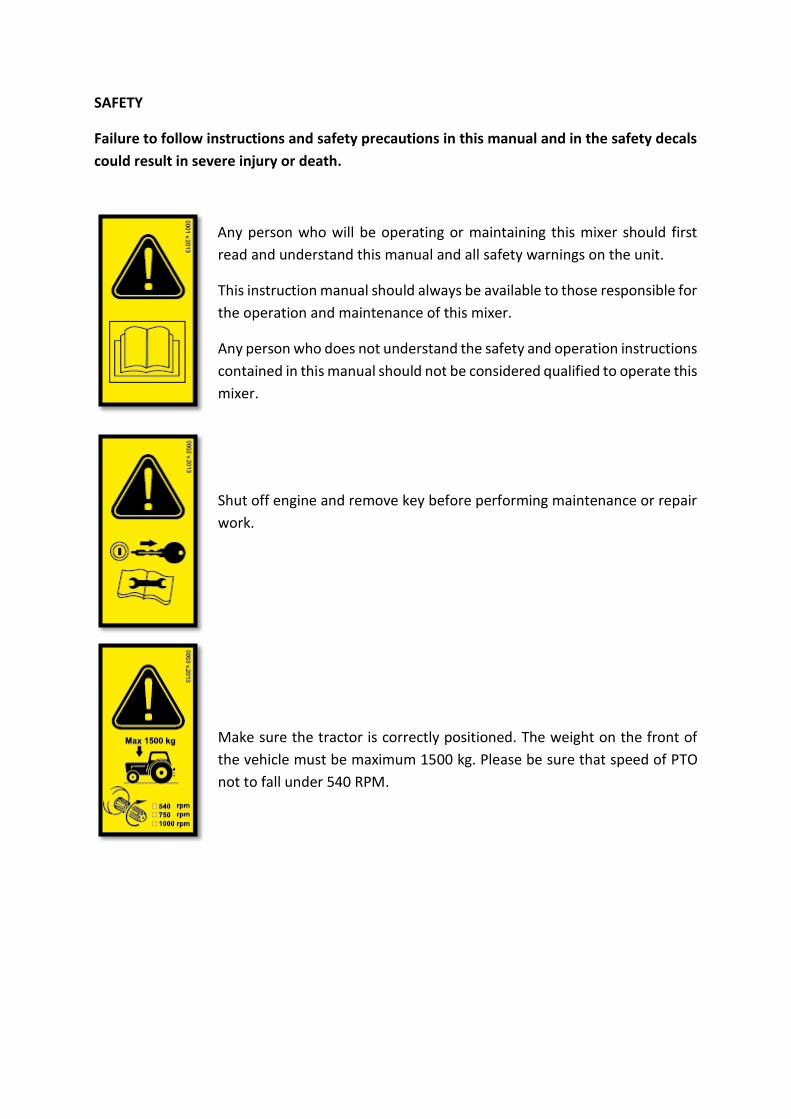
SAFETY
Failure to follow instructions and safety precautions in this manual and in the safety decals
could result in severe injury or death.
Any person who will be operating or maintaining this mixer should first
read and understand this manual and all safety warnings on the unit.
This instruction manual should always be available to those responsible for
the operation and maintenance of this mixer.
Any person who does not understand the safety and operation instructions
contained in this manual should not be considered qualified to operate this
mixer.
Shut off engine and remove key before performing maintenance or repair
work.
Make sure the tractor is correctly positioned. The weight on the front of
the vehicle must be maximum 1500 kg. Please be sure that speed of PTO
not to fall under 540 RPM.

Always fire extinguisher should be kept on the tractor.
The tractor must always be taken first aid kit.
Keep riders off. Riders are subject to injury such as being struck by foreign
objects and being thrown off. Riders also obstruct the operator’s view
resulting in the machine being operated in an unsafe manner.
The person who will use the tractor must not be tired and sleepless.

Do not start the machine when someone around the tractor. Please try to
be safe from tractor and machine as much as possible when they are about
to work and have worked.
It is the responsibility of the customer to know the lighting and marking
requirements of the local highway authorities and to install and
maintain the equipment to provide compliance with the regulations.
Add extra lights when transporting at night or during periods of limited
visibility.
Danger from flying objects. Keep a safe distance from this
machine.
Please note that the rotating and moving parts of the machine have
pinching and pressing danger. Do not open or remove safety guards while
the feeder is connected to the tractor.

Avoid approaching any object while the machine is in motion. Please wait
until to intervene the machine completely immobile position. Stay clear of
sharp blade.
Do not operate mixer/feeder without safety shields in place. Rotating parts
can crush or dismember causing personal injury or death. Disconnect PTO
driveline before removing shields for adjustment or service.
Entanglement in rotating driveline can cause serious injury or death. Keep
tractor master shield and driveline shields in place at all times. Make sure
rotating shields turn freely. Wear close fitting clothing. Stop the engine and
be sure PTO driveline is stopped before making adjustments, connections,
or cleaning out PTO driven equipment.
High pressure oil easily punctures skin causing serious injury, gangrene or
death. İt injured, seek emergency medical help, immediate surgery is
required to remove oil. Do not use finger or skin to check for leaks. Lower
load or relieve hydraulic pressure before loosening fittings.

After you're done with machine all hydraulic mechanisms to return to their
former positions to runs again. Do not behind the wheel of the tractor and
the machine.
Keep it away from children around the moving machine parts.
Stay clear of overhead power lines electrocution can occur without direct
contact. This machine is not grounded.
Do not allow any foreign objects into the mixer.

Use of personal safety equipment
Please use the original spare parts which have manufactured in our
company.
Technical failures and similar situations may call to our service for 7/24h.
Contact: +90 (332) 345 15 02 +90 444 49 42
DELIVERY AND TRANSPORTATION
- Load your machine with a loading vehicle with sufficient lifting capacity.
- Make sure that rope and chain have to sufficient capacity will be used in the loading.
WARNING: See the specifications to find out the weight of your machine.
- Always make load using the attachment points on the machine.
- Make sure that the installation in vehicles and machines to do person around there.
- There should be no one in the trailer during transportation.
- Secure after loading of the machine, please fasten the required point.
- Always use pads in the front and back wheels.
- After installation, make sure that the total height does not exceed the legal limits.
Tractor pulling transportation
- Make sure the machine is fully made in connection with the tractor.
- Observe the speed limit set by law (Max. 15 km/h).
- Do not operate the machine moves on public roads.
- Reduce your speed in wet and soft terrain.
- Drive carefully inclined more and more rugged terrain.
- Do not let the human or animal travel on the machine.
- Please switch off the machine tape unloading and loading buckets after finish your
work.
- Always use the tractor warning signs and devices while traveling on a public road.
Keep reflector behind the machine.
ATTACHING TO THE TRACTOR

FOR TRAILER TYPE MODELS
WARNING: Make sure the no one area around the tractor and machine
- Run the tractor and moving back to machine’s drawbar.
- Gently pull the drawbar to connect machine to tractor.
- Switch off the tractor and check the drawbar of machine.
- Make the propeller shaft connection.
WARNING: The running of the propeller shaft length is appropriate and to make sure that
the housing situation.
- You must secure the propeller shaft housing chain.
- Be sure to close the propeller shaft lock.
- Connect the power cord to the weighing system tractor's battery.
- Make hydraulic connections. (For models without hydraulic pump)
- To switch the road transport position please lift the machine foot.
WARNING: Be sure that all connection cables mounted safely. To make safer and faster
connection you can make socket at the rear of the tractor.
FOR HANGING TYPE MODELS
WARNING: Make sure the no one area around the tractor and machine.
- Run the tractor and moving back to machine’s drawbar
- Switch off the tractor and attaching the machine with three point linkage to tractor.
- Make the propeller shaft connection.
WARNING: The running of the propeller shaft length is appropriate and to make sure that
the housing situation.
- You must secure the propeller shaft housing chain.
- Be sure to close the propeller shaft lock.
- Make hydraulic connections. (For only 1,5 m³ PTO type )
ADJUSTMENT THE LENGHT OF SHAFT
The length of the connection must be measured before the propeller shaft. If needed, it is
necessary to set the propeller shaft length. These operations are described below.
- PTO shaft length is measured. (The distance between the tractor PTO and the machine
shaft) and is set to be cut off excess.
- Chain on the propeller shaft is removed.

- The propeller shaft is divided into two parts.
- The propeller shaft is secured with a clamp device help. Determined surplus should
be cut.

- The excess portion of the propeller shaft can cut in two sides.
- The propeller shaft parts are combined again removed from the vise.
- Please make the attaching chain connection to propeller shaft.
- Slip portion of the propeller shaft (large side) would be attached to the machine and
other side would be attached to the tractor.
- Make sure it is seated to the propeller shaft pin milling channel.
HYDRAULIC
Two dual-action hydraulic outlets with ISO standard compliant couplings are required to
operate the feed mixer.
The hydraulic couplings will be connected to the tractor normally with the system
unpressurized.
To ensure that the system is unpressurized before disconnecting the hoses, move the valve
control levers to their most extreme positions when the tractors power switched off, so any
eventual pressure from the hydraulic system is allowed to return to the tractor oil tank.

The maximum pressure in the hydraulic system is 210 bar. Note also the maximum pressure
difference in the cross conveyor hydraulic engine, which means the difference in absolute
pressure between input and output must not exceed 185 bar.
Practically, the cross conveyor input must be shut down immediately if there is an obstacle
that tends to stop it from running.
BRAKES
In some type as optional equipment there are available either hydraulic drum brakes for the
Çelikel feed mixer. Optional brake equipment is installed at the factory.
LOADING SHOVEL (Optional)
WARNING: Do not stand under the bucket during the opening and closing of the shovel.
The control of the loading shovel is made in side of the machine.
- Fill the bucket into the feed in sufficient quantities.
- To provide the feed pouring into the machine by removing the bucket again.
WARNING: Do not install more capacity inside the shovel. Only use the loading shovel in
shovel models.
FEED MIXTURE PREPARATION
Check for proper assembly, adjustment, and lubrication. Check to see that there is adequate
oil in the oil bath. Check to be sure all bolts and set screws are tight and the drive belts are at
the proper tension.
WARNING: Do not use your machine for any purpose other than to prepare the feed mixture.
Be careful not to come into contact with augers while feed loading. Do not try to squeeze the
feed in the machine to install more feed.

1. Be sure to turn off the machine's conveyor door.
2. To run the machine use 540 RPM of PTO (Electric motors on some models) starting to
feed to loading. Make sure that your machine is working in a flawless manner.
3. Firstly, load the low-destiny straw, hay etc. Feed such that want to shorten the length
can be cutting process by mixing a certain time.
4. Load the big bales in the middle of two augers, toward the center of the machine.
This will ensure that as soon as the realization of large bales more quickly by opening
the chopping.
5. Secondly, load the corn silage, pulp, pellets etc. into the machine.
6. In third stage, load the such as vitamins, minerals, premix, cereals ruffle.
7. Finally, the mixture must add excipients such as water and oil.
NOTE: The amount of food in the subsequent mixing time inserted into the machine after all
feeding machine and can be varied according to the properties and density of the feed. The
position of the fixed blade can be replaced to increase the chopping effectiveness of tall feed.
Fixed blade cutting machines will be so much activity if you enter more into. Do not forget the
usage of fixed blade aim of further increasing for chopping; it would be more power usage.
MINERAL / PREMIX FILLING FUNNEL (Optional from 8m3 to 52m3)
Some models mixed into powdered feed mixture of mineral premix and so on. There are
mineral reservoirs on the back of the machine to easily add ingredients. This type of feed
additives powdered should be mixture after you add all components of the ration into
machine.

WEIGHING SYSTEM (Optional)
If weighing system is available on your machine, Please check the weighing system in addition
to the instruction manual provided with this guide.
ADJUSTMENT OF COUNTER BLADES
Usage of counter blades is recommended when mixing and chopping lightweight substance.
While performing ordinary mixing, counter blades are not necessary. Use counter blades only
when necessary, in other words when the material in the reservoir is rotating at same speed
as auger. Continuous use of counter blades might cause the mixed material to overflow from
the reservoir.
To make the stable knife adjustments remove the locking pin in the
figure. Insert the locking pin again after you set the blade depth
according to the desired cut size. The optional hydraulic lift models knife
adjustment is made by the control levers.
ROTATION SPEED of AUGER (In some models)
Some models have an option to set auger
speed of rotation. Auger speed is adjusted in
two stages. This requires you to turn the handle
on the front of the machine. It shortens the
time needed to prepare bait of choice in high
gear, do not forget the need to increase the
power of the machine.
UNLOADING

UYARI: Karışımı tamamlanmış olan yem dağıtılmaya başlamadan önce makine sabit
bıçaklarını en dış konuma alınız. Aksi takdirde uzun süren yem dağıtımlarında yem
istenilenden daha fazla parçalanabilir.
Uygun homojenliğe ulaşmış olan yem karışımını dağıtmak için makine çalışır vaziyette iken
konveyör bandı çalıştırınız.*
Boşaltma kapağını istediğiniz seviyede açınız. Dağıtılacak yem miktarı kapak açıklığıyla doğru
orantılıdır.*
Yem boşaltma haznesinden dökülmekte iken traktörünüzü ilerleterek yemin dağıtımını
yapınız.
* İdaresi manuel, hidrolik kumanda valfi yada traktör hidrolik kolları ile yapılabilir yada bazı
modellerde opsiyonel olarak sunulabilir.
MAINTENANCE
Clean your machine after each use to make your machine for longer term. If enough cleaning
done baits remaining in the machine can create a favorable environment for the growth of
harmful organisms may create the appropriate environment can pose a risk to the health of
your animals.
WARNING: Do not operate the machine and the tractor during maintenance, repair and
cleaning.
LUBRICATION
It is extremely important that the following lubrication guide be followed:
For lubricating bearings, use good quality multipurpose grease. Replace all damaged or
missing grease zerks immediately. Always clean zerks before using grease gun. Pump the
grease in slowly until a slight bead forms around the bearing seals. Once a month check lines
and connections on grease banks for leaks.
Oil Type Changing Time

Gearbox SAE 140 1000 hours / yearly
Hydraulic ISO VG 46 Yearly
Greasing Grease Weekly
CONVEYOR (Optional)
Conveyor Tension Adjustment
The machine is fitted with discharge band made all the settings on the machine. If you need
to belt tension adjustment for any reason, please follow the steps below.
1) Loosen the bolts that secure the tape shaft bearings at right and left sides of the
band.
2) Adjust the band tension by tightening the nut tightening or loosening mechanism.
3) Band tension when you lift up your hands to stretch the canvas should be up to 1 cm.
4) Finally, tighten the seat bolts.
Conveyor Speed Setting

Some models are equipped with flow control valve for changing the conveyor speed. Use the
adjustment mechanism shown in the figure to decrease or increase the conveyor speed.
WARNING: If you will completely close the control valve, conveyor will not work and it will
lead to failure in hydraulic system.
POSSIBLE PROBLEMS AND SOLUTIONS
Breakdown Sign
Breakdown Reason
Solution Offer
Tractor is forcing extremely.
- Improper feed density - Foreign substance Wrap into augers. - Defective of PTO.
- Pay attention to the order of mixing feed. Do not install them when the machine does not work. Do not put more metarials like silage, molasses etc. - Make sure you remove the tether of feed such as silage package, bale.

Discharge conveyor and back loader are not working.
-No oil in the hydraulic system. - Oil leak in hydraulic system - Command is defective - Hydraulic pump is defective - There is water in the hydraulic system
- Check the oil level. - Check hydraulic connections and hoses. - Check the electrical wiring and the command. - Change the hydraulic pump. - Change the hydraulic oil.
Although PTO Works, Augers do not run.
- PTO is defective - Gearbox is defective
- Change the PTO. - Contact the nearest authorized service.
Augers are working slow and noisy than normal.
- Gearbox is defective - Contact the nearest authorized service.
Discharge conveyor is not working.
- Band is stucked. - Band mile is cutted the wedge. - Band hydro motor is defective. - Hydraulic system is defective - Speed control valve is closed on discharge conveyor.
-Make sure that there is no feed between the band. - Change the mile wedge. - Change the band hydro motor. - Check the hydraulic system and hose, hydraulic pump. - Open the speed level valve.

Discharge conveyor is not closing or come away.
- Discharge connections loosen. - Cover arc more
- Check that the cover screw connections - Change the discharge conveyor.
Related Documents