© Absolute Process Instruments, Inc. 01/08 Absolute Process Instruments, Inc. Cecomp Electronics Div. 1220 American Way Libertyville, IL 60048 800-942-0315 ✔ Read and understand all information in the instruction sheet and this manual. ✔ Contact Cecomp for help or see www.cecomp.com for data sheets and operating instructions. ✔ Do not apply vacuum to gauges not specified for vacuum operation. Sensor damage will result. ✔ Outdoor or washdown applications require NEMA 4X gauges or installation in a NEMA 4X housing. ✔ Tighten or remove gauge using wrench on hex fitting only. Do not rotate gauge by turning housing. ✔ Never insert objects into the gauge port or blow out with compressed air. Sensor damage may result. Do not tighten or loosen gauge by turning housing! Installation Precautions Cecomp Electronics Digital Pressure Gauge Calibration Instructions Cecomp Electronics Digital Pressure Gauge Calibration Instructions Rev. January 28, 2008 Rev. January 28, 2008 cecomp.com This manual contains calibration procedures for Cecomp digital pressure gauges. Data sheets with operating instructions are also required and can be downloaded from www.cecomp.com Safety Precautions & Warnings WARNING! Do not exceed pressure range indicated on gauge label. WARNING! Use fittings appropriate for the pressure range of the gauge. WARNING! Gauges are not designed for use in hazardous locations or in the presence of flammable or explosive substances or atmospheres. WARNING! Media being measured must be compatible with 316 SS. WARNING! Gauges are not for oxygen service. Accidental rupture of sensor diaphragm may cause silicone oil inside sensor to react with oxygen. WARNING! Use proper batteries or power for the gauge as specified in the instructions. Improper voltages will damage the gauge. WARNING! Gauges contains no user serviceable parts except for those with replaceable batteries. Return gauges to Cecomp for service. 1

Welcome message from author
This document is posted to help you gain knowledge. Please leave a comment to let me know what you think about it! Share it to your friends and learn new things together.
Transcript

© Absolute Process Instruments, Inc. 01/08
Absolute Process Instruments, Inc.Cecomp Electronics Div.1220 American WayLibertyville, IL 60048800-942-0315
✔ Read and understand all information in the instruction sheet and this manual.
✔ Contact Cecomp for help or see www.cecomp.com for data sheets and operating instructions.
✔ Do not apply vacuum to gauges not specified for vacuum operation. Sensor damage will result.
✔ Outdoor or washdown applications require NEMA 4X gauges or installation in a NEMA 4X housing.
✔ Tighten or remove gauge using wrench on hex fitting only. Do not rotate gauge by turning housing.
✔ Never insert objects into the gauge port or blow out with compressed air. Sensor damage may result.
Do nottighten
or loosengauge by turning
housing!
Installation Precautions
Cecomp Electronics Digital Pressure Gauge Calibration InstructionsCecomp Electronics Digital Pressure Gauge Calibration Instructions
Rev. January 28, 2008Rev. January 28, 2008
cecomp.com
This manual contains calibration procedures for Cecomp digital pressure gauges. Data sheets with operating instructions are also required and can be downloaded from
www.cecomp.com
Safety Precautions & Warnings
� WARNING! Do not exceed pressure range indicated on gauge label.
� WARNING! Use fittings appropriate for the pressure range of the gauge.
� WARNING! Gauges are not designed for use in hazardous locations or in the presence of flammable or explosive substances or atmospheres.
� WARNING! Media being measured must be compatible with 316 SS.
� WARNING! Gauges are not for oxygen service. Accidental rupture of sensor diaphragm may cause silicone oil inside sensor to react with oxygen.
� WARNING! Use proper batteries or power for the gauge as specified in the instructions. Improper voltages will damage the gauge.
� WARNING! Gauges contains no user serviceable parts except for those with replaceable batteries. Return gauges to Cecomp for service.
1
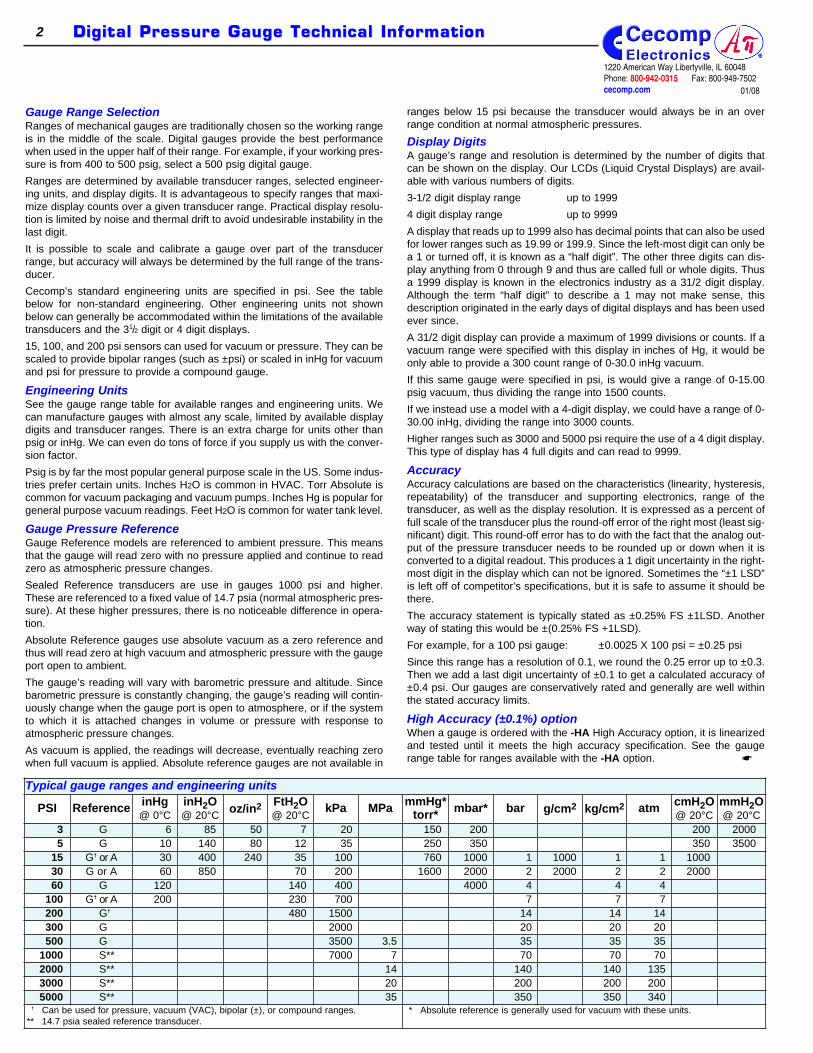
Typical gauge ranges and engineering units
PSI Reference inHg@ 0°C
inH2O@ 20°C oz/in2 FtH2O
@ 20°CkPa MPa mmHg*
torr* mbar* bar g/cm2 kg/cm2 atm cmH2O@ 20°C
mmH2O@ 20°C
3 G 6 85 50 7 20 150 200 200 20005 G 10 140 80 12 35 250 350 350 3500
15 G† or A 30 400 240 35 100 760 1000 1 1000 1 1 100030 G or A 60 850 70 200 1600 2000 2 2000 2 2 200060 G 120 140 400 4000 4 4 4
100 G† or A 200 230 700 7 7 7200 G† 480 1500 14 14 14300 G 2000 20 20 20500 G 3500 3.5 35 35 35
1000 S** 7000 7 70 70 702000 S** 14 140 140 1353000 S** 20 200 200 2005000 S** 35 350 350 340
† Can be used for pressure, vacuum (VAC), bipolar (±), or compound ranges.** 14.7 psia sealed reference transducer.
* Absolute reference is generally used for vacuum with these units.
1220 American Way Libertyville, IL 60048Phone: 800-942-0315 Fax: 800-949-7502cecomp.com
Digital Pressure Gauge Technical InformationDigital Pressure Gauge Technical Information2
01/08
Gauge Range SelectionRanges of mechanical gauges are traditionally chosen so the working rangeis in the middle of the scale. Digital gauges provide the best performancewhen used in the upper half of their range. For example, if your working pres-sure is from 400 to 500 psig, select a 500 psig digital gauge.
Ranges are determined by available transducer ranges, selected engineer-ing units, and display digits. It is advantageous to specify ranges that maxi-mize display counts over a given transducer range. Practical display resolu-tion is limited by noise and thermal drift to avoid undesirable instability in thelast digit.
It is possible to scale and calibrate a gauge over part of the transducerrange, but accuracy will always be determined by the full range of the trans-ducer.
Cecomp’s standard engineering units are specified in psi. See the tablebelow for non-standard engineering. Other engineering units not shownbelow can generally be accommodated within the limitations of the availabletransducers and the 31/2 digit or 4 digit displays.
15, 100, and 200 psi sensors can used for vacuum or pressure. They can bescaled to provide bipolar ranges (such as ±psi) or scaled in inHg for vacuumand psi for pressure to provide a compound gauge.
Engineering UnitsSee the gauge range table for available ranges and engineering units. Wecan manufacture gauges with almost any scale, limited by available displaydigits and transducer ranges. There is an extra charge for units other thanpsig or inHg. We can even do tons of force if you supply us with the conver-sion factor.
Psig is by far the most popular general purpose scale in the US. Some indus-tries prefer certain units. Inches H2O is common in HVAC. Torr Absolute iscommon for vacuum packaging and vacuum pumps. Inches Hg is popular forgeneral purpose vacuum readings. Feet H2O is common for water tank level.
Gauge Pressure ReferenceGauge Reference models are referenced to ambient pressure. This meansthat the gauge will read zero with no pressure applied and continue to readzero as atmospheric pressure changes.
Sealed Reference transducers are use in gauges 1000 psi and higher.These are referenced to a fixed value of 14.7 psia (normal atmospheric pres-sure). At these higher pressures, there is no noticeable difference in opera-tion.
Absolute Reference gauges use absolute vacuum as a zero reference andthus will read zero at high vacuum and atmospheric pressure with the gaugeport open to ambient.
The gauge’s reading will vary with barometric pressure and altitude. Sincebarometric pressure is constantly changing, the gauge’s reading will contin-uously change when the gauge port is open to atmosphere, or if the systemto which it is attached changes in volume or pressure with response toatmospheric pressure changes.
As vacuum is applied, the readings will decrease, eventually reaching zerowhen full vacuum is applied. Absolute reference gauges are not available in
ranges below 15 psi because the transducer would always be in an overrange condition at normal atmospheric pressures.
Display DigitsA gauge’s range and resolution is determined by the number of digits thatcan be shown on the display. Our LCDs (Liquid Crystal Displays) are avail-able with various numbers of digits.
3-1/2 digit display range up to 1999
4 digit display range up to 9999
A display that reads up to 1999 also has decimal points that can also be usedfor lower ranges such as 19.99 or 199.9. Since the left-most digit can only bea 1 or turned off, it is known as a “half digit”. The other three digits can dis-play anything from 0 through 9 and thus are called full or whole digits. Thusa 1999 display is known in the electronics industry as a 31/2 digit display.Although the term “half digit” to describe a 1 may not make sense, thisdescription originated in the early days of digital displays and has been usedever since.
A 31/2 digit display can provide a maximum of 1999 divisions or counts. If avacuum range were specified with this display in inches of Hg, it would beonly able to provide a 300 count range of 0-30.0 inHg vacuum.
If this same gauge were specified in psi, is would give a range of 0-15.00psig vacuum, thus dividing the range into 1500 counts.
If we instead use a model with a 4-digit display, we could have a range of 0-30.00 inHg, dividing the range into 3000 counts.
Higher ranges such as 3000 and 5000 psi require the use of a 4 digit display.This type of display has 4 full digits and can read to 9999.
AccuracyAccuracy calculations are based on the characteristics (linearity, hysteresis,repeatability) of the transducer and supporting electronics, range of thetransducer, as well as the display resolution. It is expressed as a percent offull scale of the transducer plus the round-off error of the right most (least sig-nificant) digit. This round-off error has to do with the fact that the analog out-put of the pressure transducer needs to be rounded up or down when it isconverted to a digital readout. This produces a 1 digit uncertainty in the right-most digit in the display which can not be ignored. Sometimes the “±1 LSD”is left off of competitor’s specifications, but it is safe to assume it should bethere.
The accuracy statement is typically stated as ±0.25% FS ±1LSD. Anotherway of stating this would be ±(0.25% FS +1LSD).
For example, for a 100 psi gauge: ±0.0025 X 100 psi = ±0.25 psi
Since this range has a resolution of 0.1, we round the 0.25 error up to ±0.3.Then we add a last digit uncertainty of ±0.1 to get a calculated accuracy of±0.4 psi. Our gauges are conservatively rated and generally are well withinthe stated accuracy limits.
High Accuracy (±0.1%) optionWhen a gauge is ordered with the -HA High Accuracy option, it is linearizedand tested until it meets the high accuracy specification. See the gaugerange table for ranges available with the -HA option. ☛
Some engineering units with certain display resolutions don’t give any advan-tage with the high accuracy option. For example, a 30 psi gauge with 0.1 res-olution would have the same calculated accuracy in both ±0.25% FS ±1 LSDand ±0.1% FS ±1 LSD versions due to fact that error is rounded up (we can'tignore possible error). A gauge in this range would require a 4 digit display(0.01 resolution) to take advantage of the high accuracy specification.
The High Accuracy option is available for the analog output only on any 3-1/2digit gauge with an analog output. For these gauges the high accuracy lin-earization specification applies only to the analog output and not the display.
CalibrationAll Cecomp gauges are calibrated at the factory on equipment traceable toNIST. There is no need to calibrate the gauge before putting it in service.
Calibration intervals depend entirely upon the customer’s quality standards,thus the factory does not have a recommended calibration interval. Mostindustries check instrument calibration on an annual basis. Actual experiencemay suggest shorter or longer intervals based on severity of service and “asfound” test results while the gauge is being serviced.
It is generally desirable to calibrate the gauge to read zero at zero pressure,and adjust the span to achieve best accuracy over the desired operatingrange. Span is usually adjusted for “best fit” to minimize errors at all testpoints. It is possible to adjust for best accuracy over a narrow pressure range,but be aware that the gauge accuracy specification is based on the entiretransducer range.
The pressure sensor is designed to maintain specifications over its tempera-ture compensated range, usually 0 to 70°C. Deviations in pressure sensoroutput occur as the gauge transducer operates in temperatures that are dif-ferent than normal ambient. This is mainly due to thermal expansion/contrac-tion of the piezoelectric sensing device. Temperature compensation circuitrybuilt into the sensor automatically eliminates for most of the variance. Formost applications the gauge should be adjusted at normal ambient tempera-tures of 20 to 25°C. It is acceptable to calibrate the gauge at the temperatureat which it is to be used.
Sensor Cavity VolumeSensor cavity volume is approximately 0.01 to 0.02 cubic inches. The volumechange over the range of the sensor is negligible.
Gauge IsolatorsYou can use a gauge isolator with Cecomp gauges except for the olderDPG500 series. Cecomp DPG1000, F4 and F16 series gauges have 316stainless steel wetted parts, so often an isolator is not needed unless themedia is incompatible with stainless steel. Chemical compatibility data iscommonly available from online sources or the Compass Corrosion Guide.
Please be aware that a gauge isolator can degrade the accuracy and sensi-tivity of any gauge it is attached to. Refer to the gauge isolator manufactur-er’s data for more information. Your local gauge distributor may be able toassist you with gauge isolator selection, installation, and service.
Please remove the isolator from any gauge you send to us for calibration orservice. Cecomp is not equipped to install, service, or refill gauge isolators.Your local gauge distributor may also be able to recalibrate your Cecompgauge.
Retransmission OutputsSee the gauge data sheet for specific information for using the analog out-puts.
DPG1000 and F4 series retransmission outputs are driven by the transducerrather than the display and thus are true analog outputs. Outputs are filteredto improve noise immunity and have a response time of about 50 msec.
F16 series gauges are microprocessor-based and produce an analog outputwith approximately 12,000 counts over the entire range. This output is updat-ed approximately 16 times per second.Voltage Retransmission - When using the voltage retransmission option, donot allow the resistive load on the output to fall below 5K ohms. Also, avoidlarge capacitive loads (greater that 1000 pF) such as those caused by longruns of shielded cable. For long retransmission runs, use the 4-20 mA optioninstead.Current Retransmission - Be sure to observe the output compliance (volt-age drive) capabilities of the gauge. See the gauge data sheet for output drivecompliance specifications. The compliance, and therefore the maximum loopresistance the output can drive, is a function of the supply voltage to thegauge. Too large a loop resistance will cause the gauge output to “limit” orsaturate before reaching its full 20 mA output.System Grounding with Retransmission - For gauges with retransmission,the power supply (–) lead is tied to the retransmission output ground.Therefore, if a DC supply is used, the power supply (–) lead should be con-sidered common with the retransmission output (–) connection.
Alarm OutputsFor gauges equipped with alarms, see the gauge rear label for the specificalarm configuration and the gauge data sheet for alarm configuration options.Note that most gauges have built-in deadbands (hysteresis) of 1% of span asstandard. The alarm contacts are rated at 1A/24VDC or 0.5A/115VAC. Nointernal fusing is included in the alarm contact circuits. The circuit external tothe gauge alarm outputs should be fused by the user in applications wheregood design practice dictates.
Multiply psi inH2O@ 39.2°F
or 4°C
inH2O@ 60°F or
15.6°C
inH2O@ 68°F or
20°C
ftH2O@ 68°For 20°C
kPa atm(std)
atm(metric)
bar mbar inHg@ 32°F
inHg@ 60°F
cmHg@ 0°C
Torr ormmHg
@ 0°C
kg/cm2 cmH2O@ 4°C
oz/in2
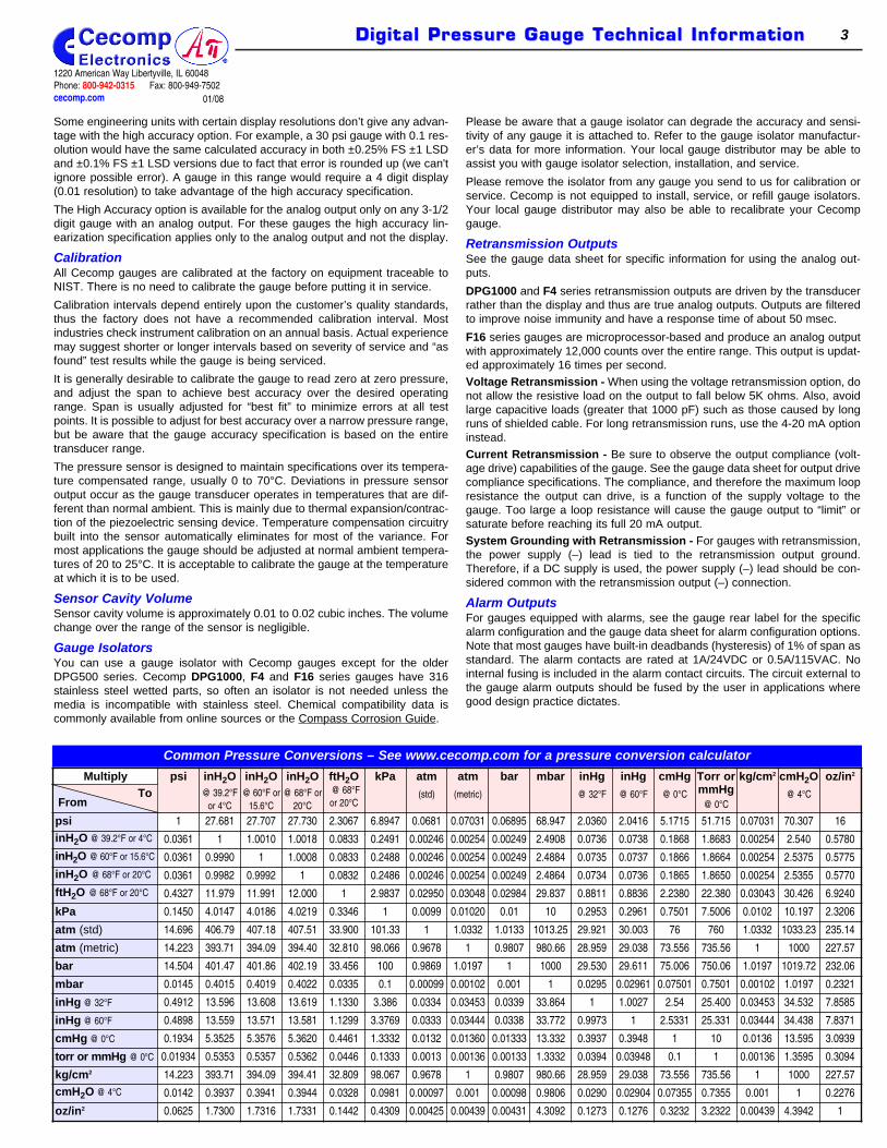
psi 1 27.681 27.707 27.730 2.3067 6.8947 0.0681 0.07031 0.06895 68.947 2.0360 2.0416 5.1715 51.715 0.07031 70.307 16
inH2O @ 39.2°F or 4°C 0.0361 1 1.0010 1.0018 0.0833 0.2491 0.00246 0.00254 0.00249 2.4908 0.0736 0.0738 0.1868 1.8683 0.00254 2.540 0.5780
inH2O @ 60°F or 15.6°C 0.0361 0.9990 1 1.0008 0.0833 0.2488 0.00246 0.00254 0.00249 2.4884 0.0735 0.0737 0.1866 1.8664 0.00254 2.5375 0.5775
inH2O @ 68°F or 20°C 0.0361 0.9982 0.9992 1 0.0832 0.2486 0.00246 0.00254 0.00249 2.4864 0.0734 0.0736 0.1865 1.8650 0.00254 2.5355 0.5770
ftH2O @ 68°F or 20°C 0.4327 11.979 11.991 12.000 1 2.9837 0.02950 0.03048 0.02984 29.837 0.8811 0.8836 2.2380 22.380 0.03043 30.426 6.9240
kPa 0.1450 4.0147 4.0186 4.0219 0.3346 1 0.0099 0.01020 0.01 10 0.2953 0.2961 0.7501 7.5006 0.0102 10.197 2.3206
atm (std) 14.696 406.79 407.18 407.51 33.900 101.33 1 1.0332 1.0133 1013.25 29.921 30.003 76 760 1.0332 1033.23 235.14
atm (metric) 14.223 393.71 394.09 394.40 32.810 98.066 0.9678 1 0.9807 980.66 28.959 29.038 73.556 735.56 1 1000 227.57
bar 14.504 401.47 401.86 402.19 33.456 100 0.9869 1.0197 1 1000 29.530 29.611 75.006 750.06 1.0197 1019.72 232.06
mbar 0.0145 0.4015 0.4019 0.4022 0.0335 0.1 0.00099 0.00102 0.001 1 0.0295 0.02961 0.07501 0.7501 0.00102 1.0197 0.2321
inHg @ 32°F 0.4912 13.596 13.608 13.619 1.1330 3.386 0.0334 0.03453 0.0339 33.864 1 1.0027 2.54 25.400 0.03453 34.532 7.8585
inHg @ 60°F 0.4898 13.559 13.571 13.581 1.1299 3.3769 0.0333 0.03444 0.0338 33.772 0.9973 1 2.5331 25.331 0.03444 34.438 7.8371
cmHg @ 0°C 0.1934 5.3525 5.3576 5.3620 0.4461 1.3332 0.0132 0.01360 0.01333 13.332 0.3937 0.3948 1 10 0.0136 13.595 3.0939
torr or mmHg @ 0°C 0.01934 0.5353 0.5357 0.5362 0.0446 0.1333 0.0013 0.00136 0.00133 1.3332 0.0394 0.03948 0.1 1 0.00136 1.3595 0.3094
kg/cm2 14.223 393.71 394.09 394.41 32.809 98.067 0.9678 1 0.9807 980.66 28.959 29.038 73.556 735.56 1 1000 227.57
cmH2O @ 4°C 0.0142 0.3937 0.3941 0.3944 0.0328 0.0981 0.00097 0.001 0.00098 0.9806 0.0290 0.02904 0.07355 0.7355 0.001 1 0.2276
oz/in2 0.0625 1.7300 1.7316 1.7331 0.1442 0.4309 0.00425 0.00439 0.00431 4.3092 0.1273 0.1276 0.3232 3.2322 0.00439 4.3942 1
Common Pressure Conversions – See www.cecomp.com for a pressure conversion calculator
FromTo
1220 American Way Libertyville, IL 60048Phone: 800-942-0315 Fax: 800-949-7502cecomp.com
Digital Pressure Gauge Technical InformationDigital Pressure Gauge Technical Information 3
01/08

Gauge Ranges 31/2 Digit Display, DPG1000, ARM, F4 Series 4-Digit Display F16 Digi MaxPounds perSquare Inch
Equivalentpsi
DisplayResolution
±0.25% ±1 LSDAccuracy
±0.1% ±1 LSDAccuracy
DisplayResolution
±0.25% ±1 LSDAccuracy
±0.1% ±1 LSDAccuracy
–30INHG/15PSIG ±15.0 0.1 ±0.2 psi n/a 0.01 ±0.09 psi n/a–30INHG/100PSIG –15.0/100.0 0.1 ±0.4 psi n/a 0.1 ±0.4 psi n/a–30INHG/200PSIG –15.0/199.9 0.1 ±0.7 psi n/a 0.1 ±0.7 psi n/a
3PSIG 3.00 0.01 ±0.02 n/a 0.001 ±0.009 n/a5PSIG 5.00 0.01 ±0.03 ±0.02 0.001 ±0.014 ±0.006
15PSIA 15.00 abs 0.01 ±0.05 n/a 0.01 ±0.05 n/a15PSIGVAC –15.00 0.01 ±0.05 ±0.03 0.01 ±0.05 ±0.03
±15PSIG ±15.0 0.1 ±0.2 n/a 0.01 ±0.09 n/a15PSIG 15.00 0.01 ±0.05 ±0.03 0.01 ±0.05 ±0.0330PSIA 30.0 abs 0.1 ±0.2 n/a 0.01 ±0.09 n/a30PSIG 30.0 0.1 ±0.2 n/a 0.01 ±0.09 ±0.0460PSIG 60.0 0.1 ±0.3 ±0.2 0.01 ±0.16 ±0.07
100PSIA 100.0 abs 0.1 ±0.4 n/a 0.1 ±0.4 n/a100PSIG 100.0 0.1 ±0.4 ±0.2 0.1 ±0.4 ±0.2200PSIG 199.9/200.0 0.1 ±0.6 ±0.3 0.1 ±0.6 ±0.3300PSIG 300 1 ±2 n/a 0.1 ±0.9 ±0.4500PSIG 500 1 ±3 ±2 0.1 ±1.4 ±0.6
1000PSIG 1000 1 ±4 ±2 1 ±4 ±22000PSIG 1999/2000 1 ±6 ±3 1 ±6 ±33000PSIG 3000 1 ±9 ±4 1 ±9 ±45000PSIG 5000 1 ±14 ±6 1 ±14 ±6
Inches HgMercury @ 0°C
Equivalentpsi
DisplayResolution
±0.25% ±1 LSDAccuracy
±0.1% ±1 LSDAccuracy
DisplayResolution
±0.25% ±1 LSDAccuracy
±0.1% ±1 LSDAccuracy
6INHGG 2.95 0.01 ±0.03 n/a 0.001 ±0.017 n/a10INHGG 4.91 0.01 ±0.04 ±0.03 0.01 ±0.04 ±0.0330INHGA 14.73 abs 0.1 ±0.2 n/a 0.01 ±0.09 n/a30INHGVAC –14.73 0.1 ±0.2 n/a 0.01 ±0.09 ±0.04
±30INHGG ±14.73 0.1 ±0.3 n/a 0.01 ±0.17 n/a30INHGG 14.73 0.1 ±0.2 n/a 0.01 ±0.09 ±0.0560INHGA 29.5 abs 0.1 ±0.3 n/a 0.01 ±0.17 n/a60INHGG 29.5 0.1 ±0.3 ±0.2 0.01 ±0.17 ±0.08
120INHGG 58.9 0.1 ±0.5 ±0.3 0.1 ±0.5 ±0.3200INHGA 98.2 abs 0.1 ±0.7 n/a 0.1 ±0.7 n/a200INHGG 98.2 0.1 ±0.7 ±0.4 0.1 ±0.7 ±0.4Inches H2O
@ 20°CEquivalent
psiDisplay
Resolution±0.25% ±1 LSD
Accuracy±0.1% ±1 LSD
AccuracyDisplay
Resolution±0.25% ±1 LSD
Accuracy±0.1% ±1 LSD
Accuracy85INH2OG 3.07 0.1 ±0.4 n/a 0.1 ±0.4 n/a
140INH2OG 5.05 0.1 ±0.5 ±0.3 0.1 ±0.5 ±0.3400INH2OA 14.42 abs 1 ±3 n/a 0.1 ±1.2 n/a400INH2OVAC –14.42 1 ±3 ±2 0.1 ±1.2 ±0.6
±400INH2OG ±14.42 1 ±4 n/a 1 ±4 n/a400INH2OG 14.42 1 ±3 ±2 0.1 ±1.2 ±0.6850INH2OG 30.7 1 ±4 ±2 1 ±4 ±2
Feet H2O@ 20°C
Equivalentpsi
DisplayResolution
±0.25% ±1 LSDAccuracy
±0.1% ±1 LSDAccuracy
DisplayResolution
±0.25% ±1 LSDAccuracy
±0.1% ±1 LSDAccuracy
7FTH2O 3.03 0.01 ±0.03 n/a 0.001 ±0.019 n/a12FTH2O 5.20 0.01 ±0.04 ±0.03 0.01 ±0.04 ±0.0335FTH2O 15.2 0.1 ±0.2 n/a 0.01 ±0.10 ±0.0570FTH2O 30.3 0.1 ±0.3 ±0.2 0.01 ±0.19 ±0.08
140FTH2O 60.7 0.1 ±0.5 ±0.3 0.1 ±0.5 ±0.3230FTH2O 99.7 1 ±2 n/a 0.1 ±0.7 ±0.4480FTH2O 208 1 ±3 ±2 0.1 ±1.3 ±0.6
Ounces perSquare Inch
Equivalentpsi
DisplayResolution
±0.25% ±1 LSDAccuracy
±0.1% ±1 LSDAccuracy
DisplayResolution
±0.25% ±1 LSDAccuracy
±0.1% ±1 LSDAccuracy
50ZING 3.13 0.1 ±0.3 n/a 0.01 ±0.14 n/a80ZING 5.00 0.1 ±0.3 ±0.2 0.1 ±0.3 ±0.2
240ZING 15.0 1 ±2 n/a 0.1 ±0.7 ±0.4
1220 American Way Libertyville, IL 60048Phone: 800-942-0315 Fax: 800-949-7502cecomp.com
Digital Pressure Gauge Ranges and AccuraciesDigital Pressure Gauge Ranges and Accuracies4
01/08

Gauge Ranges 31/2 Digit Display, DPG1000, ARM, F4 Series 4-Digit Display F16 Digi Max
KiloPascals Equivalentpsi
DisplayResolution
±0.25% ±1 LSDAccuracy
±0.1% ±1 LSDAccuracy
DisplayResolution
0.25% ±1 LSDAccuracy
±0.1% ±1 LSDAccuracy
–100V/700KPA –15/102 1 ±3 n/a ±3 ±3 n/a20KPAG 2.90 0.01 ±0.07 n/a 0.01 ±0.07 n/a35KPAG 5.08 0.1 ±0.2 n/a 0.01 ±0.10 ±0.05
100KPAA 14.5 abs 0.1 ±0.4 n/a 0.1 ±0.4 n/a100KPAVAC –14.5 0.1 ±0.4 ±0.3 0.1 ±0.4 ±0.3
±100KPAG ±14.5 0.1 ±0.7 n/a 0.1 ±0.7 n/a100KPAG 14.5 0.1 ±0.4 ±0.3 0.1 ±0.4 ±0.3200KPAA 29.0 abs 0.1 ±0.7 n/a 0.1 ±0.7 n/a200KPAG 29.0 0.1 ±0.7 ±0.4 0.1 ±0.7 ±0.4400KPAG 58 1 ±3 ±2 0.1 ±1.2 ±0.6700KPAA 102 abs 1 ±3 n/a 0.1 ±1.9 n/a700KPAG 102 1 ±3 ±2 0.1 ±1.9 ±0.8
1500KPAG 218 1 ±5 ±3 1 ±5 ±32000KPAG 290 1 ±7 ±4 1 ±7 ±43500KPAG 508 1 ±10 ±5 1 ±10 ±57000KPAG 1015 1 ±19 ±8 1 ±19 ±8
MegaPascals Equivalentpsi
DisplayResolution
±0.25% ±1 LSDAccuracy
±0.1% ±1 LSDAccuracy
DisplayResolution
±0.25% ±1 LSDAccuracy
±0.1% ±1 LSDAccuracy
3.5MPAG 508 0.01 ±0.02 n/a 0.001 ±0.01 ±0.0057MPAG 1015 0.01 ±0.03 ±0.02 0.001 ±0.019 ±0.008
14MPAG 2031 0.01 ±0.05 ±0.03 0.01 ±0.05 ±0.0320MPAG 2901 0.01 ±0.07 ±0.04 0.01 ±0.07 ±0.0435MPAG 5076 0.1 ±0.2 n/a 0.01 ±0.10 ±0.05
Millibars Equivalentpsi
DisplayResolution
±0.25% ±1 LSDAccuracy
±0.1% ±1 LSDAccuracy
DisplayResolution
±0.25% ±1 LSDAccuracy
±0.1% ±1 LSDAccuracy
200MBARG 2.90 0.1 ±0.7 n/a 0.1 ±0.7 n/a350MBARG 5.08 1 ±2 n/a 0.1 ±1.0 ±0.5
1000MBARA 14.5 abs 1 ±4 n/a 1 ±4 n/a±1000MBARG ±14.5 1 ±7 n/a 1 ±7 n/a
1000MBARG 14.5 1 ±4 ±3 1 ±4 ±32000MBARA 29.0 abs 1 ±7 n/a 1 ±7 n/a2000MBARG 29.0 1 ±7 ±4 1 ±7 ±44000MBARG 58.0 1 ±12 ±6 1 ±12 ±6
Bar Equivalentpsi
DisplayResolution
±0.25% ±1 LSDAccuracy
±0.1% ±1 LSDAccuracy
DisplayResolution
±0.25% ±1 LSDAccuracy
±0.1% ±1 LSDAccuracy
–1V/7BAR –14.5/101.5 0.01 ±0.04 n/a 0.01 ±0.04 n/a1BARA 14.50 abs 0.001 ±0.004 n/a 0.001 ±0.004 n/a
±1BARG ±14.50 0.001 ±0.007 n/a 0.001 ±0.004 n/a1BARVAC –14.50 0.001 ±0.004 ±0.003 0.001 ±0.004 ±0.0031BARG 14.50 0.001 ±0.004 ±0.003 0.001 ±0.004 ±0.0032BARA 29.0 abs 0.001 ±0.007 n/a 0.001 ±0.007 n/a2BARG 29.0 0.001 ±0.007 ±0.004 0.001 ±0.007 ±0.0044BARG 58.0 0.01 ±0.03 ±0.02 0.001 ±0.012 ±0.0067BARA 101.5 abs 0.01 ±0.03 n/a 0.001 ±0.019 n/a7BARG 101.5 0.01 ±0.03 ±0.02 0.001 ±0.019 ±0.008
14BARG 203 0.01 ±0.05 ±0.03 0.01 ±0.05 ±0.0320BARG 290 0.01 ±0.07 ±0.04 0.01 ±0.07 ±0.0435BARG 508 0.1 ±0.2 n/a 0.01 ±0.10 ±0.0570BARG 1015 0.1 ±0.3 ±0.2 0.01 ±0.19 ±0.08
140BARG 2031 0.1 ±0.5 ±0.3 0.1 ±0.5 ±0.3200BARG 2901 0.1 ±0.7 ±0.4 0.1 ±0.7 ±0.4350BARG 5076 1 ±2 n/a 0.1 ±1.0 ±0.5
1220 American Way Libertyville, IL 60048Phone: 800-942-0315 Fax: 800-949-7502cecomp.com
Digital Pressure Gauge Technical InformationDigital Pressure Gauge Technical Information 5
01/08

Gauge Ranges 31/2-Digit Display, DPG1000, ARM, F4 Series 4-Digit Display F16 Digi MaxKilograms per
cm2Equivalent
psiDisplay
Resolution±0.25% ±1 LSD
Accuracy±0.1% ±1 LSD
AccuracyDisplay
Resolution±0.25% ±1 LSD
Accuracy±0.1% ±1 LSD
Accuracy1KGCMA 14.22 abs 0.001 ±0.004 n/a 0.001 ±0.004 n/a
±1KGCMG ±14.22 0.001 ±0.007 n/a 0.001 ±0.007 n/a1KGCMG 14.22 0.001 ±0.004 ±0.003 0.001 ±0.004 ±0.0032KGCMA 28.4 abs 0.001 ±0.007 n/a 0.001 ±0.007 n/a2KGCMG 28.4 0.001 ±0.007 ±0.004 0.001 ±0.007 ±0.0044KGCMG 56.9 0.01 ±0.03 ±0.02 0.001 ±0.012 ±0.0067KGCMA 99.6 abs 0.01 ±0.03 n/a 0.001 ±0.019 n/a7KGCMG 99.6 0.01 ±0.03 ±0.02 0.001 ±0.019 ±0.009
14KGCMG 199.1 0.01 ±0.05 ±0.03 0.01 ±0.05 ±0.0320KGCMG 284 0.01 ±0.07 ±0.04 0.01 ±0.07 ±0.0435KGCMG 498 0.1 ±0.2 n/a 0.01 ±0.10 ±0.0570KGCMG 996 0.1 ±0.3 ±0.2 0.01 ±0.19 ±0.09
140KGCMG 1991 0.1 ±0.5 ±0.3 0.1 ±0.5 ±0.3200KGCMG 2845 0.1 ±0.7 ±0.4 0.1 ±0.7 ±0.4350KGCMG 4978 1 ±2 n/a 0.1 ±1.0 ±0.5
Grams percm2
Equivalentpsi
DisplayResolution
±0.25% ±1 LSDAccuracy
±0.1% ±1 LSDAccuracy
DisplayResolution
±0.25% ±1 LSDAccuracy
±0.1% ±1 LSDAccuracy
1000GCMA 14.22 abs 1 ±4 n/a 1 ±4 n/a1000GCMG 14.22 1 ±4 ±3 1 ±4 ±31999GCMA 29.9 abs 1 ±7 n/a 1 ±7 n/a1999GCMA 29.9 abs 1 ±7 n/a 1 ±7 n/a2100GCMG 29.9 n/a n/a n/a 1 ±7 ±42100GCMG 29.9 n/a n/a n/a 1 ±7 ±4mmHg or TorrMercury @ 0°C
Equivalentpsi
DisplayResolution
±0.25% ±1 LSDAccuracy
±0.1% ±1 LSDAccuracy
DisplayResolution
±0.25% ±1 LSDAccuracy
±0.1% ±1 LSDAccuracy
150MMHGG 2.90 0.1 ±0.5 n/a 0.1 ±0.5 n/a260MMHGG 5.03 1 ±2 n/a 0.1 ±0.8 ±0.4760TORRA 14.7 abs 1 ±3 n/a 0.1 ±2.1 n/a760MMHGA 14.7 abs 1 ±3 n/a 0.1 ±2.1 n/a760MMHGVAC –14.7 1 ±3 n/a 0.1 ±2.1 n/a760MMHGG 14.7 1 ±3 ±2 0.1 ±2.1 ±0.91600MMHGA 30.9 abs 1 ±5 n/a 1 ±5 n/a1600MMHGG 30.9 1 ±5 ±3 1 ±5 ±3
cm H2O @ 20°C Equivalentpsi
DisplayResolution
±0.25% ±1 LSDAccuracy
±0.1% ±1 LSDAccuracy
DisplayResolution
±0.25% ±1 LSDAccuracy
±0.1% ±1 LSDAccuracy
200CMH2OG 2.84 0.1 ±0.7 n/a 0.1 ±0.7 n/a350CMH2OG 4.97 1 ±2 n/a 0.1 ±1.0 ±0.5
1000CMH2OG 14.2 1 ±4 ±3 1 ±4 ±31999CMH2OG 28.4 1 ±7 ±4 1 ±7 ±42100CMH2OG 29.8 n/a n/a n/a 1 ±7 ±4
mm H2O@ 20°C Equivalentpsi
DisplayResolution
±0.25% ±1 LSDAccuracy
±0.1% ±1 LSDAccuracy
DisplayResolution
±0.25% ±1 LSDAccuracy
±0.1% ±1 LSDAccuracy
1999MMH2OG 2.84 1 ±7 n/a 1 ±7 n/a2100MMH2OG 2.98 n/a n/a n/a 1 ±7 n/a3500MMH2OG 4.97 n/a n/a n/a 1 ±10 ±5
Atmospheresstd
Equivalentpsi
DisplayResolution
±0.25% ±1 LSDAccuracy
±0.1% ±1 LSDAccuracy
DisplayResolution
±0.25% ±1 LSDAccuracy
±0.1% ±1 LSDAccuracy
1ATMG 14.70 0.001 ±0.004 ±0.003 0.001 ±0.004 ±0.0032ATMG 29.39 0.01 ±0.02 ±0.02 0.001 ±0.007 ±0.0044ATMG 58.8 0.01 ±0.03 ±0.02 0.001 ±0.012 ±0.0067ATMG 102.9 0.01 ±0.03 ±0.02 0.001 ±0.019 ±0.008
14ATMG 206 0.01 ±0.05 ±0.03 0.01 ±0.05 ±0.0320ATMG 294 0.01 ±0.07 ±0.04 0.01 ±0.07 ±0.0435ATMG 514 0.1 ±0.2 n/a 0.01 ±0.10 ±0.0570ATMG 1029 0.1 ±0.3 ±0.2 0.01 ±0.19 ±0.08
135ATMG 1984 0.1 ±0.5 ±0.3 0.1 ±0.5 ±0.3200ATMG 2939 0.1 ±0.7 ±0.4 0.1 ±0.7 ±0.4340ATMG 4997 1 ±2 n/a 0.1 ±1.0 ±0.5
1220 American Way Libertyville, IL 60048Phone: 800-942-0315 Fax: 800-949-7502cecomp.com
Digital Pressure Gauge Ranges and AccuraciesDigital Pressure Gauge Ranges and Accuracies6
01/08

PrecautionsInstall or remove gauge using wrench on hex fitting only. Do not attempt totighten or loosen by turning housing or any other part of the gauge.
Use fittings appropriate for the pressure range of the gauge as indicated onthe rear label.
Do not apply vacuum to gauges not designed for vacuum operation.
Due to the hardness of 316 stainless steel, it is recommended that a threadsealant be used to ensure leak-free operation.
NEVER insert objects into the gauge port or blow out with compressed air.Permanent damage not covered by warranty will result to the sensor.
NEVER connect low-voltage-powered gauge wires directly to 115 VAC orpermanent damage not covered by warranty will result. Common 24 VACtransformers often supply over 32 VAC unless they are loaded to 80% ofrated capacity. Over voltage may result in damage.
These products do not contain user serviceable parts except for those withreplaceable batteries as specified in the instructions. Contact us for repairs,service, or refurbishment.
Preparation1. Please refer to the appropriate data sheet for specifications, installation,
wiring, and operating instructions.
2. Calibration should only be performed by qualified individuals using appro-priate calibration standards and procedures.
3. The calibration equipment should be at least four times more accuratethan the gauge being calibrated. The calibration system must be able togenerate and measure pressure/vacuum over the full range of the gauge.A vacuum pump able to produce a vacuum of 10 microns (0.01 torr or 10millitorr) or lower is required for vacuum and absolute gauges.
4. It is good practice to install fresh batteries before calibrating battery-pow-ered gauges.
For low-voltage powered gauges connect to a the appropriate power sup-ply as indicated on the gauge or data sheet. The supply voltage has neg-ligible effects on the gauge calibration as long as it is within the stated volt-age ranges. Over voltage may result in damage.
5. Allow the gauge to equalize to normal room temperature before calibra-tion.
Calibration Potentiometer AccessAccess the calibration potentiometers based on the model as shown below.Contact Customer Service to purchase replacement potentiometer covers.
Models with top potentiometers: Remove label on top of gauge toexpose opening with calibration potentiometers. This label may be reusedmany times if kept clean. See rear label of gauge for potentiometer iden-tification.
Models with front potentiometers: Remove the black plastic caps toexpose the calibration potentiometers.
NEMA 4X models with front potentiometers: Unscrew nylon screwswith o-rings to expose the calibration potentiometers.
Calibration of Battery-Powered ModelsDPG1000B, DPG1000BBL, F4B, F4BBL, ARM760B,ARM760BBL1. It is good practice to install fresh batteries before calibrating battery-pow-
ered gauges.
2. Zero for gauge reference pressure or vacuum gauges: With the gaugeport open to atmosphere, adjust the Zero potentiometer for a display indi-cation of zero.
Zero for absolute reference gauges: Apply full vacuum to the gauge.Adjust the Zero potentiometer for a display indication of zero.
3. Span for gauge reference pressure gauges and absolute referencegauges: Apply full-scale pressure and adjust the Span potentiometer fora display indication equal to full-scale pressure.
Span for gauge reference vacuum gauges: Apply full vacuum to thegauge. Adjust the Span potentiometer for a display indication equal to full-scale vacuum.
4. Verify pressure indications at 0%, 25%, 50%, 75%, and 100% of full scaleand repeat calibration as needed to achieve best accuracy over desiredoperating range.
End of this procedure
Calibration of Low-Voltage Powered ModelsDPG1000AD, DPG1000ADBL, F4AD, F4ADBL, ARM760AD,ARM760ADBL, DPG1000ADA1. Low-voltage powered gauges must be connected to 8-24 VAC 50/60 Hz
or 9-32 VDC during the calibration procedure. The supply voltage hasnegligible effects on the gauge calibration as long as it is within the statedvoltage ranges.
NEVER connect gauge wires directly to 115 VAC or permanent damagenot covered by warranty will result. Common 24 VAC transformers oftensupply over 32 VAC unless they are loaded to 80% of rated capacity. Overvoltage may result in damage.
2. Zero for gauge reference pressure or vacuum gauges: With the gaugeport open to atmosphere, adjust the Zero potentiometer for a display indi-cation of zero.
Zero for absolute reference gauges: Apply full vacuum to the gauge.Adjust the Zero potentiometer for a display indication of zero.
3. Span for gauge reference pressure gauges and absolute referencegauges: Apply full-scale pressure and adjust the Span potentiometer fora display indication equal to full-scale pressure.
Span for gauge reference vacuum gauges: Apply full vacuum to thegauge. Adjust the Span potentiometer for a display indication equal to full-scale vacuum.
4. Verify pressure indications at 0%, 25%, 50%, 75%, and 100% of full scaleand repeat calibration as needed to achieve best accuracy over desiredoperating range.
End of this procedure
1220 American Way Libertyville, IL 60048Phone: 800-942-0315 Fax: 800-949-7502cecomp.com
Digital Pressure Gauge Calibration ProceduresDigital Pressure Gauge Calibration ProceduresGauges with Single Line 3-1/2 or 4 Digit LCDBattery Powered: DPG1000B, DPG1000BBL, F4B, F4BBL, ARM760B, ARM760BBLLow Voltage Powered: DPG1000AD, DPG1000ADBL, F4AD, F4ADBL, ARM760AD,
ARM760ADBL, DPG1000ADA
7
01/08
Top Potentiometers Front Potentiometers Front PotentiometersNEMA 4X

PrecautionsInstall or remove gauge using wrench on hex fitting only. Do not attempt totighten or loosen by turning housing or any other part of the gauge.
Use fittings appropriate for the pressure range of the gauge. The gauge rangeis indicated on the rear label and is indicated on the display during power-up.
Do not apply vacuum to gauges not designed for vacuum operation.
Due to the hardness of 316 stainless steel, it is recommended that a threadsealant be used to ensure leak-free operation.
NEVER insert objects into the gauge port or blow out with compressed air.Permanent damage not covered by warranty will result to the sensor.
NEVER connect low-voltage-powered gauge wires directly to 115 VAC orpermanent damage not covered by warranty will result. Common 24 VACtransformers often supply over 32 VAC unless they are loaded to 80% ofrated capacity. Over voltage may result in damage.
These products do not contain user serviceable parts except for those withreplaceable batteries as specified in the instructions. Contact us for repairs,service, or refurbishment.
Preparation1. Please refer to the appropriate data sheet for specifications, installation,
wiring, and operating instructions.
2. Calibration should only be performed by qualified individuals using appro-priate calibration standards and procedures.
3. The calibration equipment should be at least four times more accuratethan the gauge being calibrated. The calibration system must be able togenerate and measure pressure/vacuum over the full range of the gauge.A vacuum pump able to produce a vacuum of 10 microns (0.01 torr or 10millitorr) or lower is required for vacuum and absolute gauges.
4. It is good practice to install fresh batteries before calibrating battery-pow-ered gauges.
For low-voltage powered gauges connect to a the appropriate power sup-ply as indicated on the gauge or data sheet. The supply voltage has neg-ligible effects on the gauge calibration as long as it is within the stated volt-age ranges. Over voltage may result in damage.
5. Allow the gauge to equalize to normal room temperature before calibra-tion.
Entering Calibration Mode1. Note the locations of the calibration mode jumper points and the three cal-
ibration potentiometers. IMPORTANT: Do NOT adjust the calibrationpotentiometers unless the gauge is in the calibration mode.
2. To enter the calibration mode, place a jumper wire between the calibrationmode jumper points as shown below.
3. Press the front push button to power up the gauge. The display first indi-cates the gauge’s full-scale pressure range, tests all display segments,and then indicates CAL to indicate that the gauge is in the calibrationmode.
4. The display will then indicate the current pressure reading, updatingapproximately 3 times per second. The jumper can be removed at thistime and the gauge will remain in the calibration mode until powered downmanually.
While in the calibration mode, the auto shutoff timer is disabled, the OneTouch Zero (used on gauge reference models only) is disabled, and thecalibration potentiometers remain active. In normal operation, the calibra-tion potentiometers are only read during initialization to conserve power.
Calibration1. Zero for gauge reference pressure or vacuum gauges: With the gauge
port open to atmosphere, adjust the Zero potentiometer for a display indi-cation of zero.
Zero for absolute reference gauges: Apply full vacuum to the gauge.Adjust the Zero potentiometer for a display indication of zero.
2. Span for gauge reference pressure gauges and absolute referencegauges: Apply full-scale pressure and adjust the Span potentiometer fora display indication equal to full-scale pressure.
Span for gauge reference vacuum gauges: Apply full vacuum to thegauge. Adjust the Span potentiometer for a display indication equal to full-scale vacuum.
3. Apply 50% full-scale pressure (or vacuum as appropriate) and adjust thesingle-turn Linearization potentiometer (marked Lin on the circuit board)for a display indication equal to 50% of full-scale pressure.
4. Verify pressure indications at 0%, 25%, 50%, 75%, and 100% of full scale.
5. Remove the jumper between the calibration mode terminals following cal-ibration. Failure to remove the jumper will greatly reduce battery life.
6. Turn off gauge power to return gauge to normal operating mode.
7. Replace the rear cover and screws, taking care not to pinch the powerleads between the case and the rear cover.
Zero LinSpan
Insert Jumper Wirefor Cal Mode
0 SpanMid-Point
FullScale
Zero and SpanCorrection Only
Ideal(Straight Line)
With Mid-PointCorrection
Actual Pressure
Indi
cate
d Pr
essu
re
0
Gauge Calibration with Mid-Point Linearization Correction
1220 American Way Libertyville, IL 60048Phone: 800-942-0315 Fax: 800-949-7502cecomp.com
Digital Pressure Gauge Calibration ProceduresDigital Pressure Gauge Calibration ProceduresGauge with 2 Line LCD and Internal PotentiometersBattery Powered: DPG1000B, DPG1000BBL, F4B, F4BBL, F16B, F16BBLLow Voltage Powered: DPG1000AD, DPG1000ADBL, F4AD, F4ADBL, F16AD, F16ADBL
8
01/08

PrecautionsInstall or remove gauge using wrench on hex fit-ting only. Do not attempt to tighten or loosen byturning housing or any other part of the gauge.
Use fittings appropriate for the pressure range ofthe gauge. The gauge range is indicated on therear label and is indicated on the display duringpower-up.
Do not apply vacuum to gauges not designed forvacuum operation.
Due to the hardness of 316 stainless steel, it isrecommended that a thread sealant be used toensure leak-free operation.
NEVER insert objects into the gauge port or blow out with compressed air.Permanent damage not covered by warranty will result to the sensor.
NEVER connect low-voltage-powered gauge wires directly to 115 VAC or perma-nent damage not covered by warranty will result. Common 24 VAC transformersoften supply over 32 VAC unless they are loaded to 80% of rated capacity. Overvoltage may result in damage.
These products do not contain user serviceable parts except for those withreplaceable batteries as specified in the instructions. Contact us for repairs, serv-ice, or refurbishment.
Preparation1. Please refer to the appropriate data sheet for specifications, installation, wiring,
and operating instructions.
2. Calibration should only be performed by qualified individuals using appropriatecalibration standards and procedures.
3. The calibration equipment should be at least four times more accurate than thegauge being calibrated. The calibration system must be able to generate andmeasure pressure/vacuum over the full range of the gauge. A vacuum pumpable to produce a vacuum of 10 microns (0.01 torr or 10 millitorr) or lower isrequired for vacuum and absolute gauges.
4. It is good practice to install fresh batteries before calibrating battery-poweredgauges.
For low-voltage powered gauges connect to a the appropriate power supply asindicated on the gauge or data sheet. The supply voltage has negligible effectson the gauge calibration as long as it is within the stated voltage ranges. Overvoltage may result in damage.
5. Allow the gauge to equalize to normal room temperature before calibration.
Entering the Calibration Mode1. Remove the screws on the back of
the unit and remove cover andnote the locations of the two inter-nal calibration buttons marked UPand DOWN. These buttons are dis-abled unless the gauge is in cali-bration mode.
2. Battery-powered gaugesWith the gauge off, press and holdthe DOWN calibration button, andalso press the front button to powerup the gauge in calibration mode.
Low-voltage powered gaugesPress and hold the DOWN calibra-tion button, and also press andhold the front button to reset thegauge and switch it into calibration mode.
Calibration Mode Functions1. The display first indicates the gauge’s full-scale pressure range, tests all dis-
play segments, and then indicates CAL to indicate that the gauge is in the cal-ibration mode. Release all buttons.
2. The display will then indicate the current pressure reading, updating approxi-mately 3 times per second. The gauge will remain in the calibration mode untilpowered down or reset manually. While in the calibration mode, the shutofftimer, One Touch Zero (gauge reference models only), Min/Max (for applicablemodels) are all disabled, and the calibration buttons are active.
3. Each press of the UP or DOWN button makes a small correction, which maynot always be indicated on the digital display. Press and hold the button for onesecond or longer to make larger continuous corrections. The display of the
gauge being calibrated is adjusted to match the calibrator’s setting or readout.
4. If the battery pack is unplugged or the power removed during calibration, cali-bration settings will not be saved.
Gauge Reference Gauges (3 Points)1. With the gauge port open to atmosphere, the character display will alternate
between ZERO and CAL. Press the UP and DOWN buttons to obtain a displayindication of zero.
2. Apply full-scale pressure. The character display will alternate between +SPANand CAL. Press the UP and DOWN buttons to obtain a display indication equalto full-scale pressure.
3. Apply 50% of full-scale pressure. The character display will alternate between+MID and CAL. Press the UP and DOWN buttons to obtain a display indicationequal to 50% of full-scale pressure.
Absolute Reference Gauges (3 Points)1. Apply full vacuum to the gauge. The character display will alternate between
ZERO and CAL. Press the UP and DOWN buttons to obtain a display indica-tion of zero.
2. Apply full-scale pressure. The character display will alternate between +SPANand CAL. Press the UP and DOWN buttons to obtain a display indication equalto full-scale pressure.
3. Apply 50% of full-scale pressure. The character display will alternate between+MID and CAL. Press the UP and DOWN buttons to obtain a display indicationequal to 50% of full-scale pressure.
Bipolar (±) and –30inHg/15psig Compound Ranges (5 Points)1. With the gauge port open to atmosphere, the character display will alternate
between ZERO and CAL. Press the UP and DOWN buttons to obtain a displayindication of zero.
2. Apply full-scale positive pressure. The character display will alternate between+SPAN and CAL. Press the UP and DOWN buttons to obtain a display indica-tion equal to full-scale pressure.
3. Apply 50% of full-scale positive pressure. The character display will alternatebetween +MID and CAL. Press the UP and DOWN buttons to obtain a displayindication equal to 50% of full-scale pressure.
4. Apply full vacuum. The character display will alternate between –SPAN andCAL. Press the UP and DOWN buttons to obtain a display indication equal tothe full vacuum reading.
5. Apply 50% of the full-scale vacuum range (for example, –7.4 psi for a ±15 psigauge). The character display will alternate between –MID and CAL. Press theUP and DOWN buttons to obtain a display indication equal to 50% of full-scalevacuum.
–30inHg/100psig and –30inHg/200psig Compound (4 Points)1. With the gauge port open to atmosphere, the character display will alternate
between ZERO and CAL. Press the UP and DOWN buttons to obtain a displayindication of zero.
2. Apply full-scale positive pressure. The character display will alternate between+SPAN and CAL. Press the UP and DOWN buttons to obtain a display indica-tion equal to full-scale pressure.
3. Apply 50% of full-scale positive pressure. The character display will alternatebetween +MID and CAL. Press the UP and DOWN buttons to obtain a displayindication equal to 50% of full-scale pressure.
4. Apply full vacuum. The character display will alternate between –SPAN andCAL. Press the UP and DOWN buttons to obtain a display indication equal tothe full vacuum reading.
Exit Calibration Mode and Verify Calibration1. Battery-powered gauges: Exit the calibration mode and save the calibration
data by pressing and holding the front button until the display indicates OFF.
Low-voltage powered gauges: Exit the calibration mode and save the cali-bration data by pressing and holding the front button until the gauge resets andpowers up normally.
2. Verify pressure indications at 0%, 25%, 50%, 75%, and 100% of full scale.
3. Replace the rear cover and screws, taking care not to pinch the power leadsbetween the case and the rear cover.
DOWN UP
1220 American Way Libertyville, IL 60048Phone: 800-942-0315 Fax: 800-949-7502cecomp.com
Digital Pressure Gauge Calibration ProceduresDigital Pressure Gauge Calibration ProceduresGauges with 2 Line LCD and Internal Push ButtonsBattery Powered: DPG1000B, DPG1000BBL, F4B, F4BBL, F16B, F16BBLLow Voltage Powered: DPG1000AD, DPG1000ADBL, F4AD, F4ADBL, F16AD, F16ADBL
9
01/08

PrecautionsInstall or remove gauge using wrench on hex fitting only. Do not attempt totighten or loosen by turning housing or any other part of the gauge.
Use fittings appropriate for the pressure range of the gauge as indicated onthe rear label.
Do not apply vacuum to gauges not designed for vacuum operation.
Due to the hardness of 316 stainless steel, it is recommended that a threadsealant be used to ensure leak-free operation.
NEVER insert objects into the gauge port or blow out with compressed air.Permanent damage not covered by warranty will result to the sensor.
NEVER connect low-voltage-powered gauge wires directly to 115 VAC orpermanent damage not covered by warranty will result.
These products do not contain user serviceable parts. Contact us for repairs,service, or refurbishment.
Preparation1. Please refer to the DPG1000L or F4L series data sheet for specifications,
installation, wiring, and operating instructions.
2. Calibration should only be performed by qualified individuals using appro-priate calibration standards and procedures.
3. The calibration equipment should be at least four times more accuratethan the gauge being calibrated. The calibration system must be able togenerate and measure pressure/vacuum over the full range of the gauge.A vacuum pump able to produce a vacuum of 10 microns (0.01 torr or 10millitorr) or lower is required for vacuum and absolute gauges.
4. Connect to a 9-32 VDC power supply during the calibration procedure.The supply voltage has negligible effects on the gauge calibration as longas it is within the stated voltage ranges. Over voltage may result in dam-age.
5. Allow the gauge to equalize to normal room temperature before calibra-tion.
Calibration Potentiometer AccessAccess the calibration potentiometers based on the model as shown below.Contact Customer Service to purchase replacement potentiometer covers.
Models with top potentiometers: Remove label on top of gauge toexpose opening with calibration potentiometers. This label may be reusedmany times if kept clean. See rear label of gauge for potentiometer iden-tification.
Models with front potentiometers: Remove the black plastic caps toexpose the calibration potentiometers.
NEMA 4X models with front potentiometers: Unscrew nylon screwswith o-rings to expose the calibration potentiometers.
Calibration1. Loop-powered gauges must be connected to 9-32 VDC during the calibra-
tion procedure. The supply voltage has negligible effects on the gaugecalibration as long as it is within the stated voltage ranges. Over voltagemay result in damage.
2. Internal Zero and Span potentiometers adjust the agreement between thedisplay and the analog output. These normally do not need to be adjust-ed. If the output does need adjustment, remove the rear cover to accessthe potentiomers. See photos below.
3. Zero for gauge reference pressure or vacuum gauges: With the gaugeport open to atmosphere, adjust the Zero potentiometer for a display indi-cation of zero. Gauge output should be 4.0 milliamps.
Zero for absolute reference gauges: Apply full vacuum to the gauge.Adjust the Zero potentiometer for a display indication of zero. Gauge out-put should be 4.0 milliamps.
4. Span for gauge reference pressure gauges and absolute referencegauges: Apply full-scale pressure and adjust the Span potentiometer fora display indication equal to full-scale pressure. Gauge output should be20.0 milliamps.
Span for gauge reference vacuum gauges: Apply full vacuum to thegauge. Adjust the Span potentiometer for a display indication equal to full-scale vacuum. Gauge output should be 20.0 milliamps.
5. Verify pressure indications at 0%, 25%, 50%, 75%, and 100% of full scaleand repeat calibration as needed to achieve best accuracy over desiredoperating range.
6. Replace the rear cover and screws, taking care not to pinch the powerleads between the case and the rear cover.
Loop-powered models with square TEST button
Loop-powered models with round TEST button
LoopZero
LoopZero
LoopSpan
LoopSpan
Top Potentiometers Front Potentiometers Front PotentiometersNEMA 4X
1220 American Way Libertyville, IL 60048Phone: 800-942-0315 Fax: 800-949-7502cecomp.com
Digital Pressure Gauge Calibration ProceduresDigital Pressure Gauge Calibration Procedures
Loop Powered DPG1000L and F4L Series
10
01/08

PrecautionsInstall or remove gauge using wrench on hex fitting only. Do not attempt totighten or loosen by turning housing or any other part of the gauge.
Use fittings appropriate for the pressure range of the gauge as indicated onthe rear label.
Do not apply vacuum to gauges not designed for vacuum operation.
Due to the hardness of 316 stainless steel, it is recommended that a threadsealant be used to ensure leak-free operation.
NEVER insert objects into the gauge port or blow out with compressed air.Permanent damage not covered by warranty will result to the sensor.
NEVER connect low-voltage-powered gauge wires directly to 115 VAC orpermanent damage not covered by warranty will result. Common 24 VACtransformers often supply over 32 VAC unless they are loaded to 80% ofrated capacity. Over voltage may result in damage.
These products do not contain user serviceable parts. Contact us for repairs,service, or refurbishment.
Preparation1. Please refer to the appropriate data sheet for specifications, installation,
wiring, and operating instructions.
2. Calibration should only be performed by qualified individuals using appro-priate calibration standards and procedures.
3. The calibration equipment should be at least four times more accuratethan the gauge being calibrated. The calibration system must be able togenerate and measure pressure/vacuum over the full range of the gauge.
4. Connect to a the appropriate power supply as indicated on the gauge ordata sheet during the calibration procedure. Low-voltage powered gaugesare typically powered by 8-24 VAC 50/60 Hz or 9-32 VDC. The AR andAAR series are to be powered by 8-24 VAC 50/60 Hz only.
The supply voltage has negligible effects on the gauge calibration as longas it is within the stated voltage ranges. Over voltage may result in dam-age. Always check the data sheet or gauge rear label for correct powerrequirements.
5. Allow the gauge to equalize to normal room temperature before calibra-tion.
Calibration Potentiometer AccessAccess the calibration potentiometers based on the model as shown below.Contact Customer Service to purchase replacement potentiometer covers.
Models with top potentiometers: Remove label on top of gauge toexpose opening with calibration potentiometers. This label may be reusedmany times if kept clean. See rear label of gauge for potentiometer iden-tification.
Models with front potentiometers: Remove the black plastic caps toexpose the calibration potentiometers.
NEMA 4X models with front potentiometers: Unscrew nylon screwswith o-rings to expose the calibration potentiometers.
Pressure Calibration1. Zero for gauge reference pressure or vacuum gauges: With the gauge
port open to atmosphere, adjust the Zero potentiometer for a display indi-cation of zero. Gauge output should be 4.0 milliamps (-I models) or 0 volts(-V models).
Zero for absolute reference gauges: Apply full vacuum to the gauge.Adjust the Zero potentiometer for a display indication of zero. Gauge out-put should be 4.0 milliamps (-I models) or 0 volts (-V models).
2. Span for gauge reference pressure gauges and absolute referencegauges: Apply full-scale pressure and adjust the Span potentiometer fora display indication equal to full-scale pressure. Gauge output should be20.0 milliamps (-I models) or 2.0 volts (-V models).
Span for gauge reference vacuum gauges: Apply full-scale vacuumand adjust the Span potentiometer for a display indication equal to full-scale vacuum. Gauge output should be 20.0 milliamps (-I models) or 2.0volts (-V models).
3. Verify pressure indications at0%, 25%, 50%, 75%, and100% of full scale and repeatcalibration as needed toachieve best accuracy.
Output Calibration1. Internal potentiometer(s)
adjust the agreement betweenthe display and the output.These normally do not need tobe adjusted. If the output doesneed adjustment, remove therear cover to access thepotentiomers. See photos toidentify versions.
DR models with singleround TEST button: The dis-play should be calibratedbefore the output is adjusted.Adjust the output Span firstand then adjust output Zero.
Models with square frontbutton(s) and Voltage (-V)output: These models onlyhave an output Span poten-tiometer. Adjust the outputSpan for 2.0 V output whenthe gauge is at full scale.
Models with square frontbutton(s) and Current (-I)Output: These models onlyhave output Zero and Spanpotentiometers. Adjust the out-put Zero for 4 mA output whenthe gauge is at zero pressure.Adjust the output Span for20.0 mA output when thegauge is at full scale.
2. Verify output indications at 0%and 100% of full scale andrepeat calibration as needed.
3. Replace the rear cover andscrews, taking care not topinch the power leadsbetween the case and the rearcover.
DR with Round TEST Button
AR, DR, AAR, DAR Models withVoltage Output
OutputSpan
AR, DR, AAR, DAR Models withCurrent Output
OutputSpan
OutputZero
OutputSpan
OutputZero
1220 American Way Libertyville, IL 60048Phone: 800-942-0315 Fax: 800-949-7502cecomp.com
Digital Pressure Gauge Calibration ProceduresDigital Pressure Gauge Calibration Procedures
Low Voltage Powered Gauges with OutputsDPG1000AR, DPG1000DR, DPG1000DRBL, F4DR, F4DRBL, DPG1000AAR, DPG1000DAR
11
01/08
Top Potentiometers Front Potentiometers Front PotentiometersNEMA 4X

PrecautionsInstall or remove gauge using wrench on hex fitting only. Do not attempt to tighten orloosen by turning housing or any other part of the gauge. Use fittings appropriate for thepressure range of the gauge as indicated on the rear label. Do not apply vacuum togauges not designed for vacuum operation. Due to the hardness of 316 stainless steel,it is recommended that a thread sealant be used to ensure leak-free operation. NEVERinsert objects into the gauge port or blow out with compressed air. Permanent damagenot covered by warranty will result to the sensor. NEVER connect low-voltage-poweredgauge wires directly to 115 VAC or permanent damage not covered by warranty willresult. These products do not contain user serviceable parts. Contact us for repairs,service, or refurbishment.
Preparation1. Calibration should only be performed by qualified individuals using appropriate cali-
bration standards and procedures.
2. The calibration equipment should be at least four times more accurate than the gaugebeing calibrated. The calibration system must be able to generate and measure pres-sure/vacuum over the full range of the gauge. A vacuum pump able to produce a vac-uum of 10 microns (0.01 torr or 10 millitorr) or lower is required for vacuum andabsolute gauges.
3. Connect to a 9-32 VDC or 8-24 VAC (50 or 60Hz) power supply during the calibrationprocedure. The supply voltage has negligible effects on the gauge calibration as longas it is within the stated voltage ranges. Over voltage may result in damage.
4. Allow the gauge to equalize to normal room temperature before calibration.
Power UpWhen power is first applied, the gauge proceeds through a startup sequence as follows.1. All active display segments are turned on for approximately 1 second.
2. The full scale pressure is indicated for approximately 1 second, while the engineeringunits are displayed for 1/2 second on the character segments and then FS (Full Scale)is displayed for 1/2 second on the character segments.
3. All active display segments are again turned on for approximately 1 second.
After initialization, the display and the loop current will correspond to the applied pres-sure.
Entering the Calibration Mode1. While pressing and holding the ▼ button, press the TEST button to enter the calibra-
tion mode. The upper section of the display will indicate CAL.
2. When all buttons are released, the upper section of the display will indicate _ _ _ _with the left-most position blinking, and the lower section will indicate PASS. To exitand return to the normal operating mode, press and release the TEST button.
3. Enter the user-modifiable calibration pass code (3510 factory default)
Use the ▲ and ▼ buttons to set the left-most digit to 3.
Press and release the TEST button to index to the next position. The 3 will remain,and the second position will be blinking. Use the ▲ and ▼ buttons to select 5.
Press and release the TEST button to index to the next position. 3 5 will remain, andthe third position will be blinking. Use the ▲ and ▼ buttons to select 1.
Press and release the TEST button to index to the next position. 3 5 1 will remain, andthe fourth position will be blinking. Use the ▲ and ▼ buttons to select 0.
4. Press and release the TEST button to proceed with calibration.
If an incorrect pass code was entered, the gauge will to exit to the normal operating mode.
CalibrationUpon successful calibration pass code entry, the upper display will indicate the appliedpressure in the configured engineering units with the corresponding loop current.
The lower display will alternate between CAL and the calibration region correspondingto the applied pressure (ZERO, +MID, +SPAN, –MID, or –SPAN).
Note: To store the calibration parameters and exit calibration mode at any time, pressand hold the TEST button until the display indicates – – – – .
Loop Current CalibrationLoop current calibration coordinates the loop current to the display indication, and is per-formed independently of applied pressure. It requires a direct physical measurement ofthe loop current. See the data sheet for wiring instructions.
Note: During any of the following calibration steps if the TEST button is held depressedfor longer than 2 seconds, the display will change to indicate – – – – , and the gauge willexit the calibration mode when all buttons are released.
4 mA loop currentPress the TEST button and release it when the display indicates LCAL.
The upper display segments will indicate the preconfigured pressure corresponding to a4 mA loop current.
The lower display segments will alternate between CAL and 4 MA.
Use the ▲ and ▼ buttons to adjust the actual loop current to 4 mA.
20 mA loop currentPress the TEST button and release it when the display indicates HCAL.
The upper display segments will indicate the preconfigured pressure corresponding to a20 mA loop current.
The lower display segments will alternate between CAL and 20 MA.
Use the ▲ and ▼ buttons to adjust the actual loop current to 20 mA.
Pressure CalibrationThe pressure calibration procedure simultaneously adjusts both the display indicationand the loop current to correspond to the actual applied pressure.
Note: During any of the following calibration steps if the TEST button is held depressedfor longer than 2 seconds, the display will change to indicate – – – – , and the gauge willexit the calibration mode when all buttons are released.
Zero calibrationPress the TEST button and release it when the display indicates CAL.
Apply zero pressure.
The lower display will alternate between CAL and ZERO.
Use the ▲ and ▼ buttons to adjust the upper display to indicate zero.
Span calibrationApply full-scale pressure.
The lower display will alternate between CAL and +SPAN.
Use the ▲ and ▼ buttons to adjust the upper display to indicate the applied pressure.
Midpoint non-linearity calibrationApply 50% full-scale positive pressure.
The lower display will alternate between CAL and +MID.
Use the ▲ and ▼ buttons to adjust the upper display to indicate the applied pressure.
Negative span calibration (bipolar and compound ranges only)Apply full-scale negative pressure.
The lower display will alternate between CAL and –SPAN.
Use the ▲ and ▼ buttons to adjust the upper display to indicate the applied pressure.
Negative midpoint non-linearity calibration (bipolar ranges only)Apply 50% full-scale negative pressure.
The lower display segments will alternate between CAL and –MID.
Use the ▲ and ▼ buttons to adjust the upper display to indicate the applied pressure.
Save and exitTo store the calibration parameters and exit calibration mode, press and hold the TESTbutton until the display indicates – – – – .
Change Calibration Pass Code1. While pressing and holding the ▲ button, press the TEST button to enter the config-
uration mode. The upper section of the display will indicate CFG.
2. When all buttons are released, the upper section of the display will indicate _ _ _ _with the left-most position blinking, and the lower section will indicate PASS. To exitand return to the normal operating mode, press and release the TEST button.
3. Enter factory pass code 1220
Use the ▲ and ▼ buttons to set the left-most digit to 1.
Press and release the TEST button to index to the next position. The 1 will remain,and the second position will be blinking. Use the ▲ and ▼ buttons to select 2.
Press and release the TEST button to index to the next position. 1 2 will remain, andthe third position will be blinking. Use the ▲ and ▼ buttons to select 2.
Press and release the TEST button to index to the next position. 1 2 2 will remain, andthe fourth position will be blinking. Use the ▲ and ▼ buttons to select 0.
4. Press and release the TEST button to proceed to the configuration parameters. Note:If an incorrect pass code was entered, the gauge will exit to the normal operatingmode.
5. The upper display section will indicate the calibration pass code. The lower sectionwill display UDPCD.
6. To change the calibration pass code, press and release either the ▲ or ▼ buttons.The first character of the pass code will begin to blink.
Use the ▲ and ▼ buttons to set the blinking character to the desired value, then pressand release the TEST button to move to the next character. Repeat for each charac-ter position.
7. When the calibration pass code is displayed with no characters blinking, press andrelease the TEST button to save the new pass code and restart the gauge. Note: Tomake a correction to the new calibration pass code before saving and restarting,press either the ▲ and ▼ button to return to the UDPCD code entry sequence.
F16LNF16L
1220 American Way Libertyville, IL 60048Phone: 800-942-0315 Fax: 800-949-7502cecomp.com
Digital Pressure Gauge Calibration ProceduresDigital Pressure Gauge Calibration Procedures
Loop Powered F16L and F16LN
12
01/08

PrecautionsInstall or remove gauge using wrench on hex fitting only. Do not attempt to tighten orloosen by turning housing or any other part of the gauge. Use fittings appropriate for thepressure range of the gauge as indicated on the rear label. Do not apply vacuum togauges not designed for vacuum operation. Due to the hardness of 316 stainless steel,it is recommended that a thread sealant be used to ensure leak-free operation. NEVERinsert objects into the gauge port or blow out with compressed air. Permanent damagenot covered by warranty will result to the sensor. NEVER connect low-voltage-poweredgauge wires directly to 115 VAC or permanent damage not covered by warranty willresult. These products do not contain user serviceable parts. Contact us for repairs,service, or refurbishment.
Preparation1. Calibration should only be performed by qualified individuals using appropriate cali-
bration standards and procedures.
2. The calibration equipment should be at least four times more accurate than the gaugebeing calibrated. The calibration system must be able to generate and measure pres-sure/vacuum over the full range of the gauge. A vacuum pump able to produce a vac-uum of 10 microns (0.01 torr or 10 millitorr) or lower is required for vacuum andabsolute gauges.
3. Connect to a 9-32 VDC or 8-24 VAC (50 or 60Hz) power supply during the calibrationprocedure. The supply voltage has negligible effects on the gauge calibration as longas it is within the stated voltage ranges. Over voltage may result in damage.
4. Allow the gauge to equalize to normal room temperature before calibration.
Power UpWhen power is first applied, the gauge proceeds through a startup sequence as follows.
1. All active display segments are turned on for approximately 1 second.
2. The full scale pressure is indicated for approximately 1 second, while the engineeringunits are displayed for 1/2 second and then FS (Full Scale) is displayed for 1/2 sec-ond on the lower display.
3. All active display segments are again turned on for approximately 1 second.
After initialization, the display will correspond to the applied pressure.
Entering the Calibration ModeNote: During pass code entry the LEDs will extinguish and the gauge will not respond tochanges in applied pressure. The alarm relays and LCD indicators will maintain theirprior states. The gauge will automatically revert to Normal Mode if no buttons are oper-ated for approximately 15 seconds.
1. From the normal operating mode (not the test mode), press and hold the TEST andthe ▼ buttons.
2. Then press the SEL (select) button.
3. Release all buttons when the display indicates CAL.
4. When the gauge enters the calibration mode, the display initially indicates _ _ _ _ with the first underscore blinking, and with PASS on the character segments.
5. Enter the user-modifiable calibration pass code (3510 factory default):
Use the ▲ and ▼ buttons to set the left-most digit to 3.
Press and release the SEL button to index to the next position. The 3 will remain, andthe second position will be blinking.
Use the ▲ and ▼ buttons to select 5.
Press and release the SEL button to index to the next position. 3 5 will remain, andthe third position will be blinking.
Use the ▲ and ▼ buttons to select 1.
Press and release the SEL button to index to the next position. 3 5 1 will remain, andthe fourth position will be blinking.
Use the ▲ and ▼ buttons to select 0.
6. Press and release the TEST button to proceed with calibration procedures.
Note: If an incorrect pass code was entered, the gauge will to exit to the normal operat-ing mode.
Calibration ProceduresUpon successful calibration pass code entry, the upper display will indicate the appliedpressure in the configured engineering units and the loop current will correspond to theapplied pressure.
The lower display will alternate between CAL and the calibration region correspondingto the applied pressure (ZERO, +MID, +SPAN, –MID, or –SPAN).
In the calibration mode, the gauge automatically recognizes the calibration region corre-sponding to the applied pressure.
There are 3, 4, or 5 calibration regions depending upon the pressure range of the gauge.
All gauges have Zero, +Mid, and +Span regions.
Gauges that measure vacuum as well as pressure will also have a –Span region and ifthe sensor is 15 psig or less, the gauge will have a –Mid region as well.
Pressure CalibrationZero calibrationApply zero pressure.
The lower display segments will alternatebetween CAL and ZERO.
Use the ▲ and ▼ buttons to adjust theupper display segments to indicate zero.
Span calibrationApply full-scale pressure.
The lower display segments will alternatebetween CAL and +SPAN.
Use the ▲ and ▼ buttons to adjust theupper display segments to indicate theapplied pressure value.
Midpoint non-linearity calibrationApply 50% full-scale positive pressure.
The lower display will alternate betweenCAL and +MID.
Use the ▲ and ▼ buttons to adjust the upper display to indicate the applied pressurevalue.
Negative span calibration (bipolar and compound ranges only)Apply full-scale negative pressure.
The lower display will alternate between CAL and –SPAN.
Use the ▲ and ▼ buttons to adjust the upper display to indicate the applied pressurevalue.
Negative midpoint non-linearity calibration (bipolar ranges only)Apply 50% full-scale negative pressure.
The lower display segments will alternate between CAL and –MID.
Use the ▲ and ▼ buttons to adjust the upper display to indicate the applied pressurevalue.
To store the calibration parameters and exit calibration mode, press and hold the SELbutton until the display indicates – – – – .
Change Calibration Pass Code1. From the normal mode (not the test or calibration mode), press and hold the TEST
and the ▲ buttons.
2. Then press the SEL (select) button.
3. Release all buttons when the display indicates CFG.
4. Before the gauge proceeds to the User-Defined Calibration pass code change mode,the display initially indicates _ _ _ _ with the left-most underscore blinking, and withPASS on the character segments.
Note: While in the pass code entry mode the LEDs will extinguish and the gauge willnot respond to changes in applied pressure. The output relays will maintain theirprior state. The gauge will automatically revert to normal operation if no buttons areoperated for approximately 15 seconds.
5. Enter factory pass code 1220:
Use the ▲ and ▼ buttons to set the left-most digit to 1.
Press and release the SEL button to index to the next position. The 1 will remain,and the second position will be blinking.
Use the ▲ and ▼ buttons to select 2.
Press and release the SEL button to index to the next position. 1 2 will remain, andthe third position will be blinking.
Use the ▲ and ▼ buttons to select 2.
Press and release the SEL button to index to the next position. 1 2 2 will remain, andthe fourth position will be blinking.
Use the ▲ and ▼ buttons to select 0.
6. Press and release the SEL button to proceed.
Note: If an incorrect pass code was entered, the gauge will exit to the normal oper-ating mode.
7. Once the correct password has been entered, the display will indicate the existingcalibration pass code with UDPCD on the character segments.
Note: While in the calibration pass code change mode, the LEDs will extinguish andthe gauge will not respond to changes in applied pressure and the output relays willbe de-energized.
8. Operate the ▲ and ▼ button to select the first character of the calibration password.
9. When the correct first character is being displayed, press and release the SEL but-ton to proceed to the next password character.
10. Repeat 1 & 2 above until the entire password is complete.
11. To exit the pass code change mode, press and hold the SEL button.
12. Release the button when the display indicates – – – – to restart the gauge in the nor-mal mode.
Note: To store the calibration parameters and exit calibration mode at any time, pressand hold the SEL button until the display indicates – – – – .
F16ADAH
1220 American Way Libertyville, IL 60048Phone: 800-942-0315 Fax: 800-949-7502cecomp.com
Digital Pressure Gauge Calibration ProceduresDigital Pressure Gauge Calibration Procedures
Low Voltage Powered with Alarms F16ADA, F16ADAN, F16ADAH, F16ADAHN Series
13
01/08

PrecautionsInstall or remove gauge using wrench on hex fittingonly. Do not attempt to tighten or loosen by turninghousing or any other part of the gauge. Use fittingsappropriate for the pressure range of the gauge asindicated on the rear label. Do not apply vacuum togauges not designed for vacuum operation. Due tothe hardness of 316 stainless steel, it is recommend-ed that a thread sealant be used to ensure leak-freeoperation. NEVER insert objects into the gauge portor blow out with compressed air. Permanent dam-age not covered by warranty will result to the sensor.NEVER connect low-voltage-powered gauge wiresdirectly to 115 VAC or permanent damage not cov-ered by warranty will result. These products do notcontain user serviceable parts. Contact us for repairs, service, or refurbishment.
Preparation1. Calibration should only be performed by qualified individuals using appropriate cali-
bration standards and procedures. The calibration equipment should be at least fourtimes more accurate than the gauge being calibrated. The calibration system must beable to generate and measure pressure/vacuum over the full range of the gauge. Avacuum pump able to produce a vacuum of 10 microns (0.01 torr or 10 millitorr) orlower is required for vacuum and absolute gauges.
2. Connect to a 9-32 VDC or 8-24 VAC (50 or 60Hz) power supply during the calibrationprocedure. The supply voltage has negligible effects on the gauge calibration as longas it is within the stated voltage ranges. Over voltage may result in damage.
3. Allow the gauge to equalize to normal room temperature before calibration.
Power UpWhen power is first applied, the gauge proceeds through a startup sequence as follows.
1. All active display segments are turned on for approximately 1 second.
2. The full scale pressure is indicated for approximately 1 second, while the engineeringunits are displayed for 1/2 second and then FS (Full Scale) is displayed for 1/2 sec-ond on the lower display.
3. All active display segments are again turned on for approximately 1 second.
After initialization, the display and the retransmission output will correspond to theapplied pressure.
Entering the Calibration ModeThe gauge will automatically revert to normal mode if no buttons are operated for approx-imately 15 seconds.
F16DR series: During pass code entry the gauge will not respond to changes in appliedpressure. The retransmission output will maintain its prior state.
F16DAR series: During pass code entry the LEDs will extinguish and the gauge will notrespond to changes in applied pressure. The alarm relays, LCD indicators, and theretransmission output will maintain their prior states.
1. From the normal operating mode (not the test mode), press and hold the TEST andthe ▼ buttons.
2. Then press the SEL (select) button.
3. Release all buttons when the display indicates CAL.
4. When the gauge enters the calibration mode, the display initially indicates _ _ _ _ withthe first underscore blinking, and with PASS on the character segments.
5. Enter the user-modifiable calibration pass code (3510 factory default):
Use the ▲ and ▼ buttons to set the left-most digit to 3.
Press and release the SEL button to index to the next position. The 3 will remain, andthe second position will be blinking. Use the ▲ and ▼ buttons to select 5.
Press and release the SEL button to index to the next position. 3 5 will remain, andthe third position will be blinking. Use the ▲ and ▼ buttons to select 1.
Press and release the SEL button to index to the next position. 3 5 1 will remain, andthe fourth position will be blinking. Use the ▲ and ▼ buttons to select 0.
6. Press and release the TEST button to proceed with calibration procedures.
If an incorrect pass code was entered, the gauge will to exit to the normal operatingmode.
Calibration ProceduresUpon successful calibration pass code entry, the upper display will indicate the appliedpressure in the configured engineering units and the retransmission output will corre-spond to the applied pressure.
The lower display will alternate between CAL and the calibration region correspondingto the applied pressure (ZERO, +MID, +SPAN, –MID, or –SPAN).
In the calibration mode, the gauge automatically recognizes the calibration region corre-sponding to the applied pressure. There are 3, 4, or 5 calibration regions dependingupon the pressure range of the gauge. All gauges have Zero, +Mid, and +Span regions.
Gauges that measure vacuum as well as pressure will also have a –Span region and ifthe sensor is 15 psig or less, the gauge will have a –Mid region as well.
To store the calibration parameters and exit calibration mode, press and hold the SEL(select) button until the display indicates – – – – .
Retransmission Output CalibrationRetransmission output calibration coordinates the analog output to the display indication,and is performed independently of applied pressure. It requires a direct physical meas-urement of the retransmission output.
During this procedure if the SEL button is held depressed for longer than 2 seconds, thedisplay will change to indicate – – – – , and the gauge will exit the calibration mode whenall buttons are released.
Retransmission output low valuePress and release the SEL (select) button to step to the retransmission output low valuecalibration sequence, indicated by LCAL on the display.
The upper display will indicate the preconfigured pressure corresponding to the retrans-mission output low value. The lower display will alternate between CAL and 4 MA, 0VDC, or –2VDC depending on retransmission option.
Use the ▲ and ▼ buttons to adjust the actual retransmission output to its low value.
Retransmission output high valuePress and release the SEL button to step to the retransmission output high value cali-bration sequence, indicated by HCAL on the display.
The upper display will indicate the preconfigured pressure corresponding to the retrans-mission output high value. The lower display will alternate between CAL and 20 MA or+2VDC depending on retransmission option.
Use the ▲ and ▼ buttons to adjust the actual retransmission output to its high value.
Pressure CalibrationZero calibrationApply zero pressure. The lower display segments will alternate between CAL and ZERO.Use the ▲ and ▼ buttons to adjust the upper display segments to indicate zero.
Span calibrationApply full-scale pressure. The lower display segments will alternate between CAL and+SPAN. Use the ▲ and ▼ buttons to adjust the upper display segments to indicate theapplied pressure value.
Midpoint non-linearity calibrationApply 50% full-scale positive pressure. The lower display segments will alternatebetween CAL and +MID. Use the ▲ and ▼ buttons to adjust the upper display segmentsto indicate the applied pressure value.
Negative span calibration (bipolar and compound ranges only)Apply full-scale negative pressure. The lower display segments will alternate betweenCAL and –SPAN. Use the ▲ and ▼ buttons to adjust the upper display segments to indi-cate the applied pressure value.
Negative midpoint non-linearity calibration (bipolar ranges only)Apply 50% full-scale negative pressure. The lower display segments will alternatebetween CAL and –MID. Use the ▲ and ▼ buttons to adjust the upper display segmentsto indicate the applied pressure value.
Save and exitTo store the calibration parameters and exit calibration mode, press and hold the SELbutton until the display indicates – – – – .
Change Calibration Pass Code1. From the normal mode (not the test or calibration mode), press and hold the TEST
and the UP buttons.2. Then press the SEL (select) button. 3. Release all buttons when the display indicates CFG. 4. Before the gauge proceeds to the User-Defined Calibration pass code change mode,
the display initially indicates _ _ _ _ with the left-most underscore blinking, and withPASS on the character segments. Note: While in the pass code entry mode the LEDs will extinguish and the gauge willnot respond to changes in applied pressure. The output relays will maintain theirprior state. The gauge will automatically revert to normal operation if no buttons areoperated for approximately 15 seconds.
5. Enter factory pass code 1220:Use the ▲ and ▼ buttons to set the left-most digit to 1.Press and release the SEL button to index to the next position. The 1 will remain,and the second position will be blinking. Use the ▲ and ▼ buttons to select 2.Press and release the SEL button to index to the next position. 1 2 will remain, andthe third position will be blinking. Use the ▲ and ▼ buttons to select 2.Press and release the SEL button to index to the next position. 1 2 2 will remain, andthe fourth position will be blinking. Use the ▲ and ▼ buttons to select 0.
6. Press and release the SEL button to proceed. Note: If an incorrect pass code wasentered, the gauge will exit to the normal operating mode.
7. Once the correct password has been entered, the display will indicate the existingcalibration pass code with UDPCD on the character segments. Note: While in the calibration pass code change mode, the LEDs will extinguish andthe gauge will not respond to changes in applied pressure and the output relays willbe de-energized.
8. Operate the ▲ or ▼ button to select the first character of the calibration password.9. When the correct first character is being displayed, press and release the SEL but-
ton to proceed to the next password character.10. Repeat 1 and 2 above until the entire password is complete.11. To exit the pass code change mode, press and hold the SEL button. 12. Release the button when the display indicates – – – – to restart the gauge in the nor-
mal mode.
1220 American Way Libertyville, IL 60048Phone: 800-942-0315 Fax: 800-949-7502cecomp.com
Digital Pressure Gauge Calibration ProceduresDigital Pressure Gauge Calibration Procedures
Low Voltage Powered with Retransmission F16DR and F16DRNLow Voltage Powered with Alarms and Retransmission F16DAR and F16DARN
14
01/08
Related Documents