Solar water heating systems – guidance for professionals, conventional indirect models CE131

Welcome message from author
This document is posted to help you gain knowledge. Please leave a comment to let me know what you think about it! Share it to your friends and learn new things together.
Transcript

Solar water heating systems
– guidance for professionals,
conventional indirect models
CE131

� Solar water heating systems – guidance for professionals, conventional indirect models
Contents
1 Solar hot water systems 31.1 Scope 31.2 Introduction 31.3 Safety 41.4 Risk assessment 51.5 Town and country planning 5
� Design overview 62.1 Introduction 62.2 Solar domestic hot water (SDHW) energy 62.3 SDHW systems 7
3 Design detail 83.1 Collectors 83.2 Solar primary types 93.3 Primary system components 103.4 Secondary systems 113.5 Pre-heat storage 113.6 Auxiliary DHW heating 143.7 Combined storage – twin-coil cylinders 153.8 Separate storage – two stores 153.9 Separate storage – direct DHW heaters 163.10 Risk of scalding 163.11 Risk of bacteria proliferation 173.12 Risk of limescale 173.13 Energy conservation 183.14 Controls and measurement 20
4 Installation and commissioning �34.1 Installation tasks: site survey – technical 234.2 Installation tasks: selecting specialist tools 284.3 Installation tasks: Initial testing 284.4 Commissioning 29
5 Maintenance and documentation 30
6 Appendices 316.1 Sample commissioning sheet 316.2 Annual solar radiation (kWh/m2) 336.3 Sample installation checklist 336.4 Further reading 376.5 Regulations 386.6 Other publications 39
7 Glossary 40
The Energy Saving Trust would like to thank the Solar Trade Association for their advice and assistance in producing this publication.
Solar water heating systems – guidance for professionals, conventional indirect models 3
1 Solar hot water systems
1.1 ScopeThis guide is designed to help installers, specifiers and commissioning engineers ensure that conventional indirect solar domestic hot water systems (SDHW) comply with current UK standards, regulations and industry best practice. Only those systems commonly used in the UK are covered in detail. Some others, such as direct and thermosyphon systems are referred to in less depth, while other less common systems may be omitted altogether: this does not imply any criticism and, indeed, they may be covered in a future best practice guide.
The guide applies to the pre-heating of domestic hot water (DHW) by solar energy in UK dwellings. The assembly, handling, installation, operation, commissioning, maintenance of these systems, as well as some design considerations, are covered. Specific items which are not included are: collector field sizes in excess of 12m2 and pre-heat store sizes greater than 400 litres; applications to space heating and swimming pools; solar collectors that do not normally use a liquid for primary heat transfer; and complete factory-made systems independently tested to BS EN 12976.
Home energy use is responsible for 27 per cent of UK CO2 emissions which contribute to climate change.
By following the Energy Saving Trust’s best practice standards, new build and refurbished housing will be more energy efficient – reducing these emissions and saving energy, money and the environment.
Best practice means the adoption of cost effective, established products or techniques that save energy without undue risks. It will evolve with technological development. Best practice installations also comply with the wide range of standards and regulations applying to SDHW, including general requirements such as the EU Directives regarding the CE mark. In this guide, essential information necessary to achieve best practice is highlighted in coloured text.
1.� IntroductionSDHW has been fitted in UK homes since the 1970s. During 2004, over 4,000 household systems were fitted and by 2006, there is expected to be a total of 120,000m2 of solar collectors across the UK. SDHW is increasingly specified alongside conventional fossil fuel heating systems to reduce emissions and conserve fossil fuel reserves. There are also benefits for energy security through the creation of a more diverse range of energy sources. This guide will detail methods to optimise benefits and savings.
To taps
Boiler
Cold water feed
Figure 1 Solar domestic hot water heating schematic

4 Solar water heating systems – guidance for professionals, conventional indirect models
A typical SDHW system in the UK uses a 2-5m2 collector. This will provide between 40 and 50 per cent of annual hot water requirements assuming a target storage temperature of 60ºC (this fraction can be higher if the target temperature is lower). The annual useful energy delivered to the typical household is 800-1,750kWh, depending on the size and location of the units. Solar energy is a renewable, zero carbon energy source and can be used to displace non-renewable or carbon-emitting fuels.
For an average household, this can mean savings of 0.4 to 1.1 tonnes of CO2 per annum (0.1 to 0.3 tonnes of carbon) where electricity is displaced. The figure is less for gas. This technology is not usually regarded as an alternative to other energy efficiency measures: it is preferable to first reduce fuel use by improvements elsewhere in the dwelling before applying SDHW.
In particular, the use of best practice in water heating systems as set down in, for example, Central Heating System Specifications (CHeSS) (CE51/GIL59), is a necessary first step before attempting to apply best practice to a solar system. A solar system can, however, provide especially useful CO2 mitigation in circumstances where it is impractical to upgrade a conventional DHW system or where the part load efficiency of a boiler is very poor in summer.
1.3 SafetyA well-designed solar system installed by a competent person will present a minimal risk to the installer or consumer. However, poor design or inadequate installation can be hazardous and expose people to unacceptable risks.
Installation involves a sequence of tasks. These may be carried out by one person or each task may be the responsibility of a specialist member of a team. Installation may, for example, be subdivided into the traditional trades of plumbing, electrical, roofwork and access work.
A heating engineer, conversant with the associated heating appliances and local water quality issues, is generally required to commission a solar domestic water heating system.
A competent individual will possess a high level of technical knowledge, physical fitness, familiarity with the tools of the trade and be trained (or be already experienced) in current best practice.
While a business consisting of competent individuals might be a suitable installer, a DIY person working without the close supervision of a competent person on site would not be.

Solar water heating systems – guidance for professionals, conventional indirect models 5
1.4 Risk assessmentA risk assessment must be completed before work starts. This covers construction, water quality and bacterial risks. An assessment of risks to workers, householders, members of the public and animals cannot be made unless a competent individual personally visits the site (this is different from a technical survey which may be possible to complete away from the site). An inexperienced observer would be unlikely to fully anticipate the complexities and variables found throughout the UK which would include the following:
Platform access structures to roof level.
Lifting the weight and size of collectors to roof level.
Obstruction of wires, cables and other external building services.
Bacterial risks of cold water stores, old, long or under heated pipe runs.
Wiring of different voltage classes.
Effects of wind, snow and fragility of glass on collectors and roof structures.
Lead pipe, dust, asbestos and other toxic materials.
Steam production during initial filling and fault finding.
Confined and conductive locations.
Some of these risks are typically unique to the installation of SDHW and should not be underestimated. The Management of Health & Safety at Work Regulations 1999 prescribes the minimum necessary actions.
The law requires employers to appoint one or more competent persons to assist them in identifying and implementing the preventive and protective measures required.
•
•
•
•
•
•
•
•
•
•
1.5 Town and country planningIn general, SDHW schemes tend to be looked on favourably by local authority planning departments. The technology will be visually familiar to most planners, although there are clearly implications for listed buildings and sensitive front elevations in some conservation areas. In some cases, SDHW systems are regarded as ‘permitted development’ and deemed not to require formal planning permission.
Permitted development rights to alter the existing roofline of a dwelling do not necessarily apply in Areas of Outstanding Natural Beauty, Conservation Areas, Sites of Special Scientific Interest, National Parks or the Norfolk Broads. When considering applications in these areas, the potential impact on the character or appearance of the area has to be considered.
Unless the collectors are of an unusual design, they should be treated as being within the plane of the existing roof slope for the purposes of Part 1, Class B1(b) of the Town and Country Planning (General Permitted Development) Order 1995.
House insurers should be consulted to check they will provide cover for the modifications. The proposed ‘Home Information Pack’ (HIP) will require relevant certification of fitted heating equipment. A sample commissioning certificate is shown in Appendix 6.1.

6 Solar water heating systems – guidance for professionals, conventional indirect models
2 Design overview
�.1 IntroductionTo realise the maximum carbon savings, a SDHW system must be well-designed and properly installed. Despite its short term variability, the UK climate provides sufficient indirect and direct irradiation over the longer term to make a significant contribution to DHW demand. The solar contribution depends on not just the technical specification but also the household’s DHW usage, the extent of any shading and, although less important, the location within the UK.
Performance can be reduced by a number of factors such as: the use of incorrect water storage equipment, an absence of adequate controls, significant user absence or significant downtime for maintenance.
A correctly designed and fitted SDHW installation can be expected to usefully produce between 350-400kWh per year – and a peak power of 700 Watts/m2 of net collector absorber area.
�.� Solar DHW energyA SDHW system can be split into two parts:
A primary system to collect solar energy and transfer it to a store.
A secondary system which stores and then distributes solar energy for use in the household.
The primary system contains the heat transfer fluid, the solar collector, insulated pipes, safety accessories and a heat exchanger. The ‘secondary system’ consists of the components for storing DHW.
The fluids in the primary and secondary systems are usually different and connected by a heat exchanger. This exchanger is normally a coil inside the hot water store but it can be located externally. Sometimes, these ‘indirect’ systems have more than one heat exchanger.
In ‘direct’ systems there is no exchanger and the water from the collector is used for bathing and washing.
•
•
Figure � The movement of heat and fluid through a SDHW system
To taps
Secondary circuit
Incomingcold feed
Upstream Downstream
Secondary circuit
These two types of storage can be combined together into one store (e.g. twin coil) or left as
two separate stores
Cold storeor direct
feed
Dedicatedsolar pre-heat
storage
Solarprimarycircuit
Boilerprimarycircuit
Domestichot waterappliance
Heat fromsolar
Heat fromboiler or
immersion
Solar water heating systems – guidance for professionals, conventional indirect models 7
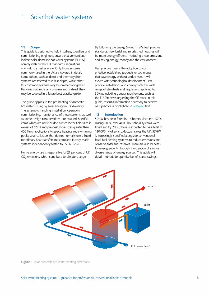
�.3 SDHW systemsIn the UK, there are two common primary system layouts:
Fully-filled Drainback
Air is displaced from the circuit by the transfer fluid present in the collector.
A reservoir of air only allows the transfer liquid to reach the collector under the action of a pump.
Under normal conditions, the transfer fluid in the circuit would always be above atmospheric pressure.
The transfer fluid may occasionally drop below atmospheric pressure.
The system may be open to the atmosphere or sealed. The system may be open to the atmosphere or sealed.
The transfer fluid is normally an antifreeze solution to ensure continued functioning of safety devices in all conditions.
The transfer fluid may be an antifreeze solution to ensure continued functioning of safety devices in all conditions.
Undesirable overnight heat loss is prevented by one-way check valves.
Undesirable thermosyphon circulation is prevented by switching the pump off: this allows drainback of liquid from the collector.
Pipework can undulate provided air can be released at high points and fluid drained at low points.
Pipework must always fall towards the drainback vessel.
Fluid expansion is contained by an expansion vessel with an internal, flexible membrane.
Fluid expansion is contained by a vessel with an air pocket.
Schematic of a typical fully-filled system Schematic of a typical drainback system
Note: Essential safety equipment and other best practice omitted for clarity.
Note: Essential safety equipment and other best practice omitted for clarity.
Numerous variations are possible on these basic designs. However this guide focuses on best practice for the mainstream systems currently fitted in the UK.
Hot water store Hot water storeDrainback
vessel
Pump
PumpCheckvalve
Expansionvessel
Solarcollector
Roof
Solarcollector
Roof
8 Solar water heating systems – guidance for professionals, conventional indirect models
3 Design detail
A successful design will take into account a variety of individual tasks:
Sequence Task3.1 Collectors3.2 Solar primary types3.3 Primary system components3.4 Secondary systems3.5 Pre-heat storage3.6 Auxiliary DHW heating3.7 Combined storage – Twin-coil cylinders3.8 Separate storage – Two stores3.9 Separate storage – Direct DHW heaters3.10 Risk of scalding3.11 Risk of bacteria proliferation3.12 Limescale3.13 Energy conservation 3.14 Controls and measurement
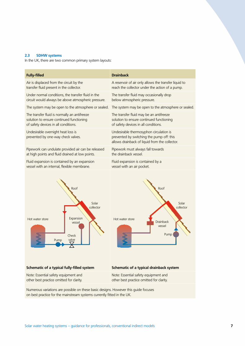
3.1 CollectorsA solar collector absorbs solar irradiation and converts this into thermal energy. The part which receives radiant solar energy is called the absorber: this usually has a translucent cover which allows light in and reduces heat losses from convection. An insulated enclosure provides structural integrity and reduces losses from conduction. Connectors allow fluid from the primary loop to circulate and control heat transmission from the collector into the dwelling. Collectors are either flat or tubular.
The collector is mounted on the outside of the building and is therefore subject to extremes of weather. During high irradiation periods, if there is no heat extraction, an absorber will normally stagnate between 150°C and 300°C. The absorber will then contain super-heated fluid or vapour at a pressure of up to 6 bar (six times atmospheric pressure) depending on the safety limiting devices. A collector of good design should be able to survive these conditions safely and reliably, without specialised maintenance, for over 20 years.
BS EN 12975 sets out procedures to test durability and reliability under extreme conditions, and provides a measure of energy performance. When an EN 12975 test report is published by a manufacturer, the CO2 mitigation potential and safe design of a proposed system can be easily assessed and calculated.
A collector should be tested and independently certified to EN 12975 in respect of durability, reliability and performance.
Performance is measured by EN 12975 by means of a plot of efficiency versus temperature difference (see Figure 5). The test also gives an indication of the variance due to the angle of incidence and the thermal inertia. These results can be used directly in predictive software and other calculations which assess monthly or annual performance.
The amount of energy collected is largely determined by the area and efficiency of a collector, and it is important to be clear whether the gross or net area is being referred to when making comparisons (see box below). Collector efficiency varies according to temperature. Even a collector that is 85 per cent efficient when cold will in most circumstances have an average conversion efficiency of around 60 per cent due to heat losses. Further losses (from transmission, storage and distribution) will reduce
Figure 3 Tubular collector (Photo courtesy of Centre of Alternative Technology)
Figure 4 Flat collector

Solar water heating systems – guidance for professionals, conventional indirect models �
overall system efficiency to below 50 per cent (Figure 8). A reflector can artificially enlarge the aperture area, but it only works effectively in direct sunlight. In addition, the highly polished surfaces can quickly tarnish and fade in humid UK conditions.
3.� Solar primary typesA transfer fluid moves heat from the collector into the dwelling. Because of the high stagnation temperatures in the collector, only specially prepared fluids should be used – and these may differ between systems. These must also resist freezing (or they must be drained away from components where there is a risk of freeze damage). All primary components should be resistant to freeze damage in external and untreated areas.
The chosen transfer fluid in the collector primary circuit should not deposit limescale, sludge, ice or other solids that could restrict circulation or impair the rate of heat transfer.
A closed loop primary system (or indirect circuit) best meets this requirement. It allows heat to move from the collector into a pre-heat store by re-circulating the primary fluid. In normal operation, one pipe (the flow) takes hot fluid from the collector
and the other (the return) will bring cooler fluid back. A heat exchanger is present in an indirect system to ensure that fresh cold water does not circulate into the primary solar collector loop.
A direct system does not have a heat exchanger; the transfer fluid is the same water that is ultimately used at the DHW taps and appliances. This type of circuit does permit fresh water to enter the collector loop with the risk of limescale deposition inside the absorber. Limescale reduces efficiency and in severe cases can block the primary loop. In freezing conditions there is a high risk that ice could form, blocking expansion and safety vents. Compliance with the water regulations can be onerous with respect to preventing damage to rigid components in unheated spaces.
Thermosyphoning is the natural movement of fluid due to the difference in fluid buoyancy at different temperatures. Due to the layout of most UK dwellings, it is rare that thermosyphon circulation can be used instead of a pump. Safety factors, including the adequate control of heat circulation and conservation of stored heat, further restrict its application. The direct connection of a pump to a power source, such as a photovoltaic (PV) module, presents similar safety issues.
Figure 5 Simplified efficiency graph to EN 12975
100
80
60
40
20
0
Global solar irradiance in collector plane (G) = 800W/m2
Efficiency(per cent)
Temperature difference between collector fluid and ambient air
Absorber areaAperture areaGross area
Collector area The physical area of a collector is the gross area; typically the overall size. The area of the absorber within the collector frame is the net area. The aperture area is the unshaded opening that permits or reflects light in. In Figure 5 the absorber area and the aperture area are the same.
A collector complying with EN 12975 may bear a ‘Solar Keymark’. A CE mark may show compliance with certain European Directives (see Appendix 6.4). Other data to be shown includes maximum power, design temperature and design pressure.

10 Solar water heating systems – guidance for professionals, conventional indirect models
The transfer fluid normally contains anti-corrosion inhibitors and antifreeze. An accessible test point is required in the circuit to safely draw off small samples of transfer fluid for inspection during periodic maintenance. The antifreeze must be specifically designed for solar systems and present a low toxicity in the event of a leak. Typical car antifreeze must not be used. Provided annual inspections are carried out, the antifreeze may not need to be replaced in a well-designed system for the whole of its design life.
To allow a collector to receive optimum irradiance, it is best located on the roof to avoid localised shading. In most cases, maximum efficiency and safety of circulation is achieved with a pump under temperature control (see Section 3.4). Closed loop circulation normally uses a pump.
3.3 Primary system componentsSolar primary systems are subject to extreme temperatures far in excess of those encountered under normal household conditions. In the event of a circulation failure during hot weather, stagnation can occur when maximum temperature and pressure are reached. Primary fluid temperatures of over 150°C are commonplace in summer, so all materials in contact with primary system fluids (especially non-metallic components, such as pipe supports, pipe insulation and control cables) should be selected with care and should bear clear, permanent marks indicating suitability. Supporting technical data, normally left on-site, should indicate the full stagnation temperature of the collector.
Many commonplace plumbing materials will quickly fail under these severe conditions, so specialised components are normally required. Non-metallic (elastomeric) materials, fittings and accessories have a history of premature failure: their temperature limits should be confirmed by permanent marking, identification or technical data left on site. Protection against vermin attack should be considered externally and in internal voids.
For safety reasons, non-metallic pipes carrying fluids on solar primary systems should be independently tested to ISO 9808 (BS 7431). In general, materials for solar primary circuits can be specified to ISO/TR 10217 and BS 6700.
External system components should be designed to withstand the collector stagnation temperature, ultra-violet degradation and vermin.
A safety limiter must protect the component in the system with the weakest pressure rating. Components, including the transfer fluid, must be chosen so as to maintain safety in all foreseeable conditions. Ice or limescale formation must not be permitted to obstruct safety devices or routes to safety devices.
All components in a solar primary system must be marked or identifiable in such a way that their design pressure and temperature can be readily determined. A termination from a safety pressure device should be directed into a high temperature receptacle, an internal gully or else issue externally at ground level. High level termination from walls or on roofs could cause injury to people or animals below if the valve were to release scalding water and steam.
A safety device to control the risk of over-pressure in system components should be fitted. The pipe leading to it and the collector should be of rigid and non-deformable construction, without any possibility of restriction or closure by any other fitted component. The termination location should minimise the risk of damage to persons or materials.
During automatic thermostatic control cycles, power failures or a pump breakdown, the circulation in a solar primary system will stop. Simultaneous high solar irradiance can cause the fluid contents within the absorber to vaporise. Inappropriate design can lead to this fluid being expelled under pressure from the system, with the risk of scalding or material damage – in addition, the operator may have to intervene to restore function.
Such situations can lead to a repeated loss of usable energy contribution and of CO2 mitigation. Primary systems can, however, be designed to automatically and safely resume after stagnation. Such systems conform to the principles of overheating protection in EN 12976 and can be termed inherently secure.
A primary system should be designed such that:
There is no release to atmosphere of any high temperature fluid (vapour or liquid) under any operating conditions.
There is auto-resume of normal operation after stagnation without end-user intervention.
•
•

Solar water heating systems – guidance for professionals, conventional indirect models 11
These requirements can be met in a closed (sealed) primary system by a vessel large enough to hold the primary fluid contents of the collector plus the expansion volume of the system (which varies between cold and hot conditions).
Such a system requires a careful choice of equipment and specific installation skills, but has the advantage of allowing reliable, automatic, thermostatic control with minimum risk of overheating or loss of high temperature fluid. The vessels used for containing fluid vary between system types (see Section 2.3) and are described in Figure 6.
3.4 Secondary systemsA secondary system receives energy from a primary system (see Section 3.2). It stores this energy and distributes it to the DHW appliances of the dwelling. The storage method varies greatly depending on: the available water pressure; the existing DHW stores and DHW appliances; the water quality; and the physical space available. In addition, it is essential to provide a sufficient volume of water to accept the solar energy whenever it is available. This will maintain the collector efficiency and predicted carbon dioxide savings. Solar storage is described in the next section. General guidance on hot water services can be found in BS 6700 (soon to be superseded by BS EN 806).
3.5 Pre-heat storageThe pre-heat store is the principal location where energy is delivered from the primary system. This is integrated with any other heat sources situated further ‘downstream’ in the DHW system. These additional heat sources top-up any temperature shortfall from the solar-generated pre-heat water before final distribution as DHW.
The pre-heat storage must be sufficiently sized and matched to the solar primary system to avoid excessive utilisation losses and to reduce the frequency of stagnation, which reduces the life of components. The pre-heat storage is abbreviated as ‘Vs’ and is measured in litres (see also Figure 2).
To work correctly, there must be enough storage dedicated to the solar primary circuit that no other heating source will normally affect its operation. This refers to heat sources intended to contribute to average daily DHW demand (V); it does not mean manually-controlled sources used for occasional boost beyond mean daily DHW demand or automatic sterilisation routines. A suitable pre-heat solar store will maximise the safe displacement of fossil fuel and the most significant variable in a store’s performance is the volume (Vs), which should be sized to household DHW use or the absorber area.
Fully-filled systemThe vessel is not insulated in order to reduce the effect of heat on the flexible rubber membrane. The vessel is not part of the circulatory loop and normally remains cool.
Drainback systemThe vessel is insulated as it is part of the circulatory system and becomes hot.
Figure 6 Schematics of two types of vessel used in SDHW
Pre-chargegas adjustment
Single branchconnection tocircuit
Twoconnectionsin serieswith circuit
Air aboveliquid
Metal shell
Level whenpump is running
Level whenpump is off
Metal shell Internalflexible membrane
1� Solar water heating systems – guidance for professionals, conventional indirect models
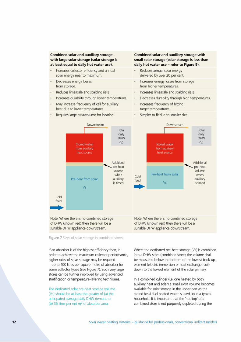
If an absorber is of the highest efficiency then, in order to achieve the maximum collector performance, higher rates of solar storage may be required – up to 100 litres per square metre of absorber for some collector types (see Figure 7). Such very large stores can be further improved by using advanced stratification or temperature-layering techniques.
The dedicated solar pre-heat storage volume (Vs) should be at least the greater of (a) the anticipated average daily DHW demand or (b) 35 litres per net m2 of absorber area.
Where the dedicated pre-heat storage (Vs) is combined into a DHW store (combined store), the volume shall be measured below the bottom of the lowest back-up element (electric immersion or heat exchanger coil) down to the lowest element of the solar primary.
In a combined cylinder (i.e. one heated by both auxiliary heat and solar) a small extra volume becomes available for solar storage in the upper part as the stored fossil fuel heated water is used up in a typical household. It is important that the ‘hot-top’ of a combined store is not purposely depleted during the
Combined solar and auxiliary storage with large solar storage (solar storage is at least equal to daily hot water use).
Combined solar and auxiliary storage with small solar storage (solar storage is less than daily hot water use – refer to Figure �).
Increases collector efficiency and annual solar energy near to maximum.
• Reduces annual solar energy delivered by over 20 per cent.
•
Decreases energy losses from storage.
• Increases energy losses from storage from higher temperatures.
•
Reduces limescale and scalding risks.• Increases limescale and scalding risks.•
Increases durability through lower temperatures.• Decreases durability through high temperatures.•
May increase frequency of call for auxiliary heat due to lower temperatures.
• Increases frequency of hitting target temperatures.
•
Requires large area/volume for locating.• Simpler to fit due to smaller size.•
Note: Where there is no combined storage of DHW (shown red) then there will be a suitable DHW appliance downstream.
Note: Where there is no combined storage of DHW (shown red) then there will be a suitable DHW appliance downstream.
Figure 7 Sizes of solar storage in combined stores
Downstream
Cold feed
Cold feed
Downstream
Stored waterfrom auxiliaryheat source
TotaldailyDHW(V)
TotaldailyDHW(V)
Pre-heat from solar
Vs
Stored waterfrom auxiliaryheat source
Pre-heat from solar
Vs
Additionalpre-heatvolumewhen
auxiliaryis timed
Additionalpre-heatvolumewhen
auxiliaryis timed

Solar water heating systems – guidance for professionals, conventional indirect models 13
day as comfort levels or bacterial-cleansing ability may be reduced. According to CEN/TC 228, where an existing DHW store is modified to accept solar storage or any other heat sources are present, the additional useful solar storage is that indicated in Figure 8. The additional solar volume can be considered additional to the dedicated pre-heat storage volume (Vs).
Type of auxiliary heatAuxiliary storage
accessible for solar storage (per cent)
Permanently switched on Less than 10
Overnight (off-peak) 30
Timed twice daily 30
Emergency or hygiene de-stratification auxiliary heat
70
Figure 8 Table of storage factors
In order to restrain the overall size of the combined store and yet retain the vital solar storage in the lower portion, techniques to reduce the upper auxiliary storage volume have been developed, including the use of high recovery boiler coils.
Where a combined store is used horizontally, there can be up to 40 per cent loss of solar storage compared with one of similar size placed vertically. Where a store has to fit in a small space, the consequence of reducing solar storage is indicated in Figure 9.
Solar storage per litre of daily DHW used
Proportion of solar energy utilised
Vs / V per cent
1.0 or more 100
0.9 98
0.8 95
0.7 92
0.6 89
0.5 86
0.4 82
0.3 or less 77 or less
Figure � Storage parameters
A heat exchanger is normally placed between the collector primary loop and the solar store. Due to the predominately low temperature range of transfer, such heat exchangers need much larger surface areas than conventional exchangers. Their performance is considerably affected by choice of materials and shape. As a general rule, copper-finned exchangers can be designed with a lower surface area than a smooth bore steel type, but in all cases the net heat transfer should be at least 40W/K per m2 of exchanger per net unit area of collector absorber (according to prEN 12977).
The heat exchanger between a solar primary and secondary system should not reduce the maximum collector efficiency by more than 10 per cent under full circulation.
If a solar heat exchanger is placed adjacent to, or intertwined with, another heat exchanger, then unwanted (reverse) heat transfer can occur and the dedicated pre-heat volume will be diminished. A similar problem will occur where an electric immersion element is not sufficiently high enough or a secondary pump acts to circulate hot water downwards through the store.
Ideally, the collector return loop connection is made at the coolest part of the system, possibly adjacent to the store’s cold feed. In a combined store, a physical division between different heat sources (i.e. a clear vertical separation, as shown in Figure 1) should be used in preference to a ‘time-control’ strategy relying purely on electronic devices.
Physical separation offers a more robust method of securing the essential solar pre-heat volume necessary for efficient solar collector performance (see Figure 7).
A solar heat exchanger must act wholly within, and at the lowest point of, the dedicated solar pre-heat volume.
Test method prEN 12977-3 provides a measure of the energy performance of a solar store. This standard allows the CO2 mitigation of a proposed system to be calculated and from this information the most suitable store for a given solar primary system can be selected.
A store for secondary water pre-heated by a solar system should be tested and independently certified to prEN 12977-3 or equivalent.
14 Solar water heating systems – guidance for professionals, conventional indirect models
Adequate labelling of the solar store is essential if correct commissioning, prediction of performance and future maintenance are to be ensured. This should be additional to any other labelling required due to the presence of other heat sources. Solar store labelling should include:
Rating of each internal heat exchanger and description of type.
Maximum operating pressure of all primary heat exchangers.
Stand-by heat loss rate, with allowance for variable solar temperatures.
Thermal stratification is the natural layering of buoyant warmer water over cold. Its effects are desirable in pre-heat storage in order to maintain effective heat transfer from the primary loop. For the same volume, the effect is most pronounced in tall, thin stores with an elevated height width ratio. Stores in horizontal format have poor stratification and therefore are not recommended for solar storage (see previous page).
With careful arrangement of exchange surfaces and choice of materials, the mixing sometimes caused by thermal eddies, cold feed inrush and cylinder wall conduction can be reduced in stores of certain formats. These may use extra vertically stacked coils, tubes or internal separators to encourage the ‘chimney’ effect of buoyant warm water.
Some pump controls can be programmed to delay circulation and increase the primary loop temperature before loading, which will encourage stratification. The thermal stratification of DHW stores should be considered separately from that in solar pre-heat stores. A test method to measure solar store stratification is given in prEN-12977-3.
•
•
•
At least one temperature sensor should be fitted in a dedicated solar store. For a combined store, two are preferable (one for dedicated solar, one for auxiliary). These should make good thermal contact with the stored water and should be insulated against surrounding ambient air temperature. A robust clip or threaded boss should retain the sensor in place and, ideally, the sensor pockets would be immersed into the store.
3.6 Auxiliary DHW heatingAuxiliary heating provides an additional source of reliable heat for both comfort and safety. In part, this is required because of the variable nature of solar irradiation through the day and annually through the seasons. Auxiliary heat sources are fitted downstream of the solar pre-heat storage in order to allow the variable temperature of the pre-heated water to be best controlled (see Figure 2). Another reason to make this separation downstream is to ensure that the auxiliary heat sources do not interfere with heat transfer from the primary circuit. A collector works most efficiently at lower temperatures, hence a separation will ensure that auxiliary heat does not prevent solar primary heat transfer and, in addition, that auxiliary heat is not accidentally circulated to the collector.
An automatic gas/oil/electric auxiliary heat source downstream of a solar pre-heat store should preferably be controlled with a temperature interlock. In particular, when the stored, solar heated water has reached the intended target temperature, then the auxiliary heat source should automatically switch off and not be called to add extra heat above the target temperature.
Manually-fed auxiliary heat sources (e.g. log stoves with back boilers), have to be manually controlled by the user, making best use of the system’s temperature and circulation indicators.
Solar water heating systems – guidance for professionals, conventional indirect models 15
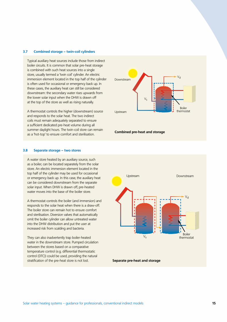
Typical auxiliary heat sources include those from indirect boiler circuits. It is common that solar pre-heat storage is combined with such heat sources into a single store, usually termed a ‘twin coil’ cylinder. An electric immersion element located in the top half of the cylinder is often used for occasional or emergency back up. In these cases, the auxiliary heat can still be considered downstream: the secondary water rises upwards from the lower solar input when the DHW is drawn off at the top of the store as well as rising naturally.
A thermostat controls the higher (downstream) source and responds to the solar heat. The two indirect coils must remain adequately separated to ensure a sufficient dedicated pre-heat volume during all summer daylight hours. The twin-coil store can remain as a ‘hot-top’ to ensure comfort and sterilisation.
3.7 Combined storage – twin-coil cylinders
Downstream
Upstream
Vs
Vd
Boilerthermostat
Combined pre-heat and storage
DownstreamUpstream
Vs
Vd
Boilerthermostat
Separate pre-heat and storage
3.8 Separate storage – two stores
A water store heated by an auxiliary source, such as a boiler, can be located separately from the solar store. An electric immersion element located in the top half of the cylinder may be used for occasional or emergency back up. In this case, the auxiliary heat can be considered downstream from the separate solar input. When DHW is drawn off, pre-heated water moves into the base of the boiler store.
A thermostat controls the boiler (and immersion) and responds to the solar heat when there is a draw-off. The boiler store can remain hot to ensure comfort and sterilisation. Diversion valves that automatically omit the boiler cylinder can allow untreated water into the DHW distribution and put the user at increased risk from scalding and bacteria.
They can also inadvertently trap boiler-heated water in the downstream store. Pumped circulation between the stores based on a comparative temperature control (e.g. differential thermostatic control (DTC)) could be used, providing the natural stratification of the pre-heat store is not lost.
16 Solar water heating systems – guidance for professionals, conventional indirect models
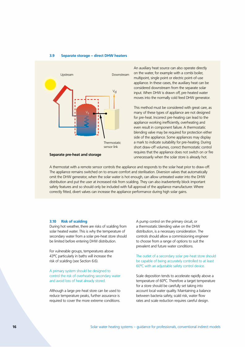
3.� Separate storage – direct DHW heaters
A pump control on the primary circuit, or a thermostatic blending valve on the DHW distribution, is a necessary consideration. The controls should allow a commissioning engineer to choose from a range of options to suit the prevalent and future water conditions.
The outlet of a secondary solar pre-heat store should be capable of being accurately controlled to at least 60ºC with an adjustable safety control device.
Scale deposition tends to accelerate rapidly above a temperature of 60ºC. Therefore a target temperature for a store should be carefully set taking into account local water quality. Maintaining a balance between bacteria safety, scald risk, water flow rates and scale reduction requires careful design.
3.10 Risk of scaldingDuring hot weather, there are risks of scalding from solar heated water. This is why the temperature of secondary water from a solar pre-heat store should be limited before entering DHW distribution.
For vulnerable groups, temperatures above 43ºC particularly in baths will increase the risk of scalding (see Section 6.6).
A primary system should be designed to control the risk of overheating secondary water and avoid loss of heat already stored.
Although a large pre-heat store can be used to reduce temperature peaks, further assurance is required to cover the more extreme conditions.
An auxiliary heat source can also operate directly on the water, for example with a combi boiler, multipoint, single point or electric point-of-use appliance. In these cases, the auxiliary heat can be considered downstream from the separate solar input. When DHW is drawn off, pre-heated water moves into the normally cold feed DHW generator.
This method must be considered with great care, as many of these types of appliance are not designed for pre-heat. Incorrect pre-heating can lead to the appliance working inefficiently, overheating and even result in component failure. A thermostatic blending valve may be required for protection either side of the appliance. Some appliances may display a mark to indicate suitability for pre-heating. During short draw-off volumes, correct thermostatic control requires that the appliance does not switch on or fire unnecessarily when the solar store is already hot.
A thermostat with a remote sensor controls the appliance and responds to the solar heat prior to draw-off. The appliance remains switched on to ensure comfort and sterilisation. Diversion valves that automatically omit the DHW generator, when the solar water is hot enough, can allow untreated water into the DHW distribution and put the user at increased risk from scalding. They can also inadvertently block important safety features and so should only be included with full approval of the appliance manufacturer. Where correctly fitted, divert valves can increase the appliance performance during high solar gains.
DownstreamUpstream
Vd
Thermostaticsensor link
Vs
Separate pre-heat and storage

Solar water heating systems – guidance for professionals, conventional indirect models 17
3.11 Risk of bacteria proliferationThe solar pre-heat volume will vary through the year, in temperatures ranging from as low as 5ºC in winter up to possibly 85ºC in summer. In this respect, pre-heated water should not be considered as fully treated for DHW use and should not enter the household distribution until it has been further conditioned for comfort and safety. There is an increased risk of bacteria growth at temperatures between 20ºC to 46ºC during prolonged periods without DHW draw-off. Special attention should be given to situations where cold water originates from unclean water cisterns (without lids) or where there are porous, suspicious or unknown fittings in contact with the water.The risks can be minimised by:
Reducing pre-heated storage to below twice the average daily hot water use.
Using indirect primary circuits.
Replacing old, poorly insulated DHW stores.
Using electronic primary pump controls with programming targeted to achieve 60ºC storage.
Reducing long lengths of uninsulated secondary pipework.
Irrespective of the above, reliable sterilisation is best achieved by ensuring pre-heated water passes through to another reliable heat source capable of sterilisation of unwanted bacteria. It should be noted that legionella bacteria can be expected to be killed within seconds at 60ºC.
All solar pre-heated secondary water should be designed to pass through an auxiliary heat source capable of heating to least 60ºC (at all foreseeable flow rates) before DHW distribution .
It should be noted that the use of de-stratifying secondary pumps or an occasional back-up heat source within the pre-heat store could drastically reduce the solar performance and effectively de-rate the dedicated pre-heat store. To optimise solar efficiency, secondary circulation distribution is best implemented only in the DHW store. However, where a high risk of bacterial proliferation exists, the solar pre-heat store can be designed to be regularly sterilised, ideally at the end of the day to give the best chance for this to be achieved by solar. Such sterilisation should be accurately controlled by time and temperature in order to restore solar storage promptly.
•
•
•
•
•
3.1� Risk of limescaleThe higher temperatures experienced in solar stores can mean that limescale becomes a significant problem. This can eventually reduce the performance and efficiency of the solar system. The problem varies from site to site and a skilled assessment is required before attempting to minimise the risk.
When considering the use of products that are claimed to reduce limescale, thought should be given to the effects of varying future water quality, unexpected user intervention and any parasitic or standing electrical losses that may be required to operate such devices.
In solar stores, the possibility of limescale forming should be considered and controls implemented to ensure that future performance is not significantly affected.
Direct solar primary systems are particularly prone to limescale within the absorber. An indirect circuit should always be considered as the first step to reducing the risk of limescale inside the absorber.
Where the cold water supply is expected to be above 100mg/l calcium carbonate average equivalent, written procedures for monitoring and cleaning areas likely to be affected by limescale should be given to the end-user. In particular, the likely risk of long term limescale formation in the pre-heat store and on the heat exchange surfaces should be considered.
Techniques to reduce heat exchanger temperatures have beneficial results in high limescale areas and can be more robust than additional devices such as water softeners. In severe cases, pre-heat solar storage can be limited to 60ºC through temperature control of the primary circulation or by increasing the size of heat exchanger.
Similar effects can be realised by increasing the fluid content of the collector primary loop or increasing the primary circulation rate.
In potentially severe cases of limescale formation, the solar pre-heat exchanger should be made accessible for an annual cleaning procedure described in documentation left on site. Alternatively, the secondary solar pre-heat store should be capable of being accurately controlled to below 60ºC.

18 Solar water heating systems – guidance for professionals, conventional indirect models
3.13 Energy conservationWithin the insulated building envelope, solar energy contributes to the controlled interior environment of the dwelling. As a rule, thermal solar energy is a useful, low carbon displacement for fossil fuels. Where solar thermal energy can be used immediately, it can be considered to have a high usability factor.
However, where long storage times are required then the usability factor is low. Normally, solar thermal energy is stored for at least some time until required. The use of insulation and efficient methods of transferring heat will reduce losses, increase the displacement of fossil fuels and improve comfort.
SDHW primary systems contain components that work at temperatures typically from below zero to more than 150°C. Peaks can occur within just a few hours. According to DTI Report SP 300275-3, solar stores that are poorly insulated can account for losses of over 15 per cent (of the useful energy produced annually) in addition to increasing the overheating risk for parts of the dwelling during summer.
Although a solar store tends to lose heat more slowly during low irradiation periods (due to lower storage temperatures), high losses can still occur, particularly in summer. For existing best practice for DHW storage see CHeSS (HR6 note 9).
The insulation of a solar pre-heat store should be at least equivalent to current best practice for conventional DHW stores.
Pipes transferring solar primary fluids occasionally carry temperatures in excess of 150ºC. This is much higher than conventional DHW or boiler primary pipes and, if un-insulated, pipes can lose over 10 per cent of the total annual useful solar energy according to BS 5422.
Pipes that are not well insulated can unnecessarily add to the overheating of spaces during summer and present a risk of contact burns. Heat loss can also occur through air infiltration at pipe/roof penetrations and unwanted thermosyphoning of fluid in pipes from warm ambient air.
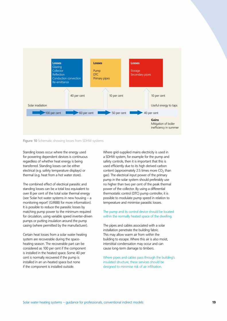
Existing water and building regulations already set insulation levels for pipes in certain circumstances and prEN 12828 or BS 5422 provides further guidance. However, best practice would extend these levels to all internal solar primary pipes. Reducing pipe diameters can reduce heat loss from pipes but this should be done with care, to avoid increasing electrical parasitic pump losses due to increased pumping (see Figure 10).
All pipes of a solar primary system should be insulated to a conductivity no greater than 0.040W/mK and the thickness should be at least one and a half times the pipe diameter – or an equivalent heat loss measured at 50ºC.
It should be noted that pipe insulation must withstand the full stagnation temperature from the collector and be proof against vermin attack, externally and in voids. Externally, such insulation should be judged for its ability to withstand weather, ultra-violet degradation and vermin.
A stagnation temperature of 150ºC should be regarded as the minimum although it could well be higher, depending on the collector.
Parasitic losses occur where energy is simultaneously used for other devices during the operation of the circuit. An example is a pump circulating the primary fluid from the collector. Parasitic losses are generally from electrically powered devices.
Solar water heating systems – guidance for professionals, conventional indirect models 1�
Standing losses occur where the energy used for powering dependent devices is continuous regardless of whether heat energy is being transferred. Standing losses can be either electrical (e.g. safety temperature displays) or thermal (e.g. heat from a hot water store).
The combined effect of electrical parasitic and standing losses can be a total loss equivalent to over 8 per cent of the total solar thermal energy (see ‘Solar hot water systems in new housing – a monitoring report’ (GIR88) for more information). It is possible to reduce the parasitic losses by matching pump power to the minimum required for circulation, using variable speed inverter-driven pumps or putting insulation around the pump casing (where permitted by the manufacturer).
Certain heat losses from a solar water heating system are recoverable during the space-heating season. The recoverable part can be considered as 100 per cent if the component is installed in the heated space. Some 40 per cent is normally recovered if the pump is installed in an un-heated space but none if the component is installed outside.
Where grid-supplied mains electricity is used in a SDHW system, for example for the pump and safety controls, then it is important that this is used efficiently due to its high derived carbon content (approximately 2.5 times more CO2 than gas). The electrical input power of the primary pump in the solar system should preferably use no higher than two per cent of the peak thermal power of the collector. By using a differential thermostatic control (DTC) pump controller, it is possible to modulate pump speed in relation to temperature and minimise parasitic losses.
The pump and its control device should be located within the normally heated space of the dwelling.
The pipes and cables associated with a solar installation penetrate the building fabric. This may allow warm air from within the building to escape. Where this air is also moist, interstitial condensation may occur and can cause long-term damage to timbers.
Where pipes and cables pass through the building’s insulated structure, these services should be designed to minimise risk of air infiltration.
Solar irradiation
40 per cent 10 per cent 10 per cent
Useful energy to taps
GainsMitigation of boiler inefficiency in summer
100 per cent 60 per cent 50 per cent 40 per cent
LossesGlazingCollectorReflectionConduction convection Re-emittance
Losses
PumpDTCPrimary pipes
Losses
StorageSecondary pipes
Figure 10 Schematic showing losses from SDHW systems

�0 Solar water heating systems – guidance for professionals, conventional indirect models
3.14 Controls and measurementControls are needed to conserve heat, retain commissioned settings and maintain safety. They may also provide relevant measurement or monitoring information so that a user can properly operate the system or report errors. Controls may be electrical or mechanical and their correct location and commissioning are vital to long term performance.
Where a control is concerned with safety, it should be readily accessible and verifiable in operation during commissioning and maintenance.
A solar collector can waste useful heat from inside the dwelling if poorly controlled. During the night, heat in warm water located near the solar circuit can easily rise via the primary pipes to a solar collector by natural convection (thermosyphon), forming a circulation loop within the pipes which is capable of completely cooling a solar pre-heat store overnight. Inadvertent triggering of a temperature control sensor in the solar collector can then switch on a pump, exacerbating the situation.
This circulation can be caused by:
Warm ambient air heating the fluid in the pipes and causing thermosyphoning to the cooler collector.
DHW heated from auxiliary fuel sources entering the solar primary.
Solar heat, previously collected, re-entering the pre-heat store.
Cold-feed for the store entering the primary.
•
•
•
•
On cloudless nights, the temperature of an absorber can fall below the ambient temperature due to the black-body radiation phenomenon, resulting in unintentional freezing of the absorber surface. A combination of methods is required to control such losses. These can be combined with circulation controls to improve collector and heat exchanger performance.
A means of preventing reverse circulation should be provided, in both flow and return primary pipes, to avoid loss of stored heat.
For fully flooded systems, anti-reverse circulation devices normally include a spring-loaded one-way check valve located in both the flow and return pipes. These should be carefully specified and positioned with consideration to expected stagnation temperatures – hence generally located away from the collector. These valves may require a bypass or drain-point to allow complete flushing/draining during installation and periodic maintenance.
Drainback systems normally have no fluid remaining in the primary circuit once the pump has stopped. They must not be fitted with check valves in the circuit, but will instead rely on a downward drop in the pipes to a vessel.
A temperature ‘interlock’ should be provided to ensure that the solar system cannot normally transfer useful heat outside the insulated building envelope.
DTC
Pump interlock by comparingtwo temperature sensors A & B
Sensor A locatedtowards flow
Third sensor for safety information
Pump
Return
Flow
Collector
Physical separation between solar and auxiliary heat sources
Sensor B located low in solar storage
Auxiliaryheat store
Figure 11 Preventing loss of stored heat

Solar water heating systems – guidance for professionals, conventional indirect models �1
There should be no possibility for the collector to remove heat from another heat source. Essentially, under normal conditions the pump must not circulate heat if the collector is cooler than the solar storage. This is best prevented by using at least two temperature sensors, one fitted into the absorber and the other into the solar store. These must operate in conjunction with each other to permit pump circulation only when useful net heat can be gained. This forms part of an ‘interlock’ between the collector loop and the pump.
This control interlock should be combined with a further means of preventing storage heat from being lost up to the collector: this should be a physical separation between auxiliary heat sources (downstream) and the solar circuit.
It is vital that the primary circulation is temperature-controlled if the system is to operate optimally and the displacement of fossil-based heat is to be maximised. By comparing the temperature in the absorber with that in the solar storage heat exchanger the heat transfer process can be optimised; it will also reduce wear and tear on components as well as controlling the absorber at its most efficient i.e. when cool.
The DTC, allows precise adjustments of pump switching on/off points and provides a readout to aid commissioning and fault detection. A simple, single thermostat is not suitable for controlling SDHW since this does not compare the temperatures of the collector and its store.
Sensors for solar system controls, such as a DTC, have to display good accuracy across a wide measurement range whilst maintaining a good thermal contact with the fluid being measured. They should be insulated against change in ambient temperatures and firmly clamped to prevent accidental displacement.
They should also be responsive to rapid changes, and should ideally be placed in purpose-made pockets immersed in the fluid. A coating of instrument grease can be used to withstand ingress of moisture that can cause a sensor to fail.
Sensors should be expected to maintain an accuracy of ± 1.0ºC across the system’s normal operating range and use a display method with a resolution equal to or better than 1.0ºC.
Figure 1� Differential thermostat
The SDHW primary circuit should be controlled by a temperature-sensitive device accurately measuring the difference in temperature between the absorber and the pre-heat storage or heat exchanger.
The differential is the difference between switching points or thresholds. This is adjusted for an individual installation according to the heat loss of the transfer circuit and heat exchanger configuration. A long distance between a collector and store would require a higher differential than a short run.
The hysteresis is the difference in switching variance around a given point: this can differ according to the direction of movement of temperature (i.e. rising or falling around the switching point). It can be adjusted to avoid unnecessary short cycling or hunting of a pump. A typical differential would be between 5ºC and 10ºC, while the hysteresis would be between 2ºC and 5ºC.
Where a comparative temperature-sensitive device is fitted to a solar primary system, the adjustable values of differential and Hysteresis should be provided.
An additional sensor for irradiation levels is sometimes combined with the two DTC temperature sensors where, for example, there is unfavourable shading across part of the collector. Advanced DTCs use temperature-linked speed control of the circulating pump to maintain higher efficiency heat transfer.
Figure 13 Differential thermostat

�� Solar water heating systems – guidance for professionals, conventional indirect models
During commissioning and periodic maintenance, it is necessary to check the circulation rate of the solar primary circuit fluid in order to confirm that sufficient heat extraction will occur under maximum irradiation.
It is also necessary to check that unwanted air is removed from pipework prior to checking fluid levels. As these checks may take place when available solar irradiation does not create enough circulation (e.g. when cloudy or at night), a suitable method of providing circulation should be available at any time.
A solar primary system should include a manual override to engage circulation for commissioning in all weather conditions, plus a means of accurately indicating primary circulation rate.
For the end-user and the commissioning engineer, it is important to pre-empt any potential loss of performance and to be able to monitor key system functions such as absorber and pre-heat water temperatures. This can be achieved using digital thermometers typically found with a DTC.
A solar system should have the capability to provide a permanent, durable and accurate readout of the temperatures of the absorber, the solar secondary water pre-heat store and the secondary water DHW store.
As there is a significant risk of scalding or over-pressure, a SDHW system must be capable of hydraulic and electrical isolation from any
pump and the pre-heat storage, to allow for periodic maintenance. The isolation mechanism, such as ball or gate valves, must not be able to accidentally isolate the collector from a route to safety devices. In particular, no valve must be placed so as to isolate a safety pressure release valve or expansion/drainback vessel.
A solar primary system should include a clear and safe means of isolating a collector from the pre-heat store.
The level of transmission fluid is a vital early sign of problems such as leaks, unexpected safety discharge or excessive evaporation. A pressure gauge, level mark or test-point in a primary vessel – or a digital diagnostic error readout – is required to identify any loss of pressure in the primary circuit.
A solar primary system should include an indicator of primary circuit transmission fluid levels.
Indicators of correct system functioning are essential to pre-empt reductions in efficiency and potential safety issues. Faults in well-designed SDHW systems often remain unnoticed since other heat sources will automatically compensate. A way of automatically checking errors or implausible values, combined with a clear warning system for malfunctions, should be provided.
A solar primary system should include an automatic warning device to indicate a critical malfunction.
These checks can be based on temperature values pre-selected by a competent commissioning engineer and programmed into a differential pump controller or similar device. Pressure or circulation rates (where relevant) could also be considered as values that might trigger an error indicator.
The indicator should enable a rapid diagnosis of the error and draw the user’s attention to the need for action. Simple counters of time, volume, power or energy alone cannot be considered sufficient warning of a malfunction. The warning itself should either be audible or a flashing light in a frequently occupied location, such as adjacent to the pre-heat store.
Figure 14 Differential thermostat
Solar water heating systems – guidance for professionals, conventional indirect models �3
4 Installation and commissioning
Key installation tasks:
Site survey – technical.
Selection of tools.
Initial testing.
Commissioning.
4.1 Installation tasks: site survey – technicalBefore an accurate quotation for the installation of a SDHW system can be determined, both a risk assessment and a site survey are needed. In the case of dwellings yet to be built, however, there will be pressure to provide a quotation before any on-site risk
•
•
•
•
assessment is possible. In this case, a quotation should indicate which control methods are assumed to be in place either by third parties or inclusive of the quote.
A provision for legal compliance with unanticipated measures would allow a responsible contractor to make suitable and fair comparisons.
The procedure for technical surveys will be different for existing dwellings and new build dwellings. In either case, a standard template could be used to ensure all relevant parameters are noted. The following sub-headings offer such a template.
Technical site survey tasks
a. ShadingTo maximise the direct sunlight striking the collector there should be no shading. In predominantly shaded locations, 50 per cent of the total solar irradiation can be expected to be lost (although the effect is lessened where the collector is vertical). Partial shading, such as shadows of trees, chimneys, higher buildings, etc. can also have adverse effects with localised overheating of the fluid in a collector – or a loss of heat transfer if the sensors are shaded.
Where shading is unavoidable, a shadow greater than 10 per cent of the collector area passing completely across the collector in less than an hour between May and October can be considered acceptable – this providing a full exploration of other collector sites has been examined and an allowance is made in performance predictions. However, if the shadowing lasts in excess of two hours, the customer should be informed in writing – prior to commencing work – that the suggested site is ‘significantly shaded’ and that an ‘oversized’ collector is recommended, at least 20 per cent greater in absorber area than in an unshaded location.
Consideration should be given to a controller capable of switching on the pump for a fixed, limited period once every 30 minutes, subject to temperature control. This can overcome unfavourable sensor positions during shading. Remember that the track of the sun will vary daily from the horizon, peaking to a zenith at midday GMT. In addition, the angle of the zenith will alter significantly from winter solstice to summer. Allowance for the future growth of nearby trees should be considered. See appendix for typical UK irradiation levels.
New build: Shading can be complex to model, although many design software packages now allow shading to be readily calculated. Ideally, the design would ensure a layout and orientation that minimises shading risks and would normally avoid shading that required oversizing. Dedicated commercial software packages for SDHW designers are available. A simple manual method uses graph paper to represent the horizon from east to west with objects plotted in size pro-rata to their distance from the collector position. The remaining area of sky shown on the graph paper gives an indication of direct irradiation.
Existing: A site visit is a prerequisite for assessing shading. A compass and a transparent sheet indicating the tracks of the sun seasonally and daily allow a thorough examination even in cloudy conditions. Every effort should be made to take the shading survey at the collector position, in order to avoid parallax errors arising from estimates made on the ground or at upper windows. Anecdotal comments from occupiers regarding the roof shading should be taken with caution and should be corroborated.
�4 Solar water heating systems – guidance for professionals, conventional indirect models
Technical site survey tasks
b. Collector fixing surface, pitch and orientationThe collector fixing surface can be a pitched roof, flat roof, vertical wall, balustrade or ground mount. Many UK roofs provide close to the optimum pitch, and with a reasonable leeway from south-east to south-west, losses of only 10 per cent of the annual energy yield are typical. This can be accommodated by collector ‘oversizing’; alternatively , a loss of performance can be declared to the user.
Where an excess of 10 per cent less than optimum is predicted i.e. approaching east, west or on steep pitches, the customer should be informed in writing prior to commencing work that the suggested site is ‘significantly less than optimum‘ and that an ‘oversized’ collector is recommended of at least 20 per cent greater absorber area.
In the case of an unfavourable pitch or orientation, collectors are available where the absorber can be rotated within the format of the collector glazing. This is frequently possible with glass tube formats where cylindrical absorber shapes add some advantage. Adjacent tubes should not overshadow each other and typically a maximum rotational gain of 20 degrees is available. The alternative of unequal spacer blocks, or additional frames on pitched roofs, is rarely cost effective.
For flat roofs or ground-mounted systems, a metallic frame can be used to achieve optimum positions; however structural loading should be carefully considered. The use of multi-position collector arrays can be considered where available locations are too small or unfavourable i.e. east/west pitches, although this would require separate and independent circulation controls to avoid unwanted loss of heat through the colder aspect.
Where a choice of pitch is available, consideration should be given to the build-up of dust on the collector surfaces. A nominal 5 per cent loss of energy yield is expected in all conditions without cleaning: however this will increase at pitches of less than 20 degrees. In areas where high build-up is expected i.e. from sea salt, high density traffic or tree sap, the problem will be exacerbated with collectors set at a low pitch.
New build: The available pitch and orientation of collector locations can usually be derived from typical scale drawings. It may still be possible to design the building to optimise SDHW yield i.e. pitched and between south-east and south-west. Rooms-in-roofs can be constructed with purpose-built service routes from the solar collecting surface to the solar storage location. The use of pre-insulated and unjointed flexible metal pipe can be an aid in difficult locations.
Existing: A site visit using a compass and protractor will establish the best locations. Photographs accompanied by scale drawings can also be used.
Solar water heating systems – guidance for professionals, conventional indirect models �5
Technical site survey tasks
c. Collector fixing area, structural loading and roof coveringsA key question concerns whether the solar collector will be located within or above the fixing surface. On a pitched tiled roof, for example, tiles can be removed and the collector set into the roof line, much like a typical skylight. Depending on the roof substructure, it may even be possible to achieve a flush finish not unlike patent glazing. The choice of ‘in-roof’ or ‘above-roof’ will greatly influence the choice of glazing and collector design since glass tube collectors are generally unsuitable for in-roof applications. Care should be taken that the flashing provided with a collector is compatible with localised roof coverings. In-roof applications invariably require hydraulic and sensor connections to the rear of the collector. Whilst this improves aesthetics, reduces heat loss and minimises vermin attack, there can be a downside where access to the underside is restricted (particularly with a room-in-a-roof or vaulted ceiling immediately below).
In above-roof installations, the combined structural loadings of wind and snow can create component loading varying from +2kN through to suction lift of -1kN. This compares to a static loading due to traditional roof coverings of a nominal +0.03kN/m2. It is vital that the combined dynamic loadings of wind and snow are not channelled onto a fragile roof covering. Further considerations include allowance for thermal expansion, differential negative lifting on adjoining components, sufficient (over)lap of roof components, and the ability of the roof structures (i.e. rafters, purlins, trusses) to withstand the loadings.
For a pitched roof, a SDHW collector will require at least four mounting points, with loading taken through, and not onto, the roof covering – either to the rafters or via additional timber bearers using metallic brackets. Traditional timber battens or lath are insufficient to withstand the loading and are vulnerable to long term corrosion.
Prior consideration should also be given to the preferred route for hydraulic and control connections which are likely to require separate weather sealing. In all situations, care should be taken with materials adjacent to fluid-carrying components from the solar system, as these can be at full stagnation temperature (typically in excess of 150ºC).
With a flat roof or ground-mounted system, options include the use of ballast weight or fixing into the mounting surfaces. These may also be used in combination; however great care is required to not overload a sub-structure. A collector can be mounted horizontally in order to avoid excessive wind loadings on the rear of exposed A-frames. Some collectors allow the absorber to be internally rotated to a more efficient angle whilst appearing flat from a distance.
The following roof coverings require particular care in the choice of fixing method. A competent roofer and structural engineer may be required:
Asbestos cement.Built-up felt, supported by wood-wool boards or insulation.Profiled metal supported on metal rafters.Sheet metal (lead, copper, zinc).Conservatory or greenhouse patent glazing.Wooden shingles.Single ply membrane.Thatch.
New build: An ideal location for a solar collecting surface would have a readily removable roof covering (e.g. tiles) for simple structural and pipe/cable access. A clearance gap of no less than two metres to each side of the intended collector position would give suitable working space during installation and permit ease of future maintenance. Consideration of interstitial condensation may be required where humid air is expected to rise towards the pipe entry location from the collector. Where a future solar collector is planned, purpose-made structural mounting points can be provided in advance, especially where the roof covering is not likely to be easy to remove.
Existing: A site visit is invaluable in anticipating existing damage to roof coverings and sub-structure. Where the roof structure has warped over time, difficulties can be experienced in integrating a rigid collector in-roof.
••••••••
�6 Solar water heating systems – guidance for professionals, conventional indirect models
Technical site survey tasks
d. Access to collector locationAccess to the collector location will be required during installation, at future inspections and for maintenance. Typical obstacles include house-width conservatories, power/phone lines, porches, dormers, etc. since safe access methods can be obstructed both at low level or high. The requirement for cleaning can normally be expected to be a low priority at collector pitches of greater than 20 degrees, but should be considered in exceptional conditions. Availability of skylights of sufficient size can simplify future inspections.
Critical solar system components such as pressure safety valves should not be located in inaccessible locations, particularly if the maintenance regime requires these to be inspected.
Other workers who may visit the roof in the future could also be considered i.e. repairs to the roof, TV aerials, and chimney sweeping. Purpose built, non-corrosive steps are commercially available and are designed to provide permanent access on to roof pitch. An alternative, especially for flat roofs, is a cable fastening line for personal harnesses.
New build: Where thick layers of ceiling insulation are expected in roof voids behind the collector location, a walkway can be constructed above the insulation.
Existing: A site visit is required in order to inspect roof voids, the roof condition and clearances for equipment. Externally, the terrain should be checked for stability as well as above for loose roof tiles and overhead cables, etc. Heights of over two storeys should be approached with particular caution.
e. Auxiliary DHW heat sourcesSolar water heating is almost exclusively used to pre-heat DHW and not for space heating. In the UK, additional energy sources are necessary to make up any shortfall that the solar system cannot provide. Such appliances should be carefully considered as some are difficult, or even dangerous, to integrate with solar pre-heating and its (normally) cold supply.
Many DHW appliances require specialist knowledge and inspection before their suitability for solar pre-heating can be determined.
Normally the best whole system performance is achieved by complete replacement of existing DHW heat sources to ensure correct integration. This is the usual choice where the existing DHW is provided from a stored water arrangement. This also has the advantage that best practice for DHW provision can be achieved at the same time. Where the DHW source is a water store that is integrated with another device (such as a combi boiler) or fully instantaneous (such as an electric shower), then it is more common to design a system which retains these appliances.
New build: There is a range of ‘solar-ready’ DHW generators that can be installed in new dwellings independently of a solar primary system. These may include twin-coil stores that combine pre-heat and DHW into one unit; the lower solar coil is either left unconnected (as with an electric based store) or it is temporarily connected in series with the top boiler coil with the advantage of a rapid re-heat. However it is more common to fit a coherent and complete functional solar system with DHW generator simultaneously.
Existing: It is essential to confirm, by on-site test, that existing DHW generators are capable of achieving 60ºC at all foreseeable rates of secondary flow. Using a thermometer and weir gauge, the rate of various DHW flows can be measured against temperature at the outlets to establish the ability to sterilise to 60ºC.
Solar water heating systems – guidance for professionals, conventional indirect models �7
Technical site survey tasks
f. Pre-heat storage locationsFor most dwellings, the notional extra physical space required for pre-heat storage is equivalent to the number of occupants multiplied by at least 0.05m3. This includes space for appropriate insulation and pipe connections. However, further space should be allowed for primary system controls and insulated pipes. Where a twin-coil store is used, the DHW store size is combined with the pre-heat store into one unit; this requires extra space of approximately 2.0m by 1.0m by 0.8m.
The solar pre-heat store must be located where it can readily connect with the solar collecting surface via insulated primary pipes and sensor cables. It should be within the normally heated area of the dwelling.
Generally, it is necessary to have an accessible mains electric power supply in the solar store location to allow the fitting of accurate temperature indicators. In addition, the store needs to be protected from frost. The anticipated weight of a pre-heat store is at least 60kg multiplied by the number of occupants. Accessibility for maintenance should also be considered.
New build: Pre-heat storage locations can easily be designed in a dwelling at its planning stage.
Existing: An on-site survey will be needed to establish if an existing airing cupboard is suitable. Particular care should be taken with floor supports. Unheated voids such as roofs should be carefully checked for future access, floor strength and frost protection.
g. Secondary water pressureThe intended DHW pressure and type of cold feed must be determined early in the design process as certain choices greatly influence the formats of pre-heat storage and DHW generators. In particular, a choice between low pressure (cistern-fed) or mains pressure should be made early. The peak flow-rates of showers and the potential effects of thermostatic mixing valves need to be taken into account. Private water supplies require extra care, in the light of potential summer droughts and intermittent loss of supplies. The integration of solar heating into a dwelling should not unduly impair the secondary water pressure.
New build: Secondary water pressure can be determined for a dwelling at its planning stage.
Existing: A site inspection and measurement of dynamic water pressure will be needed. Specialised tools may be required such as a weir gauge, pressure gauge, stopwatch and measuring jug. By examining the water pressure at one tap within the dwelling while using water from another, it is possible to compare the time to fill a given volume (this gives the flow rate) with the pressure maintained elsewhere in the house.
h. Water qualityWhen incoming cold water is heated, it can produce limescale (due to water hardness). In some areas this may result in a build-up of a hard crust inside hot water stores causing a gradual decrease in the storage, circulation and heat exchange efficiency. Unwanted bacteria can grow in all cold and hot water systems, particularly under tepid temperature conditions with porous materials. The acidity, particularly of private water supplies in upland areas, can aggressively dissolve certain metals. Water quality must be assessed for each site before selecting secondary heating equipment.
New build: Water hardness can be ascertained from maps or from utility companies. Water quality reports based on postcodes are also available. Samples from private supplies will need to be analysed at a laboratory.
Existing: A site visit is required and this is best done by a suitably informed and trained person. The inspection will cover the cold water supply, secondary storage, distribution and appliances. Bacterial risk assessments are best recorded and summarised into low, medium and high risks according to the age of equipment, length of pipe runs, and the ability of auxiliary heat sources to achieve sterilisation at high flow rates.
�8 Solar water heating systems – guidance for professionals, conventional indirect models
Technical site survey tasks
i. Occupant’s DHW regime The way DHW is used greatly affects the solar contribution, no matter what level of equipment is installed. Is the household likely to have a morning peak, evening peak or continuous all day demand? Will there be significant vacant periods i.e. holidays or during relocation? Continuous, even demands require less pre-heat storage, whereas often absent households require over-sized storage. High DHW use per person for example, with power showers or increased laundry use, can make best use of proportionally larger solar collectors. Certain hot water appliances may not accept pre-heated water e.g. washing machines or dishwashers. These are best eliminated from design calculations. A solar system can be designed for a high annual solar fraction or high usability factor (best value). Clients are best consulted and the results recorded.
The DHW usage pattern of a household should be anticipated before selecting secondary heating equipment.
New build: The intended occupancy and their DHW use can be derived from discussion with clients and use of standard references. Where unknown, DHW use at 50ºC per day can be assumed as (38 + 25N) litres per day where N is the number of occupants.
Existing: A site visit to inspect DHW appliances and a discussion with occupants would establish the intended DHW usage pattern.
4.� Installation tasks: Selecting specialist tools
AccessCurrent HSE recommendations require specialised access equipment, including eaves-level platforms, steel scaffold or towers, cranes or hoists.
Seed pumpsThese are special high-flow pumps designed to rapidly fill solar primary systems and remove air or steam locks.
Hand pumpsFor injecting extra antifreeze initially or during maintenance.
RefractrometersFor sampling antifreeze concentrations (alternatively use hydrometers).
pH testers (litmus paper)These are usually coloured impregnated strips which can identify loss of corrosion protection.
High temperature brazingThis is used where soft solder joints are unsuitable at stagnation temperatures.
CoversThese are to stop irradiation reaching the absorber.
4.3 Installation tasks: Initial testingDuring the initial testing of a solar primary system, there is a high risk of scalding from stagnation heat built up in the absorber. When first filled, there can be an immediate steam flash and an intense heat shock to components.
During prolonged periods with no heat extraction, unwanted oxides can form on internal collector surfaces reducing heat transfer. Collectors should therefore remain covered until initial testing has been completed.
Unexpected leaks and emergency drain downs are best dealt with when the transfer fluid is cold.It is inevitable that unwanted particles and chemicals will get into components during pipe laying, so a primary system should first be flushed cold, then hot until clear.
However, great care must be taken to ensure that residual water is not unintentionally left in the system to dilute the antifreeze. Furthermore, if left for long periods, pockets of water could freeze (particularly in winter conditions) or corrode components such as pump rotors.
Once the system is shown to be leak-free and operational, a prolonged pressure test is recommended. Air is not a suitable test medium due to the danger of gaseous explosions and the inability to discern temperature fluctuations. In
Solar water heating systems – guidance for professionals, conventional indirect models ��
systems where antifreeze is to be used it should be added prior to the initial pressure test. This is because it reduces the surface tension properties of the water and therefore ‘searches out’ leaks that would otherwise not be identified during the test.
Solar pre-heat stores made from copper need to form an oxide layer on the interior surface to reduce corrosion risks. They should not, therefore, be left for long periods filled with unheated cold water. Briefly heating the store beyond 60ºC will permit this oxide layer to form.
Pipes should only be insulated after final pressure testing (except for pre-tested and continuous unbroken pipework runs used without joints or fittings). Guidance for pressure testing is given in BS 6700 (soon to be superseded by BS EN 806).
Putting all the pump control temperature sensors into a hot water bath before installation will allow a check on their accuracy. An accurate digital readout will allow imbalanced sensors to be discarded.
Collector temperature sensors can be susceptible to the absorption of unwanted moisture from prolonged temperature differentials and humidity. Special heat paste applied into sensor pockets reduces the chances of this.
4.4 CommissioningCommissioning is the point at which the responsibility of installed equipment is given to the end-user. This may be different from a change of legal ownership. A signed certificate is handed over to the user that certifies the equipment is safe, legal and fit for use in its intended purpose. Key safety and performance parameters on a checklist are confirmed as operational.
The values and tolerances of any variable or adjustable parameters are entered to enable future service personnel, or the user, to verify performance and safety. There may be more than one certificate if individual items can function separately i.e. hot water vessels.
A commissioning engineer must be a competent person who can personally testify by signature and date that the equipment is commissioned. Such a person should be suitably informed and trained. They should be properly and regularly assessed to a high standard.
It is intended that commissioning certificates will be a relevant part of the Government’s proposed ‘Home Information Pack’ (HIP). Where energy-monitoring equipment is fitted, such as heat meters or flow meters, then on-site sensor matching and calibration may also be required.
A sample certificate is shown in Appendix 6.1.
30 Solar water heating systems – guidance for professionals, conventional indirect models
5 Maintenance and documentation
Information relevant to the future owners of solar water heating equipment should be left on site. This should be in a dry, accessible, heat- and dust-free location, preferably adjacent to the pre-heat store or pump controller.
The documentation items should include:
Full system installation instructions.
User guide.
Maintenance schedule.
Decommissioning schedule.
Schematic diagram.
Commissioning certificate.
Commissioning engineer’s contact details.
Most solar water heating primary systems will benefit from annual inspection checks. A user should not be put in danger in carrying out these checks. If a minimum competency is required to inspect, this should be clearly stated. An example list may include the following:
Collector glazing is undamaged.
Collector glazing is reasonably clean.
Where visible, absorber paintwork or coating is sound.
The roof fixings are firm and the roof covering satisfactory by visual inspection.
Fluid levels in the cistern, vessel or pressure gauge checked against commissioned tolerances.
Electrical controls and temperature sensors are operating sensibly.
The circulating pump is operating without due noise.
Pipework insulation is firmly in place.
There are no condensation or damp spots, particularly around the pipework and fixings in the roof space.
All safety and information labels are in place.
The antifreeze should be tested at least every five years (depending on the type chosen). Some antifreeze products also require regular replacement. Regular de-scaling may be required for the heat exchanger surfaces.
•
•
•
•
•
•
•
•
•
•
•
•
•
•
•
•
•
•
If there is a significant drop in primary pressure or fluid level, suspect one or more of the following:
Overheating may have occurred during a period of hot weather if the circulation unintentionally failed or the system was incorrectly designed. When thermal energy is not being removed from the collector, the water temperature will rise; water volume and system pressure could increase beyond safety device limits. In some types of system, this could result in the release of hot water or steam from the pressure relief valve or the automatic/manual vent. When the system returns to normal operating conditions, the pressure will reduce due to the loss in fluid volume.
If there is a leak in the system, it may require a drain down and repair/replacement of the faulty component(s).
The main reasons why some older solar water heating systems malfunction are:
Frost damage to the collector due to degradation of antifreeze.
Temperature sensors displaced from the correct position.
Circulating pump seizure.
Loss of fluid due to open vent evaporation, or slow leak often through automatic air vent.
Sealed system expansion vessel has lost pre-charge.
Residue from overheated antifreeze blocking pipes.
Limescale blocking the collector, pipes or heat exchanger.
The main reasons why some solar water heating systems perform poorly are:
Temperature differential between tank and panel wrongly set within solar controller.
Pump control missing or malfunctioning.
Another heat appliance interfering with transfer in DHW store.
Missing or damaged insulation of pipes and store.
Incorrect location of temperature sensors.
Inadequate air removal from pipes.
Incorrect pump speed.
•
•
•
•
•
•
•
•
•
•
•
•
•
•
•
•
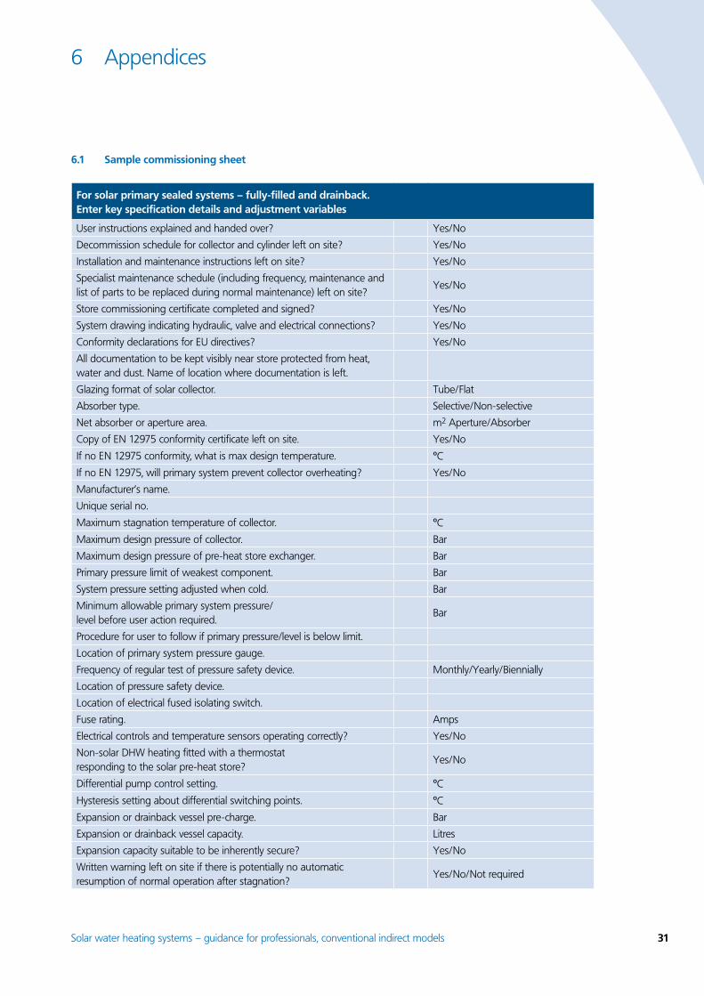
Solar water heating systems – guidance for professionals, conventional indirect models 31
6 Appendices
6.1 Sample commissioning sheet
For solar primary sealed systems – fully-filled and drainback. Enter key specification details and adjustment variables
User instructions explained and handed over? Yes/No
Decommission schedule for collector and cylinder left on site? Yes/No
Installation and maintenance instructions left on site? Yes/No
Specialist maintenance schedule (including frequency, maintenance and list of parts to be replaced during normal maintenance) left on site?
Yes/No
Store commissioning certificate completed and signed? Yes/No
System drawing indicating hydraulic, valve and electrical connections? Yes/No
Conformity declarations for EU directives? Yes/No
All documentation to be kept visibly near store protected from heat, water and dust. Name of location where documentation is left.
Glazing format of solar collector. Tube/Flat
Absorber type. Selective/Non-selective
Net absorber or aperture area. m2 Aperture/Absorber
Copy of EN 12975 conformity certificate left on site. Yes/No
If no EN 12975 conformity, what is max design temperature. ºCIf no EN 12975, will primary system prevent collector overheating? Yes/No
Manufacturer’s name.
Unique serial no.
Maximum stagnation temperature of collector. ºCMaximum design pressure of collector. Bar
Maximum design pressure of pre-heat store exchanger. Bar
Primary pressure limit of weakest component. Bar
System pressure setting adjusted when cold. Bar
Minimum allowable primary system pressure/level before user action required.
Bar
Procedure for user to follow if primary pressure/level is below limit.
Location of primary system pressure gauge.
Frequency of regular test of pressure safety device. Monthly/Yearly/Biennially
Location of pressure safety device.
Location of electrical fused isolating switch.
Fuse rating. Amps
Electrical controls and temperature sensors operating correctly? Yes/No
Non-solar DHW heating fitted with a thermostat responding to the solar pre-heat store?
Yes/No
Differential pump control setting. ºCHysteresis setting about differential switching points. ºCExpansion or drainback vessel pre-charge. Bar
Expansion or drainback vessel capacity. Litres
Expansion capacity suitable to be inherently secure? Yes/No
Written warning left on site if there is potentially no automatic resumption of normal operation after stagnation?
Yes/No/Not required

3� Solar water heating systems – guidance for professionals, conventional indirect models
For solar primary sealed systems – fully-filled and drainback. Enter key specification details and adjustment variables
Lowest ambient temperature of primary system without freeze damage. ºCThe heat transfer fluid provides freeze protection to. ºCType of transfer fluid. Water/Glycol
Maximum Ambient temp for pump. ºCMinimum ambient temperature for pump. ºCCirculation rate setting. Litres per minute
Noise at full circulation acceptable. Yes/No
Direction of circulation through collector and heat exchanger matched to sensor positions?
Yes/No
If drainback, pipes fall greater than 1:33 or filled with antifreeze? Yes/No
Solar pre-heat store type.Combined with DHW/Separate from DHW
Solar primary heat exchanger type. Copper/Steel/Plain/Ribbed
Solar primary heat exchanger area. m2
Volume of dedicated solar pre-heat. Litres
Location of DHW isolation valve.
Method of anti-scalding in DHW distribution.Pump control/thermostatic mixer valve
Location of digital temperature gauge fitted to monitor risk of DHW overheating.
Limescale risk to heat exchanger. Low/Medium/High
Limescale control in heat exchanger.Cleaning hatch/Thermostat on primary circulation
Expected annual delivered solar energy to taps. kWh
Expected annual solar fraction of DHW. per cent
Method of performance calculation. SAP2005/Other
Daily DHW load assumption. Litres per day at ºC
Date of site visits for bacterial, water quality and access risk assessments.
Commissioned by
On behalf of
Date system commissioned and handed over
Signature of commissioning engineer
Signature of user to confirm receipt and understanding (optional)

Solar water heating systems – guidance for professionals, conventional indirect models 33
6.� Annual solar radiation (kWh/m�)
Tilt of collector
Orientation of collector
SouthSouth-east/south-west East/west
North-east/North-west North
Horizontal 933
30° 1,042 997 886 762 709
45° 1,023 968 829 666 621
60° 960 900 753 580 485
Vertical 724 684 565 427 360
Figures taken from SAP2005 – Location Sheffield
6.3 Sample installation checklistFor solar sealed primary systems – drainback and fully-filled.
Ref Item Description Initials
1 Electrical wiring
Elec 1 All voltages – isolator
A double pole isolation for the fitted solar equipment i.e. controller/pump/valves, typically with a switched fused spur either located adjacent to the pump or DTC. If switching DC, it should be marked and rated for DC and should be labelled with the ON and OFF positions.
Elec 2 All voltages – supplementary
Supplementary (equipotential) earth bonding to be replaced where already present. Usually required for simultaneously accessible exposed and extraneous conductive parts. This typically includes pipes and pump housings, etc.
Elec 3 All voltages – pump
Solar pump or other similar solar primary item to be connected via heat resisting flex/cord (not fixed cable), marked at least to tolerate 85ºC and cable sheath clamp to be correctly used.
Elec 4 All voltages – support
Fixed wiring clipped correctly with mechanical protection (trunking, etc.) if at risk of physical impact. Minimum clip spacing 250mm horizontal, 400mm vertical. No PVC cable to be in contact with copper pipes. External cables greater than 30cm are to be supported. All cables to be protected from sharp edges, etc. by purpose guides or grommets.
Elec 5 All voltages – fuse Over-current protection should be present of the correct capacity for cables and connected appliances.
Elec 6 All voltages – sheath and wiring
Conductor sheath to be continuous into joint enclosures, conductors to be securely fastened to terminals, conductor insulation to be within 2mm of terminals.
Elec 7 All voltages – cable All cable conductors external of joint enclosures to be insulated and sheathed. External cables to be UV stable.
Elec 8 All voltages – class 2
Class 2 double insulation marked on all appliances normally intended for user operation.
Elec 9 Extra low voltage (ELV) – distinguish
All internal cables, conduits, connectors to be of a design or marking, totally dissimilar in appearance to any used for other voltage classes. In particular, plugs and sockets must not be interchangeable with those of other voltage bands.
Elec 10 ELV – segregation The separation between cables of different voltage classes should be at least 50mm, or placed in a separate conduit/trunking, or both insulated for highest voltage present.
Elec 11 ELV – common Where circuit for both voltage bands to share a common box, i.e. DTC, the connections of circuits of differing voltage bands must either: be segregated by a partition, which must be earthed if metallic, or there must be a 50mm clearance.

34 Solar water heating systems – guidance for professionals, conventional indirect models
Ref Item Description Initials
Elec 12 All voltages – enclosures
All electrical enclosures, including existing outlets from which spurs have been taken, to be refitted so as to ensure touch-proof connections and durability in service.
Elec 13 ELV – cable joints All cable joints to be touch-proof and in joint boxes suitable for the installed environment, e.g. IP20 indoor, IP56 outdoor.
Elec 14 All voltages – location
All controllers, pumps, etc. to be installed in suitable environments, not in bathrooms and not accessible to people using a bath or shower. Equipment mounts to be secure and durable for the life of the installation. Location to be accessible for service and user operation if intended (e.g. temperature displays to be visible where available).
Elec 15 PV generation – label
Any internal DC junction box from a PV generator should be labelled as ‘PV array junction box’, and also labelled with ‘Danger, contains live parts during daylight’. All labels should be durable, clear, easily visible and affixed to the enclosure.
Elec 16 PV generation – isolation
An electrical isolation switch is required to isolate the PV generator internally, either located adjacent to the pump or pump control. The switch must be double pole, switch must be marked with ‘rated for DC operation’ and should be labelled as ‘PV main isolator’, with the ON and OFF positions clearly marked. Switch enclosures should also be labelled with ‘Danger contains live parts during daylight’. All labels should be clear, easily visible, constructed and affixed to last and remain legible for the life of the enclosure.
Elec 17 PV generation – external
External wiring connecting to PV modules should be UV stable, water resistant and a flex/cord (not fixed cable). Entry to external junction boxes to be from the lowest edge, firmly fixed to the box. Box to be ventilated from below to prevent/reduce condensation risk. Cables should also be well supported, routed within prescribed zones or within mechanical protection. Cables should be protected from sharp edges.
Elec 18 PV generation – lightning
Lightning protection for PV module frames assessed according to BS 6651.
� Roof
Roof 1 The glazing seals are weather-tight and sound
Requires roof inspection. Where suspect, tested by 1 Bar water spray perpendicular and horizontal, then visual for drips/condensation mist inside glass.
Roof 2 Collector sensor clamped, insulated from ambient
If temperature sensor is present, it should be a good mechanical fix, insulated and not loose.
Roof 3 External pipes insulated
Where insulated, protected from UV, weather and vermin.
Roof 4 Shading No significant daily shading for more than two hours between spring and autumn.
Roof 5 Air vent isolated Any auto air vent near collector requires closed valve isolation during normal operation. OrWritten warning to user that there is potentially no auto-resume of operation after stagnation.
Roof 6 Roof fixings Requires roof inspection and within loft (to see sarking felt, etc). Where suspect, further tested by 1 Bar water spray perpendicular and horizontal then visual for drips/condensation. Fixings to be firmly attached to the roof structure and visual inspection that the roof covering is weatherproof.

Solar water heating systems – guidance for professionals, conventional indirect models 35
Ref Item Description Initials
3 Operation
Oper 1 Indicator of circulation
Safe means to verify the designed circulation to the end-user, i.e. two thermometers (Flow/return temperatures), flow-rate indicator or other fault indicator.
Oper 2 The recommended flow-rate is achieved through the primary circuit pipework
Requires an indicative flow indicator to be fitted i.e. in-line meter or electronic monitor. Flow rate checked against manufacturer’s recommendation. Engage override switch to test if solar gain is not present or observe normal circulatory function.
Oper 3 The levels in the cistern(s) or sealed system(s) are at the correct operating pressure
Pressure gauge dial (when fitted) to show at least greater than static head. Cistern (when fitted) to show at least 10 per cent of full capacity. Both checked when pump on and off. Drainback systems have various level monitors. Fluid levels checked against manufacturer’s recommendations.
Oper 4 Reverse flow protection
A device to prevent heat loss from unintentional reverse circulation.
Oper 5 Initial 100 Celsius prevention
Thermostatic control of secondary storage (i.e. shut-off primary circulation with automatic restart or self-setting temperature relief vale to EN 1490)
Oper 6 Secondary 100 Celsius prevention
Additional to Operation 5: unless a dedicated cold water cistern feeds the DHW store (i.e. is also open vented), then a manual reset device to cut off thermal energy (i.e. where collector wholly above store, then switch off pump or otherwise use motorised valve)
Oper 7 Tertiary 100 Celsius prevention
Additional to Operations 5 & 6: heat dissipation to control secondary storage to below 100ºC (i.e. open secondary vent, pressure/temperature relief valve).
Oper 8 The safety devices are operating correctly
Open vent and/or safety valve terminate in safe positions with low risk of accidental steam escape.
Oper 9 Gaseous bubbles expelled from the transmission liquid
Assessed by noise and through excessive noise with maximum circulation. Requires override switch to test or observe normal function if solar gain is not present.
Oper 10 Key system functions Provide indication of system function to user, i.e. circulation/pump indicator light, or visible float, or digital temperature indicators sensing collector and store temperature.
Oper 11 No condensation Check if damp spots are apparent, particularly around the pipework and fixings in the roof space.
Oper 12 Store sensor Store temperature readout which can withstand 100ºC with accuracy of ± 1ºC.
Oper 13 Downstream appliance thermostat
DHW generator downstream of pre-heat storage has thermostat which interlocks to pre-heat store.
Oper 14 Unsafe pre-heating of appliance
No direct pre-heating of combi or similar instantaneous water heaters unless factory designed.
Oper 15 Sizing for expansion Cistern, where fitted, large enough to avoid overflow during solar operation. Expansion vessel to be large enough to avoid safety valve operation during solar operation. Expansion volume calculated from the fluid that can vaporise under stagnation within the collector array, including interconnects, plus 10 per cent.
4 General
Gen 1 Contamination If fitted, temporary connection to sealed system should have double check valve (fitted to cold water side), control valves both sides and flexible hose disconnected. For cisterns, 20mm air break (or twice pipe diameter) to spill level at float valve.
Gen 2 Drain point Accessibly fitted on all low points, including pre-heat store.
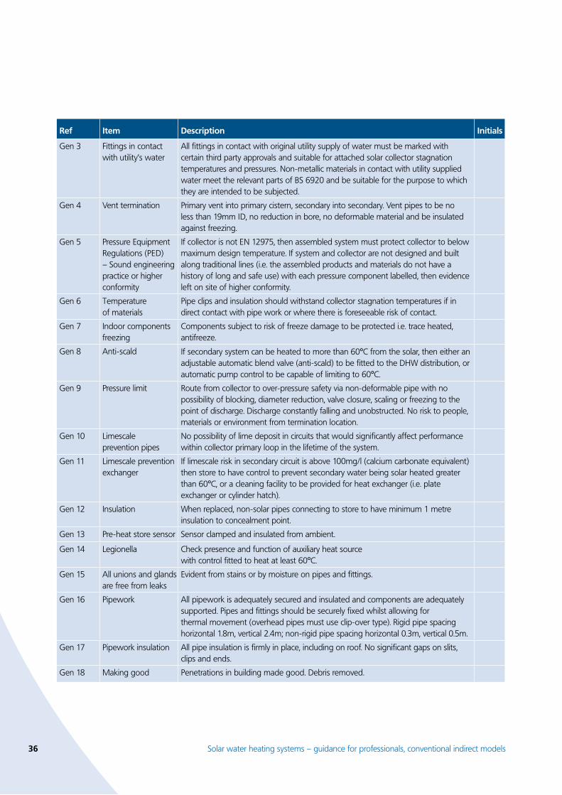
36 Solar water heating systems – guidance for professionals, conventional indirect models
Ref Item Description Initials
Gen 3 Fittings in contact with utility’s water
All fittings in contact with original utility supply of water must be marked with certain third party approvals and suitable for attached solar collector stagnation temperatures and pressures. Non-metallic materials in contact with utility supplied water meet the relevant parts of BS 6920 and be suitable for the purpose to which they are intended to be subjected.
Gen 4 Vent termination Primary vent into primary cistern, secondary into secondary. Vent pipes to be no less than 19mm ID, no reduction in bore, no deformable material and be insulated against freezing.
Gen 5 Pressure Equipment Regulations (PED) – Sound engineering practice or higher conformity
If collector is not EN 12975, then assembled system must protect collector to below maximum design temperature. If system and collector are not designed and built along traditional lines (i.e. the assembled products and materials do not have a history of long and safe use) with each pressure component labelled, then evidence left on site of higher conformity.
Gen 6 Temperature of materials
Pipe clips and insulation should withstand collector stagnation temperatures if in direct contact with pipe work or where there is foreseeable risk of contact.
Gen 7 Indoor components freezing
Components subject to risk of freeze damage to be protected i.e. trace heated, antifreeze.
Gen 8 Anti-scald If secondary system can be heated to more than 60ºC from the solar, then either an adjustable automatic blend valve (anti-scald) to be fitted to the DHW distribution, or automatic pump control to be capable of limiting to 60ºC.
Gen 9 Pressure limit Route from collector to over-pressure safety via non-deformable pipe with no possibility of blocking, diameter reduction, valve closure, scaling or freezing to the point of discharge. Discharge constantly falling and unobstructed. No risk to people, materials or environment from termination location.
Gen 10 Limescale prevention pipes
No possibility of lime deposit in circuits that would significantly affect performance within collector primary loop in the lifetime of the system.
Gen 11 Limescale prevention exchanger
If limescale risk in secondary circuit is above 100mg/l (calcium carbonate equivalent) then store to have control to prevent secondary water being solar heated greater than 60ºC, or a cleaning facility to be provided for heat exchanger (i.e. plate exchanger or cylinder hatch).
Gen 12 Insulation When replaced, non-solar pipes connecting to store to have minimum 1 metre insulation to concealment point.
Gen 13 Pre-heat store sensor Sensor clamped and insulated from ambient.
Gen 14 Legionella Check presence and function of auxiliary heat source with control fitted to heat at least 60ºC.
Gen 15 All unions and glands are free from leaks
Evident from stains or by moisture on pipes and fittings.
Gen 16 Pipework All pipework is adequately secured and insulated and components are adequately supported. Pipes and fittings should be securely fixed whilst allowing for thermal movement (overhead pipes must use clip-over type). Rigid pipe spacing horizontal 1.8m, vertical 2.4m; non-rigid pipe spacing horizontal 0.3m, vertical 0.5m.
Gen 17 Pipework insulation All pipe insulation is firmly in place, including on roof. No significant gaps on slits, clips and ends.
Gen 18 Making good Penetrations in building made good. Debris removed.

Solar water heating systems – guidance for professionals, conventional indirect models 37
6.4 Further reading
Solar standards
BS 7431 Method for assessing solar water heaters. Elastomeric materials for absorbers, connecting pipes and fittings.
BS 6785:1986 Code of practice for solar heating systems for swimming pools.
prEN 12977-3 Performance characterisation of stores for solar heating systems.
prEN 12977-2 Thermal solar systems and components. Custom built systems. Test methods.
prEN 12977-1 Thermal solar systems and components. Custom built systems. General requirements.
BS EN ISO 9488 Solar energy. Vocabulary.
BS EN 12976-2 Thermal solar systems and components. Factory made systems. Test methods.
BS EN 12976-1 Thermal solar systems and components. Factory made systems. General requirements.
BS EN 12975-2 Thermal solar systems and components. Solar collectors. Test methods.
BS EN 12975-1 Thermal solar systems and components. Solar collectors. General requirements.
Other relevant standardsBS 8000 Workmanship on building sites.
BS 7206 Specification for unvented hot water storage units and packages.
BS 7671 Requirements for electrical installations.
BS 1566 Copper indirect cylinders for domestic purposes.
BS 4814 Specifications for expansion vessels using an internal diagraph for sealed hot water heating systems.
BS 7074 Application, selection and installation of expansion vessels and ancillary equipment for sealed water systems.
BS 5422 Methods of specifying thermal insulation materials on pipes, ductwork and equipment in the temperature range of -40ºC to 700ºC.
BS 5449 BS EN 12831 BS EN 12828
Specification of forced circulation hot water central heating systems for domestic premises.
BS 6701 Telecommunications equipment and telecommunications cabling.
BS 5970 Code of practice for thermal insulation of pipes and equipment.
BS 6700 Specification and design, installation, testing and maintenance of services supplying water for domestic uses within buildings and their curtilages.
BS 6651 Lightning Protection – Code of practice for protection of structures against lightning.
BS 5534 Code of practice for roofing and tiling – Design.
BS 6399 BS 6399 BS 6920
Suitability of non-metallic products for use in contact with water intended for human consumption with regard to their effect on the quality of the water.

38 Solar water heating systems – guidance for professionals, conventional indirect models
6.5 RegulationsA simplified interpretation of some common regulations is shown below as it is found these are frequently disregarded. They are provided in good faith and should not be taken as the full meaning of the law. Any actions intended to be based on the law should refer to copies of published legislation typically available from The Stationery Office or be based on advice from a qualified practitioner of law. This text is of a general nature only and is not intended to address the specific circumstances of any particular individual or entity. It is not necessarily comprehensive, complete, accurate or up to date. Note that a ‘manufacturer’ of a SDHW system can on occasions be considered to be the commissioning engineers, particularly where custom components are being assembled.
UK Regulations particularly relevant for water heating equipment:Water Supply (Water Fittings) Regulations 1999 www.wras.org.ukApplies to all fittings in contact with the utilities’ supply of water. Responsibility of compliance lies with the householder and installer, although certain approved contractors can issue certificates of compliance which provide immunity from prosecution to the householder. All solar water heating work is normally notifiable to the water utility and permission must be awaited for ten days, except when installed in extensions or if alterations of water systems in existing houses. Water (over 15 litres) must not be stored in domestic premises above 100ºC, while avoidance of water contamination and undue consumption is mandatory.
There are requirements for protection from freezing, use of certified fittings, methods of pipe fixing, safety devices on water stores plus extra requirements for non-metallic fittings. Note that different requirements apply in Scotland and Northern Ireland.
The Pressure Equipment Regulations (PED) 1999 www.eurodyn.comApplies where the equipment could hold pressures in excess of 0.5 bar above atmospheric under any foreseeable circumstances. Applies to the manufacturer (where placed on the market as a functional assembly) or else the commissioning engineer. Requires equipment to be safe and either to a sound engineering practice or CE-marked to a higher safety requirement. Where an attached system can overheat according to BS EN 12976, the collector is categorised as a steam generator.
The Building Regulations (L1 A&B) 2006 and Domestic Heating Compliance Guide www.odpm.gov.ukApplies to the conservation of heat and power in all new build, extensions and existing dwellings. Particularly affects replacement of hot water storage vessels and accompanying controls. All solar water heating work normally involving additional hot water storage is therefore notifiable to a building control officer unless a competent person can self-certify and issue a commissioning certificate. Requires minimum levels for insulation, time and temperature controls for hot water storage. Also, water storage vessels to have a minimum performance. A commissioning certificate is required to be left. Note that different requirements apply in Scotland and Northern Ireland.
The Building Regulations (G3) 2000 www.odpm.gov.ukApplies to hygiene in buildings, particularly unvented hot water storage. Requires only competent operatives should install such certified equipment along with associated safety equipment.
The Building Regulations (P) 2005 www.odpm.gov.ukApplies to any electrical work that involves adding new circuits to dwellings and any work in special locations such as kitchens, bathrooms, swimming pools and PV power. A competent person must do the work and notify to a building control officer unless the person can self-certify. There are certain exceptions; it is permitted to add or replace outlets to existing circuits in non-special locations. All work should comply with, and further details may be found, in BS 7671.
Control of Substances Hazardous to Health Regulations (COSHH) 1994 www.hse.gov.ukRequire employers to assess the risks from hazardous substances and take appropriate precautions. This requires precautions to reduce legionella poisoning.
UK Regulations particularly relevant for construction:Further details available from: www.hse.gov.uk
Health & Safety At Work Act (HSW) 1974
Work at Height Regulations 2005.
Reporting of Injuries, Diseases and Dangerous Occurrences Regulations (RIDDOR) 1995.
•
•
•
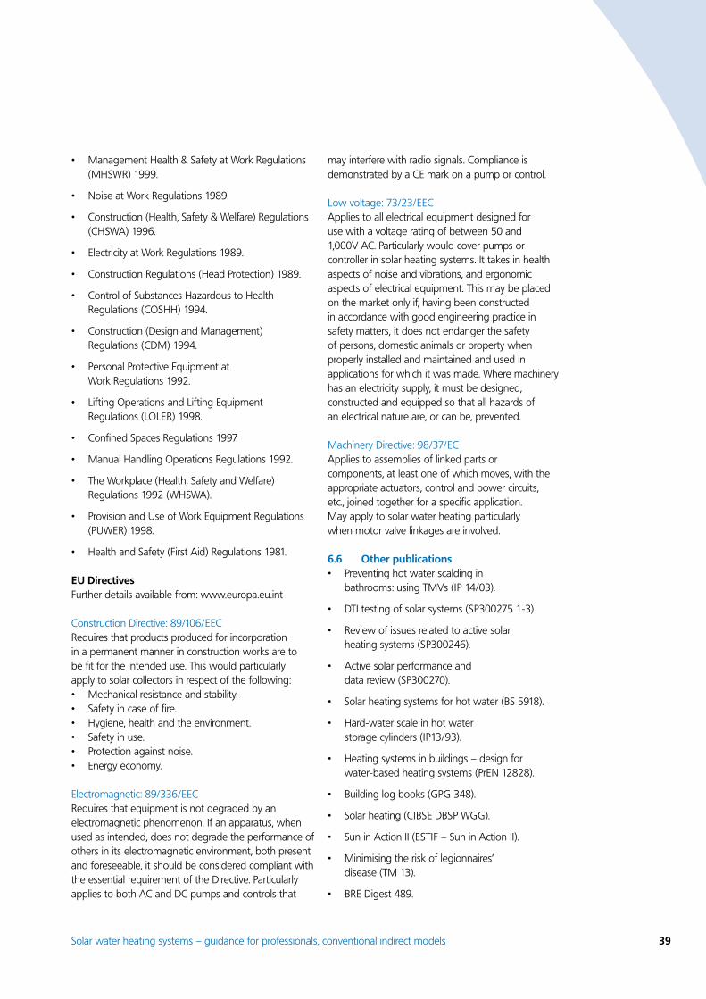
Solar water heating systems – guidance for professionals, conventional indirect models 3�
Management Health & Safety at Work Regulations (MHSWR) 1999.
Noise at Work Regulations 1989.
Construction (Health, Safety & Welfare) Regulations (CHSWA) 1996.
Electricity at Work Regulations 1989.
Construction Regulations (Head Protection) 1989.
Control of Substances Hazardous to Health Regulations (COSHH) 1994.
Construction (Design and Management) Regulations (CDM) 1994.
Personal Protective Equipment at Work Regulations 1992.
Lifting Operations and Lifting Equipment Regulations (LOLER) 1998.
Confined Spaces Regulations 1997.
Manual Handling Operations Regulations 1992.
The Workplace (Health, Safety and Welfare) Regulations 1992 (WHSWA).
Provision and Use of Work Equipment Regulations (PUWER) 1998.
Health and Safety (First Aid) Regulations 1981.
EU DirectivesFurther details available from: www.europa.eu.int
Construction Directive: 89/106/EECRequires that products produced for incorporation in a permanent manner in construction works are to be fit for the intended use. This would particularly apply to solar collectors in respect of the following:
Mechanical resistance and stability.Safety in case of fire.Hygiene, health and the environment.Safety in use.Protection against noise.Energy economy.
Electromagnetic: 89/336/EECRequires that equipment is not degraded by an electromagnetic phenomenon. If an apparatus, when used as intended, does not degrade the performance of others in its electromagnetic environment, both present and foreseeable, it should be considered compliant with the essential requirement of the Directive. Particularly applies to both AC and DC pumps and controls that
•
•
•
•
•
•
•
•
•
•
•
•
•
•
••••••
may interfere with radio signals. Compliance is demonstrated by a CE mark on a pump or control.
Low voltage: 73/23/EECApplies to all electrical equipment designed for use with a voltage rating of between 50 and 1,000V AC. Particularly would cover pumps or controller in solar heating systems. It takes in health aspects of noise and vibrations, and ergonomic aspects of electrical equipment. This may be placed on the market only if, having been constructed in accordance with good engineering practice in safety matters, it does not endanger the safety of persons, domestic animals or property when properly installed and maintained and used in applications for which it was made. Where machinery has an electricity supply, it must be designed, constructed and equipped so that all hazards of an electrical nature are, or can be, prevented.
Machinery Directive: 98/37/ECApplies to assemblies of linked parts or components, at least one of which moves, with the appropriate actuators, control and power circuits, etc., joined together for a specific application. May apply to solar water heating particularly when motor valve linkages are involved.
6.6 Other publicationsPreventing hot water scalding in bathrooms: using TMVs (IP 14/03).
DTI testing of solar systems (SP300275 1-3).
Review of issues related to active solar heating systems (SP300246).
Active solar performance and data review (SP300270).
Solar heating systems for hot water (BS 5918).
Hard-water scale in hot water storage cylinders (IP13/93).
Heating systems in buildings – design for water-based heating systems (PrEN 12828).
Building log books (GPG 348).
Solar heating (CIBSE DBSP WGG).
Sun in Action II (ESTIF – Sun in Action II).
Minimising the risk of legionnaires’ disease (TM 13).
BRE Digest 489.
•
•
•
•
•
•
•
•
•
•
•
•
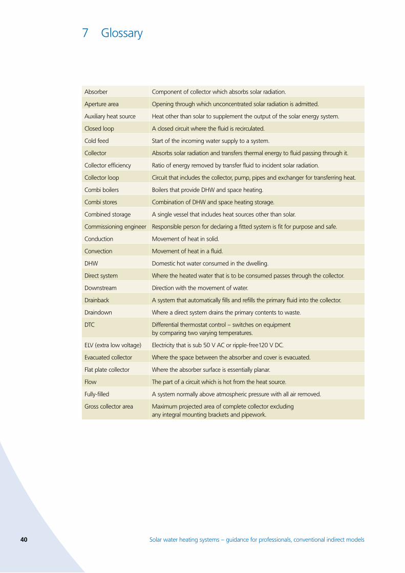
40 Solar water heating systems – guidance for professionals, conventional indirect models
7 Glossary
Absorber Component of collector which absorbs solar radiation.
Aperture area Opening through which unconcentrated solar radiation is admitted.
Auxiliary heat source Heat other than solar to supplement the output of the solar energy system.
Closed loop A closed circuit where the fluid is recirculated.
Cold feed Start of the incoming water supply to a system.
Collector Absorbs solar radiation and transfers thermal energy to fluid passing through it.
Collector efficiency Ratio of energy removed by transfer fluid to incident solar radiation.
Collector loop Circuit that includes the collector, pump, pipes and exchanger for transferring heat.
Combi boilers Boilers that provide DHW and space heating.
Combi stores Combination of DHW and space heating storage.
Combined storage A single vessel that includes heat sources other than solar.
Commissioning engineer Responsible person for declaring a fitted system is fit for purpose and safe.
Conduction Movement of heat in solid.
Convection Movement of heat in a fluid.
DHW Domestic hot water consumed in the dwelling.
Direct system Where the heated water that is to be consumed passes through the collector.
Downstream Direction with the movement of water.
Drainback A system that automatically fills and refills the primary fluid into the collector.
Draindown Where a direct system drains the primary contents to waste.
DTC Differential thermostat control – switches on equipment by comparing two varying temperatures.
ELV (extra low voltage) Electricity that is sub 50 V AC or ripple-free120 V DC.
Evacuated collector Where the space between the absorber and cover is evacuated.
Flat plate collector Where the absorber surface is essentially planar.
Flow The part of a circuit which is hot from the heat source.
Fully-filled A system normally above atmospheric pressure with all air removed.
Gross collector area Maximum projected area of complete collector excluding any integral mounting brackets and pipework.
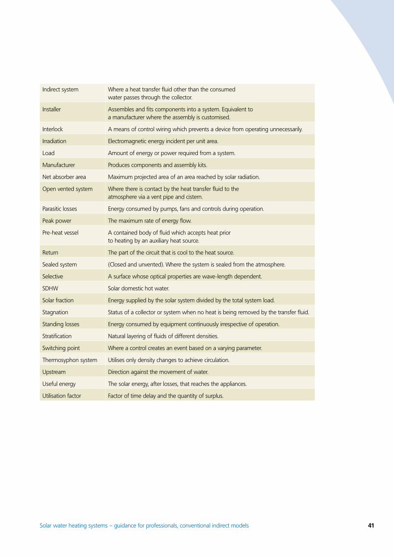
Solar water heating systems – guidance for professionals, conventional indirect models 41
Indirect system Where a heat transfer fluid other than the consumed water passes through the collector.
Installer Assembles and fits components into a system. Equivalent to a manufacturer where the assembly is customised.
Interlock A means of control wiring which prevents a device from operating unnecessarily.
Irradiation Electromagnetic energy incident per unit area.
Load Amount of energy or power required from a system.
Manufacturer Produces components and assembly kits.
Net absorber area Maximum projected area of an area reached by solar radiation.
Open vented system Where there is contact by the heat transfer fluid to the atmosphere via a vent pipe and cistern.
Parasitic losses Energy consumed by pumps, fans and controls during operation.
Peak power The maximum rate of energy flow.
Pre-heat vessel A contained body of fluid which accepts heat prior to heating by an auxiliary heat source.
Return The part of the circuit that is cool to the heat source.
Sealed system (Closed and unvented). Where the system is sealed from the atmosphere.
Selective A surface whose optical properties are wave-length dependent.
SDHW Solar domestic hot water.
Solar fraction Energy supplied by the solar system divided by the total system load.
Stagnation Status of a collector or system when no heat is being removed by the transfer fluid.
Standing losses Energy consumed by equipment continuously irrespective of operation.
Stratification Natural layering of fluids of different densities.
Switching point Where a control creates an event based on a varying parameter.
Thermosyphon system Utilises only density changes to achieve circulation.
Upstream Direction against the movement of water.
Useful energy The solar energy, after losses, that reaches the appliances.
Utilisation factor Factor of time delay and the quantity of surplus.

4� Solar water heating systems – guidance for professionals, conventional indirect models
Notes

This publication (including any drawings forming part of it) is intended for general guidance only and not as a substitute for the application of professional expertise. Anyone using this publication (including any drawings forming part of it) must make their own assessment of the suitability of its content (whether for their own purposes or those of any client or customer),
and the Energy Saving Trust cannot accept responsibility for any loss, damage or other liability resulting from such use. So far as the Energy Saving Trust is aware, the information presented in this publication was correct and current at time of last revision. To ensure you have the most up-to-date version, please visit our website: www.est.org.uk/housingbuildings/publications. The
contents of this publication may be superseded by statutory requirements or technical advances which arise after the date of publication. It is your responsibility to check latest developments.All technical information was produced by BRE on behalf of the Energy Saving Trust.
Printed on Revive Silk which contains 75% de-inked post consumer waste and a maximum of 25% mill broke.
CE131 © Energy Saving Trust March 2006. E&OE
Further information
The Energy Saving Trust sets energy efficiency standards that go beyond building regulations for use in the design, construction and refurbishment of homes. These standards provide an integrated package of measures covering fabric, ventilation, heating, lighting and hot water systems for all aspects of new build and renovation. Free resources including best practice guides, training seminars, technical advice and online tools, are available to help meet these standards.
The following publications may also be of interest:
Central Heating System Specifications (CHeSS) – Year 2005 (CE51/GIL59)
Domestic heating by gas: boiler systems (CE30)
Domestic heating by oil: boiler systems (CE29)
Domestic heating by solid fuel: boiler systems (CE47)
Solar hot water systems in new housing – a monitoring report (GIR88)
To obtain these publications or for more information, call 0845 120 7799, email [email protected] or visit www.est.org.uk/housingbuildings
•
•
•
•
•
Energy Saving Trust, 21 Dartmouth Street, London SW1H 9BP Tel 0845 120 7799 Fax 0845 120 7789 [email protected] www.est.org.uk/housingbuildings
CE131
Related Documents