Fluid Mechanics 2016 Prof. P. C. Swain Page 1 CE 15008 Fluid Mechanics LECTURE NOTES Module-III Department Of Civil Engineering VSSUT, Burla Prepared By Dr. Prakash Chandra Swain Professor in Civil Engineering Veer Surendra Sai University of Technology, Burla Branch - Civil Engineering in B Tech Semester – 4 th Semester

Welcome message from author
This document is posted to help you gain knowledge. Please leave a comment to let me know what you think about it! Share it to your friends and learn new things together.
Transcript

Fluid Mechanics 2016
Prof. P. C. Swain Page 1
CE 15008
Fluid
Mechanics
LECTURE NOTES
Module-III
Branch - Civil Engineering
B TECH
Semester – 4th
Semester
Department Of Civil Engineering
VSSUT, Burla
Prepared By
Dr. Prakash Chandra Swain
Professor in Civil Engineering
Veer Surendra Sai University of Technology, Burla
Branch - Civil Engineering in
B Tech
Semester – 4th
Semester
Fluid Mechanics 2016
Prof. P. C. Swain Page 2
Disclaimer
This document does not claim any originality and cannot be
used as a substitute for prescribed textbooks. The
information presented here is merely a collection by Prof. P.
C. Swain with the inputs of Post Graduate students for their
respective teaching assignments as an additional tool for the
teaching-learning process. Various sources as mentioned at
the reference of the document as well as freely available
materials from internet were consulted for preparing this
document. Further, this document is not intended to be used
for commercial purpose and the authors are not accountable
for any issues, legal or otherwise, arising out of use of this
document. The authors make no representations or
warranties with respect to the accuracy or completeness of
the contents of this document and specifically disclaim any
implied warranties of merchantability or fitness for a
particular purpose.

Fluid Mechanics 2016
Prof. P. C. Swain Page 3
COURSE CONTENT
CE 15008:
FLUID MECHANICS (3-1-0)
CR-04
Module – III (12 Hours)
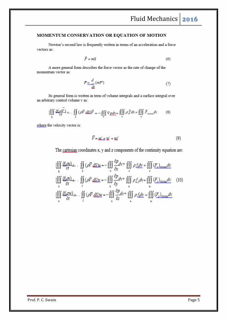
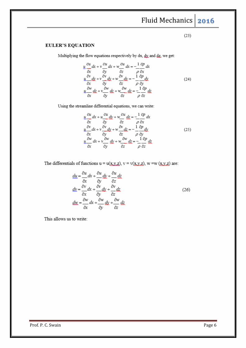
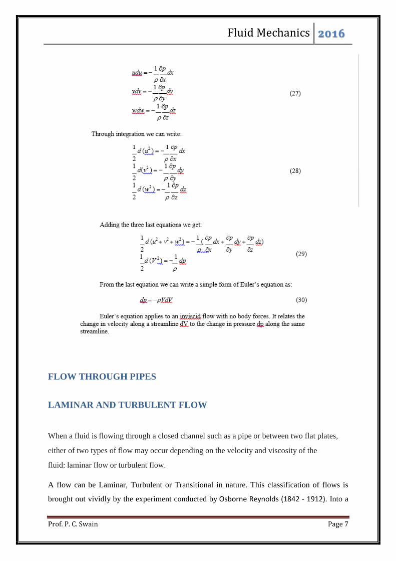
Fluid dynamics: Basic equations: Equation of continuity; One-dimensional Euler’s equation
of motion and its integration to obtain Bernoulli’s equation and momentum equation.
Flow through pipes: Laminar and turbulent flow in pipes; Hydraulic mean radius; Concept of
losses; Darcy-Weisbach equation; Moody’s (Stanton) diagram; Flow in sudden expansion
and contraction; Minor losses in fittings; Branched pipes in parallel and series, Transmission
of power; Water hammer in pipes (Sudden closure condition).

Fluid Mechanics 2016
Prof. P. C. Swain Page 4
Lecture Notes
Module 3
FLUID DYNAMICS
Fluid Mechanics 2016
Prof. P. C. Swain Page 5
Fluid Mechanics 2016
Prof. P. C. Swain Page 6
Fluid Mechanics 2016
Prof. P. C. Swain Page 7
FLOW THROUGH PIPES
LAMINAR AND TURBULENT FLOW
When a fluid is flowing through a closed channel such as a pipe or between two flat plates,
either of two types of flow may occur depending on the velocity and viscosity of the
fluid: laminar flow or turbulent flow.
A flow can be Laminar, Turbulent or Transitional in nature. This classification of flows is
brought out vividly by the experiment conducted by Osborne Reynolds (1842 - 1912). Into a
Fluid Mechanics 2016
Prof. P. C. Swain Page 8
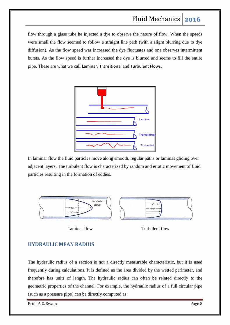
flow through a glass tube he injected a dye to observe the nature of flow. When the speeds
were small the flow seemed to follow a straight line path (with a slight blurring due to dye
diffusion). As the flow speed was increased the dye fluctuates and one observes intermittent
bursts. As the flow speed is further increased the dye is blurred and seems to fill the entire
pipe. These are what we call Laminar, Transitional and Turbulent Flows.
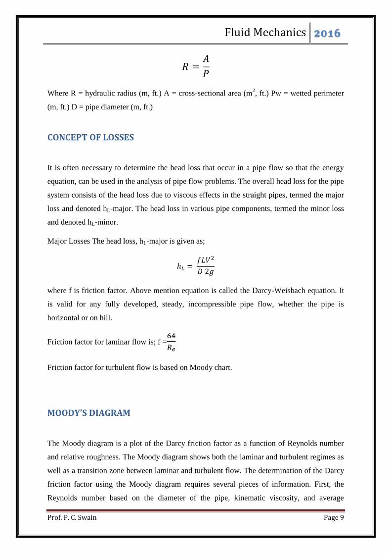
In laminar flow the fluid particles move along smooth, regular paths or laminas gliding over
adjacent layers. The turbulent flow is characterized by random and erratic movement of fluid
particles resulting in the formation of eddies.
Laminar flow Turbulent flow
HYDRAULIC MEAN RADIUS
The hydraulic radius of a section is not a directly measurable characteristic, but it is used
frequently during calculations. It is defined as the area divided by the wetted perimeter, and
therefore has units of length. The hydraulic radius can often be related directly to the
geometric properties of the channel. For example, the hydraulic radius of a full circular pipe
(such as a pressure pipe) can be directly computed as:
Fluid Mechanics 2016
Prof. P. C. Swain Page 9
Where R = hydraulic radius (m, ft.) A = cross-sectional area (m2, ft.) Pw = wetted perimeter
(m, ft.) D = pipe diameter (m, ft.)
CONCEPT OF LOSSES
It is often necessary to determine the head loss that occur in a pipe flow so that the energy
equation, can be used in the analysis of pipe flow problems. The overall head loss for the pipe
system consists of the head loss due to viscous effects in the straight pipes, termed the major
loss and denoted hL-major. The head loss in various pipe components, termed the minor loss
and denoted hL-minor.
Major Losses The head loss, hL-major is given as;
where f is friction factor. Above mention equation is called the Darcy-Weisbach equation. It
is valid for any fully developed, steady, incompressible pipe flow, whether the pipe is
horizontal or on hill.
Friction factor for laminar flow is; f =
Friction factor for turbulent flow is based on Moody chart.
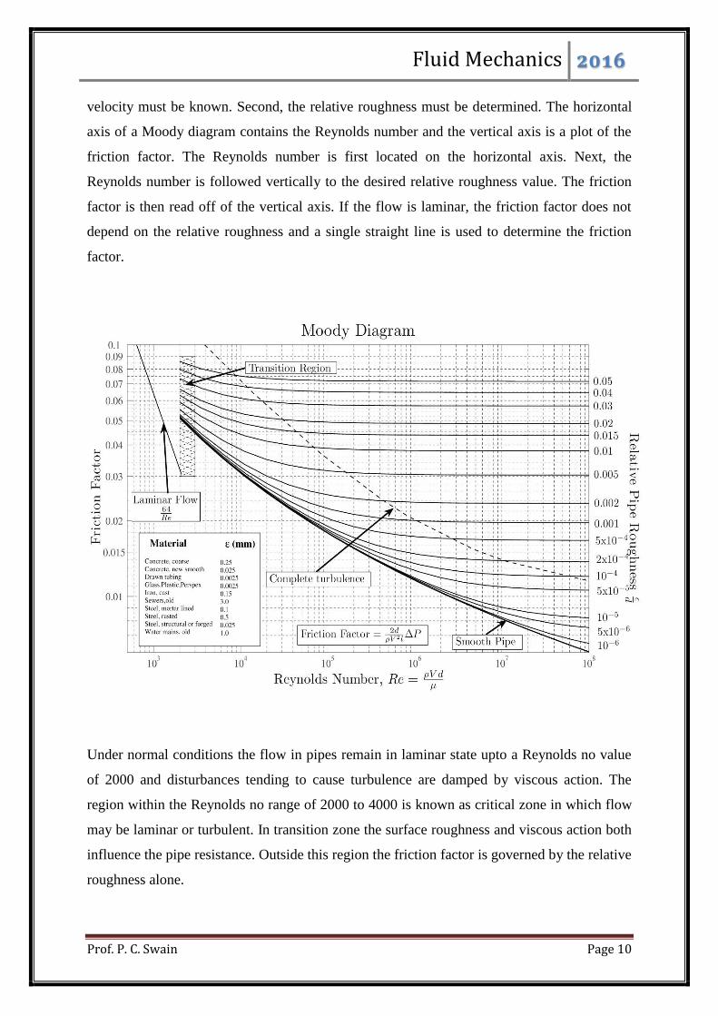
MOODY’S DIAGRAM
The Moody diagram is a plot of the Darcy friction factor as a function of Reynolds number
and relative roughness. The Moody diagram shows both the laminar and turbulent regimes as
well as a transition zone between laminar and turbulent flow. The determination of the Darcy
friction factor using the Moody diagram requires several pieces of information. First, the
Reynolds number based on the diameter of the pipe, kinematic viscosity, and average
Fluid Mechanics 2016
Prof. P. C. Swain Page 10
velocity must be known. Second, the relative roughness must be determined. The horizontal
axis of a Moody diagram contains the Reynolds number and the vertical axis is a plot of the
friction factor. The Reynolds number is first located on the horizontal axis. Next, the
Reynolds number is followed vertically to the desired relative roughness value. The friction
factor is then read off of the vertical axis. If the flow is laminar, the friction factor does not
depend on the relative roughness and a single straight line is used to determine the friction
factor.
Under normal conditions the flow in pipes remain in laminar state upto a Reynolds no value
of 2000 and disturbances tending to cause turbulence are damped by viscous action. The
region within the Reynolds no range of 2000 to 4000 is known as critical zone in which flow
may be laminar or turbulent. In transition zone the surface roughness and viscous action both
influence the pipe resistance. Outside this region the friction factor is governed by the relative
roughness alone.

Fluid Mechanics 2016
Prof. P. C. Swain Page 11
FLOW IN SUDDEN EXPANSION AND CONTRACTION
If the cross-section of a pipe with fluid flowing through it, is abruptly enlarged at
certain place, fluid emerging from the smaller pipe is unable to follow the abrupt
deviation of the boundary. The streamline takes a typical diverging pattern. This
creates pockets of turbulent eddies in the corners resulting in the dissipation of
mechanical energy into intermolecular energy. The fluid flows against an adverse
pressure gradient. The upstream pressure p1 at section a-b is lower than the
downstream pressure p2 at section e-f since the upstream velocity V1 is higher than the
downstream velocity V2 as a consequence of continuity. The fluid particles near the
wall due to their low kinetic energy cannot overcome the adverse pressure hill in the
direction of flow and hence follow up the reverse path under the favorable pressure
gradient (from p2 to p1). This creates a zone of re-circulating flow with turbulent
eddies near the wall of the larger tube at the abrupt change of cross-section, resulting
in a loss of total mechanical energy. For high values of Reynolds number, usually
found in practice, the velocity in the smaller pipe may be assumed sensibly uniform
over the cross section. Due to the vigorous mixing caused by the turbulence, the
velocity becomes again uniform at a far downstream section e-f from the enlargement
(approximately 8 times the larger diameter).
A control volume abcdefgh is considered for which the momentum theorem can be written as
Where A1, A2 are the cross-sectional areas of the smaller and larger parts of the pipe
respectively, Q is the volumetric flow rate and p’ is the mean pressure of the eddying fluid
over the annular face, gd. It is known from experimental evidence, the p’ = p1.
Hence the Eq. becomes
From the equation of continuity
Applying Bernoulli's equation between sections ab and ef in consideration of the flow to be
incompressible and the axis of the pipe to be horizontal, we can write
Fluid Mechanics 2016
Prof. P. C. Swain Page 12
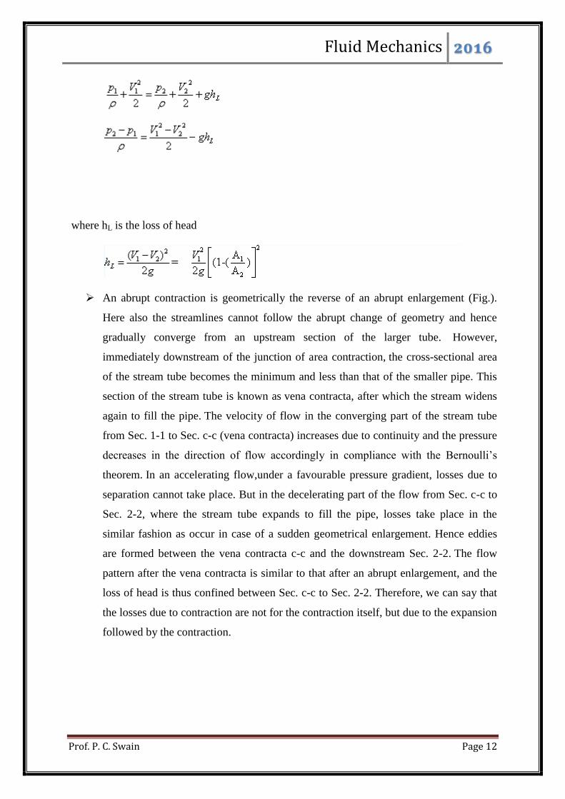
where hL is the loss of head
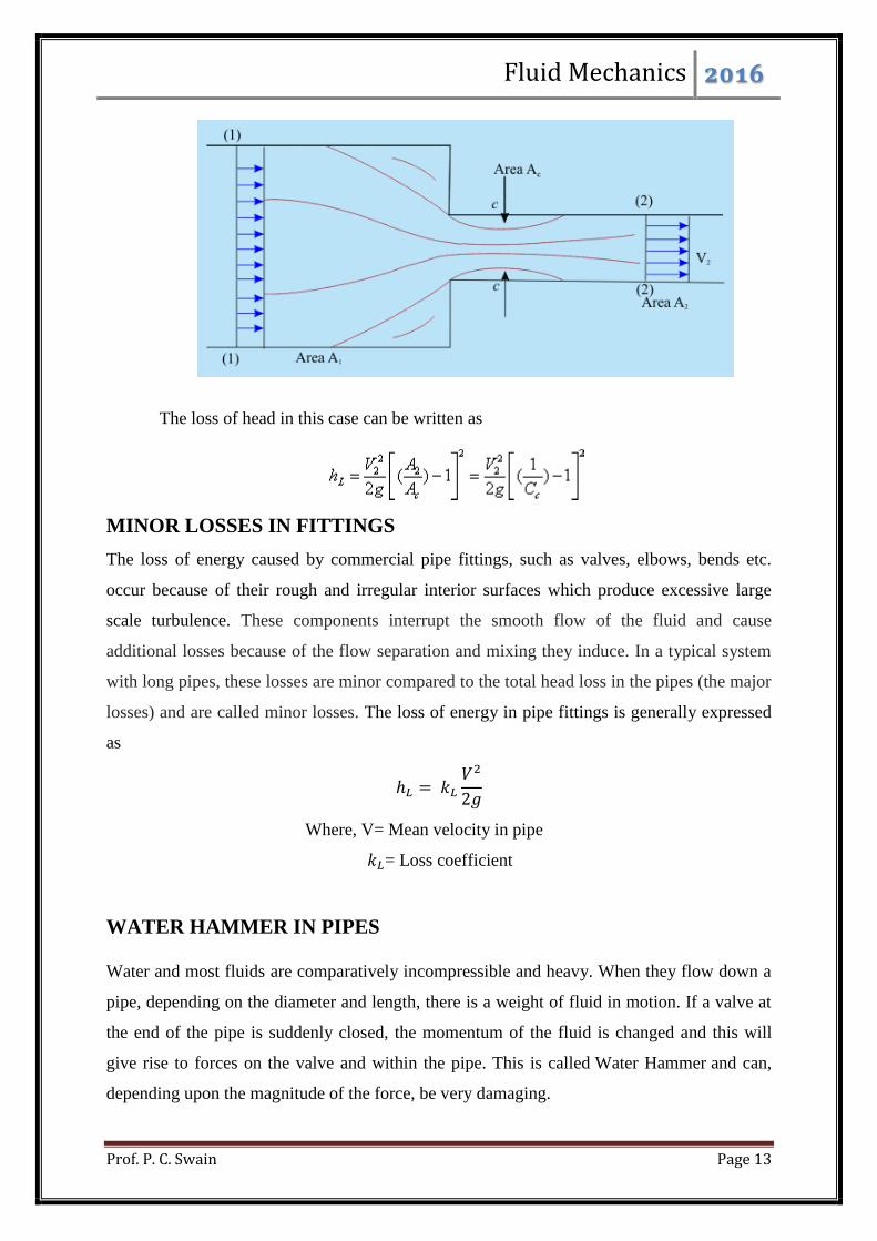
An abrupt contraction is geometrically the reverse of an abrupt enlargement (Fig.).
Here also the streamlines cannot follow the abrupt change of geometry and hence
gradually converge from an upstream section of the larger tube. However,
immediately downstream of the junction of area contraction, the cross-sectional area
of the stream tube becomes the minimum and less than that of the smaller pipe. This
section of the stream tube is known as vena contracta, after which the stream widens
again to fill the pipe. The velocity of flow in the converging part of the stream tube
from Sec. 1-1 to Sec. c-c (vena contracta) increases due to continuity and the pressure
decreases in the direction of flow accordingly in compliance with the Bernoulli’s
theorem. In an accelerating flow,under a favourable pressure gradient, losses due to
separation cannot take place. But in the decelerating part of the flow from Sec. c-c to
Sec. 2-2, where the stream tube expands to fill the pipe, losses take place in the
similar fashion as occur in case of a sudden geometrical enlargement. Hence eddies
are formed between the vena contracta c-c and the downstream Sec. 2-2. The flow
pattern after the vena contracta is similar to that after an abrupt enlargement, and the
loss of head is thus confined between Sec. c-c to Sec. 2-2. Therefore, we can say that
the losses due to contraction are not for the contraction itself, but due to the expansion
followed by the contraction.
Fluid Mechanics 2016
Prof. P. C. Swain Page 13
The loss of head in this case can be written as
MINOR LOSSES IN FITTINGS
The loss of energy caused by commercial pipe fittings, such as valves, elbows, bends etc.
occur because of their rough and irregular interior surfaces which produce excessive large
scale turbulence. These components interrupt the smooth flow of the fluid and cause
additional losses because of the flow separation and mixing they induce. In a typical system
with long pipes, these losses are minor compared to the total head loss in the pipes (the major
losses) and are called minor losses. The loss of energy in pipe fittings is generally expressed
as
Where, V= Mean velocity in pipe
= Loss coefficient
WATER HAMMER IN PIPES
Water and most fluids are comparatively incompressible and heavy. When they flow down a
pipe, depending on the diameter and length, there is a weight of fluid in motion. If a valve at
the end of the pipe is suddenly closed, the momentum of the fluid is changed and this will
give rise to forces on the valve and within the pipe. This is called Water Hammer and can,
depending upon the magnitude of the force, be very damaging.
Fluid Mechanics 2016
Prof. P. C. Swain Page 14
Water hammer (or, more generally, fluid hammer) is a pressure surge or wave caused when
a fluid (usually a liquid but sometimes also a gas) in motion is forced to stop or change
direction suddenly (momentum change). A water hammer commonly occurs when a valve
closes suddenly at an end of a pipeline system, and a pressure wave propagates in the pipe. It
is also called hydraulic shock. This pressure wave can cause major problems, from noise and
vibration to pipe collapse.
When a pipe is suddenly closed at the outlet (downstream), the mass of water before the
closure is still moving, thereby building up high pressure and a resulting shock wave. In
domestic plumbing this is experienced as a loud banging, resembling a hammering noise.
Water hammer can cause pipelines to break if the pressure is high enough. Air traps or stand
pipes (open at the top) are sometimes added as dampers to water systems to absorb the
potentially damaging forces caused by the moving water.
On the other hand, when an upstream valve in a pipe closes, water downstream of the valve
attempts to continue flowing, creating a vacuum that may cause the pipe to collapse
or implode. This problem can be particularly acute if the pipe is on a downhill slope. To
prevent this, air and vacuum relief valves, or air vents, are installed just downstream of the
valve to allow air to enter the line for preventing this vacuum from occurring.
Fluid Mechanics 2016
Prof. P. C. Swain Page 15
References
Text Books:
1. Fluid mechanics by A.K. Jain, Khanna Publishers.
Reference Books:
1. Hydraulics and Fluid Mechanics including Hydraulic Machines by P.N.Modi and S.M.
Seth, Standard Book House.
2. Engineering Fluid Mechanics by K.L. Kumar, S. Chand & Co.
3. Fluid Mechanics by V.L. Streeter, MGH
Related Documents