European X-Ray Free-Electron Laser Facility GmbH Albert-Einstein-Ring 19 22761 Hamburg Germany XFEL.EU TR-2011-007 CONCEPTUAL DESIGN REPORT Scientific Instrument Single Particles, Clusters, and Biomolecules (SPB) January 2012 A.P. Mancuso for Scientific Instrument SPB (WP84) at the European XFEL

Welcome message from author
This document is posted to help you gain knowledge. Please leave a comment to let me know what you think about it! Share it to your friends and learn new things together.
Transcript

European X-Ray Free-Electron Laser Facility GmbH
Albert-Einstein-Ring 19
22761 Hamburg
Germany
XFEL.EU TR-2011-007
CONCEPTUAL DESIGN REPORT
Scientific Instrument Single Particles, Clusters, and Biomolecules (SPB)
January 2012
A.P. Mancuso
for Scientific Instrument SPB (WP84)
at the European XFEL

January 2012 XFEL.EU TR-2011-007 2 of 96 CDR: Scientific Instrument SPB
Contents
1 Overview and summary ................................................................................... 4
Objective ............................................................................................................. 4 Goals ................................................................................................................... 5 Approach ............................................................................................................. 5 Background and rationale ................................................................................... 6 Three key classes of experiments ...................................................................... 7
2 Advisory review team ..................................................................................... 12
Role ................................................................................................................... 12 Members ........................................................................................................... 12
3 Note on contributions .................................................................................... 15
4 Photon beam properties ................................................................................ 17
Radiation from the SASE1 undulator ................................................................ 17 Experiment modelling program ......................................................................... 20
5 Optical layout .................................................................................................. 27
Goals of the SPB optical layout ........................................................................ 27 Outline of the SPB instrument .......................................................................... 28 Choice of focusing technology .......................................................................... 30 Conclusions ...................................................................................................... 44 “Beyond baseline” optics options ...................................................................... 44 Other optical elements ...................................................................................... 46
6 Sample environment and delivery ................................................................ 48
General sample environment............................................................................ 48 Sample injection technology ............................................................................. 49 Fixed sample-mounting system ........................................................................ 52 Additional sample injection technology (option) ............................................... 53
7 Instrument diagnostics systems ................................................................... 55
Beam position monitors (BPMs) ....................................................................... 55 Screens ............................................................................................................. 56 Single-shot flux monitors .................................................................................. 56 Fluorescence spectrometer .............................................................................. 57 Wavefront measurement device (WMD) .......................................................... 57 Single-shot λ spectrometer ............................................................................... 58 “Intelligent” beamstop ....................................................................................... 59 Coherence monitor ........................................................................................... 59 Alignment laser ................................................................................................. 59 Timing monitor .................................................................................................. 60

XFEL.EU TR-2011-007 January 2012 CDR: Scientific Instrument SPB 3 of 96
8 Pump laser delivery ........................................................................................ 61
Laser ................................................................................................................. 61 Delivery of laser radiation to the interaction region .......................................... 62 Wavelength tunability of the pump laser ........................................................... 63
9 Detector system .............................................................................................. 65
2D detectors ...................................................................................................... 66 1D detectors ...................................................................................................... 72 Optional additional detector(s) .......................................................................... 72
10 Data acquisition, management, and analysis .............................................. 74
Outline ............................................................................................................... 74 Data acquisition ................................................................................................ 75 Data management ............................................................................................ 76 Scientific computing .......................................................................................... 78 Conclusions ...................................................................................................... 78
11 Conclusions and outlook ............................................................................... 79
A Limitations on maximum sample size .......................................................... 81
Sampling considerations ................................................................................... 81
B Sundry optical layouts ................................................................................... 85
Alternative optics for the 1 μm focal spot .......................................................... 85 Alternative optics for the sub-100 nm focal spot ............................................... 89 Alternative for the refocused focal spot ............................................................ 89 Conclusions ...................................................................................................... 89
C Estimate of data rate ...................................................................................... 90
D Abbreviations .................................................................................................. 91
E References ....................................................................................................... 92
January 2012 XFEL.EU TR-2011-007 4 of 96 CDR: Scientific Instrument SPB
1 Overview and summary
This chapter describes the objective, goals, background, rationale, and
classes of experiments for the Single Particles, Clusters, and Biomolecules
(SPB) instrument.
Objective
The Single Particles, Clusters, and Biomolecules (SPB) instrument aims to
image single particles by exploiting coherent diffraction imaging and
associated methods using hard X-ray free-electron laser (FEL) radiation. In
particular, the SPB instrument’s goals have been discussed with the coherent
imaging community, and are recorded in the document titled “International
workshop on science with and instrumentation for ultrafast coherent
diffraction imaging of Single Particles, clusters and Biomolecules (SPB) at the
European XFEL” [1].
Specifically, the SPB instrument will be designed to image single particles,
which explicitly includes:
Isolated, non-crystalline biomolecules
Nanocrystals of biomolecules
Atomic clusters
Other isolated, single particles, in particular those of a “reproducible”
nature
Furthermore, the SPB instrument aims to investigate the structure of these
systems, as a function of time, through the use of so-called “pump-probe”
measurements, where an optical laser excites a sample and the FEL probes
it some delay time later (for example, see [2]).

XFEL.EU TR-2011-007 January 2012 CDR: Scientific Instrument SPB 5 of 96
Goals
The goal of the SPB instrument is to be a world-leading instrument, making
possible the science listed in “Objective” on page 4. The goal of this
document is to outline the conceptual design of the SPB instrument, one of
the initial six instruments to be installed and operated at the future
European XFEL facility in Hamburg and Schenefeld, Germany [3]. This
includes descriptions of the major subsystems of the SPB instrument,
including the instrument’s optics, the sample injection environment, the
detector(s) required, and the necessary diagnostics in the end station. This
document is a conceptual design report, and, as such, does not include all
the details required to construct the instrument. A more detailed technical
design report (TDR) will be produced subsequent to this document.
Approach
One of the key properties of the conceptual design is the balance between a
clear, realistic design and the flexibility required to adapt to the changing
needs of single particle imaging, which is rapidly developing due to the recent
commencement of operation of hard X-ray FELs in the USA [4] and in
Japan [5]. Parts of this document propose more than one solution to the
instrument design. In particular, this occurs when it is technically not
challenging to maintain flexibility in the design (e.g. interchangeable, low-cost
optics) or where a given, available technology is able to solve only a subset of
the problems above and another technology better solves another subset of
problems (e.g. different focusing optics for single particle imaging compared
with nanocrystallography).

January 2012 XFEL.EU TR-2011-007 6 of 96 CDR: Scientific Instrument SPB
Background and rationale
This document is primarily informed by the user workshop entitled
“International workshop on science with and instrumentation for ultrafast
coherent diffraction imaging of Single Particles, Clusters and Biomolecules
(SPB) at the European XFEL” held in Uppsala, Sweden, in November 2008.
The workshop’s content and purpose can be summarized by the following
observation:
“The study of structural properties of single particles, clusters, and bio-
molecules (SPB) using coherent X-ray diffraction by particles in the gas
phase is one of the prioritized areas of science for the upcoming Europe-
an XFEL facility. These experiments will be relevant to several areas of
science, reaching from materials and nano-sciences to biology. The
workshop brought together scientists interested in experiments using the
SPB instrument at the European XFEL facility to review the science
planned with this instrument, to discuss the requirements to the X-ray
FEL beam delivery, and to initiate activities and collaborations on instru-
mentation and facilities needed at this photon end station.” [1]
The full program of the workshop (including copies of presenters’ slides) can
be found on the SPB Workshop 2008 webpage:
http://www.xfel.eu/events/workshops/2008/spb_workshop_2008/
This page also includes the subsequent report summarizing the workshop’s
findings [1].
Single particle imaging becomes feasible due to the unprecedented photon
flux and spatial coherence of FEL sources. The highest X-ray flux available
(hence FEL) is needed to be able to measure and interpret the still very weak
signal one expects from single particles. Furthermore, many shots or frames
of data are required for successful interpretation of that data [6] [7]. On this
front, the European XFEL has a unique advantage due to the unprecedented
pulse rate produced by the superconducting accelerator technology used.
With access to orders of magnitude more pulses compared to other facilities
around the world, the SPB instrument, it is hoped, will explore science that is

XFEL.EU TR-2011-007 January 2012 CDR: Scientific Instrument SPB 7 of 96
broader than that currently possible at existing FEL sources, for example by
investigating the dynamics of these samples in the pump-probe mode with
many different delay times or exploring the breadth of conformations present
in a single molecule.
A variety of methods for structure determination will be available at the SPB
instrument, including (but not limited to) single particle imaging and
nanocrystallography. This will allow the investigation of structural biology in
samples that are impossible to study without FEL radiation. Furthermore, the
SPB instrument will provide the opportunity to explore the fundamental
physics of intense X-ray photon-matter interactions through the use of single-
or few-element controlled samples, such as atomic clusters.
Three key classes of experiments
One can group the proposed experiments to be performed at the SPB
instrument into three key classes, based on (i) the sample to be investigated,
(ii) the requirements on the beam to investigate a given type of sample, and
(iii) the expected signal scattered from the sample after interaction with the
European XFEL beam.
Single particle imaging of biomolecules
One class of interest is single biomolecules and macromolecular complexes.
These samples are typically some tens of nanometers in their longest
dimension and are composed of predominantly carbon, nitrogen, and oxygen.
The X-ray scattering from such an object is, as expected, very weak; as such,
maximizing the single pulse photon flux delivered to the sample is critical for
this class of experiments. This requirement imposes the constraint that the X-
ray optics used to focus and deliver the FEL beam to the sample must be
highly transmissive, with the largest fraction of the beam being delivered to
the interaction region in a focal spot comparable to (≈ 2–3 x) the size of the
sample. Even given the ultrabright nature of the XFEL pulses, the signal
expected from such a sample at the detector may be as small as some few
tens of photons across an entire 2D detector [6] [7], placing stringent
requirements of single photon sensitivity on the 2D detector used.
January 2012 XFEL.EU TR-2011-007 8 of 96 CDR: Scientific Instrument SPB
Furthermore, as the knowledge of atomic positions is of considerable
importance for the broadest success of single molecule imaging, the
instrument geometry should accommodate the collection of scattering data
down to 2 Å resolution or better [8] [9].
Also critical is the transverse intensity and wavefront distribution of the beam
incident on the sample. Variations in the incident beam’s structure on the
scale of the features to be imaged will themselves contribute to the measured
signal and final image, unless they are themselves characterized and
accounted for in the imaging process [10] [11]. This places stringent
requirements on the X-ray optics to minimize intensity and wavefront
structure, due to apertures and optical aberrations, as well as on the X-ray
diagnostics to measure and characterize any such variations.
The summary requirements to this class of experiment are:
Maximum number of photons delivered to the sample, in a spot size
comparable with the sample size
Flat, uniform, or characterizable wavefront in the focal plane
Single photon sensitive detector (elaborated in Chapter 9, “Detector
system”, on page 65)
Means to deliver particles to the interaction region at a rate that matches
the X-ray pulse rate
Resolutions better than 2 Å
Nanocrystallography
Samples for nanocrystallography are, as the name suggest, crystalline. To
date, samples down to hundreds of nanometers in size have been
investigated [12]. As for the biomolecules case described in “Single particle
imaging of biomolecules” on page 7, it is desirable to maximize the scattered
signal by using high transmission optics and by matching the focal size to the
sample size. In the simplest nanocrystallographic analysis, a highly controlled
or characterized wavefield is not required, and the crystallographic phase
problem is solved using a generalization of traditional crystallographic
techniques [13]. Accordingly, as in conventional crystallography, there is a

XFEL.EU TR-2011-007 January 2012 CDR: Scientific Instrument SPB 9 of 96
need for many pixels in the detector to accurately determine the centre of
each Bragg peak measured.
Beyond that, a further analysis of nanocrystallographic data, which utilizes the
coherent diffraction information around a Bragg peak [14], has the same
requirements on the incident wavefield as the single particle case above,
namely a flat or well-characterized intensity and wavefront distribution.
However, unlike for the investigation of weakly scattering single biomolecules,
the analysis of the data around the Bragg peaks requires a large dynamic
range in the detector. The signal around a Bragg peak quickly decreases with
distance from the centre of the peak.
The summary requirements to this class of experiment are:
Maximum number of photons delivered to the sample, in a spot size
comparable with the crystal size
High number of pixels in the detector for accurate centroid determination
of Bragg peaks
For the most thorough analysis, a flat, uniform, or characterizable
wavefront in the focal plane
High dynamic range in the detector
Wavelength tunability around elemental absorption edges
Nanocrystal delivery or mounting system that replenishes samples at a
rate that matches the X-ray pulse rate
Resolutions better than 2 Å

January 2012 XFEL.EU TR-2011-007 10 of 96 CDR: Scientific Instrument SPB
Figure 1. A simulated diffraction pattern around a Bragg peak produced by an
icosahedral-shaped crystal. The signal shown here (on a log scale) spans more than
three orders of magnitude. Weaker signal from the simulation has been suppressed
by a modelled noise-floor.
Larger single particles
Larger biological samples, such as small cells, organelles, or viruses, or more
strongly scattering samples, such as materials science samples composed of
heavier elements, present a third category of experiments that is envisaged
for the SPB instrument. These samples will create a continuous diffraction
pattern that spans many orders of magnitude in its dynamic range. Here the
beam requirements are similar to the most stringent cases described above,
except the required focal spots are likely to be larger. The control or
characterization of the incident intensity and wavefront is also essential for a
thorough analysis in these cases.
The demands on detection are most pertinent in the requirement of a high
dynamic range, as the scattered signal falls off rapidly with angle in the
diffraction pattern. Ultimately, this effect limits the resolution of any
reconstruction. Subunits of cells, such as the Nuclear Pore Complex [15], can
be hundreds of nanometers in size. Useful resolutions are then on the single-
digit nanometer range, giving access to hundreds of resolution elements
across these type of sub-cellular assemblies. As the scattering signal
decreases proportionally to the fourth power of feature size, the desired
number of resolution elements places a direct requirement on the dynamic
range of the detector or detector system, ideally to span the number of
resolution elements to the fourth power.
XFEL.EU TR-2011-007 January 2012 CDR: Scientific Instrument SPB 11 of 96
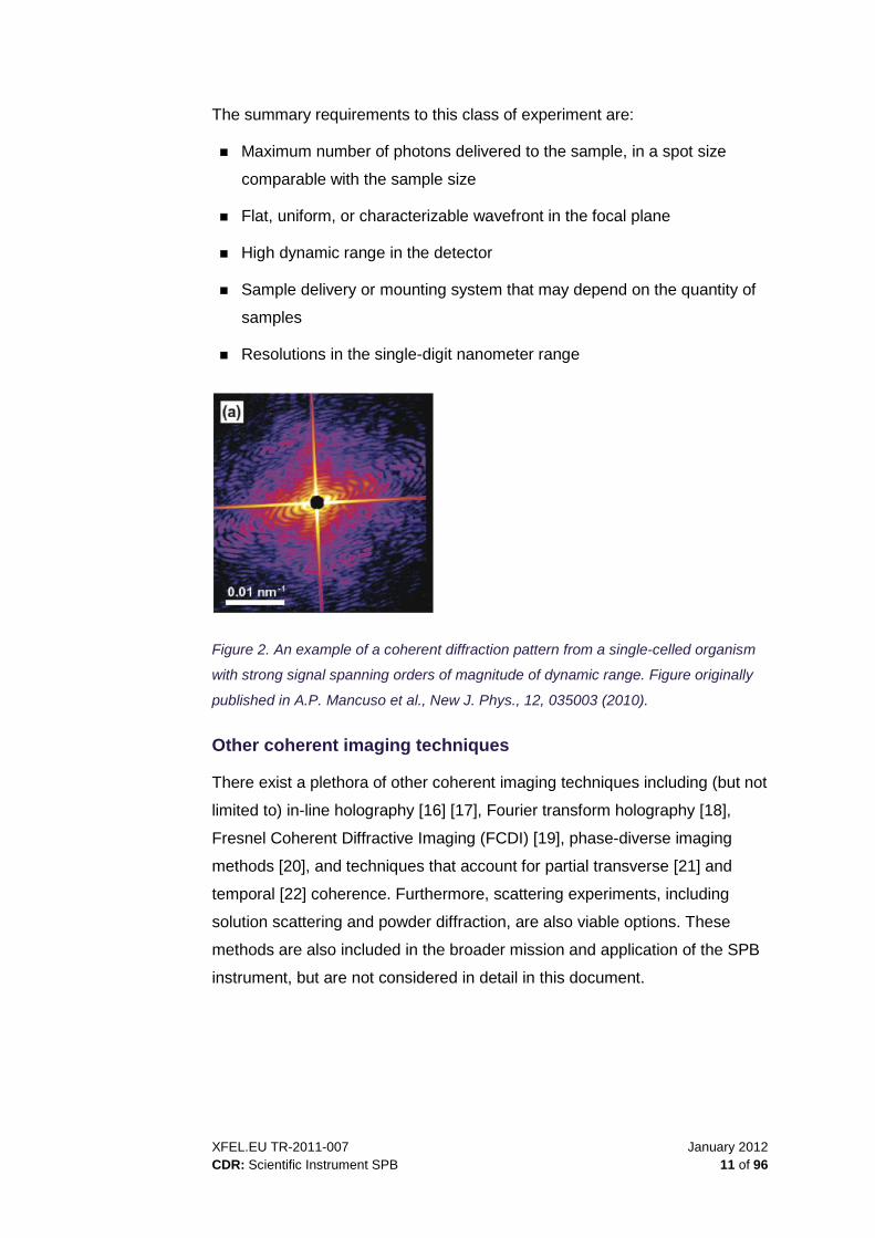
The summary requirements to this class of experiment are:
Maximum number of photons delivered to the sample, in a spot size
comparable with the sample size
Flat, uniform, or characterizable wavefront in the focal plane
High dynamic range in the detector
Sample delivery or mounting system that may depend on the quantity of
samples
Resolutions in the single-digit nanometer range
Figure 2. An example of a coherent diffraction pattern from a single-celled organism
with strong signal spanning orders of magnitude of dynamic range. Figure originally
published in A.P. Mancuso et al., New J. Phys., 12, 035003 (2010).
Other coherent imaging techniques
There exist a plethora of other coherent imaging techniques including (but not
limited to) in-line holography [16] [17], Fourier transform holography [18],
Fresnel Coherent Diffractive Imaging (FCDI) [19], phase-diverse imaging
methods [20], and techniques that account for partial transverse [21] and
temporal [22] coherence. Furthermore, scattering experiments, including
solution scattering and powder diffraction, are also viable options. These
methods are also included in the broader mission and application of the SPB
instrument, but are not considered in detail in this document.

January 2012 XFEL.EU TR-2011-007 12 of 96 CDR: Scientific Instrument SPB
2 Advisory review team
This chapter describes the role of the advisory review team (ART) and lists its
members.
Role
The ART is a panel of experts in diverse matters related to single particle
imaging. The ART provides advice on the design of the SPB instrument and
also provides a review function to give feedback on the SPB design and
implementation.
The ART is expected to review the instrument’s conceptual and technical
design as well as to provide advice and feedback continuously until the
instrument’s final delivery.
Members
Prof. Dr Franz Pfeiffer (Chair) Physics Department (E17) and Institute of Medical Engineering (IMETUM)
Technische Universität München
James-Franck-Straße
85748 Garching
Germany
Phone: +49 89 289 12552
Fax: +49 89 289 12548

XFEL.EU TR-2011-007 January 2012 CDR: Scientific Instrument SPB 13 of 96
Dr Sebastien Boutet CXI Instrument Scientist
LCLS, SLAC Accelerator Laboratory
2575 Sand Hill Rd
Menlo Park, CA 95205
USA
Phone: +1 650 926 8676
Fax: +1 650 926 3600
Dr Garth Williams
CXI Instrument Scientist
LCLS, SLAC Accelerator Laboratory
2575 Sand Hill Rd
Menlo Park, CA 95205
USA
Phone: +1 650 926 2682
Fax: +1 650 926 3600
Dr Anton Barty
Centre for Free-Electron Laser Science
Deutsches Elektronen-Synchrotron (DESY)
Notkestraße 85
D-22607 Hamburg
Germany
Phone: +49 40 8998 5783
Fax: +49 40 8998 1958

January 2012 XFEL.EU TR-2011-007 14 of 96 CDR: Scientific Instrument SPB
Dr Dan DePonte
Centre for Free-Electron Laser Science
Deutsches Elektronen-Synchrotron (DESY)
Notkestraße 85
D-22607 Hamburg
Germany
Phone: +49 40 8998 5784
Fax: +49 40 8998 1958
Prof. Dr Ilme Schlichting Director, Dept. of Biomolecular Mechanisms
Max Planck Institute for Medical Research
Jahnstraße 29
69120 Heidelberg
Germany
Phone: +49 6221 486-500
Fax: +49 6221 486-351
Prof. Dr Victor Lamzin
Deputy Head of Outstation and Senior Scientist
European Molecular Biology Laboratory (EMBL) Hamburg
Deutsches Elektronen-Synchrotron (DESY)
Notkestraße 85
22603 Hamburg
Germany
Phone: +49 40 8990 2121
Fax: +49 40 8990 2149

XFEL.EU TR-2011-007 January 2012 CDR: Scientific Instrument SPB 15 of 96
3 Note on contributions
Many people have contributed to this conceptual design report. A number of
experts have contributed significantly to different chapters through text,
diagrams, or otherwise.
These experts are:
Expert Area
Harald Sinn, European XFEL Optical Layout
Liubov Samoylova, European XFEL X-ray Focus Simulation
Max Lederer, European XFEL Pump Laser
Chris Youngman, European XFEL Data Acquisition, Management, and Analysis
Krzysztof Wrona, European XFEL Data Management
Burkhard Heisen, European XFEL Scientific Computing
Markus Kuster, European XFEL Detectors
Julian Becker, DESY Experiment Modelling Program: Detector Effects
Heinz Graafsma, DESY Experiment Modelling Program: Detector Effects
Dan DePonte, Centre for Free-Electron Laser Science, DESY
Sample Injection Technology
Zoltan Jurek, Centre for Free-Electron Laser Science, DESY
Photon–Matter Interaction Simulation
Beata Ziaja, Centre for Free-Electron Laser Science, DESY
Photon–Matter Interaction Simulation
The above experts are thanked for their exemplary contributions. Any errors
remaining in this document are entirely the responsibility of the author.
Valuable discussions were held with a variety of members of the single
particle imaging community and the FEL community. Sébastien Boutet and
Garth Williams of the Coherent X-Ray Imaging (CXI) instrument at LCLS,
SLAC National Accelerator Laboratory, USA, provided a wealth of advice and

January 2012 XFEL.EU TR-2011-007 16 of 96 CDR: Scientific Instrument SPB
information based on their experience at CXI to date. Anton Barty and Henry
Chapman have generously provided practical insights into methods of data
collection utilized in recent single particle imaging and nanocrystallography
experiments performed by the team of the Centre for Free-Electron Laser
Science at DESY in Hamburg, Germany. Mike Pivovaroff and Stefan Hau-
Riege of Lawrence Livermore National Laboratory provided valuable
correspondence on the feasibility of Silicon Carbide-on-metal mirror bilayer
coatings for FEL applications. Duane Loh of SLAC provided clear insight into
structure determination methods for the 3D imaging of very weakly scattering
specimens. Oleg Chubar, Alexey Buzmakov, and Liubov Samoylova are
responsible for the cross-platform, wave-optics software, SRWLib, used to
simulate the focal properties of the SPB instrument. Evgeny Schneidmiller
and Michael Yurkov provided simulations of the FEL photon beam properties
for a variety of operating parameters. Alke Meents of DESY, Hamburg,
generously provided valuable insights into X-ray optics and instrumentation,
and Janos Hajdu provided background on the nature of the biological
samples the SPB instrument aims to investigate.
Valuable feedback on this text was provided by Thomas Tschentscher of the
European XFEL and as well as Massimo Altarelli, Andreas Schwarz, and
Serguei Molodtsov, all members of the European XFEL Management Board.
Michael Meyer, Anders Madsen, and Christian Bressler, all leading scientists
at the European XFEL, are also thanked for their feedback on the conceptual
design and layout. Andrew Aquila and Klaus Giewekemeyer provided
valuable suggestions on this document’s contents and expression. Kurt
Ament assisted enormously with the presentation, layout, and editing.
The ART and the Scientific Advisory Committee of the European XFEL have
contributed review comments and insights to the next stage of design of the
SPB instrument. Their diligent work in providing advice and feedback is also
thoroughly appreciated.

XFEL.EU TR-2011-007 January 2012 CDR: Scientific Instrument SPB 17 of 96
4 Photon beam properties
This chapter describes the radiation from the SASE1 undulator and the
experiment modelling program that, amongst other goals, aims to model the
photon beam properties at the sample.
Radiation from the SASE1 undulator
The SPB instrument will be located in the centre beamline after the SASE1
undulator of the European XFEL, as shown in Figure 3.
Figure 3. Layout of the European XFEL accelerator, undulator, and X-ray beam
transport systems. Note that the SPB instrument is located after the SASE1
undulator. Figure sourced from [23].
Table 1, taken from [24], contains calculated values for properties of the
radiation produced by this undulator. We note that, in general, the beam is
highly spatially coherent, with the degree of coherence reducing for harder
energy X-rays or higher bunch charge in the accelerator (that is, higher
photon flux). The source size is expected to be between about 30 and 50 μm
FWHM across a range of different parameters.

January 2012 XFEL.EU TR-2011-007 18 of 96 CDR: Scientific Instrument SPB
Table 1. Photon beam parameters for SASE1 as a function of machine operating
parameters for some photon energies in the SPB instrument’s range of operation,
from 3 to 16 keV. Note well that these parameters are given for operation at
saturation. The pulse energy, for example, is likely to increase for operation in the
oversaturated regime.
Parameter Unit Value
Photon energy keV 7.75 12.4 15.5
Radiation wavelength nm 0.16 0.10 0.08
Electron energy GeV 14 14 14
Bunch charge nC 0.02 0.25 1 0.02 0.25 1 0.02 0.25 1
Peak power GW 46 37 24 35 24 12 29 15 9
Average power W 2 23 69 2 15 34 1 9 27
Source size (FWHM) µm 31 39 46 29 37 49 29 35 54
S. divergence (FWHM) µrad 2.8 2.3 1.9 1.9 1.5 1.3 1.5 1.3 1.0
Spectral bandwidth 1E-3 2.3 1.9 1.4 1.9 1.4 1.0 1.6 1.3 0.8
Coherence time fs 0.16 0.20 0.27 0.13 0.17 0.23 0.12 0.15 0.23
Coherence degree 0.96 0.96 0.91 0.95 0.91 0.71 0.96 0.84 0.57
Photons/pulse 1E11 0.6 7.0 20.7 0.3 2.8 6.4 0.2 1.4 4.0
Pulse energy µJ 76 864 2570 58 549 1260 49 347 991
Peak brilliance 1E33* 2.38 2.41 1.96 3.54 3.17 1.6 4.26 2.46 1.6
Average brilliance 1E23* 1.1 15.1 56.8 1.6 19.9 46.4 1.9 15.5 46.2
* In units of photons/(mm2 mrad2 0.1% bandwidth s)
In Table 2, again from [24], we see the desired operating range of the SPB
instrument, its proposed range of beam size as requested at the SPB
workshop [1] and its proposed bandwidth. The proposed bandwidth to be
used is the natural bandwidth of the FEL (ΔE/E ≈ 1 × 10⁻³). This document
outlines the addition of a monochromator in Chapter 5, “Optical layout”, on
page 27.

XFEL.EU TR-2011-007 January 2012 CDR: Scientific Instrument SPB 19 of 96
Table 2. Fundamental operating parameters of the SPB instrument, as discussed at
the SPB workshop [1] and modified from that tabulated in [24].
Scientific instrument
Photon energy [kev]
Bandwidth ∆ω/ω
Beam size [µm] Special optics
SPB 3–16 natural 0.1–10; < 1 000
Extreme focusing
The European XFEL is designed to be capable of producing pulses of less
than 10 fs in duration for sub-100 pC bunch charges. In order to utilise the
“diffract-and-destroy” principle, it is expected that pulse durations below 10 fs
are necessary [25] [26]. For other applications, such as nanocrystallography,
these duration constraints appear to be significantly reduced, with pulses of
hundreds of femtoseconds duration viable in some cases [27]. However, for
single particles and nanocrystals, the key parameter to maximize is pulse
intensity, achieved with the highest pulse power. A peak power of 46 GW
focused to a 0.1 micron diameter spot would give a maximum of
4.6 × 10²⁰ W/cm2.
Table 3. Pulse duration as a function of bunch charge [24]
Parameter Unit Value
Bunch charge pC 20 100 250 500 1 000
Pulse duration (FWHM) fs 2 9 23 43 107

January 2012 XFEL.EU TR-2011-007 20 of 96 CDR: Scientific Instrument SPB
Experiment modelling program
This section describes the goals, participants, and progress of the experiment
modelling program, as well as the related X-ray optics and propagation code
and photon–matter interaction simulation.
Goals
As modelling the FEL operating parameters is essential to inform appropriate
planning of the facility, it is also desirable to model simplified instances of
experiments that are expected to be performed in the end stations. This
informs the technical design of the instruments, helps understand potential
bottlenecks, and ultimately allows us to possess a tool capable of evaluating
expected signal levels for designing and understanding the feasibility of
proposed experiments.
A modelling program for SPB has been started that aims to achieve these
goals through:
Simulating the different stages of the experiment, starting with the
generation of the radiation
Modeling its transport to the interaction region
Modeling the photon-matter interaction between the FEL beam and a
model sample
Propagating the radiation to the 2D detector system and its measurement
in that detector system
Interpreting the measured data
This ambitious program is modular in design, with modules focusing on each
of the above stages of the overall system (see Figure 4). This allows the
project participants to work independently on each of the stages listed above,
which can then be combined into a complete start-to-end (S2E) simulation to
model an entire (albeit simplified) experiment. Of particular relevance here
will be its usefulness in verifying this conceptual design and informing the
subsequent technical design of the SPB instrument.

XFEL.EU TR-2011-007 January 2012 CDR: Scientific Instrument SPB 21 of 96
Figure 4. Organization of the start-to-end (S2E) simulation program
Participants
A variety of collaborators from different institutions in the Hamburg area are
taking part in each of the S2E’s modules and are listed in Table 4.
Table 4. List of participants (to November 2011) in the start-to-end (S2E) simulation
program
Name Organization Role
Liubov Samoylova European XFEL X-ray optics, propagation code
Beata Ziaja CFEL Photon–Matter Interaction Simulation
Zoltan Jurek CFEL Photon–Matter Interaction Simulation
Markus Kuster European XFEL Detector Effects
Julian Becker DESY Detector Effects
Heinz Graafsma DESY Detector Effects
Mikhail Yurkov DESY Source photon field simulations
Evgeny Schneidmiller DESY Source photon field simulations
Krzysztof Wrona European XFEL Scientific Computing, Image Reconstruction
Burkhard Heisen European XFEL Scientific Computing, Image Reconstruction
Adrian Mancuso European XFEL Coordinator, Image Reconstruction
Thomas Tschentscher European XFEL Director responsible for optics and SPB
Source Optics Sample Photon/Matter Interaction Propagation to Detector
Measurement at Detector Analysis and Reconstruction Sample Structure
Source Optics Photon/Matter Interaction Detector Analysis
Physically, the pulses propagate through the instrument in the following steps:
The project is organized into the following modules:

January 2012 XFEL.EU TR-2011-007 22 of 96 CDR: Scientific Instrument SPB
Progress
The key progress to date has been defining the modules and their
corresponding responsible partners. At present, each module has at least one
functioning simulation code that could contribute to the overall goals of the
project. The technical interfaces between each module are, at the time of
writing, being defined to allow the efficient communication of information from
each module to its corresponding downstream recipient. The progress in the
individual components is described below.
X-ray optics and propagation code
The X-ray optics and propagation code has been thoroughly utilized in the
“Optical Layout” section later in this document to simulate transverse and
longitudinal beam profiles after passing through the SPB optics, for different
beam parameters. This code [28], designed for XFEL applications, presently
assumes the beam is fully spatially coherent, which is a very good
approximation in practice for realistic parameters of an FEL beam [29] [30].
Photon–matter interaction simulation
The CFEL theory team has performed an initial simulation using a human
three-phosphoglycerate kinase molecule (atomic coordinates from the pdb
database, pdb id: 2YBE). This molecule consists of 3 240 atoms in a volume
of approximately 50 x 50 x 70 Å3. As the first step of the project, the team of
the Photon-Matter Interaction module calculated the structure factor F of a
static molecule, e.g. without any radiation damage within the structure. The
atomic form factors were calculated using the XATOM package [31]. The
scattering data were calculated on a grid in reciprocal space. The minimum
density of grid points is defined by the size of the molecule, but we chose a
grid with six times more points (in each linear direction) than that required by
Shannon sampling, to have a finer sampling appropriate for the imaging
module of the project. The size of the volume in reciprocal space was defined
by the desired resolution of 2 Å. According to these values, the total number
of grid points is around 100 million resulting in 16 GB of data in HDF5 format
[32]. A visualization of this data is shown in Figure 5.

XFEL.EU TR-2011-007 January 2012 CDR: Scientific Instrument SPB 23 of 96
Figure 5. Visualization of the 3D simulated diffraction data from a three-
phosphoglycerate kinase molecule.
Detector effects
The detector effects team has developed a simulation tool, called HPAD
Output Response Function Simulator (HORUS), which has been used to
estimate the detector effects on model data. HORUS is a detector simulation
tool for modelling the relevant physical and electronic processes impacting
the detective quantum efficiency of the Adaptive Gain Integrating Pixel
Detector (AGIPD) [33] [34], which is one of the European XFEL detectors
considered appropriate for the SPB instrument.
HORUS is a collection of routines aimed at the systematic study of the impact
of certain detector design choices. The program is written using a modular
structure, following step by step the various physical and electrical processes
involved in the photon detection and signal generation process, as shown in
Figure 6.

January 2012 XFEL.EU TR-2011-007 24 of 96 CDR: Scientific Instrument SPB
Figure 6. HORUS detector simulation processing chain. Image courtesy of Julian
Becker, DESY, Hamburg.
The implemented models to describe the physical processes were purposely
kept simple, but can be refined in future versions, if necessary. The
underlying default simulation parameters are constantly updated as more
data becomes available from the evaluation of the AGIPD test chips.
The detector simulation tool is part of the AGIPD project for the European
XFEL and thus reflects the implementation of this detector. HORUS can be
used both to study the overall detector performance as a function of various
technological choices, and to simulate the degradation of any input image in
order to study its impact on the scientific application.
Source photon field simulations
The source field simulation team has delivered time-dependent simulations of
the source photon fields for different bunch charge operation modes of the
accelerator. This data will be used as the initial input to the modelling
program, when the links between the modules are established. As interim
inputs, Gaussian beams of comparable size and divergence to these

XFEL.EU TR-2011-007 January 2012 CDR: Scientific Instrument SPB 25 of 96
simulations are used. Already, data for 0.1, 0.25, and 0.5 nC bunch charge
are available with photon energies of 8 and 12 keV.
Scientific computing and image reconstruction
The data format envisaged for storing, exchanging, and recording the history
of scientific data samples will be based on Hierarchical Data Format 5
(HDF5) [32]. HDF5 is capable of describing complex data objects and
associated metadata in a platform-independent format. Data representation is
self-describing in the sense that the format defines all the information
necessary to read and reconstruct original objects of an abstract data model.
The software libraries are available on a broad range of computational
platforms and programming languages, which makes the data analysis highly
portable. A collection of generic tools exists for managing, manipulating,
viewing, and analysing data. HDF5 has recently become the standard format
for handling data in many scientific disciplines, at other photon light sources,
and in particular at LCLS. The high-level interface definition and its
implementation optimizing access to large datasets, hiding the complexity of
various data management aspects, and maintaining portability will be
provided by the Data Acquisition, Data Management, and Scientific
Computing teams within the European XFEL software framework.
This software framework is envisaged to also assist in processing and
visualizing the image data. Predefined modules will be available that have to
be extended only by the specific data processing routines. Common
challenges like data input/output, handling configuration settings, error
treatment, logging, multi-threading, etc. will already be solved within the pre-
defined part of the modules. The modules may then be chained to form
higher-level data-analysis pipelines of arbitrary complexity. New modules will
automatically be available (plug-and-play mechanism) within the provided
graphical user interface (GUI) for individual configuration and running, and
also be available as building blocks of a user-defined analysis pipeline. The
Data Acquisition, Data Management, and Scientific Computing group plans to
also provide highly optimized standard image processing routines (rotations,
filters, FFT, etc.) making use of e.g. GPU technology as part of the European
XFEL software framework. These tools will be used in the final stage of the
modelling program, to reconstruct images form the modelled data, and to

January 2012 XFEL.EU TR-2011-007 26 of 96 CDR: Scientific Instrument SPB
evaluate the fidelity of these reconstructions as a function of the instrument’s
optical layout, sample type, detector parameters, etc.

XFEL.EU TR-2011-007 January 2012 CDR: Scientific Instrument SPB 27 of 96
5 Optical layout
This section describes the goals of the SPB optical layout, provides an
overview of the SPB instrument, and explains the choice of focusing
technology. It also describes options that go beyond baseline optics as well
as additional optical elements.
Goals of the SPB optical layout
The optical layout of the SPB instrument must respect the requirements
presented by the three key categories of experiments outlined earlier in this
document.
Specifically, across the operating photon energy range of the instrument, the
optical design should ensure that:
Maximum number of photons is delivered to the sample in a spot size
comparable to the sample size.
Minimally perturbed wavefront in the focal plane is delivered.
The SPB instrument will pursue two different-sized focal spots to match
samples of different sizes, as outlined in the SPB Workshop summary
document [1]. One will be a focal spot slightly larger than 1 μm, which can
accommodate samples as a large as the hutch geometry and pixel size of the
detector (see Appendix A, “Limitations on maximum sample size”, on
page 81) will allow. The other will be a sub-100 nm spot size to accommodate
the smallest samples on the order of tens of nanometers.
These goals need to be achieved within the constraints of the beam size and
divergence of the FEL beam, both determined by the source itself and the
optical elements encountered during propagation. A summary of the expected
beam sizes and divergences for the SPB instrument, as a function of photon
energy, are given in Table 5.

January 2012 XFEL.EU TR-2011-007 28 of 96 CDR: Scientific Instrument SPB
Table 5. Beam size and divergence at the experiment hall as a function of photon
energy [23]. The upper and lower values of divergence refer to cases of differing
bunch charge in the accelerator.
Photon energy [keV]
FWHMupper [mm]
FWHMlower [mm]
Divergence [μrad]*
3 5.57 3.10 6.18
5 3.80 2.01 4.22
8 2.67 1.34 2.96
10 2.26 1.11 2.51
12 1.97 0.95 2.19
15 1.66 0.79 1.85
* Divergences are calculated for the lowest bunch charge
As can be seen, the beam in the most extreme case is very large in the
experiment hall, especially for the lower photon energies, and is still large
even in the expected lower bound. This is mainly due to the large propagation
distance between the undulator and the experiment hall. It is this beam size,
coupled with the science requirements stated above, that provide the
boundary conditions for the optical design described in the following section.
Outline of the SPB instrument
The SPB instrument aims to use Kirkpatrick-Baez (KB) mirrors to deliver a
spot slightly larger than 1 μm as well as a sub-100 nm spot to a common
focal plane or “interaction region”. At this point, the sample is injected (or in
some cases mounted), the details of which are described in Chapter 6,
“Sample environment and delivery”, on page 48. Further downstream of the
interaction region, a 2D detector is required to be located at distances from as
close as possible to the interaction region through to at least 10 m
downstream of the interaction region. This large variation is required to allow
both the measurement of scattering signals from the smallest expected
samples to angles commensurate with near atomic resolution, and to allow
for appropriate sampling of diffraction patterns from samples as large as
XFEL.EU TR-2011-007 January 2012 CDR: Scientific Instrument SPB 29 of 96
about a micron for a coherent imaging-type inversion across the operating
energy range of the instrument (see Appendix A, “Limitations on maximum
sample size” on page 81). Following the detector is a so-called “intelligent”
beamstop to measure shot-to-shot beam properties, and is described in more
detail in Chapter 7, “Instrument diagnostics systems” on page 55. Upstream
of the mirrors are further diagnostics and beam conditioning elements, such
as slits prior to each optical element, to protect the optics in case they are
overfilled with the beam, and attenuators to allow non-destructive beamline
alignment to be performed.
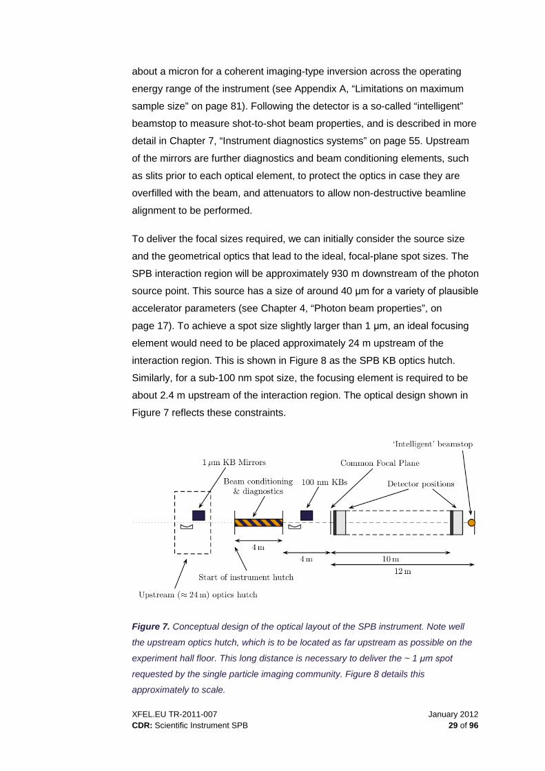
To deliver the focal sizes required, we can initially consider the source size
and the geometrical optics that lead to the ideal, focal-plane spot sizes. The
SPB interaction region will be approximately 930 m downstream of the photon
source point. This source has a size of around 40 μm for a variety of plausible
accelerator parameters (see Chapter 4, “Photon beam properties”, on
page 17). To achieve a spot size slightly larger than 1 μm, an ideal focusing
element would need to be placed approximately 24 m upstream of the
interaction region. This is shown in Figure 8 as the SPB KB optics hutch.
Similarly, for a sub-100 nm spot size, the focusing element is required to be
about 2.4 m upstream of the interaction region. The optical design shown in
Figure 7 reflects these constraints.
Figure 7. Conceptual design of the optical layout of the SPB instrument. Note well
the upstream optics hutch, which is to be located as far upstream as possible on the
experiment hall floor. This long distance is necessary to deliver the ~ 1 μm spot
requested by the single particle imaging community. Figure 8 details this
approximately to scale.

January 2012 XFEL.EU TR-2011-007 30 of 96 CDR: Scientific Instrument SPB
Figure 8. Approximate scale sketch of the location of the SPB optics hutch with
respect to the SPB experiment hutch and the experiment floor. The beam propagates
from left to right. The KB optics hutch is located approximately 24 m upstream of the
interaction region, i.e., as far upstream as possible while still on the experiment floor.
The experiment floor continues in both directions perpendicular to the beam
propagation.
Choice of focusing technology
Mirror technology has been chosen for the primary optical elements for a
variety of reasons that satisfy the requirements outlined above.
Mirrors are:
Efficient, reflecting the vast majority of radiation incident on them,
provided that grazing angles are below the critical angle of reflection
Damage-resistant (for managed flux densities)
Wavefront preserving (if length and figure error specifications are
achieved)
Achromatic, making for simple (and hence faster) alignment of the
instrument

XFEL.EU TR-2011-007 January 2012 CDR: Scientific Instrument SPB 31 of 96
One critical condition of successfully using mirrors as X-ray optics is to
ensure the mirrors are long enough to reflect a large fraction of the incident
beam. This ensures good transmission of flux, essential for experiments
requiring the maximum number of photons per pulse, but also avoids the
introduction of structure in the beam from diffraction effects that occur when
the entrance pupil of the mirror is overfilled by the X-ray beam. Table 6 shows
the required lengths of mirrors, coated with different materials to reflect 4σ (of
the incident intensity) of the European XFEL beam in the experiment hall, as
a function of X-ray photon energy.
Table 6. Minimum mirror length for a vertical KB mirror that collects 4σ of the beam in
the experiment hall as a function of mirror coating. Table taken from [23].
3 keV 8 keV 12 keV 18 keV
C coating 1 087 mm 1 260 mm 1 339 mm 1 485 mm
Pd coating 652 mm 756 mm 803 mm 891 mm
Pt coating 481 mm 558 mm 593 mm 658 mm
We see that, for Carbon-coated mirrors, which are arguably more damage-
resistant than metal-coated mirrors, the mirror lengths required are longer
than present manufacturing capabilities. The European XFEL X-Ray Optics
and Beam Transport team aims to make use of high-quality X-ray mirrors of
800 mm length for the offset mirrors required for safety [23]. This still requires
improvements in mirror manufacture to meet length and figure error
requirements simultaneously [23]. In line with the X-Ray Optics and Beam
Transport CDR [23], this report considers the longest feasible length of mirror
to be 800 mm.
Metal-coated mirrors, however, offer the possibility of using steeper graze
angles to reflect the incident radiation, meaning that, for a mirror of fixed
length, the aperture improves with respect to carbon-coated mirrors. We see
in Table 6 that Palladium- or Platinum-coated mirrors can each satisfy the
requirement of collecting 4σ of the delivered beam. Having established that
metal-coated mirrors can accept and deliver the beam, we now consider if
such mirrors will survive the FEL beam.

January 2012 XFEL.EU TR-2011-007 32 of 96 CDR: Scientific Instrument SPB
Figure 9. Deposited energy per atom for the offset and the KB mirrors for
increasingly steep graze angles. The black lines are for the offset mirrors (Carbon
coated), the blue lines for the Pd-coated KB mirrors. Figure taken from [23].
Figure 9 shows the calculated deposited energy per atom for Palladium-
coated KB mirrors at angles between 2.3 and 5 mrad. In all cases, the
deposited energy per atom is less than 10 meV/atom/mJ in simulations that
neglect the cooling effect of photoelectron transport. Assuming that damage
occurs for a deposited energy of about 0.5 eV/atom for Palladium, an almost
two-order-of-magnitude safety margin would be observed here if a Palladium
coating was used on the SPB mirrors. A possibility to further protect metal
coatings from the FEL beam is to deposit a Silicon Carbide coating over the
metal coating [35], which also has the advantage of improving the reflectivity
of the mirrors across a wide range of photon energies. The limitation in both
cases described here is given by the small amount of experimental data
about damage to these kinds of coatings in an FEL beam and the limitations
of the models used presently to estimate the damage in the coatings and
substrates. This key question of damage will be investigated more closely in
the technical design phase. Furthermore, despite their resistance to single
shot damage, these mirrors will require cooling to prevent melting during the
full pulse train.

XFEL.EU TR-2011-007 January 2012 CDR: Scientific Instrument SPB 33 of 96
Optical layout of the SPB instrument
The SPB optical layout is sketched above in Figure 7. Essentially, the key
focusing optics are two KB mirror pairs that focus to a common plane within a
vacuum sample environment. The mirror pairs will each be controlled such
that they can be driven out of the optical path of the FEL beam to allow either
pair to be used at a given time. The upstream mirror pair aims to produce a
spot slightly larger than 1 μm from metal-coated mirrors of 800 mm length,
which can capture more than 4σ of the beam for photon energies between
3 keV and 12 keV. The downstream pair aims to produce a sub-100 nm focus
from shorter mirrors of about 550 mm in active length, or longer if determined
to be technically feasible. These will also be coated with metal to improve the
aperture of the optics, although it will capture commensurately less of the FEL
beam unless it is prefocused.
The sub-100 nm KB pair can be designed to accept a converging beam from
the 1 μm optics in order to optimize the total photon flux delivered to the
sample from a single shot. Later modelling will determine if this prefocused
geometry is feasible. If so, the 1 μm KB pair will need to be bendable, to alter
the focal point allowing the 100 nm mirrors to focus to the common focal
plane. Both the feasibility of 800 mm bendable mirrors and the damage
thresholds of the coating under the increased prefocused flux will need to be
assured before pursuing this model. In the absence of prefocusing to the
100 nm mirrors, the focal point produced by the two different mirror systems
will be quite some transverse distance apart—up to some few hundred
millimetres, depending on the mirror angles—requiring precision motion
control over this distance to align the instrument for each case. Both this
option of directly focusing to a 100 nm spot and that of prefocusing before the
100 nm optics will be pursued in the technical design of the SPB instrument
to mitigate the difficulties associated with each course of action.
Ideally, the SPB instrument will be equipped with two detectors, one of which
will be located very close to the interaction region on a rail allowing about 1 m
travel in the direction of the beam and the other much further downstream on
a rail allowing travel between about 6 and 10 m downstream of the interaction
region. This detector arrangement allows for the well-sampled collection of
the necessary-for-reconstruction low-frequency information in the diffraction
data on the downstream detector, while high-resolution information at a high

January 2012 XFEL.EU TR-2011-007 34 of 96 CDR: Scientific Instrument SPB
angle is simultaneously collected in the upstream detector (see, for example,
Appendix A, “Limitations on maximum sample size”, on page 81). A two-
detector arrangement also mitigates the need for an ultrahigh dynamic range,
by splitting the required range across two devices (see Chapter 9, “Detector
system”, on page 65). Initially, a single detector for the SPB instrument is
included in the overall European XFEL detector plan.
Simulations of the 1 μm focal spot
Some initial simulations of the 1 μm spot have been performed by Liubov
Samoylova of the European XFEL and collaborators using the SRWLib code
package [28]. The initial simulations shown here make some simplifying
approximations, which will ultimately be replaced by more realistic models
during the technical design phase. We consider two photon energies, 12 keV
and 5 keV. The effects of the horizontal offset mirrors (HOMs) in the X-ray
beam transport [23] are modelled with realistic figure errors, similar to those
measured for mirrors used at LCLS. We model the KB optics by a thin lens,
an aperture with a size governed by the mirror length and the incident angle
and add realistic height errors (similar to the HOMs) as an aberration to this
lens, governed by the incident angle of the beam. These simulations consider
the optic-to-sample distance to be 35 m, though this distance has since been
revised. Following the suggestion of the ART, we now consider the optic-to-
sample distance to be 24 m—ensuring the optics are on the same concrete
slab as the end station for vibrational reasons—and the modelling of 24 m
optics performance is presently in progress.
Table 7. Graze angle as a function of mirror coating and photon energy as used for
the simulations of the SPB instruments 1 μm focal spot. The angles here were used
to determine the size of the aperture of the mirrors.
Photon energy Graze angle (C) [mrad] Graze angle (Pd) [mrad]
5 keV 5 7
12 keV 1.8 3.6
The source is presently modelled as an ideal Gaussian beam with far-field
divergence as a function of photon energy taken from Schneidmiller &
Yurkov’s simulated values of the FEL photon beam parameters [29], in this
case for a bunch charge of 100 pC. The beam is propagated to the horizontal

XFEL.EU TR-2011-007 January 2012 CDR: Scientific Instrument SPB 35 of 96
offset mirrors, which are 270 m from the source. The beam then reflects from
the two offset mirrors. The second offset mirror is designed to have the
capability of bending and hence focusing the FEL beam; however, these
simulations consider the case where the second mirror is bent to be plane.
The beam is then propagated in free space to the entrance of the KB mirrors
and is shown for the 12 keV case below in Figure 10.
Figure 10. Modelled 12 keV European XFEL beam in the optics hutch prior to the
1 μm KB mirrors after propagating from the source via the horizontal offset mirrors
(HOMs), including realistic estimates of height error for the HOMs.
We then consider the case where the KB mirrors are carbon-coated, 800 mm
in length, and with a focal distance of 35 m. Figure 11 below shows the
intensity and a profile of the phase of the beam in the focal plane. Note that,
in all of the examples below, the phase is uniform or very slowly varying in the
focal plane, which are excellent wavefront conditions for plane wave coherent
imaging.

January 2012 XFEL.EU TR-2011-007 36 of 96 CDR: Scientific Instrument SPB
Figure 11. Intensity and phase of the 12 keV beam in the focal plane from a carbon-
coated KB pair (modelled as a lens with aberrations that correspond to realistic height
errors) with ~ 35 m focal length and an aperture governed by the 800 mm length
mirrors. The total transmission of the system is about 41%.
We now consider the case where the KB mirrors are Palladium-coated, for
the same parameters (except the graze angle, which is steeper as per
Table 7).

XFEL.EU TR-2011-007 January 2012 CDR: Scientific Instrument SPB 37 of 96
Figure 12. Intensity and phase of the 12 keV beam in the focal plane from a
Palladium-coated KB pair (modelled as a lens with aberrations that correspond to
realistic height errors) with ~ 35 m focal distance and an aperture governed by the
800 mm length mirrors The total transmission of the system is about 76%.
We see a considerable benefit in the transmission of the Palladium-coated
mirrors with respect to the Carbon-coated mirrors, due to the improvement in
aperture that the higher graze angle of Palladium affords. We also see in
Figure 13 that an extremely long depth of focus is achieved, which is
beneficial for imaging injected samples.

January 2012 XFEL.EU TR-2011-007 38 of 96 CDR: Scientific Instrument SPB
Figure 13. Longitudinal profile of the nominally 1 μm focal spot for 12 keV radiation
and Pd-coated mirrors. The longitudinal dimension of the intensity profile shown is
14.5 mm. Note the extremely long depth of focus (even longer than shown here),
which is of great benefit for the coherent imaging of injected samples.
Similarly, for the 5 keV case, we see the beam after the HOMs and prior to
the modelled KB mirrors in Figure 14 below.
Figure 14. Modelled 5 keV European XFEL beam in the optics hutch prior to the
1 μm KB mirrors after propagating from the source via the horizontal offset mirrors
(HOMs), including realistic estimates of height error for the HOMs.
We now consider the focusing produced by the same KB model with aperture
limited by a carbon coating.

XFEL.EU TR-2011-007 January 2012 CDR: Scientific Instrument SPB 39 of 96
Figure 15. Intensity and phase of the 5 keV beam in the focal plane from a carbon-
coated KB pair (modelled as a lens with aberrations that correspond to realistic height
errors) with ~ 35 m focal distance and an aperture governed by the 800 mm length
mirrors. The total transmission of the system is about 55%.
Figure 16 shows the result of the simulation for a Palladium coating, again
showing an improved transmission of the optical system and smaller focal
spot sizes. This is predominantly due to the larger aperture that Pd-coated
mirrors afford the optic.

January 2012 XFEL.EU TR-2011-007 40 of 96 CDR: Scientific Instrument SPB
Figure 16. Intensity and phase of the 5 keV beam in the focal plane from a Pd-coated
KB pair (modelled as a lens with aberrations that correspond to height errors) with
~ 35 m focal distance and an aperture governed by the 800 mm length mirrors. The
total transmission of the system is about 74%.
Simulations of the nano-focal spot
Similar simulations have been performed for the 100 nm focus, again for
12 keV and 5 keV radiation using the same process described for the 1 μm
mirrors. The difference is the mirror length, which is 600 mm here, with a
useful length of 550 mm. The effective optic to interaction region is 1.4 m.
Note again the very flat phase profiles indicating appropriate conditions for
plane wave coherent imaging.

XFEL.EU TR-2011-007 January 2012 CDR: Scientific Instrument SPB 41 of 96
Figure 17. Intensity and phase of the 12 keV beam in the focal plane from a
Palladium-coated KB pair (modelled as a lens with aberrations that correspond to
realistic height errors) with 1.4 m focal distance and an aperture governed by the
550 mm usable length mirrors. The total transmission of the system is about 48%.

January 2012 XFEL.EU TR-2011-007 42 of 96 CDR: Scientific Instrument SPB
Figure 18. Longitudinal profile of the nominally 100 nm focal spot for 12 keV radiation
and Pd-coated mirrors. The longitudinal dimension is 1 mm. Note again the long
depth of focus.
Figure 19. Intensity and phase of the 5 keV beam in the focal plane from a
Palladium-coated KB pair (modelled as a lens with aberrations that correspond to
realistic height errors) with 1.4 m focal distance and an aperture governed by the
550 mm usable length mirrors. The total transmission of the system is about 22%.

XFEL.EU TR-2011-007 January 2012 CDR: Scientific Instrument SPB 43 of 96
The lower transmission of the 5 keV radiation is primarily due to the larger
beam size in the experiment hall at these energies, though is still quite high
for a nanofocusing optic. For a 250 pC bunch charge with the accelerator
operating at 14 GeV electron energy, one expects to produce about
1.3 × 10¹² photons/pulse at 5 keV [29]. Assuming no further losses than those
considered here and leading to Figure 19, this amounts to about
2.6 × 10¹¹ photons/pulse in a 100 nm focal spot.
Figure 20. Sections of the 5 keV, 100 nm beam focus shown perpendicular to the
direction of propagation. Note again the large depth of focus, here a few hundreds of
microns.
While the large source to focusing optics distances make capturing a large
fraction of that divergent beam challenging, this same quantity also means
that the optics deliver very large focal depths, with flat wavefronts, over
distances much larger than the diameter of injected sample streams. This not
only eases sample-beam alignment, but also allows for the use of larger
sample streams to increase hit rates while keeping the injected sample in the
focus of the beam.

January 2012 XFEL.EU TR-2011-007 44 of 96 CDR: Scientific Instrument SPB
Conclusions
We see from the simulations that the Pd-coated mirrors perform considerably
better than their carbon coated counterparts in terms of spot-size and total
transmission, due primarily to the larger aperture afforded by working at
steeper angles. Note that for steeper angles (Pd-coated mirrors) the height
errors impact the performance of the optic and the spot size broadens with
respect to a “perfect” mirror. This is more noticeable at 12 keV, where the
corresponding wavefront errors are proportionally larger, and less of a
problem at 5 keV. We note, however, that the Pd-coated mirrors still produce
a smaller focal spot than the carbon-coated mirrors, in both cases explored
above. Given the generous gap between the calculated energy deposited in
these mirrors per pulse, and the estimated damage threshold of Pd, we
conclude that metal-coated mirrors are an appropriate solution for the
focusing needs of the SPB instrument with an unfocused incident beam.
“Beyond baseline” optics options
This section describes options for optics that go beyond the baseline design.
Possible user contribution
We briefly consider an extension to the optics, which is beyond the baseline
design, as proposed under the User Consortia Expressions of Interest
program of the European XFEL [36]. The particular proposal is known as
“Serial Femtosecond Crystallography” (SFX) and is proposed by a consortium
led by Henry Chapman of the Centre for Free-Electron Laser Science (CFEL)
in Hamburg. The design outlined below accommodates this proposal, or any
similar refocusing option, with minimal changes to the baseline SPB design.
Note that the design below differs only from the baseline SPB design by the
addition of the refocusing optics after the upstream detector and the increase
in size of that detector to 4 Mpx.

XFEL.EU TR-2011-007 January 2012 CDR: Scientific Instrument SPB 45 of 96
Refocusing
The “refocusing” beyond-baseline option represents an extension from the
baseline operation of the SPB instrument to include a refocusing optic behind
the detector, which would be positioned in a far upstream position, and a
second interaction region installed at the downstream end of the instrument.
This would then accommodate the reuse of the beam for sample screening or
a second experiment that can utilize the beam conditions of the beam used
upstream. In particular, experiments that are less demanding on the optical
properties of the beam, such as nanocrystallography, could be performed
with a refocused beam.
Figure 21. Refocusing option. The length of the entire instrument can benefit from
being slightly longer in the refocusing case, in order to fit the additional optics and
interaction region in the instrument hutch.
Choice of focusing technology: compound refractive lenses
CRLs as refocusing optics have the key advantage of a short longitudinal
profile and an on-axis operation. As the experiments that would take place in
the refocused beam would likely have a less stringent requirement on the
beam’s wavefront (for example, sample screening or nanocrystallography),
the graininess of the materials used for CRLs is less of a problem. They can
also be readily inserted or removed to minimize disruption to the main
experiment should measurements downstream be needed.

January 2012 XFEL.EU TR-2011-007 46 of 96 CDR: Scientific Instrument SPB
Alternative choice of focusing technology: KB mirrors
A small KB mirror pair could be an alternative refocusing option to the CRLs
described above. The challenges here are ensuring that such a mirror
survives the power density incident upon it, which is larger than for the other
optical elements in the beamline and the end station. The benefit is
achromatic operation, but the cost is the loss of in-line operation of the
instrument downstream of the refocusing element. The broader ramifications
of this option will be examined in the technical design of the SPB instrument.
Other optical elements
Other optical elements include apertures, attenuators, and a monochromator.
Apertures
The apertures used in the SPB instrument will be those described in the
X-Ray Optics and Beam Transport CDR [23], which are composed of Boron
Carbide and Tungsten and have been designed specifically for the high
repetition rate of the European XFEL. In particular these apertures will be
water-cooled and can operate in the full pulse train of the European XFEL
across the operating photon energies of the SPB instrument.
Attenuators
The most important property of the attenuator, apart from attenuating the
beam, is to also minimize the disturbance to the beam’s wavefront as it
traverses the attenuation material. This means the attenuators should be
manufactured from a homogenous material, of uniform thickness, that can
attenuate the European XFEL beam without being destroyed by that same
beam. A candidate material may be single-crystalline, water-cooled diamond
in a variety of thicknesses leading to discrete attenuations of a few steps per
order of magnitude across the instrument’s operating range.
Monochromator
A monochromator is not an essential element for the success of the SPB
instrument (see for example [22]) and is considered an optional, later-stage
addition. It is, however, advantageous for experiments benefitting from a

XFEL.EU TR-2011-007 January 2012 CDR: Scientific Instrument SPB 47 of 96
higher longitudinal coherence length, or the precision to work precisely at
elemental absorption edges. The key requirements are a best possible
conservation of X-ray wavefronts and the stability of the beam position. The
concept of a silicon-based, artificial channel-cut should be appropriate, as it
allows independent polishing of the reflecting surfaces to the highest quality
levels. Because the two crystals are then mounted onto the same rigid
support, the monochromator is rather insensitive to vibrations.
Heat load calculations show that up to 1 000 pulses per pulse train could be
transmitted for 250 pC operation, if the first crystal is cooled cryogenically [23]
and the monochromator is positioned in the unfocused beam at the end of the
photon tunnel.
In the conceptual design report of the X-Ray Optics and Beam Transport
group [23], such a design is proposed and a prototype will be built and tested.

January 2012 XFEL.EU TR-2011-007 48 of 96 CDR: Scientific Instrument SPB
6 Sample environment and delivery
This chapter describes the general sample environment, sample injection
technology, and fixed sample-mounting system, as well as additional sample
injection technology, for the SPB instrument.
General sample environment
The SPB instrument will be an in-vacuum instrument, including at the sample
environment. This is mainly to reduce the unwanted effects of air-scatter in
the experiment, namely absorption and background. The feasibility of
alternative environments, such as a helium environment, will be investigated
in the technical design of the instrument.
The sample environment is envisaged to comprise a single chamber
surrounding the common focal plane of both the 1 μm and 100 nm optics,
assuming this is technically feasible. The primary method of introducing
samples to the interaction region will be by injection. In addition, fixed
samples will also be accommodated.
The presence of fluids in the vacuum chamber will require the careful use of
differential pumping and an efficient trap or sample collection system to
protect both the optics and the detector systems. Precision motion control of
the sample injection systems will also be necessary to deliver the sample to
the micron and sub-micron scale interaction region.

XFEL.EU TR-2011-007 January 2012 CDR: Scientific Instrument SPB 49 of 96
Sample injection technology
In order to observe biological structure in a state most resembling the native
state, it is necessary to have the capability to work with hydrated, non-frozen
biological samples. Two types of sample injectors presently in use at X-ray
sources are liquid jets and gas phase streams. Both are able to produce
highly collimated, high-number density, continuously flowing, hydrated
sample streams. Both produce sample streams without confining walls or
supports—no part of the injector reaches into the X-ray interaction region; as
a result, the injector itself does not contribute to the background signal.
Pulsed sample sources are presently under development.
Liquid jets
It is often possible to inject the sample into the X-ray beam in the same
solution in which it was grown or purified. Using a very thin, rapidly moving
column of liquid, called a jet, the sample solution can be positioned very
accurately within the X-ray interaction region. Diffraction patterns obtained
using a liquid jet have a substantial contribution from the liquid surrounding
the object of interest and from the shape of the jet itself. To minimize this
water background, jet size should be matched to sample size. The current
state of the art is about 500 nm in diameter for water jets and as small as
300 nm for jets of lower surface tension [37]. Research is under way to
produce smaller jets with the near term goal of 100 nm for water. Models for
liquid water jets show no lower limit to jet size [38].
Micron-sized liquid jets are produced by a nozzle with a large, 20–50 micron
diameter, exit aperture surrounded by a coaxially flowing gas [39]. There are
no solid constrictions in the lines carrying the sample—the jet diameter is
reduced through gas dynamic forces. As the liquid is accelerated through the
pressure gradient of the surrounding gas, it becomes thinner. This has two
main advantages over converging channel nozzles: a) reduced incidence of
clogging and b) reduced flow rate. The first advantage is clear: without a solid
converging channel, there is little possibility of particles getting stuck in the
nozzle. Particles much larger than the jet diameter can pass through the
nozzle exit. The reduced liquid flow rate, roughly 1 microliter/minute for
1 micron diameter, is due to the stabilizing effects of the gas on the liquid

January 2012 XFEL.EU TR-2011-007 50 of 96 CDR: Scientific Instrument SPB
surface [40]. In the absence of an accelerating gas, Rayleigh jets move at
much higher average fluid speed resulting in an order of magnitude higher
flow rate for a similar size jet. The advantage of a reduced flow rate is less
waste of precious sample material.
The high repetition rate of the European XFEL, combined with the high hit
rate and rapid sample replacement obtained with a liquid jet, will permit full
micro- or nano-crystal data sets to be obtained in minutes to tens of minutes
with minimal sample consumption. Liquid jets are very well suited to both the
expected 1 μm X-ray focus at the SPB station and the X-ray repetition rate.
To maximize the efficiency with which the sample is used, the speed of the jet
should be such that the sample moves through the interaction region no
faster than necessary. For example, for a 1 μm focus and X-ray pulses
separated by 220 ns, the jet must move at (1 μm / 220 ns =) 4.5 ms-1 in order
to supply sample to the interaction region fast enough to utilize all pulses.
Fortuitously, this is the approximate speed of a 1 μm jet. It is likely that
radiation damage will extend beyond the 1 μm focus and the jet will need to
move somewhat faster, but increasing the speed of a liquid jet can easily be
accommodated. In microcrystal experiments that have been carried out at the
LCLS, the probability that each X-ray pulse will intercept a crystal has been
between 1% and 10% using a 10 μm2 X-ray focus. Using a 1 μm focus, we
would expect a factor of 10 lower hit rate, which implies a collection rate of 30
to 300 diffraction patterns per second or 105 to 106 patterns per hour. For a
flow rate of 60 µl/min, this would consume only 60 μliter of sample at a
concentration of 109 crystals/ml—a reduction by a factor of 100 from what is
currently required.
Advantages:
Very accurate positioning of the sample solution
Fully hydrated
Many compatible solutions (sucrose, ammonium acetate, PEG, sea
water, etc.)
Sample completely replaced between X-ray pulses
Flow-alignment of certain samples

XFEL.EU TR-2011-007 January 2012 CDR: Scientific Instrument SPB 51 of 96
Disadvantages:
X-ray scattering from the water
X-ray scattering from the jet edges
Degree of hydration is not variable
Aerosol streams
Aerosol flows are an excellent option for smaller samples that can tolerate or
require a lesser degree of hydration. For samples that are tens of nanometres
in diameter, liquid jets of hundreds of nanometres in diameter are an
unsuitable method of delivering the sample to the interaction region, as the
background from the liquid will be many orders more intense than the signal
from a small sample contained therein. An aerosol jet produced by an
aerodynamic lens [41] [42] can produce a highly collimated particle stream
with a variable degree of hydration.
Aerosols have particle density that is too low to obtain a reasonable hit rate
unless in a focused gas flow. An aerodynamic lens consists of a series of
small focusing apertures through which a particle-laden gas flows. As the gas
moves through each aperture, the particles’ inertia causes them to slip slightly
across the gas streamlines towards the centre line. The lens must be properly
tuned in aperture size and spacing to the particle size, gas speed, and
density for the right balance of inertial and viscous forces [43]. As the gas
flows through the entrance stages of the lens, water can be removed by
evaporation; however, the removal of water from hydrophilic samples requires
further investigation. Some care must aslo be taken in sample preparation as
all nonvolatiles will condense on the sample.
Hit rate, the number of diffraction patterns recorded per unit time, is similar to
that obtained in liquid jet microcrystal experiments. Recent experiments at
LCLS obtained hit rates from a few tenths of a percent using a 1 μm X-ray
focus and 30 μm diameter sample stream, to an almost 50% peak hit rate and
10% average hit rate with a 3–5 μm focus. This would correspond to at least
100 hits per second at the European XFEL using a similar-size focus and, as
with liquid jets, entire data sets may be obtained in tens of minutes.
105 frames would be collected in less than 20 min, possibly much less. Proper
alignment of the sample beam can be difficult at low hit rates. This is

January 2012 XFEL.EU TR-2011-007 52 of 96 CDR: Scientific Instrument SPB
sometimes a problem for low pulse repetition rates, such as at existing X-ray
FEL sources; however, this problem is expected to be solved with the
planned high repetition rate at the European XFEL.
As with jets, the sample moves sufficiently fast, in this case 50 ms-1, to
replace the sample during the interval between pulses. Because the aerosol
stream and liquid jet move at roughly the same speed, but the aerosol stream
is much larger in diameter, it consumes more sample—two orders of
magnitude more sample. This makes it more suitable for high number density
samples such as cells, viruses, and single molecules.
Advantages:
Variable degree of hydration
Less water background than with jets
Sample completely replaced between X-ray pulses
Easier sorting of diffraction patterns and removal of frames without
diffraction data
Disadvantages:
Potentially higher sample consumption
May not be suitable for samples that require a high degree of hydration
Evaporation will change the concentration of non-volatiles
Fixed sample-mounting system
There exist classes of samples that are either not amenable to being injected,
have a preferred orientation to be presented to the beam, or exist only in
small quantities. These classes of samples are best mounted in a fixed,
cooled mounting system in the sample chamber where their preferred
orientation may be presented to the FEL beam or where each specimen is
guaranteed to be hit by a single pulse of FEL radiation. An example of this
may include the Nuclear Pore Complex [15], which is a relatively flat
biological structure that is difficult to purify and prepare in large quantities. A
further example may be 2D crystallography [44], where injection is not

XFEL.EU TR-2011-007 January 2012 CDR: Scientific Instrument SPB 53 of 96
appropriate (the samples are fragile) and knowledge of the orientation is
beneficial to understanding the structure.
The fixed-mounting system will have the capacity to include many small
samples within the sample chamber simultaneously, to minimize the
downtime associated with changing sample. The combination of many
samples (which implies a large travel range) and small X-ray beams (less
than 100 nm) places stringent requirements on the sample stages used to
position the fixed samples in the beam. Suggested parameters would be in-
vacuum stages that can travel up to 50 mm both horizontally and vertically,
with reproducibility of position better than 10 nm. Stages meeting these
requirements are today commercially available (see, for example,
www.smaract.de).
Cryo-cooling capability (option)
The sample stage will have the capability of being cryo-cooled, using an
adaptation of a commercial cryo-cooling device, either in a short region out of
vacuum with a Cryostreamer [45] or in-vacuum with a cryo-system similar to
that used in electron microscopy (see, for example,
www.fei.com/products/transmission-electron-microscopes/titan/krios.aspx).
Special care will be taken in designing the sample environment to minimize
ice contamination [46].
Sample delivery diagnostics
An important aspect of sample delivery is knowing when that sample has
been successfully delivered. The SPB instrument envisages incorporating a
fluorescence detector and an electron Time of Flight (eTOF) spectrometer for
hit detection and vetoing data. These detectors and the vetoing scheme are
discussed in Chapter 9, “Detector system”, on page 65 and Chapter 10, “Data
acquisition, management, and analysis”, on page 74, respectively.
Additional sample injection technology (option)
An additional sample injection technology known as Controlled Molecules
(COMO) has been proposed under the User Consortium Expression of

January 2012 XFEL.EU TR-2011-007 54 of 96 CDR: Scientific Instrument SPB
Interest program [36] by a collaboration led by Jochen Küpper of the Centre
for Free-Electron Laser Science, DESY, Hamburg. This injection technology
[47] [48] would be able to deliver state-, size-, and isomer-selected samples
of polar molecules and clusters. This addition would allow the preparation of
“clean” samples for investigations of the quantum nature of larger and more
complex molecular systems, as well as the imaging of such systems.

XFEL.EU TR-2011-007 January 2012 CDR: Scientific Instrument SPB 55 of 96
7 Instrument diagnostics systems
This chapter describes the diagnostic systems for the SPB instrument,
including beam position monitors (BPMs), screens, single-shot flux
monitor(s), a fluorescence spectrometer, a wavefront measurement device
(WMD), a single-shot λ spectrometer, an “intelligent” beamstop, a coherence
monitor, alignment laser(s), and a timing monitor.
Beam position monitors (BPMs)
The BPMs, as used in the beam transport region of the facility between
undulator and experiment hall, fall into three classes:
Gas-based online BPMs [49] that can accept full pulse-trains without risk
of damage at the cost of limited resolution and rather bulky hardware,
since they require differential pumping towards neighbouring UHV
sections
Invasive monitoring with screens or solid-state-based position monitors,
such as semi-transparent diamond Position Sensitive Detectors (PSDs)
Monitors ranging in application in between the first two categories, using
backscattering from thin foils and detection in quadrature diodes
These monitors will have the advantage of allowing for online monitoring, but
have application range limitations due to single-shot damage and pulse-train
heat loads; also, there will be certain experiments, likely many of those at
SPB, that cannot tolerate the degradation of wavefront and transverse
coherence inherent to these monitors.
These monitors are essential to the efficient and accurate alignment of the
beamline and instrument. Combinations of these differing solutions can be
placed upstream and downstream of the focusing optics and after the final
detector (as part of the “intelligent” beam stop). These elements may also
perturb the beam and, as such, will need to be mounted in a manner that

January 2012 XFEL.EU TR-2011-007 56 of 96 CDR: Scientific Instrument SPB
allows them to be retracted from the optical axis and out of the beam. A
combination of non-invasive and removable invasive BPMs will be used at the
SPB instrument, with the requirement on removing devices that may perturb
the beam paramount, in order to preserve the beam wavefront. This is more
broadly a general requirement for the SPB instrument diagnostics.
Screens
A number of YAG screens [50] will be positioned along the beamline for
diagnostic purposes, particularly upstream of the optics and slits. These
screens will come in two basic varieties—beam stopping and beam
transmissive—to facilitate basic alignment of the instrument. Thin (~ 15 μm)
YAG screens have been shown to produce significant fluorescent light under
illumination from FEL beams, while being transmissive enough to be seen on
a similar downstream screen. These will be essential for instrument
alignment, for example, but will be need to be retracted from the beam path
for data taking.
Single-shot flux monitors
An absolutely calibrated (< 10% measurement uncertainty) measure of the
photon flux with high shot-to-shot accuracy (relative accuracy 1–2%) across
the instrument’s energy range upstream of the SPB instrument will be
provided by the Photon Diagnostics group [51] in the form of an X-ray Gas
Monitor Detector (XGMD). It will be beneficial, however, to have a measure of
the shot-to-shot flux at the SPB instrument both prior to the beam’s
interaction with the sample and downstream of the sample to optimize the
beamline for a given configuration and to normalize measured data. These
monitors are envisioned to be smaller, streamlined versions of those installed
in the tunnel upstream of the SPB instrument. One ingredient for this
simplification is to suppress the requirement for absolute calibration, as a
relative monitor can be benchmarked against the upstream, absolutely
calibrated device. This will simplify the monitors and drive down costs.

XFEL.EU TR-2011-007 January 2012 CDR: Scientific Instrument SPB 57 of 96
For parts of the instrument where space is at a premium, retractable semi-
transparent, solid-state diamond flux monitors with very small footprints will
also be available. These will be particularly valuable immediately upstream
and downstream of focusing optics, for example, as well as at the end of the
SPB instrument as part of the “intelligent” beamstop device.
An XGMD could ideally be an online, continually measuring device, for
example downstream of the 1 μm mirrors. This may be possible due to the
long distance (~ 24 m) between them and the interaction region. Questions of
the precise geometrical location of components will be addressed in detail in
the SPB technical design.
Fluorescence spectrometer
A single-shot fluorescence spectrometer would allow the understanding of the
state of ionization of a given atomic species in a sample (in particular metals),
which could assist in the anomalous phasing of both nanocrystals and other
single particles. One possible realisation of the fluorescence spectrometer
could be a pixel array detector oriented at 90º scattering angle, operating in
an energy-dispersive mode.
Wavefront measurement device (WMD)
The wavefront of the FEL pulse incident on the sample can be of great
importance to the imaging problem. It is not yet known whether the incident
wavefront changes from shot-to-shot or varies over time. A changing
wavefront means a changing “image” of the sample, should those variations
be on the scale of the sample under investigation. Measuring the wavefront
will allow one to account for the effect of the wavefront on the final image and
to reconstruct an image predominantly independent of the structure of the
incident beam. The WMD will likely be a destructive device that will form part
of the “intelligent” beamstop (see ‘“Intelligent” beamstop’ on page 59) at the
most downstream location of the SPB hutch. It will most likely operate by
using interference from gratings [52] or using variations of coherent imaging
January 2012 XFEL.EU TR-2011-007 58 of 96 CDR: Scientific Instrument SPB
techniques [53] [54]. In the best case, the WMD will need to be deployed only
intermittently, but to anticipate the most difficult case the device should aim to
operate in a shot-to-shot mode.
The measurement of wavefronts will most likely be performed as an
experiment in itself during the beamline commissioning time, and later
repeated in maintenance periods between user runs, or even as a dedicated
experiments for development of techniques. Measurement of the wavefront
variation during experiments may also be possible with this device.
Single-shot λ spectrometer
Knowing the precise wavelength of each FEL pulse is particularly valuable in
imaging and in nanocrystallography. The recorded diffraction patterns scale
with the wavelength, and a diagnostic to determine the wavelength will aid the
analysis of these patterns greatly. Furthermore, recent work suggests that the
knowledge of the beam’s spectrum allows for a more relaxed requirement on
the temporal coherence of the FEL radiation [22], which potentially means
non-monochromatised radiation could be used to image to high resolution,
bringing benefits both from the increased flux and ease of operation that this
entails. There are two different technologies proposed to deliver a single-shot
spectrometer for X-ray FELs [55] [56], each of which differ somewhat in
design. One concept proposes the use of a high-quality mirror and a perfect
crystal to disperse the beam as a function of photon energy, while the other
proposes to use elliptical, reflective zone plates for the same purpose. The
merits of each of these methods will be evaluated during the technical design
phase. It is clear that both methods, to operate at the full pulse rate of the
European XFEL, require the use of at least a 1D detector that performs at the
full pulse rate. A two-dimensional detector may also be used, and one “tile”
(that is, a subset) of an AGIPD detector may be a possible candidate for such
a device. Naturally, this is a measurement that will be made downstream of
the diffraction measurements; it is ideally shot-to-shot and may even form
part of the so-called “intelligent” beamstop.

XFEL.EU TR-2011-007 January 2012 CDR: Scientific Instrument SPB 59 of 96
“Intelligent” beamstop
The final component of the SPB instrument will be the so-called “intelligent”
beamstop, potentially incorporating a solid-state flux monitor, the wavelength
spectrometer, and the WMD together at the most downstream position of the
hutch. A simple YAG screen will also be able to intercept the beam at the
beamstop position, again predominantly for alignment purposes. Another
interesting option that can be explored is the detection of emitted
photoelectrons from the beam impact in a Radio Frequency (RF) cavity for
timing monitoring, as it will be required for relative arrival time determination
in pump-probe experiments.
Coherence monitor
A measure of the transverse coherence of the pulses is useful, for different
operation modes of the machine. Such a monitor could be inserted and
retracted, or installed during maintenance, and could operate by measuring
the visibility of diffraction from a known structure. This monitor may only be
needed intermittently, as FEL beams are expected to be [29] and have been
measured to be [30] highly coherent.
Alignment laser
A simple, visible light alignment laser that can be coupled into the instrument
upstream and follow the optical path of the FEL beam will be essential for
pre-aligning the instrument when the FEL beam is not available. This will
maximize the use of the FEL beam time, and greatly facilitate the coarse
alignment of new or modified elements in the instrument. The key
requirement is the easy insertion and removal of this laser or a coupling-in
mirror. Two insertion locations may be relevant, one that is exclusively in the
beam path of SPB, which can be used whenever beam is not in the SPB
hutch, and another from much further upstream, which will always follow the
beam path, but can only be used when the FEL is not in operation.

January 2012 XFEL.EU TR-2011-007 60 of 96 CDR: Scientific Instrument SPB
Timing monitor
A timing monitor, to find the time overlap of a pump laser and the X-ray pulse,
is another useful diagnostic. It could consist of a Silicon Nitride surface that
measures a change in reflectivity on a fast photodiode, as a function of time
(similar to e.g. [57]).

XFEL.EU TR-2011-007 January 2012 CDR: Scientific Instrument SPB 61 of 96
8 Pump laser delivery
The availability of ultrabright, ultrashort pulses of X-rays gives rise to the
possibility of investigating the behaviour of samples on the femtosecond
timescale. In particular, so-called “pump-probe” experiments are possible,
where the sample is perturbed or “pumped” with a source of radiation and the
resulting state, some time delay later, is measured or “probed” with an often
different source of radiation. In particular, an optical laser pump and an FEL
probe are a powerful way to observe time changes in the structure of a
sample triggered by the optical laser and observed with the tools of single
particle imaging.
In order to enable these experiments, an optical laser—with pulse durations
comparable to that of the FEL and sufficient pulse energy to excite the
expected suite of samples—is required. Ideally, this laser will also operate at
the 4.5 MHz intra-train repetition rate of the European XFEL.
Laser
The European XFEL will emit high rep-rate pulse bursts at 10 Hz burst rate
and X-ray pulse widths down to 15 fs or even below. Off-the-shelf laser
technology to match both the required pulse parameters and timing structure
(pulse width and repetition rate), as well as deliver substantial pulse energy,
is not available. Hence, at the beginning of 2011, the Optical Lasers group of
the European XFEL (WP78) embarked on a laser development program,
aiming to fill that gap. Based on non-collinear optical parametric amplification
(NOPA), a first demonstration, operating continuously at up to 100 kHz, was
shown at DESY in collaboration with the University of Jena and Helmholtz
Institute Jena. In 2009, this system delivered in excess of 60 µJ, sub-10 fs
pulses at 800 nm [58]. The development aims to scale the pulse energy and
repetition rate to the mJ and MHz levels, respectively, with a timing structure
matching that of the European XFEL (10 Hz train operation, up to 4.5 MHz
intra-train). Due to similar laser requirements for other FELs at DESY

January 2012 XFEL.EU TR-2011-007 62 of 96 CDR: Scientific Instrument SPB
(FLASH II), the European XFEL and DESY laser groups have formed a
collaboration to address these requirements. For the start of operation of the
European XFEL in 2015, it is envisaged that the Optical Lasers group will
provide 800 nm burst-mode lasers with pulse durations of around 15 fs and
pulse energies of 0.1–0.2 mJ at 4.5 MHz intra-train repetition rate.
Furthermore, the system should also be capable of several mJ pulse energy
at a 100 kHz with a minimal degree of configuration change.
Synchronization between XFEL and laser pulses, as well as the lowest
possible timing jitter and drift of the laser, are basic requirements for time-
resolved, pump-probe experiments, including the time-resolved imaging of
single particles and biomolecules and studies of laser-oriented molecules.
The laser is to be synchronized to the XFEL timing distribution system
(WP18), which has a prospective timing jitter of around 10 fs (rms) with
respect to the XFEL machine clock. The laser is expected to add little to the
pulse-to-pulse jitter and should therefore have the best possible
synchronization with the FEL pulses. There will, however, be slow drift
requiring compensation within the laser and possibly also reaching as far as
the experiment chamber if drifts due to the beam delivery system are too
severe. Ultimately, however, the synchronicity will of course also depend on
and be determined by the timing jitter and drift of the XFEL with respect to the
machine clock.
Delivery of laser radiation to the interaction region
The pump-probe laser system and its synchronization and delay control unit
will be located in a laser room close to the experiment area dedicated to the
SASE1 beamline. The beam will be delivered via vacuum tubes to a laser
table within the SPB hutch, where specific adaptation of the laser parameters
to the different experimental needs will be undertaken. This table will house
the opto-mechanics and optics required to couple the laser into the SPB
chamber, as well as the necessary laser diagnostics including power meters,
cameras, timing drift compensation, spectrometers, and an autocorrelator. In
general, this laser delivery apparatus will deliver as small a spot size as
possible to the interaction region for maximum interaction with the sample. A
XFEL.EU TR-2011-007 January 2012 CDR: Scientific Instrument SPB 63 of 96
key design consideration of minimizing this spot size will require minimizing
the f-number of the optical system delivering the beam into the interaction
chamber. The spatial overlap between injected sample and optical laser will
be achieved simply by observing the laser’s reflection from the sample in the
interaction region with a camera located in the sample chamber.
Wavelength tunability of the pump laser
The laser can be modified to provide access to wavelengths other than the
800 nm discussed above. Specifically, ultraviolet (UV) laser radiation is
considered, as well as the case of tunability.
Ultraviolet (UV) radiation
The pump laser described above can be frequency tripled or even quadrupled
to deliver UV radiation as a pump, albeit at reduced energies. This has to
take place as close as possible to the interaction chamber, since beam
delivery optics will have to be adapted accordingly.
Tunability
The ability to tune the pump laser to arbitrary wavelengths clearly opens up
opportunities for a wider variety of science than fixed wavelength operation,
including tuning to achieve optimal absorption in samples that may be
transparent at an 800 nm wavelength. In particular, the range from ultraviolet
through the infrared has been requested to be available for pumping
biological samples.
Again, tuning of pulse wavelengths has to be achieved as close as possible
to the experiment, as beam delivery optics will have to be adapted to the
specific requirements of the experiment. One option to achieve tunability with
reasonably short pulses would be to operate a Noncolinear Optical
Parametric Amplifier (NOPA), pumped by the frequency-doubled (515 nm) or
tripled (343 nm) ps-pump pulses of the pump-probe laser NOPA located in
the laser-hutch, which are planned to be made partially accessible at the
experiment. A seed for the experiment NOPA could, for instance, be derived

January 2012 XFEL.EU TR-2011-007 64 of 96 CDR: Scientific Instrument SPB
from the super continuum, generated by the pump pulses or by the ultrashort
800 nm pulses from the pump-probe laser.

XFEL.EU TR-2011-007 January 2012 CDR: Scientific Instrument SPB 65 of 96
9 Detector system
The European XFEL produces an unprecedented rate of X-ray pulses within
its train structure, with individual pulses spaced 220 ns apart (that is, an intra-
train repetition rate of 4.5 MHz). For experiments that collect data in two
spatial dimensions on a 2D area detector, such as for single particle imaging
or nano-crystallography, the data rate to be measured and recorded provides
a significant technical challenge. Three detector programs designed to meet
this data rate challenge are presently working towards producing 2D area
detectors for the European XFEL.
Example:
www.xfel.eu/project/organization/work_packages/wp_75/2d_x_ray_detectors/
Of the three programs, two will produce detectors sensitive in the hard X-ray
regime, with an optimized performance at a photon energy of 12 keV: the
Large Pixel Detector (LPD) and the Adaptive Gain Integrating Pixel Detector
(AGIPD). The most obvious difference to the casual observer is the pixel size:
500 μm for the LPD and 200 μm for the AGIPD. The DEPFET Sensor with
Signal Compression (DSSC) detector is designed for lower photon energies
and is the most relevant detector of these for the lower energy range down to
3 keV.
As discussed earlier, the (solid) angle subtended by an individual pixel must
decrease to accommodate samples of increasing size. For a finite length
hutch, and a detector of fixed pixel size, this bounds the maximum size of
sample that can be investigated with coherent imaging. The pixel size
becomes the defining criteria in choosing the AGIPD to map to the SPB
instrument as its detector of choice for the harder energy range of operation.
The initial AGIPD to be delivered is to be a 1 megapixel (Mpx) device.
Following some geometrical and diffraction considerations (for details, see
Appendix A, “Limitations on maximum sample size”, on page 81), we find that

January 2012 XFEL.EU TR-2011-007 66 of 96 CDR: Scientific Instrument SPB
the number of pixels in the detector limits the number of (full-period)
resolution elements in a coherent imaging experiment by:
𝑁𝑟𝑒𝑠 =𝑁𝑑𝑒𝑡𝑒𝑐𝑡𝑜𝑟
2𝜎
where σ is the linear sampling ratio and the expression assumes no
constraints on propagation length. This means that a 1 Mpx detector is limited
to deliver about 125 resolution elements across a given sample for an
experimentally reasonable sampling rate of four (4). For a small protein that is
30 nm in diameter, this corresponds to a detector limited resolution of 2.4 Å.
For a large virus of 500 nm diameter, this corresponds to 4 nm. These
calculations assume that the detector can be placed at the necessary
propagation distance to realise the optimal sampling (and hence resolution),
which may not always be convenient. For example, to reach 1 Å resolution
with the 1 k x 1 k AGIPD detector, the sample-to-detector distance needs to
be as short as 10 cm. To appropriately sample a 1.5 μm sample with 12 keV
radiation, the sample-to-detector distance needs to be as large as 12 m.
Furthermore, for a detector very close to the sample, it is not clear that the
central speckles can be readily recorded there, as they may pass through the
central aperture of the detector, which will be designed with a minimum size
limited by the mechanics of the adjustable aperture. At present there is a
fixed hole size foreseen for AGIPD, though the science will benefit from a
variable sized aperture.
2D detectors
This section describes the expected properties of the diffraction data to be
measured and from this deduces the required mechanical control, interlock
system, background reduction, and wavefront monitoring associated with 2D
detectors.

XFEL.EU TR-2011-007 January 2012 CDR: Scientific Instrument SPB 67 of 96
Diffraction data
The key properties that a 2D area detector for coherent imaging applications
at the European XFEL should ideally satisfy:
Compatibility with the 4.5 MHz repetition rate within individual pulse trains
of FEL radiation.
Ability to read out, or store for readout between trains, an entire train
length (2 700 pulses) of images, a third of this number when the
accelerator is multiplexing to three beamlines or as many as is technically
feasible.
High quantum efficiency across the operating range (for SPB, 3–16 keV).
Single photon sensitivity (> 5 σ) across the operating range of the
detector (that is, less than one false positive per Mpx).
Free of external background to a level of less than one background hit
per Mpx.
High dynamic range (preferably as much as six (6) orders of magnitude
[1], but as high as is practicable). This can be mitigated by the use of a
second detector in a single experiment [1].
Pixel size that allows appropriate sampling of the diffraction data for the
proposed sample sizes and propagation distances (see [1], Appendix A).
Number of pixels that is commensurate with the number of resolution
elements required (i.e. at least 1k x 1k, preferably more).
Well-calibrated (but not necessarily linear) response, which is accurate to
better than Poissonian noise.
Individually replaceable detector modules, to minimise downtime in the
unfortunate event of detector damage.
Stable pixel positions, both with time and for replaced modules.
Acceptance of a VETO signal to reject bad frames in real time or to
overwrite frames when better data arrives (that is, save the best shots).
Radiation hard, both to single, intense shots and radiation hard after
prolonged exposure to the beam in regular operation

January 2012 XFEL.EU TR-2011-007 68 of 96 CDR: Scientific Instrument SPB
Adjustable sized hole that can be matched to the size of the direct beam
for different beam sizes.
In-vacuum operation that allows the direct beam to pass through the
detector’s central hole and propagate further downstream continuously
in-vacuum.
Figure 22. Efficiency of the AGIPD detector and fractions of pixels with false hits as a
function of photon energy. This plot is an approximation based on preliminary data.
(Figure courtesy of Julian Becker and Heinz Graafsma, DESY.)
The AGIPD detector satisfactorily meets many of these requirements,
especially concerning the compatibility with the repetition rate, useful pixel
size, and, in part, the high dynamic range and appropriateness for the
operating photon energy range of the SPB instrument.
Specifically, the AGIPD detector is being developed to deliver:
Acquisition at 4.5 MHz rates.
200 μm × 200 μm pixel size.
1024 × 1024 pixels.

XFEL.EU TR-2011-007 January 2012 CDR: Scientific Instrument SPB 69 of 96
Minimal probabilities of a false hit across part of the operating range.
(Figure 22 show the probability of a false hit (as fraction of pixels with
noise hits) as a function of photon energy.)
Single photon sensitivity across part of the operating range. (Figure 22
shows single photon sensitivity as a function of energy (simplified
version, does not include detector effects such as charge splitting, etc.)
Sensor full well capacity of 1 x 10⁴ photons per pixel/pulse at 12 keV.
(Figure 23 shows the AGIPD full well capacity as a function of incident
photon energy.)
Three linear gain stages with a linearity better than 1%.
In vacuum operation, including the possibility of passing the undiffracted
beam, in-vacuum, through the detector central aperture (ideally, a
resizable hole).
Figure 23. Anticipated full well capacity of the AGIPD sensor as a function of incident
photon energy as estimated from the 1 x 10⁴ photons/per pixel/pulse at 12 keV
specification. (Figure courtesy of Markus Kuster, European XFEL.)
The AGIPD detector does represent some compromises from what would be
an ideal detector for single particle imaging. In particular, the limited number
of images stored and then read out between frames limits the maximum rate
at which data can be acquired. The nominal maximum number of 300 frames

January 2012 XFEL.EU TR-2011-007 70 of 96 CDR: Scientific Instrument SPB
per train is almost an order of magnitude less than the maximum number of
pulses the European XFEL can deliver. A second limitation is the total
number of pixels in the detector, limiting the achievable resolution for samples
of a given size. Additionally, the 200 μm pixel size limits the maximum size of
objects that can be investigated, in a hutch of feasible length. Despite these
limitations, the AGIPD detector’s ability to operate at the intra-train frame rate,
the possibility of vetoing frames, and the not too large pixel size, makes it the
most satisfactory detector for the SPB instrument that is expected to be
available for first light.
The noise floor of the AGIPD detector is potentially an issue given the 5σ
requirement stated above, as it clearly falls below this for lower photon
energies. This requirement will be re-examined quantitatively in light of the
SPB modelling program by examining the noise tolerance of algorithms that
are used to reconstruct 3D structures from very weak, single photon
containing diffraction patterns, though qualitative evidence already suggests
that minimizing false positives in a given frame is an important requirement of
such algorithms. A further alternative may be to explore a dedicated lower
energy detector for the low energy range of the instrument, though this
removes some of the benefits of this range, namely to adjust the incident
energy to the sample’s scattering strength in-situ in real time. In that case, the
additional constraint of easily switching between detectors is imposed to the
mechanics of the detector mounts.
Required mechanical control
The detector will need to be compatible with traversing distances of at least
tens of centimetres in-vacuum on a rail that propagates in the direction of the
FEL beam, preferably a metre or three. It should be able to be relocated at
positions closer and further from the interaction region on the scale of metres,
with minimal intervention, to allow operation for all samples considered with
only a single detector present. The detector should also be controllable to be
positioned in the directions transverse to beam propagation with travel ranges
of centimetres and precisions of better than a pixel. The location of each pixel
in the detector will need to be calibrated with a calibration sample of known
composition, such as a single crystal or powder sample.

XFEL.EU TR-2011-007 January 2012 CDR: Scientific Instrument SPB 71 of 96
Interlock system for detector protection
An interlock system that is integrated with the detector and beamline controls
is required to protect the detector in case of unintended exposure to FEL
radiation, for example the unintended illumination of strongly diffracting ice
crystals.
Background reduction
For the requirements placed on the detector above to be fully exploited, the
background of both X-ray and visible light reaching the detector needs to be
minimized. Visible radiation can be reduced by coating the detector with a
layer of Aluminium that is thick enough to absorb the visible light, but thin
enough to still transport the lowest energy X-ray photons produced by the
SASE1 undulator. In practice, this is readily achieved with a sub-micron layer
of Aluminium. The X-ray background will be minimized by the careful use of
apertures and will be explored in part through the SPB modelling program.
Wavefront monitoring
Ideally, the wavefront monitor described in the Chapter 7, “Instrument
diagnostics systems”, on page 55 will be able to measure at the 4.5 MHz rate
of the pulse trains. This would then require a detector capable of this rate,
albeit with fewer pixels than the primary detector(s) used for measuring
diffraction data. A candidate for this purpose may be a detector composed of
a subset of an AGIPD detector. The wavefront monitor may be composed of
a traditional Hartmann-Shack sensor or, if necessary, a novel design
incorporating elements of iterative phase retrieval.

January 2012 XFEL.EU TR-2011-007 72 of 96 CDR: Scientific Instrument SPB
1D detectors
While the primary data from the SPB instrument will be collected in 2D area
detectors, as described above, secondary information may be collected in a
variety of other detectors including, for example, an electron Time of Flight
(eTOF) spectrometer that can be used to determine if zero, one, or multiple
samples have been hit by the FEL beam, and perhaps also the composition
of that sample by investigating the electron yield and spectra produced by the
destroyed sample.
Optional additional detector(s)
Appendix A, “Limitations on maximum sample size”, on page 81 describes
the geometrical limitations on the achievable resolution that the available
propagation length, the detector pixel size, and the number of pixels places
on a sample of a given size. Of these three quantities, the available
propagation length is limited by the length of the experiment hall, and the
pixel size of the European XFEL detectors is severely limited by the required
technology for storing as many images as possible from a single train of FEL
pulses. The number of pixels in the AGIPD detector, however, is extensible in
each direction, resulting in the possibility of a four (4) Mpx (or larger) detector.
Doubling the number of pixels can improve the geometrical limit on the
resolution by a factor of two, making the very-important-for-structural-biology
[8] [9] sub 2 Å regime accessible for typical-sized proteins of tens of
nanometres in diameter, which is of benefit both for single particle imaging
and nanocrystallography.
An additional detector presents capability beyond just increasing the
resolution of measured patterns in proportion to its size. A second detector
downstream of the first relieves the upstream detector of needing to measure
the low spatial frequency components of the diffraction data, which we know
are essential to a faithful inversion to sample structure [59]. The upstream
detector is then not required to measure this data close to the direct beam
making the experimental realization possible in a larger space, leaving more

XFEL.EU TR-2011-007 January 2012 CDR: Scientific Instrument SPB 73 of 96
opportunity for novel ideas and experimental strategies in the interaction
region.
AGIPD 4 Mpx
The opportunities outlined in the preceding subsection could be satisfied by a
4 Mpx version of the AGIPD detector. An additional detector not only provides
the benefits of improved resolution and the opportunity to exploit a dedicated
downstream diffraction measurement, it also makes the optional refocusing
scheme outlined earlier possible, as a second detector would be required to
run the SPB instrument with a second, parasitic interaction downstream of the
primary interaction. A second detector also relieves somewhat the demand
on a very high dynamic range for the case of highly scattering single particles.
As the signal is to some approximation monotonically decreasing, the large
dynamic range of data produced can be readily divided between an upstream
and downstream detector.
An additional 2D detector at the SPB instrument represents an excellent
additional capability, as it:
Improves the geometrically limited resolution.
Allows for a low resolution “back detector” that can more carefully sample
the low spatial frequencies of the diffraction data.
Improves the dynamic range of the detector system for a given dynamic
range in a single detector.
Improves the viability of crystallography and nano-crystallography, where
accurately finding the centroid of Bragg peaks is essential to the efficacy
of the method.
It would therefore be advantageous for the SPB instrument to have either a
4 Mpx detector in addition to the initial 1 Mpx device presently accounted for.
An additional detector also provides a backup in case of detector
maintenance. The option for this additional detector will be pursued should
the required resources become available to deliver this.

January 2012 XFEL.EU TR-2011-007 74 of 96 CDR: Scientific Instrument SPB
10 Data acquisition, management, and analysis
This chapter provides an overview, some details, and conclusions about data
acquisition (DAQ), data management (DM), and scientific computing (SC) for
the SPB instrument.
Outline
The SPB instrument’s data handling from acquisition and control through data
management to scientific computing will be fully integrated with the hardware
and software architecture framework being developed by the European XFEL
DAQ/DM/SC group for use with all instruments at XFEL.
The DAQ/DM/SC system architecture foresees multiple layers. A layered
architecture with well-defined interfaces increases implementation flexibility
as layers can be introduced, upgraded, or removed as required. The
architecture design anticipates partitioning all layers associated with single or
groups of detectors into separate slices for control, readout, and processing
purposes.
As shown in Figure 24, six layers are currently foreseen:
1 Front-End Electronics (FEE) that controls and captures data acquired
from the detector head.
2 Front-End Interface (FEI) that interfaces detector FEEs to the timing, con-
trol, and readout systems, as well as interfaces to beamline control sys-
tems, such as motors, screen cameras, etc.
3 PC Layer receives data from detectors head FEIs, and performs data
quality monitoring, formatting, and additional processing.

XFEL.EU TR-2011-007 January 2012 CDR: Scientific Instrument SPB 75 of 96
4 Online Storage layer provides onsite storage for data acquired, and
serves data for fast processing before committing good quality data to the
permanent archive.
5 Offline Storage layer provides both fast and secure storage for data and
is planned to be located on the DESY site.
6 Offline Analysis Clusters (OAC) to be used for bulk data analysis of user
data, i.e. the Scientific Computing (SC) facility.
Figure 24. Common XFEL data handling architecture
Data acquisition
The SPB instrument, in its initial configuration, consists of a number of
4.51 MHz rep rate detectors: 1) an AGIPD 1024 x 1024 pixel 2D camera for
imaging, 2) potentially, a smaller, possibly 256 x 256 pixel AGIPD type or
similar European XFEL-conform, wavefront monitor, 3) a single eTOF
digitizer (10 GS/s with 10-bit resolution), and 4) a single-channel APD (or
perhaps multi-channel or even 2D) type fluorescent detector. The readout
architecture at the European XFEL foresees that the FEE modules of these
detectors are connected to a front-end readout interface that is required to

January 2012 XFEL.EU TR-2011-007 76 of 96 CDR: Scientific Instrument SPB
build the detector data of each pulse acquired into a complete frame and
insert all frames recorded in a train (macro pulse) into a contiguous block for
transfer to the PC layer. The detector-specific FEIs required by SPB will be
European XFEL standards, a custom FEI (train builder) that is being
developed for readout of AGIPD-type 2D pixel detectors for use at the
European XFEL, and crate-based FEIs used with low multiplicity digitizer and
APD readout. An MTCA4 crate APD readout system is currently being tested.
The size of detectors used can be increased by scaling the FEI
implementation or adding additional readout slices as required, although a
limit will eventually be reached.
The data volumes per train for the day one principle detectors are:
AGIPD detector ASIC and FEE systems are capable of acquiring
~ 300 frames per pulse train. The 1k x 1k detectors’ 2 MB frame size
results in 600 MB/train, which is transferred by the train builder to PC
layer blades using 10 Gbps links. The wavefront monitor’s data size is
40 MB/train.
Single digitizer digitizing the entire 600 micro-seconds of pulse train at
10 Giga Samples per second produces a data size of 9.6 MB/train. The
10 Gbps network links used can transfer 100 MB during one inter-train
period, and transfer to the PC layer can be performed during the next
inter-train gap without using the Round Robin approach.
APD readout system, if only pulse height and width are required,
produces relatively small amounts of data. With 2 B per value and 1 k
pulses, the payload data size would be 4 kB, which is negligible
compared to the above.
Data management
The extremely large data volumes generated by the detectors described
above (likely at least 6 TB/day and up to 400 TB/day; see Appendix C,
“Estimate of data rate”, on page 90 for details), and at XFELs in general,
require a paradigm change in how data and analysis are managed; storage
and bulk analysis of experiment data will primarily be performed onsite with

XFEL.EU TR-2011-007 January 2012 CDR: Scientific Instrument SPB 77 of 96
local analysis clusters and not at the user’s home institute. Consequently,
centralized management services must be provided that allow this. These
services include data catalogues, databases, file format implementations,
user access authentication and authorization services, remote computing,
etc. It should also be apparent that any storage or processing resources
should be shared amongst all users. A software and hardware framework that
technically implements the above features will be provided by the
European XFEL.
A key feature of the data processing is that poor quality data be rejected as
early as possible. In layers where conventional computing power (CPU or
GPU) is present, this is performed using the framework provided by the
European XFEL that allows experiment-specific software modules to be
integrated and used to reject data. Additionally, a VETO system being
developed for use with FEEs provides an additional rejection mechanism that
alleviates the limited storage pipeline lengths associated with the sensor
ASICs of the 2D detectors. The pipeline slots for bad-quality frames can be
cleared for reuse by the arrival in time of a VETO signal at the FEE. The SPB
instrument fluorescence APD detector will be able to provide such a signal
and if no light is seen, VETO the frame. A similar VETO can be envisaged
using the eTOF generated coincidence signals.
Data rejection will therefore be possible at the FEE, in the online mode on the
PC layer, or just after the data is temporarily stored on the DAQ data cache.
The raw data from unsuccessful experiments or from the tuning phase should
not be stored in the archive. The summary information can be put to the
catalogue for further reference. The reduced, good quality data will be
transferred to the archive and to the highly accessible disk servers for further
analysis on site in the offline mode.
It is anticipated that the SPB experiment, with potentially low target hit
efficiencies, will profit significantly from the architecture design requirement
that the rejection of poor quality data at all layers as early as possible should
be targeted. This is especially valid as the detector only has the capability to
store approximately 300 frames per train, compared with the 2 700 pulses
delivered per train.

January 2012 XFEL.EU TR-2011-007 78 of 96 CDR: Scientific Instrument SPB
Scientific computing
The European XFEL will provide a user-friendly and fully integrated scientific
computing facility that will run on onsite hardware. A major element of the
scientific computing solution is the development of a software framework and
toolkit that will be used in all layers from scientific computing and data storage
to detector and beamline control. The framework is designed to be extremely
flexible and allows, with negligible restrictions on the software technology or
platform preferences, the integration of complete external applications,
allowing users to incorporate their own analysis software into the European
XFEL framework should they so wish. The framework provides a complete
suite of tools including configuration, Message Oriented Middleware,
database access, process pipelining, bindings to other languages, a
scriptable application interface as well as a GUI system. The scientific
computing system being developed by the European XFEL will exploit this
framework to expedite user analysis of data. The SPB instrument group and
interested experimenters will participate strongly in its development, including
in the development and implementation of the relevant analysis software.
Conclusions
The data handling and analysis requirements of the SPB instrument
described can be satisfied by the hardware and software architecture
framework being developed.

XFEL.EU TR-2011-007 January 2012 CDR: Scientific Instrument SPB 79 of 96
11 Conclusions and outlook
In summary, the requirements of the SPB instrument, as defined by
community consultation at the SPB workshop of 2008 and outlined in the
subsequent report [1], are satisfied by the optical design presented in this
conceptual design report. In particular, the use of metal-coated KB mirrors as
focusing optics, or derivatives thereof, allow for high transmission, minimal
wavefront error, appropriate focal spot sizes, long depths of focus, and a
broad range of operating photon energies. One question that remains to be
confirmed is the damage behaviour of these mirrors at the expected fluences,
though today’s best estimates suggest that any adverse effects are unlikely.
The optimal detection system has an upstream and downstream pixel
detector to allow the measurement of high scattering angles, and hence high
resolution information as well as prudently sampling the low frequency
information near to the beam at a higher rate, which provides a powerful drive
for the convergence of iterative reconstruction methods.
The question of precisely at what rate false hits in a detector cause
algorithms that reconstruct weak, single-photon-in-a-pixel-containing
diffraction patterns will be explored within the SPB modeling program, to
inform the tightening or relaxing of constraints on the detector development
program. A value of 5σ is the best estimate to date.
The technical design phase will see question of the optimal and precise
geometrical design explored, such as whether an XGMD can be placed
between the focusing mirrors and the interaction region, though the broad
outline given here already demonstrates the proposed outline of the
instrument.
The next phase of development will also explore the optimal operating
parameters of the SPB instrument, taking into account source parameters,
beamline transmission, estimated sample scattering and detector response.
This will allow the identification of a so-called “window of opportunity” in which
the SPB instrument can optimally operate. In particular, the technical design

January 2012 XFEL.EU TR-2011-007 80 of 96 CDR: Scientific Instrument SPB
report will explore detection at the lower photon energy range of the
instrument, the scientific value of a monochromator, and the relationship
between sample size and optimal beam size. These points, identified by the
ART and the Scientific Advisory Committee (SAC) of the European XFEL and
appreciated by the SPB team, are among a number of scientific design
questions that form the next steps for the SPB instrument design process,
and are planned to be investigated in the near future.
In conclusion, the design described herein and the route through the technical
design phase proposed will allow the SPB instrument of the European XFEL
to perform coherent diffraction experiments on the three canonical classes of
sample: weak scattering single molecules, nanocrystals and other ordered
material, and more strongly scattering samples, such as cells, viruses, and
materials science samples. The design also does not preclude further
varieties of coherent imaging experiments to be performed. With continued
progress the SPB instrument can conceivably aim to be the premier
destination in the world for the imaging of single particles, clusters, and
biomolecules with X-ray free-electron laser radiation.

XFEL.EU TR-2011-007 January 2012 CDR: Scientific Instrument SPB 81 of 96
A Limitations on maximum sample size
This appendix describes the limitations on the maximum size of samples that
can be investigated using the SPB instrument.
Sampling considerations
The available propagation length in the hutch, combined with the pixel size of
the detector and the wavelength of the incident radiation, puts a constraint on
the maximum size of samples that can be investigated. Here, we assume that
the available space from the sample to the detector in the SPB hutch, in the
direction of beam propagation, is approximately 8 m with a detector pixel size
of 200 μm square for operating photon energies of the SPB instrument from
3 keV to 16 keV. The linear sampling ratio σ, i.e. the number of pixels per
fringe (or speckle) in one dimension is taken to be four (4), in good
agreement with experimentally realized values.
We further define z as the sample-to-detector-distance, λ as the photon
wavelength, and ∆x as the detector pixel width. Assuming elastic scattering,
the photon scattering vector q has a modulus
𝑞(𝜃) = 4𝜋𝜆
sin𝜃
where θ denotes the half-diffraction angle. The distance q corresponds in real
space to a full period length d via q = 2π/d. Accordingly, the above equation
can be written as
λ = 2𝑑(𝜃) sin𝜃.
The detector sampling becomes most critical for large objects, which cause
small speckles, and thus require the detector to be as far away from the
sample as the geometry allows. In this limit of small diffraction angles the

January 2012 XFEL.EU TR-2011-007 82 of 96 CDR: Scientific Instrument SPB
latter equation implies (for the largest diffraction angle to be covered by the
detector at distance z):
λ ≅ 𝑑𝑟𝑒𝑠 sin 2𝜃 = 𝑑𝑟𝑒𝑠𝑁Δ𝑥2𝑧
with dres denoting the smallest resolvable spatial period in real space and N
denoting the number of pixels on the detector in one Cartesian coordinate
direction. In addition, a single speckle, sampled with σ detector pixels
corresponds to the linear extension D of the sample in real space, i.e.
λ = 𝐷 σΔ𝑥𝑧
.
Combining the last two equations and letting Nres = D/dres denote the number
of (full-period) resolution elements within the linear extension of the sample,
one arrives at
𝑁𝑟𝑒𝑠 = 𝑁2σ
.
As a consequence, for a given sampling ratio of e.g. σ = 4, the sample
contains—independent of wavelength and geometry— 125 (full-period)
resolution elements along one dimension.
As an example let λ = 1 Å, z = 8 m, ∆x = 200 µm and σ = 4. The maximum
extent of the sample is then required to be smaller than 1 µm, which is
adequate for viruses and smaller particles but usually not for biological cells
and even many organelles. Thus, for an object of 1 µm in size the limit to the
resolution given by the number of detector pixels and the geometry is 8 nm.
If we now consider the scenario at the lowest energy end of the instrument’s
operation, 4 Å (~3 keV), we can improve the size of samples we can
investigate, at the expense of resolution. This scales linearly, so we find that,
at 3 keV, we can investigate samples up to 4 μm to a resolution of about 32
nm for the propagation distance, pixel size and sampling described above.
From this, we see that an 8 m propagation length between sample and
detector is really at the shortest scale of acceptability for larger samples, and
the SPB instrument (and its users) would benefit from an even longer
propagation distance. A small (4 m) increase would provide a greatly

XFEL.EU TR-2011-007 January 2012 CDR: Scientific Instrument SPB 83 of 96
improved situation for larger samples, increasing the attainable sizes by 50%.
Present planning for the SPB instrument considers the most likely available
propagation distance to be 10 m.
For smaller samples, such as single molecules of tens of nanometres in size,
this limitation is not critical. If we consider a “larger” molecule of 50 nm in
diameter, we find that, for λ = 1 Å, z = 40 cm is adequate for such a sample
and the resolution extends to 4 Å. The geometrically limited resolution
improves commensurately with increasingly smaller samples, and for more
typical single molecules of 25–30 nm size approaches a value of about 2 Å.
The number of pixels in the detector limits this resolution as we approach
larger samples sizes. This point is discussed in Chapter 9, “Detector system”,
on page 65.
Table A-1. Geometrically limited (full period) resolution and required sample-to-
detector propagation lengths for a variety of sample sizes and incident photon
energies and a linear sampling rate of 4.
Sample max. dimension [nm]
λ [Å]
Photon energy [keV]
Geometrically limited resolution [Å]
Required propagation distance [m]
Minimum hutch length (baseline) [m]
Minimum hutch length (refocusing) [m]
20 0.8 15.4875 1.6 0.20 10.20 14.20
30 0.8 15.4875 2.4 0.30 10.30 14.30
30 1 12.39 2.4 0.24 10.24 14.24
100 1 12.39 8 0.8 10.80 14.80
500 1 12.39 40 4.00 14.00 18.00
500 2 6.195 40 2.00 12.00 16.00
1 000 1 12.39 80 8.00 18.00 22.00
1500 2 6.195 120 6.00 16.00 20.00
2 000 4 3.0975 160 4.00 14.00 18.00
3 000 4 3.0975 240 4.00 14.00 18.00
1 500 1 12.39 120 12.00 22.00 26.00

January 2012 XFEL.EU TR-2011-007 84 of 96 CDR: Scientific Instrument SPB
The numbers in Table A-1 can be improved in a number of ways. A detector
with a greater number of pixels will increase the attainable resolution. One
can also relax the requirement on the linear sampling ratio to the theoretical
minimum [60] for an improvement of a little more than a factor of 2. A further
way to increase the geometrically limited resolution by about a factor of 2 is to
align the detector such that the direct beam does not pass through its centre,
but rather at one side or at one corner, increasing the resolution respectively
in one or both dimensions by a factor of 2; however, the impact of this on
composing and reconstructing data in this way has not yet been studied.

XFEL.EU TR-2011-007 January 2012 CDR: Scientific Instrument SPB 85 of 96
B Sundry optical layouts
This appendix outlines alternative ways to deliver the optical needs of the
SPB instrument, though these are not as attractive as the mirror solution
outlined in the main text mainly due to throughput or background
considerations. These alternatives do, however, offer plausible optical layouts
for the SPB instrument in the unlikely event that the simulations and/or
measurements of damage to the metal-coated (or SiC-on-metal-coated)
mirror solution are higher than we expect due to our best knowledge today.
Alternative optics for the 1 μm focal spot
This section describes three optical layout alternatives for the 1 μm focal spot.
Alternative 1: Mirrors without metal coating
Minimizing distortions to the wavefront of the FEL pulses is essential to the
optimal exploitation of the coherent properties of that radiation for FEL-based
coherent imaging [10]. Alternative 1 is an entirely mirror-based solution that
combines the fewest number of high-efficiency focusing elements with
minimal aberrations. The key drawback of this approach is the limited
aperture of the non-metal coated Kirkpatrick-Baez (KB) mirrors in the hutch.
This, combined with the large size (up to 5.5 mm) of the beam at the low
energy range, means that a significant amount of intensity will be lost at the
entrance plane of the optics. Diffraction effects from the finite aperture of the
mirrors will also produce intensity variations across the focused beam. One
dimension (horizontal) can be mitigated here by focusing the beam with the
second offset mirror [23]; however, the beam transport optics do not present
an option to focus in the vertical direction. One mitigation of this could be to
use mirrors with more than one stripe of coating, for example one metal and
one non-metal coating.

January 2012 XFEL.EU TR-2011-007 86 of 96 CDR: Scientific Instrument SPB
Variation 1(a): Kirkpatrick-Baez mirrors
The simplest and least technically demanding variation is to use existing KB
mirror technology with Carbon, Boron Carbide, or Silicon Carbide coatings,
extended in length from existing implementations as much as technically
possible to accept as large a fraction of the incoming beam as possible. The
current goal for this length is 800 mm, as described for the offset mirrors in
the X-Ray Beam Transport conceptual design report [23]. The mirrors may be
bendable to allow variation of the spot size delivered to the interaction region
to vary (at the expense of defocus), and would be coated with carbon to
improve their reflectivity in the SPB wavelength range. The bend would also
allow these mirrors to serve as pre-focusing mirrors for the sub-100 nm optics
while maintaining the same focal plane.
Variation 1(b): Kirkpatrick-Baez mirrors with adaptive optics
Adaptive Optics (AO) may additionally be applied to mirrors to correct for
imperfections in figure error, reducing the tolerances on mirror manufacture
and perhaps opening the way to implementing mirrors even longer than
800 mm. Adaptive X-ray optics have been demonstrated for shorter mirrors at
synchrotron sources [61]. Present technology does not permit the
construction of adaptive mirrors that are cooled to the tolerances required
here, though the development of this technology will be observed throughout
the technical design phase for any significant improvements.
Variation 1(c): Kirkpatrick-Baez mirrors with multilayer coatings
The use of multilayer optics is, in principle, possible for the parameters of the
SPB instrument; however, the strong dependence on the incident angle
required as a function of energy makes these types of mirrors less practical
than those described earlier, particularly from a day-to-day operation point of
view. Similarly to variation 1(b), the progress in this technology will be closely
followed during the technical design phase.
Alternative 2: Vertical collimation
Alternative 2 is similar to Alternative 1 and the primary optical design
presented in the main text, except that a vertical collimating element is
inserted at a distance 230 m from the source. The performance of the
instrument will depend heavily on the nature of this collimation element.

XFEL.EU TR-2011-007 January 2012 CDR: Scientific Instrument SPB 87 of 96
Ideally, for easy switching between Alternative 1 and 2, the collimating
element should not change the optical axis of the beam—especially when
placed well upstream. Furthermore, as the beam will traverse many optical
elements and diagnostics between the collimation and the experiment station,
care will need to be taken to confirm that these elements will not be subject to
radiation damage at the higher flux density that comes with a collimated
beam.
Variation 2(a): Large aperture focusing mirror collimation
The best general solution that combines minimal wavefront disturbance with
high throughput is to use KB focusing mirrors with a two-mirror vertical
collimation optic upstream of the SPB hutch. This would maintain all the
advantages of a mirror-only focusing solution, while collecting a larger fraction
of the beam to focus. The second mirror would be bendable to account for the
different possible source points in different modes of operation so the beam
can be focused into a single plane independent of photon energy. This mirror
system might benefit from Alternatives 1(a) and 1(b) if deemed feasible,
though, at this point in time, the preferred option at 230 m upstream is
carbon-coated mirrors that are 800 mm in length.
Variation 2(b): 1D diamond Fresnel zone plate collimator
A Fresnel zone plate (FZP) is an economical and high-quality optic that
functions on axis and would produce minimal wavefront distortions to the
beam. The drawback of such a focusing optic is the relatively low efficiency of
a FZP when compared with other focusing elements. While an efficiency as
high as 20% is possible, typically zone plates are 10% efficient, which is a
significant limitation to the usefulness of FZPs. Furthermore, zone plates are
chromatic, meaning a variety of different FZPs would be required to span the
operating wavelength range of the SPB instrument.
Variation 2(c): 1D compound refractive lens collimator
Compound refractive lenses (CRLs) are also an economical, on-axis optic
that could be inserted into the beam path or removed as necessary. Like
FZPs, CRLs are chromatic elements, and a selection of elements would be
required to match the required focal length across the range of X-ray energies
at the instrument. They are expected to be viable (from a damage point of

January 2012 XFEL.EU TR-2011-007 88 of 96 CDR: Scientific Instrument SPB
view) for the unfocused FEL beam. Furthermore, to date, compound
refractive lenses (CRLs) deliver ultrasmall-angle scattering signal from grains
in the materials from which they are constructed to the focal area. As such,
they are unsuitable for single molecule imaging, but plausible for
nanocrystallography experiments [12].
Alternative 3: Compound refractive lenses
For a subset of sample types that do not suffer from an ultrasmall-angle
scattering background, in particular nanocrystals, CRLs may be a practical
alternative for collimating the hard X-ray beam to maximize the flux at the
sample. While not necessarily ideal for single molecule experiments, CRLs
are an inexpensive, easy to use, on-axis optical element that could be readily
used for nano-crystallography experiments. Alternative 3 utilizes CRLs
exclusively for that application, including for the vertical collimation in the
tunnel (at ~ 230 m from the source) and for the focusing optics in the
experiment station. It is envisaged that, in the focused FEL beam, below
~ 7 keV, Beryllium CRLs will melt for reasonable flux densities [23], and care
must be taken to avoid this case. A complete CRL system is considered as a
relatively low cost additional optical system that could be inserted and
removed from the optical path, as necessary. This alternative is a candidate
to be installed alongside the primary system due to the inexpensive and
relatively compact nature of CRLs.

XFEL.EU TR-2011-007 January 2012 CDR: Scientific Instrument SPB 89 of 96
Alternative optics for the sub-100 nm focal spot
This section describes one optical layout alternative for the sub-100 nm focal
spot
Alternative: Fresnel zone plates
Other focusing options, such as diamond Fresnel zone plates (FZPs), will be
considered as alternate solutions, but due to limitations, such as their limited
working distance and efficiency, they do not necessarily represent an ideal
solution for the instrument. FZPs may represent the best, budget-conscious
design for the sub-100 nm optics, combining quality wavefront properties with
relatively low cost at the expense of efficiency.
Alternative for the refocused focal spot
This section describes one optical layout alternative for the refocused focal
spot
Alternative: Kirkpatrick-Baez mirrors
Kirkpatrick-Baez (KB) mirrors have all the optical advantages listed in the
earlier mirror sections, but the key disadvantage of a significant length in a
region of the experiment where space is at a premium.
Conclusions
The clear preference is for the metal on mirror solution as proposed in the
main text. Should it be deemed that the materials are inadequate for the
expected fluences, or later damage experiments demonstrate that the
damage threshold is relevant to that mirror design, the alternatives presented
in this appendix provide routes to an alternate optical design.

January 2012 XFEL.EU TN-2011-007 90 of 96 CDR: Scientific Instrument SPB
C Estimate of data rate
A simple and brief estimate of the data rate to be measured at the SPB
instrument is given in this appendix. The upper bound is given by detector.
The AGIPD detector is expected to be able to measure ~ 300 frames / 0.1 s.
If we consider each frame to be a 1 Mpx image (at 2 MB per image),
measured continuously for a 24-hour shift in a given day, and that 80% of the
available time is spent measuring, this implies that 400 TB / day of data would
be measured. In practice, today’s data rates are much lower than 100%. A
lower bound can be given using present experience from LCLS and FLASH.
For both liquid and aerosol injectors, we expect at least 100 frames/s at
European XFEL repetition rates, and more likely closer to an average
1 000 frames/s.
Assuming a 30% measurement time—which corresponds with today’s ratios
of measurement times at, for example, a synchrotron Small Angle X-ray
Scattering (SAXS) beamline or at recent FEL experiments—we see that this
amounts to a minimum of about 6 TB / day and a best estimate to date of
60 TB / day. The reality may be higher still, as injection technology has
improved enormously in the past few years and can be expected to continue
to improve and provide higher hit rates than today. New ideas in data
analysis, including the possibility of analysing multiple nanocrystals
illuminated in a single shot, may lead to higher sample densities being
injected and quantum leaps in the hit rate. The values quoted will also
increase commensurately with area detected and should be multiplied by two
(2) for the case of two (2) AGIPD detectors and by five (5) for one 1 Mpx
detector and one 4 Mpx detector.

XFEL.EU TN-2011-007 January 2012 CDR: Scientific Instrument SPB 91 of 96
D Abbreviations
AGIPD Adaptive Gain Integrating Pixel Detector
AO Adaptive Optics
ART advisory review team
BPM beam position monitor
CDR conceptual design report
CFEL Centre for Free-Electron Laser Science
CRL compound refractive lens
CXI Coherent X-ray Imaging
DEPFET depleted P-channel field effect transistor
DESY Deutsches Elektronen-Synchrotron
EMBL European Molecular Biology Laboratory
FCDI Fresnel Coherent Diffractive Imaging
FEL free-electron laser
FZP Fresnel zone plate
HDF5 Hierarchical Data Format 5
HOM horizontal offset mirror
HORUS HPAD Output Response Function Simulator
IMETUM Institute of Medical Engineering, Technische Universität München
KB mirror Kirkpatrick-Baez mirror
S2E simulation start-to-end simulation
SAXS Small Angle X-ray Scattering
SFX Serial Femtosecond Crystallography
SPB instrument Single Particles, Clusters and Biomolecules scientific instrument
SRWLib Cross-platform, wave-optics software used here to simulate the focal properties of the SPB instrument
TDR technical design report
WMD wavefront measurement device
XGMD X-ray Gas Monitor Detector

January 2012 XFEL.EU TN-2011-007 92 of 96 CDR: Scientific Instrument SPB
E References
1. Mancuso, A.P., Chapman, H.N.: "Report from 'International workshop on science with and instrumentation for ultrafast coherent diffraction imaging of Single Particles, clusters and Biomolecules (SPB) at the European XFEL'", (accessed January 2008), available at: http://www.xfel.eu/events/workshops/2008/spb_workshop_2008
2. Barty, A., Boutet, S., Bogan, M.J., Hau-Riege, S., Marchesini, S., Sokolowski-Tinten, K., Stojanovic, N., Tobey, R., Ehrke, H., Cavalleri, A., Dusterer, S., Frank, M., Bajt, S., Woods, B.W., Seibert, M.M., Hajdu, J., Treusch, R., Chapman, H.N.: "Ultrafast single-shot diffraction imaging of nanoscale dynamics", Nat. Phot. 2(7), 415-419 (2008))
3. M. Altarelli et al. (eds.): "European XFEL Technical Design Report", (accessed January 2008), available at: http://www.xfel.eu/documents/technical_documents
4. Emma, P., Akre, R., Arthur, J., Bionta, R., Bostedt, C., Bozek, J., Brachmann, A., et al.: "First lasing and operation of an angstrom-wavelength free-electron laser", Nat. Photon. 4(9), 641-647 (2010)
5. SACLA, Japan. (Accessed January 2012), available at: http://xfel.riken.jp/eng/index.html
6. Fung, R., Shneerson, V., Saldin, D.K., Ourmazd, A.: "Structure from fleeting illumination of faint spinning objects in flight", Nat. Phys. 5(1), 64-67 (2009)
7. Loh, N.-T., Elser, V.: "Reconstruction algorithm for single-particle diffraction imaging experiments", Phys. Rev. E 80(2), 026705-026705 (2009)
8. Langer, G., Cohen, S.X., Lamzin, V.S., Perrakis, A.: "Automated macromolecular model building for X-ray crystallography using ARP/wARP version 7", Nat. Protocols 3(7), 1171-1179 (2008)
9. Gilmore, C.J.: "Direct methods and protein crystallography at low resolution", Acta Cryst. D 56(10), 1205-1214 (2000)
10. Mancuso, A.P., Gorniak, T., Staier, F., Yefanov, O.M., Barth, R., Christophis, C., Reime, B., Gulden, J., Singer, A., Pettit, M.E., Nisius, T., Wilhein, T., Gutt, C., Grübel, G., Guerassimova, N., Treusch, R., Feldhaus, J., Eisebitt, S., Weckert, E., Grunze, M., Rosenhahn, A., Vartanyants, I.A.: "Coherent imaging of biological samples with femtosecond pulses at the free-electron laser FLASH", New J. Phys. 12(3), 035003-035003 (2010)
11. Schropp, A., Boye, P., Feldkamp, J.M., Hoppe, R., Patommel, J., Samberg, D., Stephan, S., Giewekemeyer, K., Wilke, R.N., Salditt, T., Gulden, J., Mancuso, A.P., Vartanyants, I.A., Weckert, E., Schöder, S., Burghammer, M., Schroer, C.G.: "Hard x-ray nanobeam characterization by coherent diffraction microscopy", Appl. Phys. Lett. 96(9), 091102 (2010)

XFEL.EU TN-2011-007 January 2012 CDR: Scientific Instrument SPB 93 of 96
12. Chapman, H.N., Fromme, P., Barty, A., White, T.A., Kirian, R.A. Aquila, A., Hunter, M.S., Schulz, J., DePonte, D.P., Weierstall, U., Doak, R.B., Maia, F.R.N.C., Martin, A.V., Schlichting, I., Lomb, L., Coppola, N., Shoeman, R.L., Epp, S.W., Hartmann, R., Rolles, D., Rudenko, A., Foucar, L., Kimmel, N., Weidenspointner, G., Holl, P., Liang, M., Barthelmess, M., Caleman, C., Boutet, S., Bogan, M.J., Krzywinski, J., Bostedt, C., Bajt, S., Gumprecht, L., Rudek, B., Erk, B., Schmidt, C., Homke, A., Reich, C., Pietschner, D., Struder, L., Hauser, G., Gorke, H., Ullrich, J., Herrmann, S., Schaller, G., Schopper, F., Soltau, H., Kuhnel, K.-U., Messerschmidt, M., Bozek, J., Hau-Riege, S., Frank, M., Hampton, C., Sierra, R., Starodub, D., Williams, G., Hajdu, J., Timneanu, N., Seibert, M.M., Andreasson, J., Rocker, A., Jonsson, O., Svenda, M., Stern, S., Nass, K., Andritschke, R., Schroter, C.-D., Krasniqi, F., Bott, M., Schmidt, K.E., Wang, X., Grotjohann, I., Holton, J.M., Barends, T.R.M., Neutze, R., Marchesini, S., Fromme, R., Schorb, S., Rupp, D., Adolph, M., Gorkhover, T., Andersson, I., Hirsemann, H., Potdevin, G., Graafsma, H., Nilsson, B., Spence, J.C.H.: "Femtosecond X-ray protein nanocrystallography", Nature 470(7332), 73-77 (2011)
13. White, T.A., et al.: submitted
14. Robinson, I.K., Vartanyants, I.A., Williams, G.J., Pfeifer, M.A., Pitney, J.A.: "Reconstruction of the Shapes of Gold Nanocrystals Using Coherent X-Ray Diffraction", Phys. Rev. Lett. 87(19), 195505 (2001)
15. Rout, M.P., Aitchison, J.D., Suprapto, A., Hjertaas, K., Zhao, Y., Chait, B.T.: "The Yeast Nuclear Pore Complex", J. Cell Biol. 148(4), 635-652 (2000)
16. Rosenhahn, A., Staier, F., Nisius, T., Schäfer, D., Barth, R., Christophis, C., Stadler, L.-M., Streit-Nierobisch, S., Gutt, C., Mancuso, A., Schropp, A., Gulden, J., Reime, B., Feldhaus, J., Weckert, E., Pfau, B., Günther, C.M., Könnecke, R., Eisebitt, S., Martins, M., Faatz, B., Guerassimova, N., Honkavaara, K., Treusch, R., Saldin, E., Schreiber, S., Schneidmiller, E.A., Yurkov, M.A., Vartanyants, I.A., Grübel, G., Grunze, M., Wilhein, T.: "Digital In-line Holography with femtosecond VUV radiation provided by the free-electron laser FLASH", Opt. Express 17(10), 8220-8228 (2009)
17. Giewekemeyer, K., Krüger, S.P., Kalbfleisch, S., Bartels, M., Beta, C., Salditt, T.: "X-ray propagation microscopy of biological cells using waveguides as a quasipoint source", Phys. Rev. A 83, 023804 (2011)
18. Schlotter, W.F., Rick, R., Chen, K., Scherz, A., Stöhr, J., Lüning, J., Eisebitt, S., Günther, C., Eberhardt, W., Hellwig, O., McNulty, I.: "Multiple reference Fourier transform holography with soft x rays", Appl. Phys. Lett. 89(16), 163112 (2006)
19. Williams, G.J., Quiney, H.M., Dhal, B.B., Tran, C.Q., Nugent, K.A., Peele, A.G., Paterson, D., de Jonge, M.D.: "Fresnel Coherent Diffractive Imaging", Phys. Rev. Lett. 97(2), 025506 (2006)
20. Putkunz, C.T., Clark, J.N., Vine, D.J., Williams, G.J., Pfeifer, M.A., Balaur, E., McNulty, I., Nugent, K.A., Peele, A.G.: "Phase-Diverse Coherent Diffractive Imaging: High Sensitivity with Low Dose", Phys. Rev. Lett. 106(1), 013903 (2011)
21. Whitehead, L.W., Williams, G.J., Quiney, H.M., Vine, D.J., Dilanian, R.A., Flewett, S., Nugent, K.A., Peele, A.G., Balaur, E., McNulty, I.: "Diffractive Imaging Using Partially Coherent X Rays. Phys. Rev. Lett", 103(24), 243902 (2009)
22. Abbey, B., Whitehead, L.W., Quiney, H.M., Vine, D.J., Cadenazzi, G.A., Henderson, C.A., Nugent, K.A., Balaur, E., Putkunz, C.T., Peele, A.G., Williams, G.J., McNulty, I.: "Lensless imaging using broadband X-ray sources", Nat. Phot. 5(7), 420-424 (2011)
23. Sinn, H., Gaudin, J., Samoylova, L., Trapp, A., Galasso, G.: "Conceptual Design Report: X-Ray Optics and Beam Transport", (accessed January 2011), available at: http://www.xfel.eu/documents/technical_documents
24. Tschentscher, T.: "Layout of the X-Ray Systems at the European XFEL", (accessed January 2011), available at: http://www.xfel.eu/documents/technical_documents

January 2012 XFEL.EU TN-2011-007 94 of 96 CDR: Scientific Instrument SPB
25. Neutze, R., Wouts, R., van der Spoel, D., Weckert, E., Hajdu, J.: "Potential for biomolecular imaging with femtosecond X-ray pulses", Nature 406(6797), 752-757 (2000)
26. Quiney, H.M., Nugent, K.A.: "Biomolecular imaging and electronic damage using X-ray free-electron lasers", Nat. Phys. 7(2), 142-146 (2011)
27. Barty, A., Caleman, C., Aquila, A., Timneanu, N., Lomb, L., White, T.A., Andreasson, J., Arnlund, D., Bajt, S., Barends, T.R.M., Barthelmess, M., Bogan, M.J., Bostedt, C., Bozek, J.D., Coffee, R., Coppola, N., Davidsson, J., DePonte, D.P., Doak, R.B., Ekeberg, T., Elser, V., Epp, S.W., Erk, B., Fleckenstein, H., Foucar, L., Fromme, P., Graafsma, H., Gumprecht, L., Hajdu, J., Hampton, C.Y., Hartmann, R., Hartmann, A., Hauser, G., Hirsemann, H., Holl, P., Hunter, M.S., Johansson, L., Kassemeyer, S., Kimmel, N., Kirian, R.A., Liang, M., Maia, F.R.N.C., Malmerberg, E., Marchesini, S., Martin, A.V., Nass, K., Neutze, R., Reich, C., Rolles, D., Rudek, B., Rudenko, A., Scott, H., Schlichting, I., Schulz, J., Seibert, M.M., Shoeman, R.L., Sierra, R.G., Soltau, H., Spence, J.C.H., Stellato, F., Stern, S., Struder, L., Ullrich, J., Wang, X., Weidenspointner, G., Weierstall, U., Wunderer, C.W., Chapman, H.N.: "Self-terminating diffraction gates femtosecond X-ray nanocrystallography measurements", Nat. Phot. 6(1), 35-40 (2012)
28. Samoylova, L., Buzmakov, A., Geloni, G., Chubar, O., Sinn, H.: "Cross-platform wave optics software for XFEL applications", Proc. SPIE 8141(1), 81410A (2011)
29. Schneidmiller, E., Yurkov, M.V.: "Photon beam properties at the European XFEL (December 2010 revision)", Preprint DESY 11-152 (2011)
30. Vartanyants, I.A., Singer, A., Mancuso, A.P., Yefanov, O.M., Sakdinawat, A., Liu, Y., Bang, E., Williams, G.J., Cadenazzi, G., Abbey, B., Sinn, H., Attwood, D., Nugent, K.A., Weckert, E., Wang, T., Zhu, D., Wu, B., Graves, C., Scherz, A., Turner, J.J., Schlotter, W.F., Messerschmidt, M., Lüning, J., Acremann, Y., Heimann, P., Mancini, D.C., Joshi, V., Krzywinski, J., Soufli, R., Fernandez-Perea, M., Hau-Riege, S., Peele, A.G., Feng, Y., Krupin, O., Moeller, S., Wurth, W.: "Coherence Properties of Individual Femtosecond Pulses of an X-Ray Free-Electron Laser", Phys. Rev. Lett. 107(14), 144801 (2011)
31. Son, S.-K., Young, L., Santra, R.: "Impact of hollow-atom formation on coherent x-ray scattering at high intensity", Phys. Rev. A 83(3), 033402 (2011)
32. The HDF5 Group, (accessed 2012), available at: http://www.hdfgroup.org/HDF5/
33. Potdevin, G., Trunk, U., Graafsma, H.: "HORUS, an HPAD X-ray detector simulation program", J. Instrum. 4(09), P09010 (2009)
34. Becker, J.: "HORUS - A detector simulation tool", XFEL seminar talk, 3.3.2011, (accessed January 2011), available at: http://hasylab.desy.de/instrumentation/detectors/projects/agipd/horus/index_eng.html
35. Pivovaroff, M., Hau-Riege, S.: Personal Communication
36. European XFEL GmbH: "First Call for Expressions of Interest in the Formation of User Consortia", (accessed 2011), available at: http://www.xfel.eu/organization/calls_for_expressions_of_interest/user_consortia
37. Deponte, D.P., Mckeown, J.T., Weierstall, U., Doak, R.B., Spence, J.C.H.: "Towards ETEM serial crystallography: Electron diffraction from liquid jets", Ultramicroscopy 111(7), 824-827 (2011)
38. Gañán-Calvo, A.M.: "Unconditional jetting", Phys. Rev. E 78(2), 026304 (2008)
39. DePonte, D.P., Weierstall, U., Schmidt, K., Warner, J., Starodub, D., Spence, J.C.H., Doak, R.B.: "Gas dynamic virtual nozzle for generation of microscopic droplet streams", J. Phys. D: Appl. Phys. 41(19), 195505 (2008)
40. Gañán-Calvo, A.M., DePonte, D.P., Herrada, M.A., Spence, J.C.H., Weierstall, U., Doak, R.B.: "Liquid Capillary Micro/Nanojets in Free-Jet Expansion", Small 6(7), 822-824 (2010)

XFEL.EU TN-2011-007 January 2012 CDR: Scientific Instrument SPB 95 of 96
41. Bogan, M.J., Boutet, S., Chapman, H.N., Marchesini, S., Barty, A., Benner, W.H., Rohner, U., Frank, M., Hau-Riege, S.P., Bajt, S., Woods, B., Seibert, M.M., Iwan, B., Timneanu, N., Hajdu, J., Schulz, J.: "Aerosol Imaging with a Soft X-Ray Free Electron Laser", Aerosol Sci. Tech. 44(3), i-vi (2010)
42. Benner, W.H., Bogan, M.J., Rohner, U., Boutet, S., Woods, B., Frank, M.: "Non-destructive characterization and alignment of aerodynamically focused particle beams using single particle charge detection", J. Aerosol Sci. 39(11), 917-928 (2008)
43. Liu, P., Ziemann, P.J., Kittelson, D.B., McMurry, P.H.: "Generating Particle Beams of Controlled Dimensions and Divergence: I. Theory of Particle Motion in Aerodynamic Lenses and Nozzle Expansions", Aerosol Sci. Tech. 22(3), 293-313 (1995)
44. Kewish, C.M., Thibault, P., Bunk, O., Pfeiffer, F.: "The potential for two-dimensional crystallography of membrane proteins at future x-ray free-electron laser sources", New J. Phys. 12(3), 035005 (2010)
45. Lima, E., Wiegart, L., Pernot, P., Howells, M., Timmins, J., Zontone, F., Madsen, A.: "Cryogenic X-Ray Diffraction Microscopy for Biological Samples", Phys. Rev. Lett. 103(19), 198102 (2009)
46. Huang, X., Miao, H., Nelson, J., Turner, J., Steinbrener, J., Shapiro, D., Kirz, J., Jacobsen, C.: "Anti-contamination device for cryogenic soft X-ray diffraction microscopy", Nucl. Instrum. Meth. A 638, 171 (2011)
47. Filsinger, F., Küpper, J., Meijer, G., Hansen, J. L., Maurer, J., Nielsen, J. H., Holmegaard, L., Stapelfeldt, H.: "Pure Samples of Individual Conformers: The Separation of Stereoisomers of Complex Molecules Using Electric Fields", Angew. Chemie Int. Ed. 48(37), 6900-6902 (2009)
48. Filsinger, F., Erlekam, U., von Helden, G., Küpper, J., Meijer, G.: "Selector for Structural Isomers of Neutral Molecules", Phys. Rev. Lett. 100(13), 133003 (2008)
49. Sachwitz, M., Hofmann, A., Pauliuk, S., Tiedtke, K., Wabnitz, H.: "Ionization Profile Monitor to Determine Spatial and Angular Stability of FEL Radiation of FLASH", in : Proceedings of EPAC08, Genoa, Italy, p.TUPC090 (2008)
50. Crytur Ltd. (CZ). (Accessed January 2012), available at: http://www.crytur.cz
51. Tiedtke, K., Feldhaus, J., Hahn, U., Jastrow, U., Nunez, T., Tschentscher, T., Bobashev, S.V., Sorokin, A.A., Hastings, J.B., Möller, S., Cibik, L., Gottwald, A., Hoehl, A., Kroth, U., Krumrey, M., Schöppe, H., Ulm, G., Richter, M.: "Gas detectors for x-ray lasers", J. Appl. Phys. 103(9), 094511 (2008)
52. David, C., et al.: LCLS/XPP experiments 10/2010. (to be published)
53. Quiney, H.M., Peele, A.G., Cai, Z., Paterson, D., Nugent, K.A.: "Diffractive imaging of highly focused X-ray fields", Nat. Phys. 2(2), 101-104 (2006)
54. Boutet, S, Williams, G.J.: "The Coherent X-ray Imaging (CXI) instrument at the Linac Coherent Light Source (LCLS)", New J. Phys. 12(3), 035024 (2010)
55. Yabashi, M., Hastings, J.B., Zolotorev, M.S., Mimura, H., Yumoto, H., Matsuyama, S., Yamauchi, K., Ishikawa, T.: "Single-Shot Spectrometry for X-Ray Free-Electron Lasers", Phys. Rev. Lett. 97(8), 084802 (2006)
56. Erko, A.: "Parallel X-ray fs-spectrometer", Seminar, European XFEL GmbH (March 2010)
57. Gahl, C., Azima, A., Beye, M., Deppe, M., Döbrich, K., Hasslinger, U., Hennies, F., Melnikov, A., Nagasono, M., Pietzsch, A., Wolf, M., Wurth, W., Föhlisch, A.: "A femtosecond X-ray/optical cross-correlator", Nat. Phot. 2, 165 (2008)

January 2012 XFEL.EU TN-2011-007 96 of 96 CDR: Scientific Instrument SPB
58. Rothhardt, J., Hädrich, S., Seise, E., Krebs, M., Tavella, F., Willner, A., Düsterer, S., Schlarb, H., Feldhaus, J., Limpert, J., Rossbach, J., Tünnermann, A.: "High average and peak power few-cycle laser pulses delivered by fiber pumped OPCPA system", Opt. Express 18(12), 12719-12726 (2010)
59. Thibault, P., Elser, V., Jacobsen, C., Shapiro, D., Sayre, D.: "Reconstruction of a yeast cell from X-ray diffraction data", Acta Cryst. A 62(4), 248-261 (2006)
60. Miao, J., Hodgson, K.O., Sayre, D.: "An approach to three-dimensional structures of biomolecules by using single-molecule diffraction images", Proc. Natl. Acad. Sci. USA 98(12), 6641-6645 (2001)
61. Sawhney, K.J.S., Alcock, S.G., Signorato, R.: "A novel adaptive bimorph focusing mirror and wavefront corrector with sub-nanometre dynamical figure control", Proc. SPIE 7803(1), 780303 (2010)
Related Documents